Article

Analysis of Potential of Raising Forces Acting on Electroadhesive Pads Depending on Polarization and Supply Parameters

Department of Electrical Power and Renewable Energy, Faculty of Electrical Engineering Automatic Control and Informatics, Opole University of Technology, 45-758 Opole, Poland
*
Author to whom correspondence should be addressed.
Energies 2021, 14(9), 2517; https://doi.org/10.3390/en14092517
Submission received: 2 March 2021 / Revised: 6 April 2021 / Accepted: 21 April 2021 / Published: 27 April 2021
(This article belongs to the Section F: Electrical Engineering)

Abstract

:
This paper reports the results of a study concerned with use of electroadhesion for investigation of the attraction force of paper (weight of 50 g/m2). For this purpose, a measuring system was developed and built. Next, a dedicated electroadhesive pad coated with copper and copper mesh on the other side was designed. A new supply control algorithm was also developed and a dedicated charger was built for the purpose of this study. The measurements were carried out with a tensiometer to measure the force with which the electroadhesive pad attracted paper. The research was carried out in a series of several experiments and involved shifting the polarity of the pad and depolarizing the entire system.

1. Introduction

The phenomenon called electroadhesion has attracted growing interest for several years. It is a physical phenomenon resulting from the generation of an electromagnetic and electrostatic field between electrodes in an electroadhesive pad. The electric field can generate an electrodynamic force that attracts objects without the use of adhesives, suction cups or mechanical grippers [1,2,3]. The use of an electroadhesive force becomes valuable when other methods of handling or attracting objects are not effective. In the case of a vacuum force, it is ineffective when the material is composed of a mesh or has air gaps. Trying to pull up a textile material with a vacuum, for example, would fail. The electroadhesive force is a better solution because it can attract these types of materials.
Electroadhesive pads are used to generate the electroadhesive force. Typical examples of electroadhesive pads include PCBs (Printed Circuit Board) as well as other flexible materials, such as elastomers or polymers.
The types of material tested for attraction form an essential aspect in the study of electroadhesion. They are characterized by various densities, relative electric permeabilities, and the occurrence of air gaps [4,5]. All these factors have a significant impact on the value of the electroadhesive force and the distribution of the force components on the pad surface.
In the industry, electroadhesion is utilized for transfer and carrying various objects [6]. Electroadhesive pads coupled with cameras are utilized in the diagnostics of machines and large electrical devices, and they are normally installed on a flexible arm [7]. Such use of electroadhesive pads offers the potential to penetrate locations that are inaccessible to humans. The penetration of sewer pipes for faults or obstructions can serve as a common example. An additional camera can be applied for supervision the surroundings, and an electroadhesive pad is applied to capture a given object. A considerable advantage of electrodhesive pads is related to their resistance to changing environmental conditions. They are capable of operating in the conditions of variable temperature, pressure and humidity [8]. Due to their adhesion properties, these pads are used in the diagnostics of large devices [9,10,11]. For this purpose, climbing robots are created that can crawl vertical surfaces due to the acting electroadhesive force [12]. Such robots are often used in carrying out technical examinations of airplanes and other hard-to-reach locations [13,14,15,16].
Adhesion, or the phenomenon of attraction, occurs when the surface layers of liquids or gaseous solids come into contact. Adhesion also manifests itself in the absence of external pressure. There are various physical reasons for the formation of surface attraction forces, e.g., [17]. The physical reasons for surface attraction forces vary widely. This can pose problems in particular for their modeling [17,18]. Molecular attraction theories are based on the explicit or implicit use of attraction described by Johnson-Kendall-Roberts (JKR) [19], as well as Derjaguin-Muller-Toporov (DMT) [20] and the contact energy of equilibrium [21,22]. These theories differ from each other in terms of the assumptions regarding the effect of surface forces acting between surfaces forming contact [23,24]. When two flexible bodies are pressed together, the roughness of the surface causes limited contact. If a capacitance current flows between the bodies, it will be limited to the actual contact zones, giving rise to an additional resistance, the so-called electrical contact. Materials with a rough structure are attracted with a different force than those with a smooth surface [4,5]. Studies concerned with the relations between the roughness of bodies and electroadhesive attraction confirm that air gaps between the attracted bodies form very important practical study aspects [25]. The experiment reported in [25] involved an examination of how the electroadhesive force can affect the scratched aluminum plate and silicon carbide-based sandpaper. The voltage used in the experiment was raised from 2 kV to 6 kV. Materials with greater roughness had larger air gaps. As a result, their attraction forces were lower. The smaller the air gaps between the bodies, the greater are the attraction forces of the bodies.
Electroadhesive pads have conductive copper electrodes with varied designs and thicknesses. When the distance between the electrodes is too short, electrical breakdowns can occur that result from applying high voltage. In [26], a simulation was carried out in the Comsol program to be able to suitably adjust the width, thickness and design of the copper electrodes. During the tests, the distribution of electroadhesion forces was simulated and the voltage and distance from the attracted material were appropriately selected. The tests were carried out on real electroadhesive pads, using the same parameters with the purpose of verifying the credibility of the simulations. The results were very similar to those obtained during the simulation in Comsol [26].

2. Measurement System

Several varieties of power supply and measurement systems were designed to test the adhesion force. In the initial stages of the study, there were simple systems containing only a high-voltage power supply coupled to an electroadhesive pad. In the follow-up research stages, more complex systems of power supply with voltage converters that were supplemented with measurements using a tensiometer were applied [27]. In this article, an extended design of the system was utilized and the concept of the electroadhesive pad was remodeled.
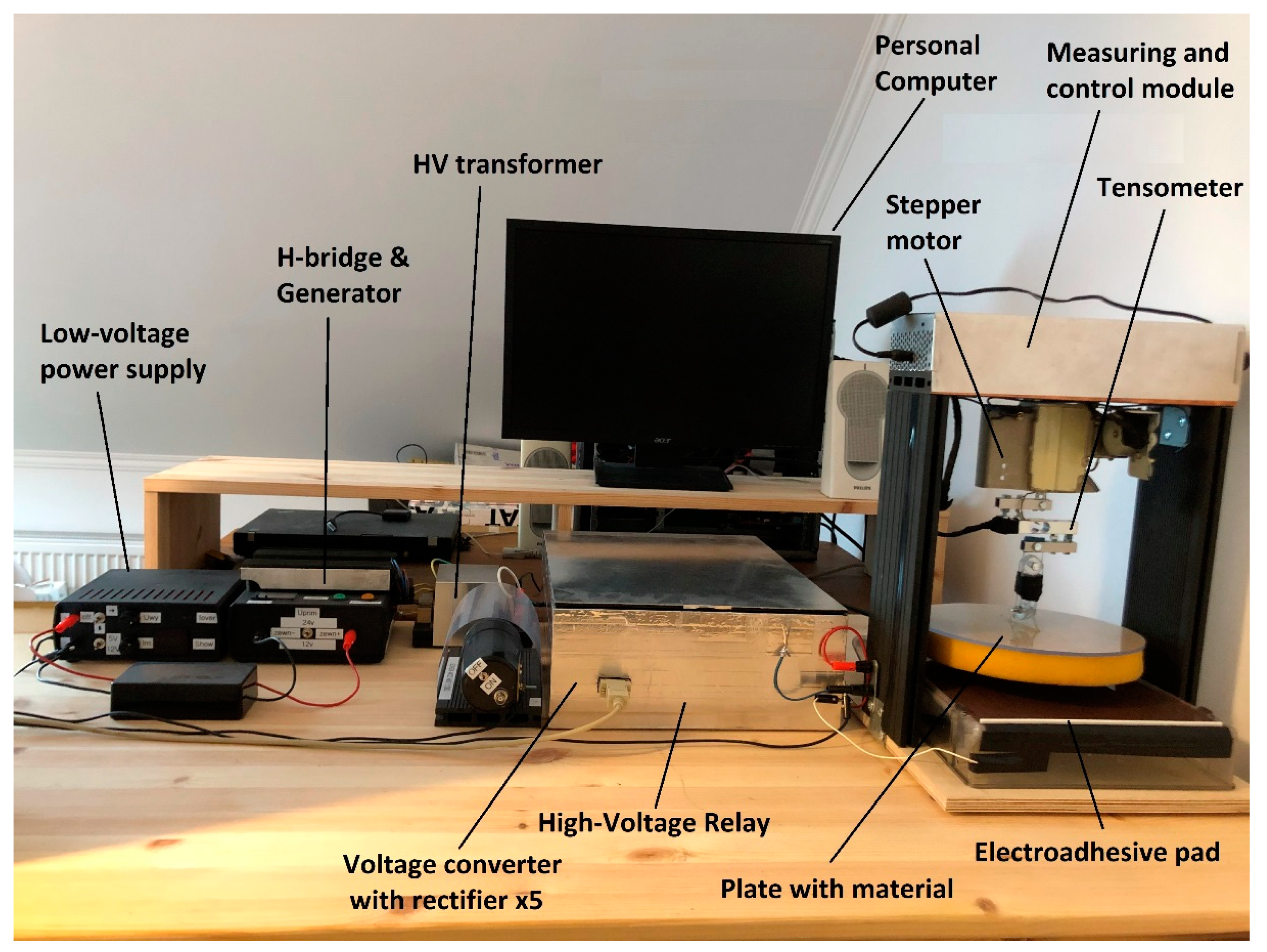
Due to the complex design, the power supply system (Figure 1) and the measurement system (Figure 2) are identified in the system separately. The control system design was initiated on a computer containing the MATLAB suite. The power supply system includes, among others components, a transformer, HV (High Voltage) relay, duplicator and controller. The control was performed from a computer via USB ports. The detailed elements of the system are presented in Figure 1. Low AC (Alternating Current) voltage from the power supply was raised by the transformer and the duplicator to high voltage, and the polarity could be shifted by the HV relay. The polarity settings on the relay have three stages: positive, negative and neutral. A high voltage was transferred from the relay to the electroadhesive pad.
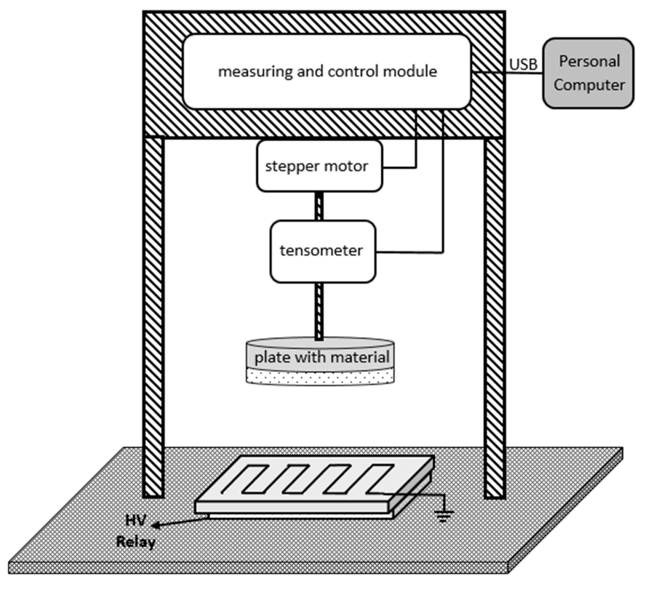
The measuring setup that is presented in Figure 2 comprises a frame on which an arm with a stepper motor control module and a tensiometer is located. At the end of the arm, there is a plate on which the material subjected to testing was placed. The structure was attached to a table made of PVC (Polyvinyl Chloride). An electroadhesive pad was permanently attached to the table to prevent it from rocking throughout the tests. A proprietary construction of an electradhesive pad with dimensions of about 23 cm by 24 cm was designed and built. The electroadhesive pad (Figure 3) was built on a base made of Plexiglas.
On one of the sides, there is copper coating that is coupled to the high voltage supply from the power supply system presented in Figure 1. This side is protected against direct contact, as it is covered with thick insulation. The other side of the pad (in contact with the attracted material) was covered with a copper grid and connected to ground. Such a design ensures the generation of an appropriate electrostatic force and ensures the safety of the pad’s use.
The major electronic components from which the measurement system was constructed are shown in Figure 4. The components of the system are listed below:
  • Voltage converter with rectifier—Villard cascade for positive voltage and separately for negative voltage was built using the Diodec Semiconductor BY16-DIO rectifier diodes and the VISHAY 1500 pF/10 kV high voltage ceramic capacitor.
  • The generator and H-bridge were made by ourselves based on an evaluation module with an MSP-EXP430F5529 microcontroller from Texas Instruments. The module was used as a source of the PWM signal. In addition, an H-bridge was used to strengthen the signal from the generator—built with MOSFETs (Metal-Oxide Semiconductor Field-Effect Transistor): IRFP250 from STMicroelectronics.
  • The measuring and control module was built with the Arduino Uno module with an AVR ATmega328 microcontroller from Microchip and an additional evaluation module with the MSP-EXP430G2553 microcontroller from Texas Instruments. The Arduino module was responsible for data acquisition from the strain gauge: NA27 3kG (30N) SES-03543. The module with the MSP430 controlled the stepper motor through the A4988 Stepper Motor Driver Carrier module from Pololu.
  • Low Voltage Power Supply—A self-built regulated switching power supply controlled from a PC using an evaluation module with an MSP-EXP430FR2355 microcontroller from Texas Instruments, which has analog comparator circuits and AD/DA converters as well as a PWM circuit. These circuits were used to regulate the output voltage of the power supply, in conjunction with an H-bridge module with IRFP250 transistors from STMicroelectronics. The MSP430 module of the power supply additionally controlled the high voltage relay, which was constructed from DAT711215F reed switches from Cynergy3.

3. Measurement Algorithm

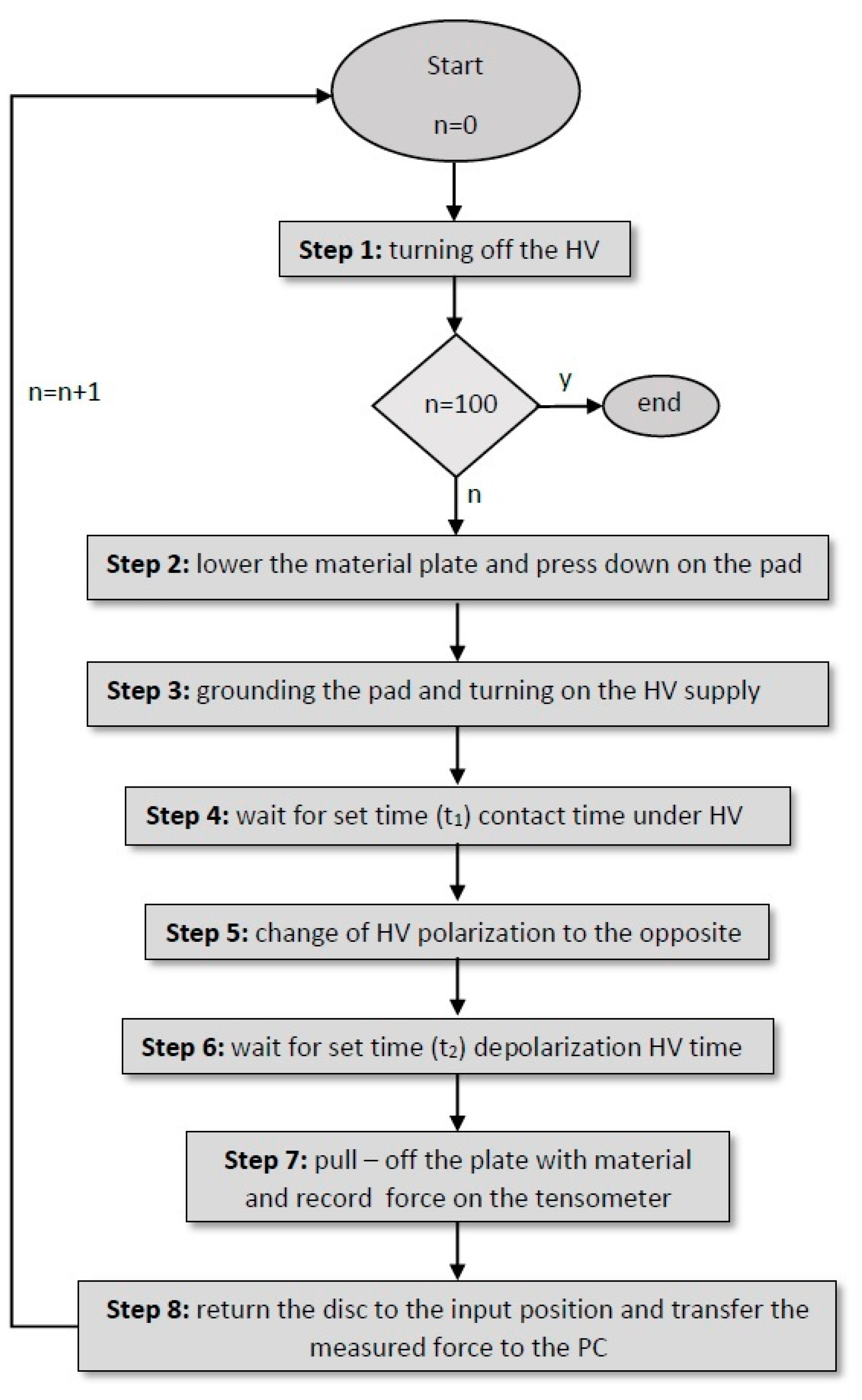
For shifting low voltage to high voltage, the polarity is regulated automatically (by means of high voltage relays). The measuring system is energized and the plate with the material is lowered on the electroadhesive pad. When the material touches the pad, it is additionally pressed for the purposes of gaining better contact between the material and the pad. Then, a given waiting period is set in the program and the voltage polarization is shifted to the opposite.
Again, an interval is set in the program and the plate is lifted along with the material. The electrostatic pad creates an electrostatic field which attracts the material. The resistance force can then be recorded with a tensiometer. During this time, the plate is slowly raised to its starting position. The measured forces are transferred to a computer and the electroadhesive pad is discharged to 0 V. The algorithm followed throughout the measurements is presented in Figure 5.

4. Description of Experiment

In this study, 50 g/m2 paper was applied to test the force with which an electrostatic pad attracts the material. The paper was fixed to a round plate with a diameter of 22 cm.
The dielectric constant of the paper used in this study is 3.5 εr. The arm was controlled by a desktop computer and applied to lower the material plate towards the electroadhesive pad. The measurements were performed by application of a tensiometer with the purpose of measuring the attraction force. The research that was carried out consisted of several separate measurements over time with positive and negative polarization.
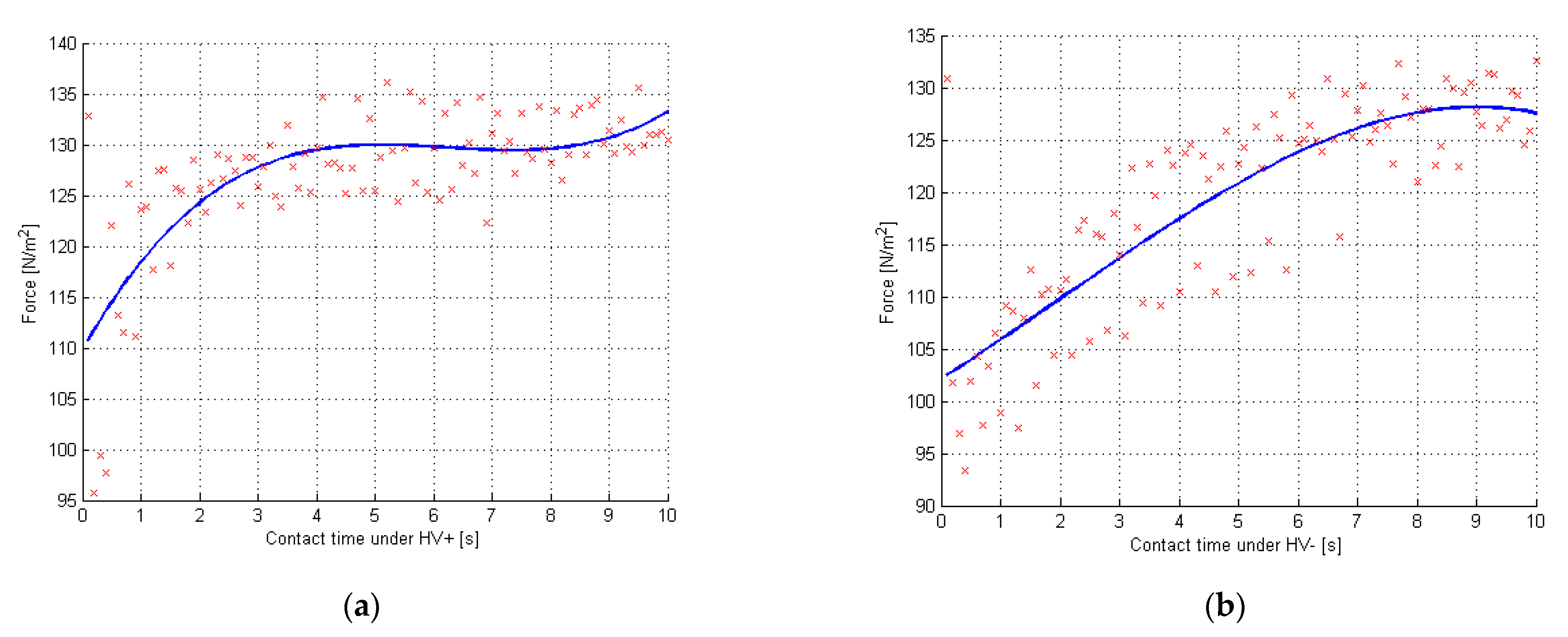
Experiment I (contact time under HV) involved the measurements of the electroadhesive force under a given voltage of 7 kV. After the material plate was lowered, the polarization on the relay was set to HV+ and the preset interval was adopted to achieve the electrification time. Then, the polarity was shifted to HV− and a waiting time of 0.5 s (t1 is repolarization) was applied for the force measurement. After the plate was raised, the tensiometer performed measurements of the maximum force, and these 100 force measurements were expressed in N/m2 (by definition is a unit of pressure — in our study we measured the force with which the electroadhesive pad attracted the object, not what pressure was then generated). The results were recorded in MATLAB and are presented in Figure 6. Then, the experiment I was repeated with the shift of the relay to HV− and subsequently to HV+. The results that were recorded for the positive and negative polarization ranged from 93 N/m2 to 136 N/m2.
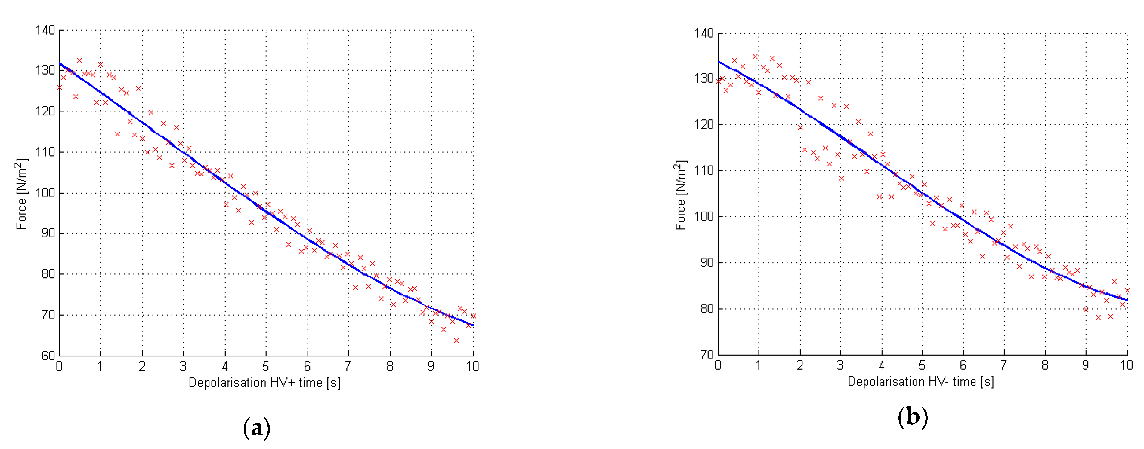
Experiment II (Depolarization HV time) involved the measurement of the electroadhesive force accompanying the depolarization of the pad. The material plate with the paper attached to the plate was lowered. Subsequently, the voltage was set to 7 kV and the relay setting HV+ was applied. After the waiting time for electrification expired (t2 is 10 s polarization), the polarity was shifted to HV−. The following step consisted of waiting for the force measurement and lifting the material plate to read the maximum electroadhesive force and recording the results by the computer. The tensiometer registered 100 measurements and the results are shown in graphs (with an averaged force). The measurement was repeated, first using HV− polarization, followed by HV+. In the case of depolarization, the graphs clearly show a linear decrease in the force. The residual electrostatic field attracts the paper with a force between 70 and 80 N/m2 (Figure 7).
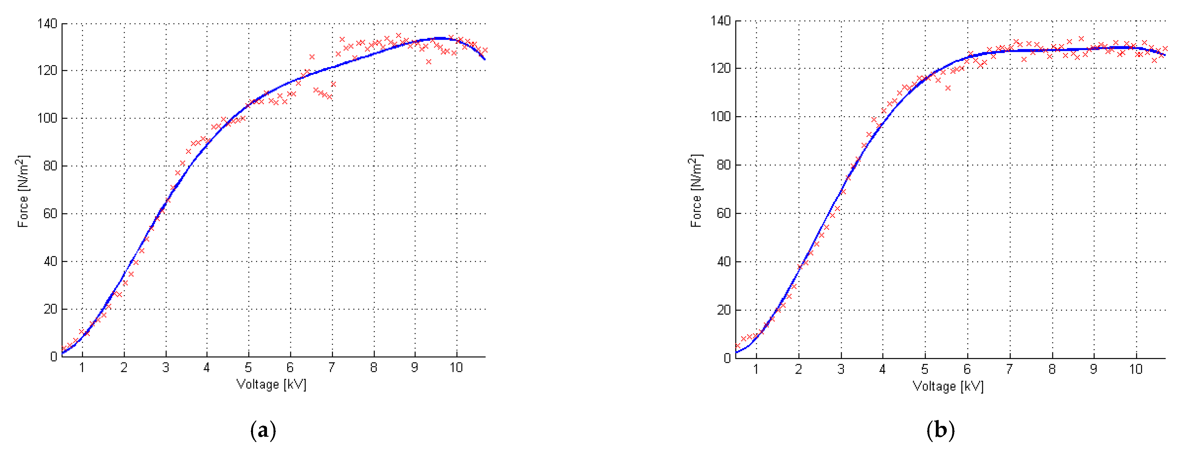
The following stage of the research involved the analysis of the relation of the voltage applied to the electroadhesive pad on the increase in the electroadhesive force. The material plate was lowered and the polarization was set to HV+. The waiting time for electrification was 10 s. After this time, the polarization voltage was shifted to HV−. Figure 8 contains a diagram of the increase in the electroadhesive force with an increase in the given voltage from 0 kV to over 10 kV. The most effective results of the electroadhesive force can be observed in the range from 5 kV to 10 kV.
Throughout all experiments, local voltage drops could be observed, in particular in the conditions when the voltage was high (Figure 8). Additionally, electrical breakdowns in the form of snaps were audible. This is due to the occurrence of partial discharges and fatigue of the material from which the electroadhesive pad is made. The selection of materials from which the pad is made has a significant impact on the distribution of the electroadhesive force. For these tests, the selection of the material provided the possibility of recording the results close to 140 N/m2. All the minimum and maximum results obtained during the experiments are shown in Table 1.

5. Conclusions

This paper includes research related to the effect of various parameters on the generation of the electroadhesive force. The first sections of the paper include an introduction to the concept of electroadhesion in the context of industrial applications due to the action of an attraction force.
The research reported in this paper gives an outline regarding the relation of the electroadhesive force on the voltage that was applied to the tested electroadhesive pad. The electroadhesive pad designed for tests offers greater user safety and better accuracy of measurements. The proposed voltage control algorithm with an adjustable pad and material polarization times offers the possibility of maintaining the required electrostatic attraction force. All measurements were also carried out independently. For this purpose, a measuring system was created and tests were carried out with the use of a tensiometer. Paper was used as the test material, and it took the form of newsprint with a weight of 50 g/m2. The research involved an investigation of the dependence of this force on the polarization and depolarization of the electroadhesive pad. The results are presented in graphs, and they demonstrate that the electroadhesive force rises with increasing high voltage levels, and after a certain voltage level is achieved, the force becomes constant. Additionally, measurements of the dependence of polarization on the force were carried out. The depolarization of the electroadhesive pad led to a significant decrease in the force with which the pad attracted the investigated material. This was due to the decreasing electrostatic force and the decay of high voltage.
The authors of this paper focused on the experimental study of the process of the electroadhesion phenomenon. The mathematical model is a much more complicated and extensive issue than making the measurements. The mathematical model is very important and presents an extremely interesting thought process in learning about the electroadhesion force. The authors foresee the development of a mathematical model in future work.
The scope of future projected work includes the investigation of the dependence of the electroadhesive force on the use of other materials. Research will be carried out with regard to heavier objects to see if they are capable of attracting each other with a similar force to the paper used in this article. The plan also includes investigation of the properties of the electroadhesive force depending on variable environmental conditions, e.g., temperature, pressure and humidity.
The most important part of our future work will be to initiate the modeling of the electroadhesive force in COMSOL or any similar program that can perform simulations. Comparison of simulation results with results obtained on physical electroadhesive pads will certainly generate a new experience, better understanding of the phenomenon of electroadhesion and mark a breakthrough in our work.

Author Contributions

Data curation, J.Z.; Formal analysis, W.K.; Funding acquisition, Ł.N.; Investigation, W.K. and Ł.N.; Methodology, W.K., Ł.N. and J.Z.; Project administration, W.K.; Software, J.Z.; Supervision, Ł.N.; Writing—original draft, W.K.; Writing—review & editing, W.K., Ł.N. and J.Z. All authors have read and agreed to the published version of the manuscript.

Funding

This research received no external funding.

Institutional Review Board Statement

Not applicable.

Informed Consent Statement

Not applicable.

Data Availability Statement

Not applicable.

Conflicts of Interest

The authors declare no conflict of interest.

References

  1. Vankov, A.B.; Huie, P.; Blumenkranz, M.S.; Palanker, D.V. Electroadhesive forceps for tissue manipulation. In Proceedings of the Ophthalmic Technologies XIV Conference, San Jose, CA, USA, 13 July 2004; Volume 5314, pp. 270–275. [Google Scholar]
  2. Berengueres, J.; Urago, M.; Saito, S.; Tadakuma, K.; Meguro, H. Gecko inspired electrostatic chuck. In Proceedings of the 2006 IEEE International Conference on Robotics and Biomimetics, ROBIO 2006, Kunming, China, 17–20 December 2006; pp. 1018–1023. [Google Scholar]
  3. Cao, C.; Sun, X.; Fang, Y.; Qin, Q.; Yu, A.; Feng, X. Theoretical model and design of electroadhesive pad with interdigitated electrodes. Mater. Des. 2016, 89, 485–491. [Google Scholar] [CrossRef] [Green Version]
  4. Saito, S.; Soda, F.; Dhelika, R.; Takahashi, K.; Takarada, W.; Kikutani, T. Compliant electrostatic chuck based on hairy microstructure. Smart Mater. Struct. 2013, 22, 015019. [Google Scholar] [CrossRef]
  5. Dhelika, R.; Sawai, K.; Takahashi, K.; Takarada, W.; Kikutani, T.; Saito, S. Electrostatic chuck consisting of polymeric electrostatic inductive fibers for handling of objects with rough surfaces. Smart Mater. Struct. 2013, 22, 095010. [Google Scholar] [CrossRef] [Green Version]
  6. Téllez, J.P.D.; Krahn, J.; Menon, C. Characterization of Electro-adhesives for Robotic Applications. In Proceedings of the IEEE International Conference on Robotics and Biomimetics, Karon Beach, Thailand, 7–11 December 2011; pp. 1867–1872. [Google Scholar]
  7. Xiang, C.; Guo, J.; Rossiter, J. ContinuumEA: A soft continuum electroadhesive manipulator. In Proceedings of the 2018 IEEE International Conference on Robotics and Biomimetics (ROBIO), Kuala Lumpur, Malaysia, 12–15 December 2018; pp. 2473–2478. [Google Scholar]
  8. Guo, J.; Bamber, T.; Zhao, Y.; Chamberlain, M.; Justham, L.; Jackson, M. Toward adaptive and intelligent electroadhesives for robotic material handling. IEEE Robot. Autom. Lett. 2016, 2, 538–545. [Google Scholar] [CrossRef] [Green Version]
  9. Yamamoto, A.; Nakashima, T.; Higuchi, T. Wall Climbing Mechanisms Using Electrostatic Attraction Generated by Flexible Electrodes. In Proceedings of the International Symposium on Micro-Nano Me2chatronics and Human Science 2007, Nagoya, Japan, 11–14 November 2007; pp. 389–394. [Google Scholar]
  10. Prahlad, H.; Pelrine, R.; Stanford, S.; Marlow, J.; Kornbluh, R. Electroadhesive Robots-Wall Climbing Robots Enabled by A Novel, Robust, and Electrically Controllable Adhesion Technology. In Proceedings of the 2008 IEEE International Conference on Robotics and Automation, Pasadena, CA, USA, 19–23 May 2008; pp. 3028–3033. [Google Scholar]
  11. Pawashe, C.; Floyd, S.; Sitti, M. Multiple magnetic microrobot control using electrostatic anchoring. Appl. Phys. Lett. 2009, 94, 164108. [Google Scholar] [CrossRef] [Green Version]
  12. Graule, M.; Chirarattananon, P.; Fuller, S.; Jafferis, N.; Spenko, M.; Kornbluh, R.; Wood, R. Perching and takeoff of a robotic insect on overhangs using switchable electrostatic adhesion. Science 2014, 352, 978–982. [Google Scholar] [CrossRef] [Green Version]
  13. Wang, H.; Yamamoto, A.; Higuchi, T. Electrostatic-Motor-Driven Electroadhesive Robot. In Proceedings of the 2012 IEEE/RSJ International Conference on Intelligent Robots and Systems, Vilamoura, Portugal, 7–12 October 2012; pp. 914–919. [Google Scholar]
  14. Liu, R.; Chen, R.; Shen, H.; Zhang, R. Wall climbing robot using electrostatic adhesion force generated by flexible interdigital electrodes. Int. J. Adv. Rob. Syst. 2013, 10, 1–9. [Google Scholar] [CrossRef]
  15. Wang, H.; Yamamoto, A. A Thin Electroadhesive Inchworm Climbing Robot Driven by An Electrostatic Film Actuator for Inspection in A Narrow Gap. In Proceedings of the 2013 IEEE International Symposium on Safety, Security and Rescue Robotics, Linkoping, Sweden, 21–26 October 2013; pp. 1–6. [Google Scholar]
  16. Koh, K.H.; Chetty, R.M.K.; Ponnambalam, S.G. Modeling and Simulation of Electrostatic Adhesion for Wall Climbing Robot. In Proceedings of the 2011 IEEE International Conference on Robotics and Biomimetics, Phuket, Thailand, 7–11 December 2011; pp. 2031–2036. [Google Scholar]
  17. Derjaguin, B.V.; Churaev, N.V.; Muller, M.V. Surface Forces; Springer: Boston, MA, USA, 1987. [Google Scholar]
  18. Kendall, K. Molecular Adhesion and Its Applications: The Sticky Universe; Kluwer Academic/Plenum Publishers: New York, NY, USA, 2001. [Google Scholar]
  19. Johnson, K.L.; Kendall, K.; Roberts, A.D. Surface energy and the contact of elastic solids. Proc. R. Soc. Lond. A 1971, 324, 301–313. [Google Scholar]
  20. Derjaguin, B.V.; Muller, V.M.; Toporov, Y.P. Effect of contact deformations on the adhesion of particles. J. Colloid Interface Sci. 1975, 53, 314–326. [Google Scholar] [CrossRef]
  21. Derjaguin, B. Untersuchungen uber die Reibung und Adhasion, IV. Theorie des Anhaftens kleiner Teilchen. Kolloid Z. 1934, 69, 155–164. [Google Scholar] [CrossRef]
  22. Borodich, F.M. The Hertz-type and adhesive contact problems for depth-sensing indentation. Adv. Appl. Mech. 2014, 47, 225–366. [Google Scholar]
  23. Muller, V.M.; Yushchenko, V.; Derjaguin, B.V. On the influence of molecular forces on the deformation of an elastic sphere and its sticking to a rigid plane. J. Colloid Interface Sci. 1980, 77, 91–101. [Google Scholar] [CrossRef]
  24. Maugis, D. Contact, Adhesion and Rupture of Elastic Solids; Springer: Berlin, Germany, 2000. [Google Scholar]
  25. Guo, J.; Tailor, M.; Bamber, T.; Chamberlain, M.; Justham, L.; Jackson, M. Investigation of relationship between interfacial The Sq between the attracted material and the electroadhesive pad will also be investigated. J. Phys. D Appl. Phys. 2016, 49, 035303. [Google Scholar] [CrossRef] [Green Version]
  26. Guo, J.; Bamber, T.; Hovell, T.; Chamberlain, M.; Justham, L.; Jackson, M. Geometric optimisation of electroadhesive actuators based on 3D electrostatic simulation and its experimental verification. IFAC—PapersOnLine 2016, 49, 309–315. [Google Scholar] [CrossRef] [Green Version]
  27. Kalus, W.; Nagi, Ł.; Zygarlicki, J. The pull-off test of different materials using electroadhesive pads. Przegląd Elektrotechniczny 2020, 96, 41–44. [Google Scholar] [CrossRef]
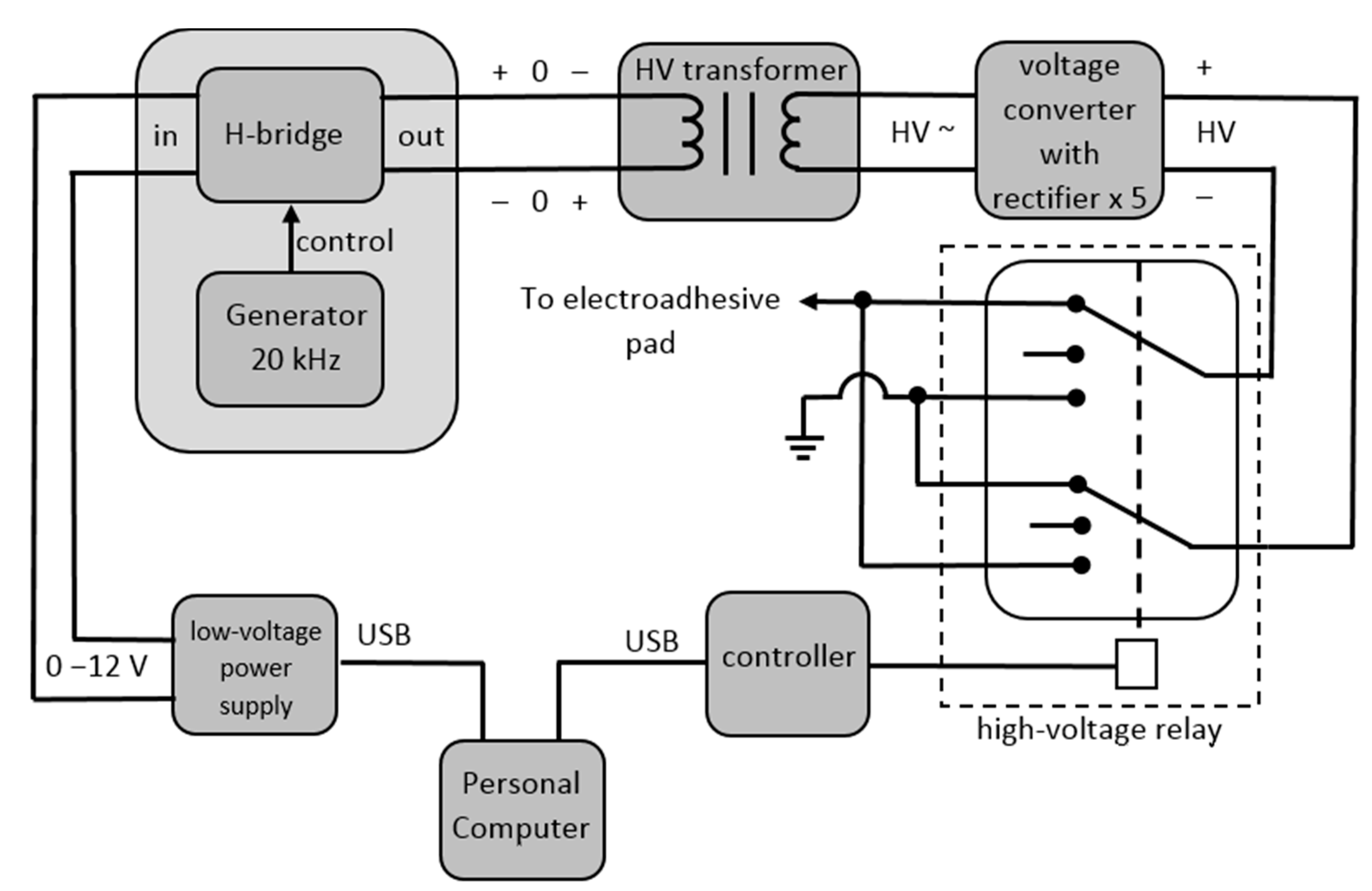
Figure 1. Power supply system.
Energies 14 02517 g001
Figure 2. Diagram of the measuring setup.
Energies 14 02517 g002
Figure 3. Design of the electroadhesive pad.
Energies 14 02517 g003
Figure 4. The actual measurement system.
Energies 14 02517 g004
Figure 5. Block diagram of the algorithm followed throughout the measurements using the electroadhesive force.
Energies 14 02517 g005
Figure 6. Charts representing the dependence of the electroadhesive force on the given polarization (a) HV+ and (b) HV−.
Energies 14 02517 g006
Figure 7. Dependence of the attraction force during depolarization of the electroadhesive pad under a given polarization (a) HV+ and (b) HV−.
Energies 14 02517 g007
Figure 8. Dependence of the force on the voltage increase. Measurements were performed for (a)positive polarization, (b) negative polarization.
Energies 14 02517 g008
Table 1. Lowest and highest results of the measured electroadhesive force.
NamePolarizationMin (N/m2)Max (N/m2)
Experiment I
Contact time under HV
HV+94136
HV−94134
Experiment II
Depolarization HV time
HV+78135
HV−65132
Experiment III
Voltage
HV+3135
HV−4132
Publisher’s Note: MDPI stays neutral with regard to jurisdictional claims in published maps and institutional affiliations.