1. Introduction
This paper presents the preliminary studies of the development process of an LTCC-based microfluidic-microwave device. The growing interest in microfluidic devices is driven by several factors. These include the low volume of liquids and reagents, small dimensions and the possibility of combining the microfluidic components with a wide range of systems. Most of these systems are called lab-on-chip (LOC) microsystems or micro-total-analysis-systems (µTAS) [
1,
2,
3,
4,
5]. The application areas include micromixers, microreactors and more [
6,
7,
8,
9,
10,
11,
12,
13,
14]. Such systems can be manufactured using various technologies, which are strongly connected with the desired application. Many sensing applications are using microfluidic components. The method of detection involved can vary. The common solutions are based on optical [
15,
16,
17], electrochemical [
18], acoustical [
19] and electromagnetic [
20,
21,
22,
23,
24] components. Moreover, the microreactors designed for continuous, as well as for digital microfluidics can be found in the literature [
25,
26,
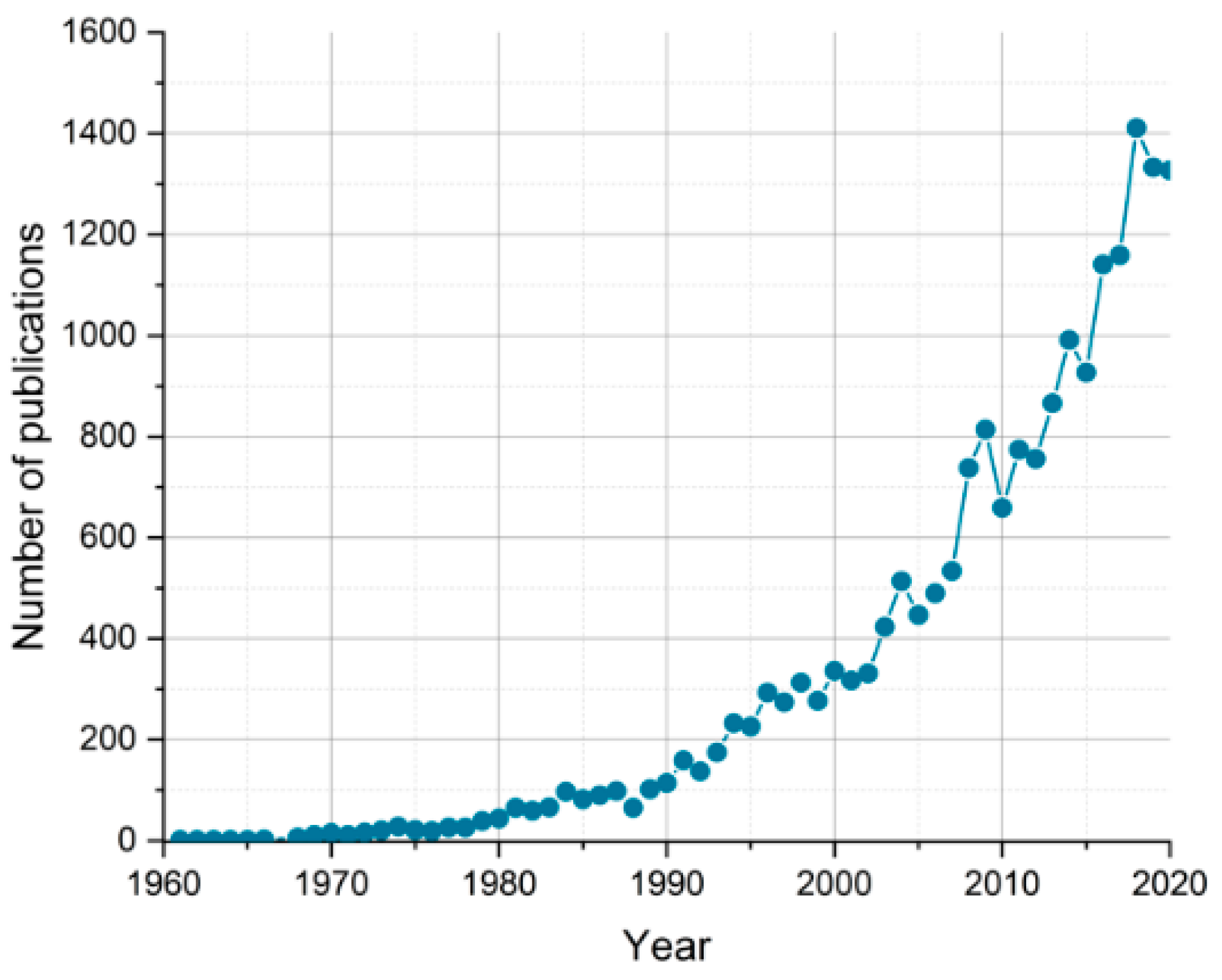
27]. The last area typically includes circuits that are characteristic of the microwave technique. The trend of a growing number of publications describing microwave sensing devices is shown in
Figure 1.
Low temperature co-fired ceramics (LTCC) seems to be a suitable substrate for the systems that incorporate microwave and microfluidic components. Firstly, it is possible to manufacture various conductive paths which can act as a microwave circuit. Moreover, these circuits can be manufactured directly on top of the structure, as well as inside the substrate. Therefore, it is possible to create both the microstrip- and stripline-based microwave circuits [
29,
30]. Besides, many examples of the three-dimensional structures placed inside the LTCC structure can be found in the literature, i.e., microchannels, microchambers, micromixers, etc. [
31,
32,
33]. In opposite to various polymer-based microfluidic-microwave structures, due to the multilayer character of the mentioned technology, the LTCC allows the fabrication of monolithic microfluidic-microwave devices [
34]. Furthermore—the unit cost of manufacturing the LTCC device is much lower in comparison to the technology based on the glass/silicon substrates. Recently, some applications of microfluidic-microwave devices have appeared, such as fluidic sensors, plasma density measurement sensor or microwave spectroscopy sensors [
34,
35,
36].
The most common microfluidic-microwave devices are based on solutions with the use of microstrip or coplanar waveguides (CPW) lines. Among other things, this is dictated by the type of substrate. Based on the literature reports, it may be concluded that the stripline-based circuits integrated with the microfluidic components are rarely present. Nevertheless, the use of such systems would extend the area of microfluidics, especially in the presence of harsh chemical reagents. Moreover, the risk of the influence of the background noises can be reduced with the use of a stripline instead of the microstrip line. The advantages of using integrated striplines with microfluidic components are as follows:
The LTCC is suitable for fabrication of the monolithic microfluidic-microwave devices—both from the perspective of fabricating the conductive paths, as well as the three-dimensional structures inside the structure.
The LTCC is stable in harsh environmental conditions, while conductive paths are much more vulnerable. The possibility of burying them inside the structure significantly improves the sensor lifetime in these conditions.
However, during the preceding design and fabrication of such structures, numerous challenges have been encountered, which are mainly related to the process of delivering the microwave signal directly to the stripline. The fact of being placed inside the structure, with the presence of ground planes over the whole structure, strongly limits how the microwave connectors can be fed. For this reason, the main novelty applied in the proposed device are connectors soldered directly to the stripline.
2. Materials and Methods
The appearance of the microchannel inside the structure strongly affected the designing process of microwave modules. In conventional applications, the microwave circuits are fabricated using a homogeneous substrate. Subsequently, the characteristic geometry (width and length) is developed using analytical methods. However, the microchannels presence requires using more sophisticated calculation methods, such as the finite element method (FEM). This method is based on the calculation of the approximate solutions of partial differential equations. The geometry of the proposed module has been developed using COMSOL Multiphysics (Radio Frequency Module), which is based on the aforementioned computational method. The selection of numerical modelling was driven by the appearance of the microfluidic channel near the stripline circuit. The simulations were carried out in the frequency domain in the range of 0.1–10 GHz with 100 MHz steps. Both the stripline as well as the ground planes were modelled as perfect conductors. The excitations were performed using the coaxial lumped port mode with the characteristic impedance of 50 Ω. Such excitations were chosen due to the distance between the stripline and the ground planes being shorter than the wavelength of the signal. The simulations were carried out in several steps. First, the device with a stripline without a microchannel was modelled. Subsequently, the microchannels with different parameters were added and modelled. Then the connectors were integrated into the model. The deionized (DI) water has been selected as the test liquid. The microchannel was designed to be in close distance (144 µm—one layer of the LTCC) above and below the stripline. In the described module, the stripline was placed in the middle of the substrate and the microchannel was divided into two parts that were directly above and below the stripline with a height equal to 213 µm. The thickness of the whole module and the height of the microchannel were imposed by the layered nature of the LTCC modules. The geometry model of the designed structure is shown in
Figure 2.
The width and length of the modelled stripline were 0.9 and 50 mm, respectively. The obtained width, length and thickness of the LTCC substrate were 10, 50 and 1.57 mm. The length of the microchannel placed directly above and below the stripline was 45 mm. After modelling, the next stage was fabrication of the actual device. DuPont 951 ceramic foil (DuPont (UK) Electronic Materials Ltd., London Rd, Stevenage, United Kingdom) was chosen as the substrate material, with a layer thickness of approximately 144 µm (layers 4 and 5) and 213 µm (layers 1–3 and 6–8) after co-firing. The geometry of the individual layer is shown in
Figure 3.
The stripline was deposited on the fourth layer (l4 in
Figure 4) using a screen printing method with the ESL903A silver conductive paste (sheet resistance ≤ 2 mΩ/□) with use of the Aurel VS 1520A screen printer (Aurel S.p. A, Modilgiana, Italy). The microchannels were fabricated using the LPKF ProtoLaser U laser system (λ = 355 nm, LPKF Laser&Ελεχτρονιχσ, Garbsen, Germany). Thereafter, all layers were stacked together and laminated in the isostatic press with reduced pressure (compared to the 20 MPa recommended by the manufacturer), for 10 min at a temperature of 70 °C. The laminated layers were then formed into the desired shape with the aforementioned laser system. Afterwards, the modules were co-fired in the Nabertherm 03/16 chamber furnace (Nabertherm GmbH, Lilienthal, Germany) with the maximum (peak) temperature of 880 °C. Subsequently, the ground planes were deposited with the mentioned screen printing method using the ESL903D conductive paste with the sheet resistance ≤ 2 mΩ/□. The metallization was post-fired using the BTU QA 41-6-54 belt furnace with the maximum temperature of 850 °C. The final step of the fabrication process was the soldering of the SMA connectors and assembling the steel needles, which act as the inlet and the outlet of the microchannel. After fabrication, the module was examined for the possible presence of undesired electrical connections between the ground and the stripline with the use of the multimeter and the X-ray imaging method. Pictures of the manufactured module along with the X-ray images are shown in
Figure 4 and
Figure 5.
The X-ray images indicate that the stripline of the LTCC module was placed directly in the middle of the substrate (
Figure 5a,b) and no damages were observed. The darker areas are the microchannel that surrounds the stripline (
Figure 5a) and the lighter parts are conductive materials, such as the previously mentioned stripline (
Figure 5b). The measurements of the scattering parameters were carried out after verifying the correct geometry of the module.
3. Results
The stripline-based microfluidic-microwave module was evaluated using an N5230A vector network analyzer (VNA, Agilent, Santa Clara, California, USA). The measurements were preceded by short-open-load-through (SOLT) calibration and the investigated frequency range was from 300 MHz to 12 GHz. As test liquids, deionized water, the ethanol-water solution (with the volume concentration of ethanol equal to 50%) and the ethanol were selected. Such an approach was chosen to check the possibility of extending further research in the area of sensors.
The results of the conducted experiment are presented in
Figure 6a,b with solid lines for the first module and dashed lines for the second one. The liquid used during the modelling of the designed module was deionized water with a relative permittivity of 81. This is the reason why the reflectance of the microwave circuit is the lowest for the mentioned liquid. For each of the measured LTCC modules, the transmittance of the DI water is higher than −3 dB in different frequency ranges. The cut-off frequency of the first module was around 9 GHz (
Figure 6), while the second one was around 8 GHz. The phenomena associated with such behaviour of the LTCC microwave planar circuits were described by Szostak et al. [
37].
The observed increase of the losses (
Figure 6b) for higher frequencies are typical for the water solutions. Moreover, the deformations of the stripline could have additionally strongly increased losses. Such deformations are present due to the nature of the manufacturing process of the LTCC modules and the use of screen-printing method. Therefore, the described area of the LTCC devices requires further research. However, as it can be seen, the tested structures are characterized by only a slight matching difference, due to the similar scattering characteristics. The possible reasons behind the variation of the scattering parameters of each module are discussed in the next section.
4. Discussion
The obtained results highlighted the mismatch between modules, which can be observed mostly in transmittance and reflectance at frequencies higher than 8 GHz for each module. Therefore, the authors decided to perform the cross-section across the module (in 10 mm increments along the microchannel) in order to find possible inaccuracies in the structure geometry. Pictures of the cross-sections are shown in
Figure 7a–f.
The cross-sections demonstrate that there were several issues. Firstly, a slight displacement between the microchannel and the stripline can be observed (
Figure 7c,d,f). Secondly, the delamination of the ceramic layers (
Figure 7c,e,f) can be seen—small darker areas below the microchannel. Moreover, another small delamination is present in
Figure 7a,b—on the left side of the stripline. Furthermore, the stripline is partially deformed (
Figure 7d). The aforementioned facts probably strongly affected the electrical parameters of the substrate, which could influence the circuit behaviour by filtering the signal at higher frequencies. Probably, the main cause of the delamination was the lower lamination pressure, which had been chosen instead of the recommended one in order to minimize the risk of deformation of the microchannel geometry. The obtained results and the cross-sections of the modules indicate that there is a requirement for further research to achieve the optimal conditions throughout the LTCC fabrication process.
Nevertheless, it was observed that the scattering parameters of the tested module were not prone to changes in the arrangement of cables or the position of the module itself. According to the measurements of modules based on a microstrip line (and with combined stripline and microstrip line parts), the improvement of the repeatability and stability of measurements is evident.
The comparison between the results of various liquids indicates the potential of using the presented module in the sensing area of microfluidic systems in the future. Visible changes of S11 and S21 parameters in a wide range of frequency with the fluid change in the microchannel can be observed.
5. Conclusions
The LTCC stripline-based microfluidic module was developed, manufactured and measured. In contrary to the solutions found in the literature, a waveguide in the form of a stripline (buried inside a ceramic structure) with the presence of a microchannel was chosen. The fabrication process was preceded by the numerical simulations utilising the COMSOL Multiphysics software. The modelled and tested frequency range included the most commonly used frequencies in the telecommunication industry—2.4 GHz and 5.1 GHz. Therefore, the components for the further development of the proposed solution are available and cost-effective.
The module was examined in the presence of several liquids—deionized water, the ethanol-water solution with the ethanol volume concentration of 50% and the pure anhydrous ethanol. The changes of the scattering parameters were observed for every single liquid. Thus, it shows the potential of further project development towards dielectric sensing. However, the proposed module requires additional investigations due to the appearance of geometry deviations.
The selection of the LTCC is determined by the characteristics of the aforementioned material. Among them, the appropriate dielectric properties, high-temperature stability, possibility of simple micromechanical processing can be mentioned. Therefore, the LTCC technology appears as an attractive alternative to other technologies that are chosen to fabricate the microwave-microfluidic structures.
Author Contributions
Conceptualization, L.J. and K.S.; methodology, L.J., K.S. and M.C.; validation, K.M. and P.S.; investigation, L.J., K.S. and M.C.; resources, L.J.; data curation, L.J., K.S. and M.C.; writing—original draft preparation, L.J.; writing—review and editing, K.S., M.C., K.M. and P.S., visualization, L.J. and M.C.; supervision, K.M. and P.S.; project administration, K.M.; funding acquisition, K.M. All authors have read and agreed to the published version of the manuscript.
Funding
This research was funded by Wrocław University of Science and Technology (statutory activity).
Institutional Review Board Statement
Not applicable.
Informed Consent Statement
Not applicable.
Data Availability Statement
Not applicable.
Conflicts of Interest
The authors declare no conflict of interest.
References
- Cui, Y.; Li, J.; Cao, W.; Wang, P. Highly sensitive RF detection and analysis of DNA solutions. In Proceedings of the 2014 IEEE MTT-S International Microwave Symposium (IMS2014), Tampa, FL, USA, 1–6 October 2014; pp. 6–9. [Google Scholar] [CrossRef]
- Artis, F.; Dubuc, D.; Fournié, J.J.; Poupot, M.; Grenier, K. Microwave dielectric bio-sensing for precise and repetitive living cells suspension analysis. In Proceedings of the 2013 European Microwave Conference, Nuremberg, Germany, 6–10 October 2013; IEEE: New York, NY, USA, 2013; pp. 468–470. [Google Scholar] [CrossRef]
- Lee, H.J.; Yook, J.G. Recent research trends of radio-frequency biosensors for biomolecular detection. Biosens. Bioelectron. 2014, 61, 448–459. [Google Scholar] [CrossRef]
- Olapinski, M.; Manus, S.; George, M.; Brüggemann, A.; Fertig, N.; Simmel, F.C. Detection of lipid bilayer and peptide pore formation at gigahertz frequencies. Appl. Phys. Lett. 2006, 88, 013902. [Google Scholar] [CrossRef]
- Dutse, S.W.; Yusof, N.A. Microfluidics-based lab-on-chip systems in DNA-based biosensing: An overview. Sensors 2011, 11, 5754–5768. [Google Scholar] [CrossRef]
- Abdolrazzaghi, M.; Daneshmand, M.; Iyer, A.K. Strongly enhanced sensitivity in planar microwave sensors based on metamaterial coupling. IEEE Trans. Microw. Theory Tech. 2018, 66, 1843–1855. [Google Scholar] [CrossRef]
- Abduljabar, A.A.; Rowe, D.J.; Porch, A.; Barrow, D.A. Novel microwave microfluidic sensor using a microstrip split-ring resonator. IEEE Trans. Microw. Theory Tech. 2014, 62, 679–688. [Google Scholar] [CrossRef]
- Ebrahimi, A.; Withayachumnankul, W.; Al-Sarawi, S.; Abbott, D. High-sensitivity metamaterial-inspired sensor for microfluidic dielectric characterization. IEEE Sens. J. 2014, 14, 1345–1351. [Google Scholar] [CrossRef]
- Velez, P.; Su, L.; Grenier, K.; Mata-Contreras, J.; Dubuc, D.; Martin, F. Microwave microfluidic sensor based on a microstrip splitter/combiner configuration and split ring resonators (SRRs) for dielectric characterization of liquids. IEEE Sens. J. 2017, 17, 6589–6598. [Google Scholar] [CrossRef]
- Salim, A.; Kim, S.-H.H.; Park, J.Y.; Lim, S. Microfluidic biosensor based on microwave substrate-integrated waveguide cavity resonator. J. Sens. 2018, 2018, 1–13. [Google Scholar] [CrossRef]
- Markovic, T.; Bao, J.; Ocket, I.; Kil, D.; Brancato, L.; Puers, R.; Nauwelaers, B. Uniplanar microwave heater for digital microfluidics. In Proceedings of the 1st IEEE MTT-S International Microwave Bio Conference (IMBioC 2017), Gothenburg, Sweden, 15–17 May 2017; pp. 1–4. [Google Scholar] [CrossRef]
- Bao, X.; Ocket, I.; Crupi, G.; Schreurs, D.; Bao, J.; Kil, D.; Puers, B.; Nauwelaers, B. A planar one-port microwave microfluidic sensor for microliter liquids characterization. IEEE J. Electromagn. RF Microw. Med. Biol. 2018, 7249, 10–17. [Google Scholar] [CrossRef]
- Yesiloz, G.; Boybay, M.S.; Ren, C.L. Effective thermo-capillary mixing in droplet microfluidics integrated with a microwave heater. Anal. Chem. 2017, 89, 1978–1984. [Google Scholar] [CrossRef]
- Marchiarullo, D.J.; Sklavounos, A.H.; Oh, K.; Poe, B.L.; Barker, N.S.; Landers, J.P. Low-power microwave-mediated heating for microchip-based PCR. Lab Chip 2013, 13, 3417–3425. [Google Scholar] [CrossRef] [PubMed]
- Aristilde, S.; Soares, M.C.P.; Cabral, T.D.; Rodrigues, G.; Fujiwara, E.; Fruett, F.; Cordeiro, C.M.B. Measurement of multiphase flow by tilted optical fiber bragg grating sensor. IEEE Sens. J. 2021, 21, 1534–1539. [Google Scholar] [CrossRef]
- Jderu, A.; Soto, M.A.; Enachescu, M. Liquid flow meter by fiber-optic sensing of heat propagation. Sensors 2021, 21, 355. [Google Scholar] [CrossRef] [PubMed]
- Steinegger, A.; Wolfbeis, O.S.; Borisov, S.M. Optical sensing and imaging of pH Values: Spectroscopies, materials, and applications. Chem. Rev. 2020, 120, 12357–12489. [Google Scholar] [CrossRef] [PubMed]
- Spychalska, K.; Zaja, D.; Cabaj, J. Electrochemical biosensor for detection of 17β-estradiol using semi-conducting polymer and horseradish peroxidase. RSC Adv. 2020, 10, 9079–9087. [Google Scholar] [CrossRef]
- Guliy, O.; Zaitsev, B.; Teplykh, A.; Balashov, S.; Fomin, A.; Staroverov, S.; Borodina, I. Acoustical Slot Mode Sensor for the Rapid Coronaviruses Detection. Sensors 2021, 21, 1822. [Google Scholar] [CrossRef] [PubMed]
- Zhang, L.Y.; Bounaix Morand Du Puch, C.; Dalmay, C.; Lacroix, A.; Landoulsi, A.; Leroy, J.; Mélin, C.; Lalloué, F.; Battu, S.; Lautrette, C.; et al. Discrimination of colorectal cancer cell lines using microwave biosensors. Sens. Actuators A Phys. 2014, 216, 405–416. [Google Scholar] [CrossRef]
- Liu, T.M.; Chen, H.P.; Wang, L.T.; Wang, J.R.; Luo, T.N.; Chen, Y.J.; Liu, S.I.; Sun, C.K. Microwave resonant absorption of viruses through dipolar coupling with confined acoustic vibrations. Appl. Phys. Lett. 2009, 94, 92–95. [Google Scholar] [CrossRef]
- Liang, Y.; Ma, M.; Zhang, F.; Liu, F.; Liu, Z.; Wang, D.; Li, Y. An LC wireless microfluidic sensor based on low temperature co-fired ceramic (LTCC) technology. Sensors 2019, 19, 1189. [Google Scholar] [CrossRef]
- Hamzah, H.; Lees, J.; Porch, A. Split ring resonator with optimised sensitivity for microfluidic sensing. Sens. Actuators A Phys. 2018, 276, 1–10. [Google Scholar] [CrossRef]
- Abduljabar, A.A.; Choi, H.; Barrow, D.A.; Porch, A. Adaptive Coupling of Resonators for Efficient Microwave Heating of Microfluidic Systems. IEEE Trans. Microw. Theory Tech. 2015, 63, 3681–3690. [Google Scholar] [CrossRef]
- Markovic, T.; Ocket, I.; Baric, A.; Nauwelaers, B. Design and comparison of resonant and non-resonant single-layer microwave heaters for continuous flow microfluidics in silicon-glass technology. Energies 2020, 13, 2635. [Google Scholar] [CrossRef]
- Abduljabar, A.A.; Choi, H.; Porch, A. Novel variable coupling technique for microwave liquid heating and sensing. In Proceedings of the 18th Mediterranean Microwave Symposium (MMS), Istanbul, Turkey, 31 October–2 November 2018; IEEE: New York, NY, USA, 2019; pp. 334–336. [Google Scholar] [CrossRef]
- Markovic, T.; Liu, S.; Ocket, I.; Nauwelaers, B.K.J.C. A 20 GHz microwave heater for digital microfluidic. Int. J. Microw. Wirel. Technol. 2017, 9, 1591–1596. [Google Scholar] [CrossRef]
- Scopus Database. Available online: https://www.scopus.com/results/results.uri?numberOfFields=0&src=s&clickedLink=&edit=&editSaveSearch=&origin=searchbasic&authorTab=&affiliationTab=&advancedTab=&scint=1&menu=search&tablin=&searchterm1=microwave+microfluidic+sensor&field1=TITLE_ABS_KEY&date (accessed on 15 March 2021).
- Sukaimi, N.H.M.; Ali, M.T.; Subahir, S.; Jumaat, H.; Faudzi, N.M. A multilayer fractal patch antenna using LTCC technology. In Proceedings of the 2013 IEEE International RF and Microwave Conference (RFM), Penang, Malaysia, 9–11 December 2013; pp. 356–361. [Google Scholar]
- Jost, M.; Strunck, S.; Heunisch, A.; Wiens, A.; Prasetiadi, A.E.; Weickhmann, C.; Schulz, B.; Quibeldey, M. Continuously tuneable liquid crystal based stripline phase shifter realised in LTCC technology. In Proceedings of the 2015 European Microwave Conference (EuMC), Paris, France, 7–10 September 2015; pp. 409–412. [Google Scholar]
- Malecha, K.; Remiszewska, E.; Pijanowska, D.G. Technology and application of the LTCC-based microfluidic module for urea determination. Microelectron. Int. 2015, 32, 126–132. [Google Scholar] [CrossRef]
- Malecha, K. The utilization of LTCC-PDMS bonding technology for microfluidic system applications-a simple fluorescent sensor. Microelectron. Int. 2016, 33, 141–148. [Google Scholar] [CrossRef]
- Luo, J.; Eitel, R. An integrated low temperature co-fired ceramic-based clark-type oxygen sensor. IEEE Sens. J. 2017, 17, 1590–1595. [Google Scholar] [CrossRef]
- Malecha, K.; Jasińska, L.; Grytsko, A.; Drzozga, K.; Slobodzian, P.; Cabaj, J. Monolithic microwave-microfluidic sensors made with low temperature co-fired ceramic (LTCC) technology. Sensors 2019, 19, 577. [Google Scholar] [CrossRef] [PubMed]
- Zhao, Z.; Zhang, H.; Zeng, L.; Tian, X. A Plasma Density Measurement Sensor Based on a LTCC Antenna. In Proceedings of the 2019 Photonics & Electromagnetics Research Symposium—Fall (PIERS—Fall), Xiamen, China, 17–20 December 2019; pp. 17–20. [Google Scholar]
- Hosseini, N.; Baghelani, M.; Daneshmand, M. Discrete microwave spectroscopy using planar resonator. In Proceedings of the 2019 IEEE Canadian Conference of Electrical and Computer Engineering (CCECE), Edomnton, AB, Canada, 5–8 May 2019; IEEE: New York, NY, USA, 2019. [Google Scholar]
- Szostak, K.; Kiliszkiewicz, M.; Jasinska, L.; Slobodzian, P.; Korbutowicz, R.; Malecha, K. Inkjet printed vs screen printed microstrip line on LTCC substrates. In Proceedings of the 2019 Conference on Microwave Techniques, Pardubice, Czech Republic, 16–18 April 2019. [Google Scholar]
| Publisher’s Note: MDPI stays neutral with regard to jurisdictional claims in published maps and institutional affiliations. |
© 2021 by the authors. Licensee MDPI, Basel, Switzerland. This article is an open access article distributed under the terms and conditions of the Creative Commons Attribution (CC BY) license (https://creativecommons.org/licenses/by/4.0/).


