Article

Effect of Pole Shoe Design on Inclination Angle of Different Magnetic Fields in Permanent Magnet Machines

Department of Electrical Engineering, Division of Electricity, Uppsala University, 752 37 Uppsala, Sweden
*
Author to whom correspondence should be addressed.
Energies 2021, 14(9), 2437; https://doi.org/10.3390/en14092437
Submission received: 19 March 2021 / Revised: 8 April 2021 / Accepted: 19 April 2021 / Published: 24 April 2021
(This article belongs to the Special Issue Permanent Magnet Machines for Wave Energy Converters)

Abstract

:
Electromagnetic modelling of electrical machines through finite element analysis is an important design tool for detailed studies of high resolution. Through the usage of finite element analysis, one can study the electromagnetic fields for information that is often difficult to acquire in an experimental test bench. The requirement for accurate result is that the magnetic circuit is modelled in a correct way, which may be more difficult to maintain for rare earth free permanent magnets with an operating range that is more likely to be close to non-linear regions for the relation between magnetic flux density and magnetic field strength. In this paper, the inclination angles of the magnetic flux density, magnetic field strength and magnetization are studied and means to reduce the inclination angles are investigated. Both rotating and linear machines are investigated in this paper, with different current densities induced in the stator windings. By proper design of the pole shoes, one can reduce the inclination angles of the fields in the permanent magnet. By controlling the inclination angles, one can both enhance the performance of the magnetic circuit and increase the accuracy of simpler models for permanent magnet modelling.

1. Introduction

Electromagnetic design of electrical machines has been an area of great interest for a long time. The arrival of computer-aided tools has allowed for studies that depict the behaviour of machines of great resolution with more ease. The accuracy of these tools is progressively increasing. One of the branches of electromagnetic design is the usage of permanent magnets (PM)s for magnetic induction in the machine. With the discovery and development of rare earth magnets, the application of permanent magnets in machines has expanded and established PM usage as a competitive counterpart to electromagnets or induction machines. A benefit of rare earth magnets, besides their great energy product, high remanent flux density and coercive field, is that they appear linear in the second quadrant of the magnetic flux density-to-magnetic field strength (BH)-curve under most conditions. This allows for simpler models in computer-aided finite-element softwares with a maintained high accuracy. Due to the nature of rare earth magnets and the relatively scarce supply of these magnets, there has been great interest in research utilizing other, more abundant, materials.
Two of the alternatives are ferrites and Alnico magnets. A great drawback of these replacements are that they lack key properties that make rare earth magnets so great, meaning that they lack the combination of a high-maximum-energy product, remanent flux density and coercivity. Furthermore, for Alnico magnets, the major loop is non-linear in the 2nd quadrant. The result of this is that further investigation and regard for irreversible demagnetization is a must. Beyond that, most models for irreversible demagnetization and the BH-curves supplied by manufacturers are one-dimensional. The coercivity and ultimately irreversible demagnetization may behave differently when there are considerable inclination angles between magnetization, magnetic field strength and magnetic flux density. In [1], it was pointed out that the inclined behaviour of the irreversible demagnetization for rare earth magnets should be considered at inclined fields as low as 20 , which is not uncommon for permanent magnet bulk materials in electrical machines.
Most rare-earth free magnets have a remanent magnetic flux density that is lower, and in order to reach similar flux density in the air gap, flux-concentrating topologies are necessary. The usage of such topologies will cause a rapid change in direction of the magnetic flux density close to the borders of the PMs. In other words, the flux density outside the PMs will act perpendicular to the magnetization direction inside the magnets, which will subsequently impact the direction of the magnetic field strength close to the boundary. This means that the direction of the magnetic field strength within the permanent magnet is greatly influenced by the magnetic circuit outside the permanent magnets (e.g., the soft magnetic poles).
Most design studies for the magnetic circuit of the pole shoes investigate the behaviour of the magnetic flux density in the pole shoes and the harmonics in the air gap. A selection of those required for a sinusoidal air gap flux density [2]: inverse sine, concentrated, tapered and elliptic [3]; Total harmonic distortion behaviour for different surface-mounted outer polse [4]; Sinusoidal air gap flux density through varied air gap length in a reluctance model [5]; reduced electromagnetic losses by modifying the offset of the circular origin that forms the pole face [6]; cogging and torque optimization by changing the inclination of the V-shaped PMs and the bridge dimension that controls the leakage flux [7].
Few studies concern the implications the pole shoe has on the magnetic flux density within the relatively weak rare-earth free magnets, and even fewer include the inclination angle of the magnetic field strength, magnetic flux density and the magnetization. In [2], the irreversible demagnetization is determined through a threshold flux density, which is most likely the absolute value, although it is not clearly stated. In [8], the parallel component of the magnetic flux density was used to determine the risk of irreversible demagnetization. In [9], the remanent flux density was reduced to a new, lower value in a study for a two-piece linear BH-curve. In [1], inclination angles for the irreversible demagnetization were accounted for by introducing an angular dependency to the intrinsic coercivity in a BH-curve, where the knee was expressed as an exponential function. In [10], a transformer core was used in a testbench to investigate the irreversible demagnetization in the magnetization direction. Another example of the inclined dependency is in [11], where experimental results for prisms and rectangular PM samples are compared to finite-element simulations using a misalignment distribution function for the PM segments. Allowing for inclination angle in the context of electrical machine applications will make the simulations much more complex.
In this paper, the spatial distribution of the inclination angles of the magnetic flux density, magnetic field strength and magnetization is investigated for different pole shoe designs. The key questions of the paper are how the inclination angles within the magnets are influenced by the design outside of the magnets, and if there are ways to greatly reduce, or control, the inclination angle within the borders of the PMs. The aim is to shed some light on the need to consider inclined fields for linear and rotating machines for different applications, beyond the one-dimensional BH-curve that is often used.

2. Method

Permanent magnets are often described by the relation between magnetic flux density B, magnetic field strength H and magnetization M in accordance with
B = μ 0 ( H + M ) .
The equation describes the interaction between the magnetic moments of the magnetization and the environment the magnetic material is placed in, both through the self-demagnetizing field strength H d and external currents included in the applied magnetic field strength H a .
For a permanent magnetic material with a linear relation between B and H in the 2nd quadrant, the following equation can be used to express the permanent magnets
B = μ 0 μ r H + B r
The relative permeability describes how the magnetization of the material changes with the magnetic field strength H. The relative permeability can further be expressed by μ r = 1 + χ , where χ describes the proportionality between changes in H and M, where χ = M H .
In a magnetic material, governed by (1), the presence of the magnetization will cause the three quantities B, H and M to be in different directions. Ideally, the magnetic flux density will be in a similar direction to the magnetization and the magnetic field strength will be in the opposite direction, but all will have some inclination. To allow for the inclined fields, where (2) can no longer be described as a 1-D system, the permeability μ r can be described as a tensor. The presence of a perpendicular magnetic field strength will cause a change in the perpendicular magnetization following the perpendicular element of the permeability tensor. In the model used here, the permeability is defined as a scalar. This means that any changes in the magnetic field strength will cause changes in the magnetization of the same magnitude in the perpendicular direction. The perpendicular permeability can, however, exceed the parallel component for ferrite PMs [12]. The purpose of this paper is to study the general trends of the inclination angles and the presented results should be sufficient to draw general conclusions.

2.1. Simulations

In the model, the remanent flux density and thus the remanent magnetization are assumed to be uniform in the buried direction of the magnets. This means that B = B r and M = M r at zero magnetic field strength, where B r = μ 0 M r according to (1). The magnetic flux density B is divergence-free due to · B = 0 from Maxwell’s equations (Gauss’s magnetic law). This allows for the formulation for the magnetic vector potential × A = B . Using the magnetic vector potential × A = B , the contour lines of A will describe the field lines of the magnetic flux density B.
The winding pattern used in the simulations is the fractional pattern of q = 5 4 . The fractional winding pattern reduces the cogging forces that are otherwise higher for an integer number winding pattern and the winding pattern of q = 5 4 still allows for periodicity after only two pole pairs, if two phases can be wound in the same stator slot. The periodicity can be implemented by mapping the magnetic vector potential A between both periodic ends [13].
The simulations are computed in a finite-element software called COMSOL Multiphysics (COMSOL Multiphysics is a registered trademark of COMSOL AB). They are done in a 2-dimensional environment for both the linear machine and rotating machine. A rotating electrical machine module is used for the rotating machine, which can take advantage of the closed rotor and the boundary between stator and rotor by introducing a sector symmetry condition. The sector symmetry allows the machine to be split into a smaller computational space for a minimal periodicity. A Magnetic field module is used to simulate the magnetic circuit of the linear model. Similar to the rotating machine, the smalllest periodicity is used, made up of 15 slots and two pole pairs.
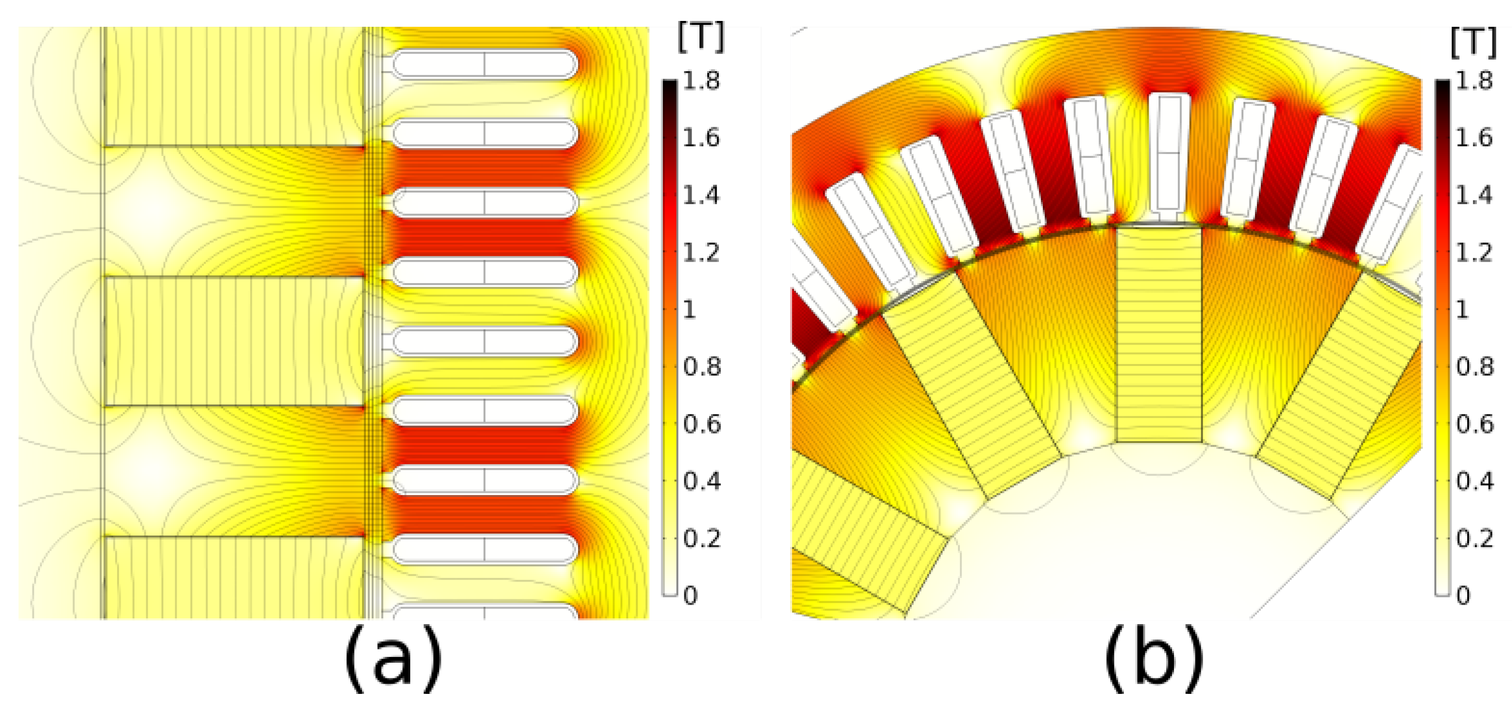
The starting point of the simulations for the buried topology is permanent magnets of rectangular blocks, where the pole shoes are extruded along the outer boundaries of the rectangular PMs. In a rotating machine, the pole shoes will arc in a circular pattern between the PMs while, in a linear machine, the pole shoes will be bound by linear lines. These are illustrated in Figure 1a,b, respectively, and are denoted the default cases. The parameter settings used for the respective machine are further detailed in Table 1.
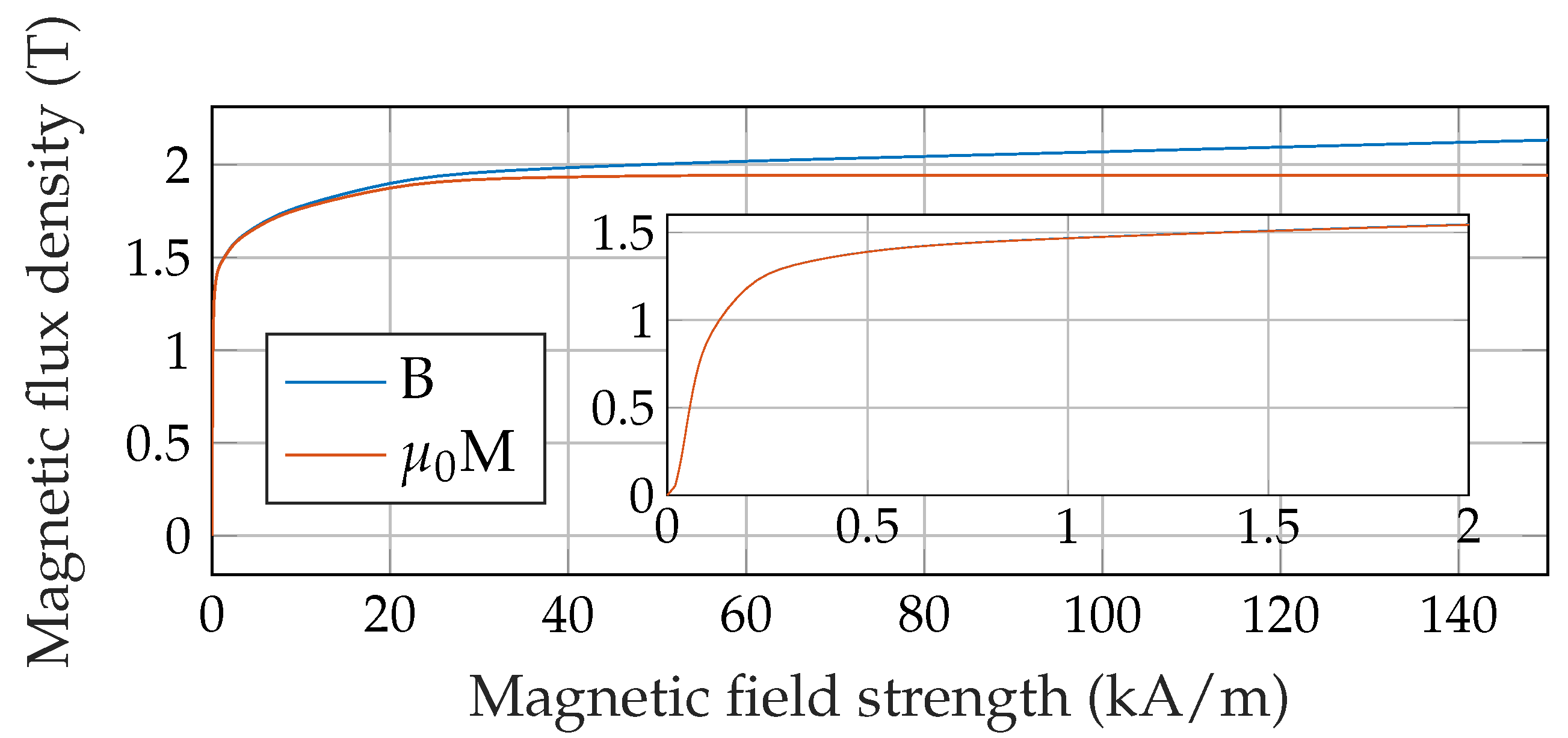
As can be seen in the table, the parameters for the linear and rotating electrical machines differ as intended, due to the different applications. The phase currents are controlled by setting the currents in-phase with the no-load voltage. This implies that the phase angle and load angle coincide, which further sets the direct current to zero. The reason for this is that the current can directly be based on the phase angle of the induced voltage, without the need to consider the terminal voltage. This can reduce the computational time remarkably and ease the convergence of the simulation. The currents are set in the q-axis of a moving reference frame and the current directions are determined based on the application: generator drive for the linear machine and motor drive for the rotating machine. In the simulations, Silicon Steel Non Grain Oriented (NGO) 50PN270 is used for the soft magnetic materials of both translator/rotor and stator. The soft magnetic material is illustrated in Figure 2. Eddy currents and hysteresis losses in the soft magnetic materials are neglected.
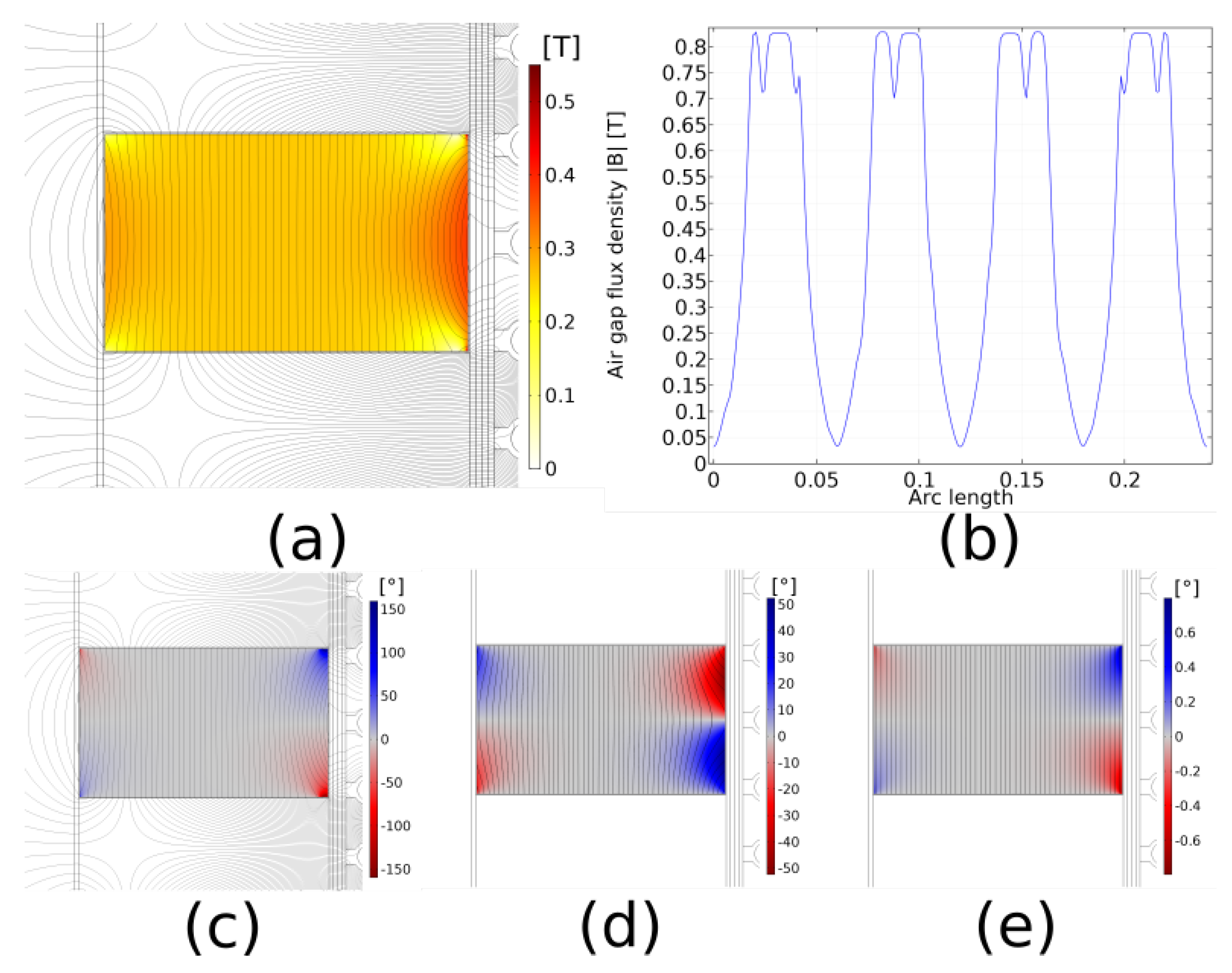
The inclination angles and magnitudes associated with the no-load default case can be seen in Figure 3.
From the figure of the no-load operation, several behaviours can be seen. In Figure 3a, the flux density is plotted. Due to the pole shoe ending at the boundary of the PMs, with no extrusion towards the air gap, the magnetic flux density is forced to change direction rapidly at the boundary between PM and pole shoe. From Figure 3b, one can see that the flux distribution is different for different stator teeth. This is due to the fractional number of slots per pole and phase. In Figure 3c, one can see that, due to the rapid change in the flux density at the boundary, some of the flux density points in the negative direction. Figure 3d and Figure 3e show the inclination angle for the magnetic field strength and magnetization, respectively. The inclination angle of the magnetic field strength is opposite due to the negative value of the self-demagnetizing field.
The averaged and maximum absolute inclination angles are further detailed in Table 2.
The magnetic flux density is continuous on the boundary between materials with different magnetic properties. The magnetization and magnetic field strength do not, however, share the same attribute. To achieve a continuous domain for the magnetization and magnetic field strength, an inner domain for the PM material is introduced. The inner domain covers 99% of the PM in the magnetization direction and should enhance the credibility of the tabulated values for the PM domain. The averaged magnitudes of the magnetic flux density in the air gap | B | ¯ a g and the RMS induced voltages are also tabulated.
Similarly, the results for the rotating machine can be seen in Table 3. Due to the high current density, the inclination angles are increased substantially. The inclination angle is further influenced by the highly saturated stator steel, which is evident by the lack of increased air gap flux density for the load case.
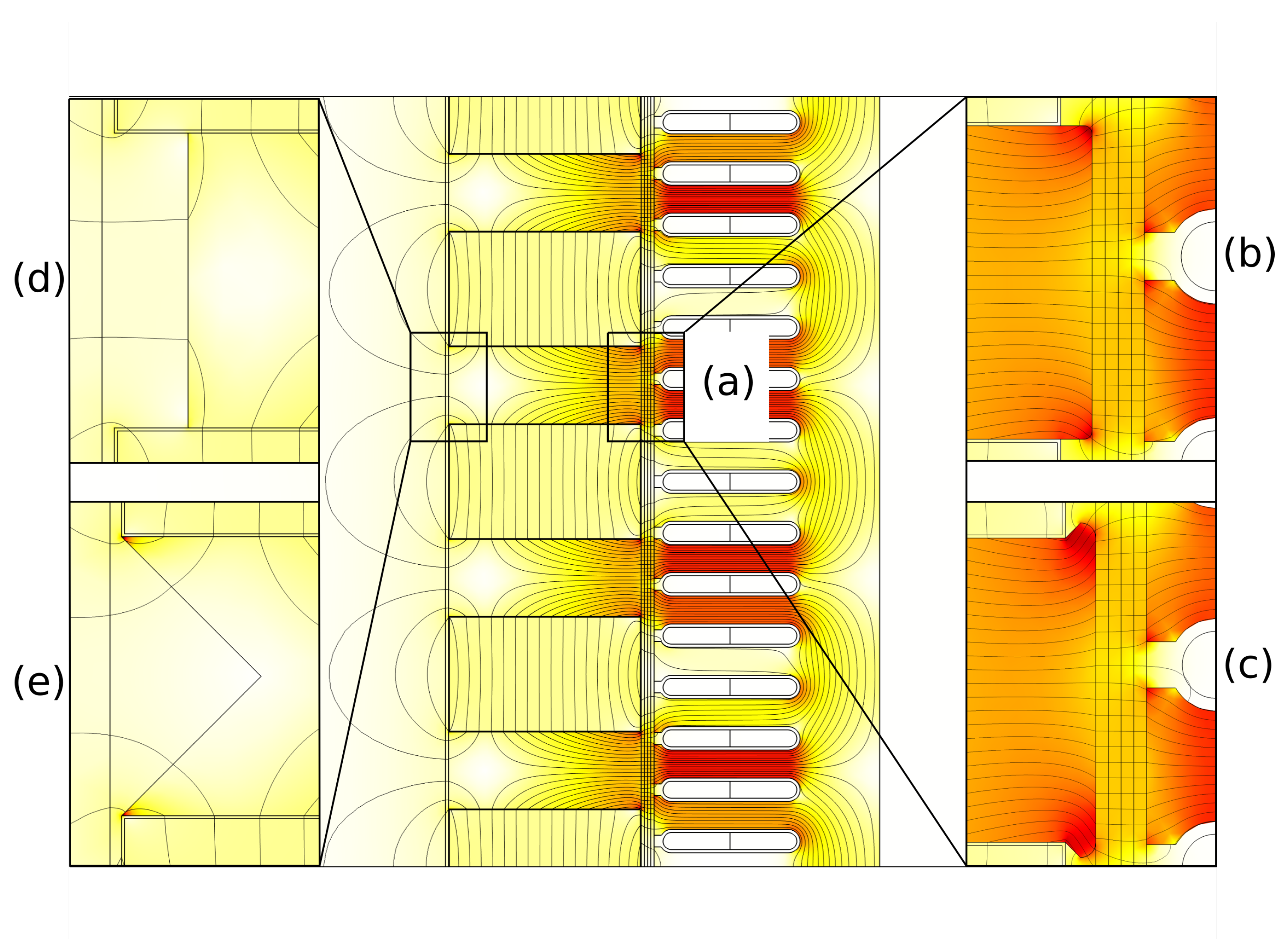
The difference in saturation level between the two topologies and applications is further visualized in Figure 4. The current density of J r m s = 2 A / mm 2 for the linear case has little impact on local saturation compared to the no-load case in Figure 1. What can be seen, however, is the slight inclination in the magnetic flux, indicated by the higher flux density on the upper slot for a specific pole. The impact of J r m s = 5 A / mm 2 for the rotating case is more severe, since the stator teeth and pole facing in the direction of the inclined magnetic flux become highly saturated. As the saturation level increases, the soft magnetic material will act more as a material with low permeability, and the flux will be less prone to passing through the soft magnetic material. Instead, an increased amount of flux will pass directly from the stator tooth, through the air gap and into the upper boundary of the PM.
The increased current density of the rotating machine sets higher demands on the implementation of inclined field behaviour. In Figure 5, different current densities are visualized for the default case without extrusions. The inclination angle of the no-load case in (a) are rather symmetric along the magnetization direction, but as the current density increases from (b) to (d), the inclination angle of the magnetic field strength increases, as well as the asymmetry.
An explanation of the high inclination angles of the magnetic field strength can be found through the origin of Ampere’s law, N I = H d l , where the magnetic field strength caused by the high current density acts against the negative magnetic field strength within the permanent magnets close to the borders of the PM in the proximity of certain regions of the air gap.
2.2. Pole Shoe Alterations

2.2.1. Linear

Four different alterations are done for the linear machine. These modifications are done in an incremental manner to the extent it is possible. These alterations are illustrated in Figure 6.
The study will include the inclination angles when the pole face is extruded, both in the air gap direction and the tangential direction, and when the pole shoe on the other end is modified, either by line- or triangular removal.

2.2.2. Rotating

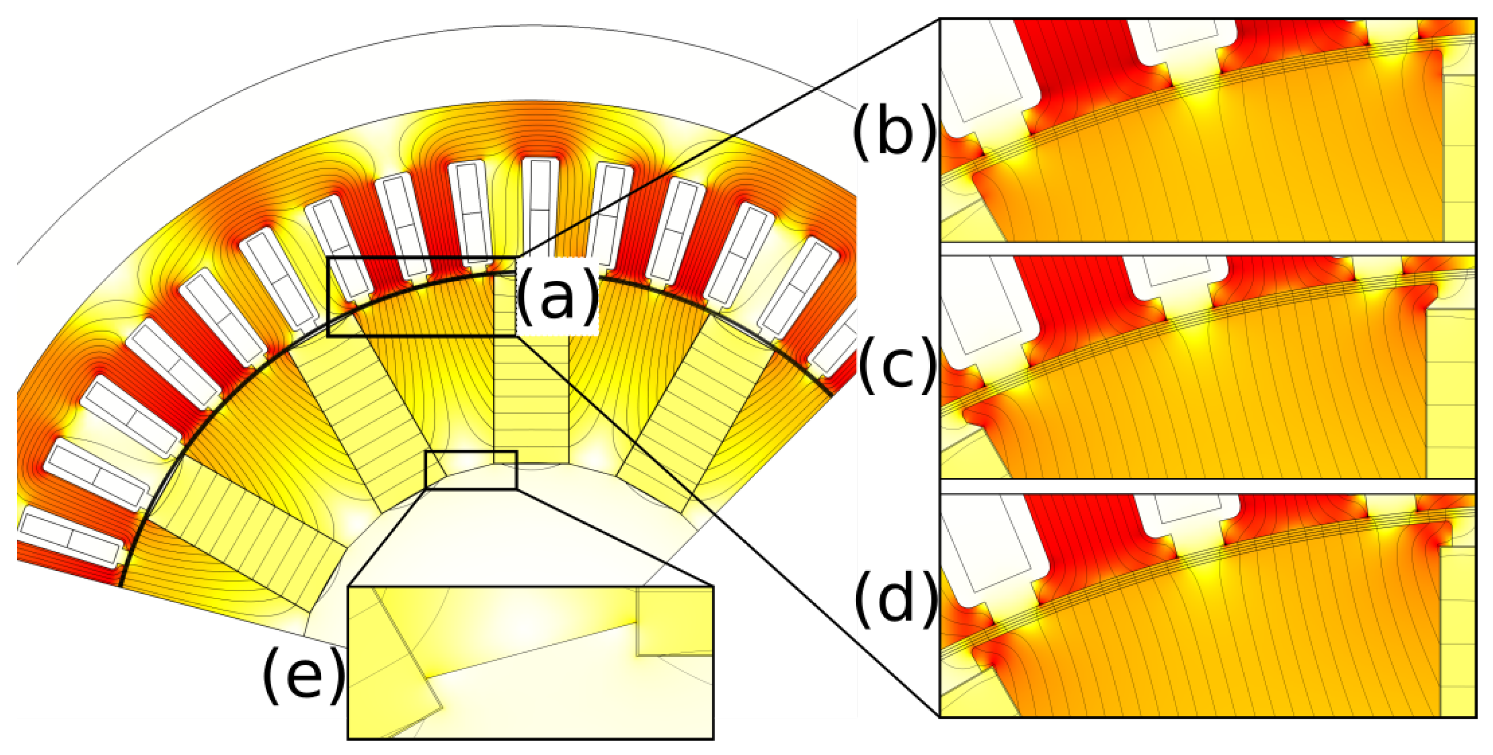
Four different alterations are also done for the rotating machine. Similar to the linear machine, the modifications to the pole shoe design are also done incrementally as far as this is possible. The study includes radially extruded pole shoes, extrusion in the tangential rotational direction with and without air between the pole face and outer PM boundary, and the inner removal of the soft magnetic material closest to the rotational axis of the rotating machine. The extruded pole shoes along the PM boundaries are common, to allow for a more sturdy frame, able to handle the centrifugal forces exerted on the PMs. The different alterations are visualized in Figure 7.

2.3. Relative Permeability Dependency

The relative permeability of the permanent magnets are often derived from the maximum energy product and the remanent flux density [9,14], as in
μ r = B r 2 4 μ 0 ( B H ) m a x
This equation assumes a linear second quadrant up to the point of the maximum energy product, located at B = B r 2 . The maximum energy product and remanent flux density are acquired for grade Y40 (e-magnetsuk.com, Grades of ferrite magnets, https://e-magnetsuk.com/ferrite-magnets/grades-of-ferrite/, accessed on 26 February 2021) and is set to 39.665 ± 2.165 [ kJ m 3 ] and 450 ± 10 [mT], respectively. This result in a relative permeability μ r = 1.016 . The relative permeability, derived from the maximum energy product, can seem quite low compared to, e.g., common values for NdFeB. Therefore, an additional study is performed to look at how changes in the relative permeability influence the angular dependency on the machine by changing μ r to 1.05. Variations in the relative permeability will influence the interdependent quantities of (1). An increased μ r will cause an increased change in the magnetization and ultimately influence the magnetic flux density.

3. Results and Discussion

3.1. Linear

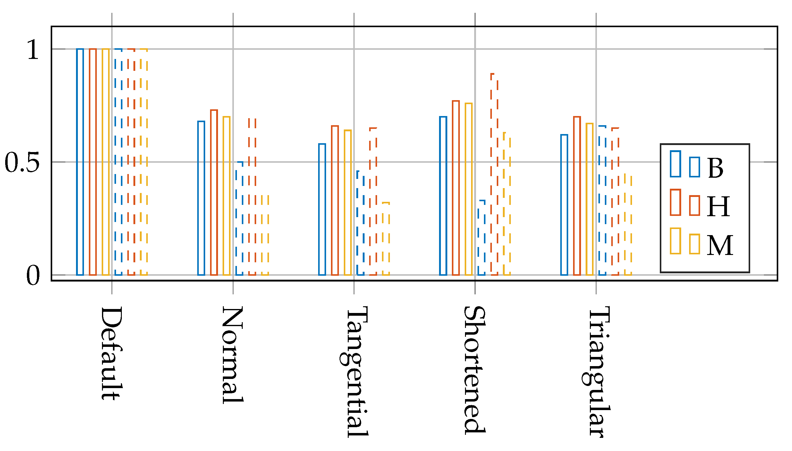
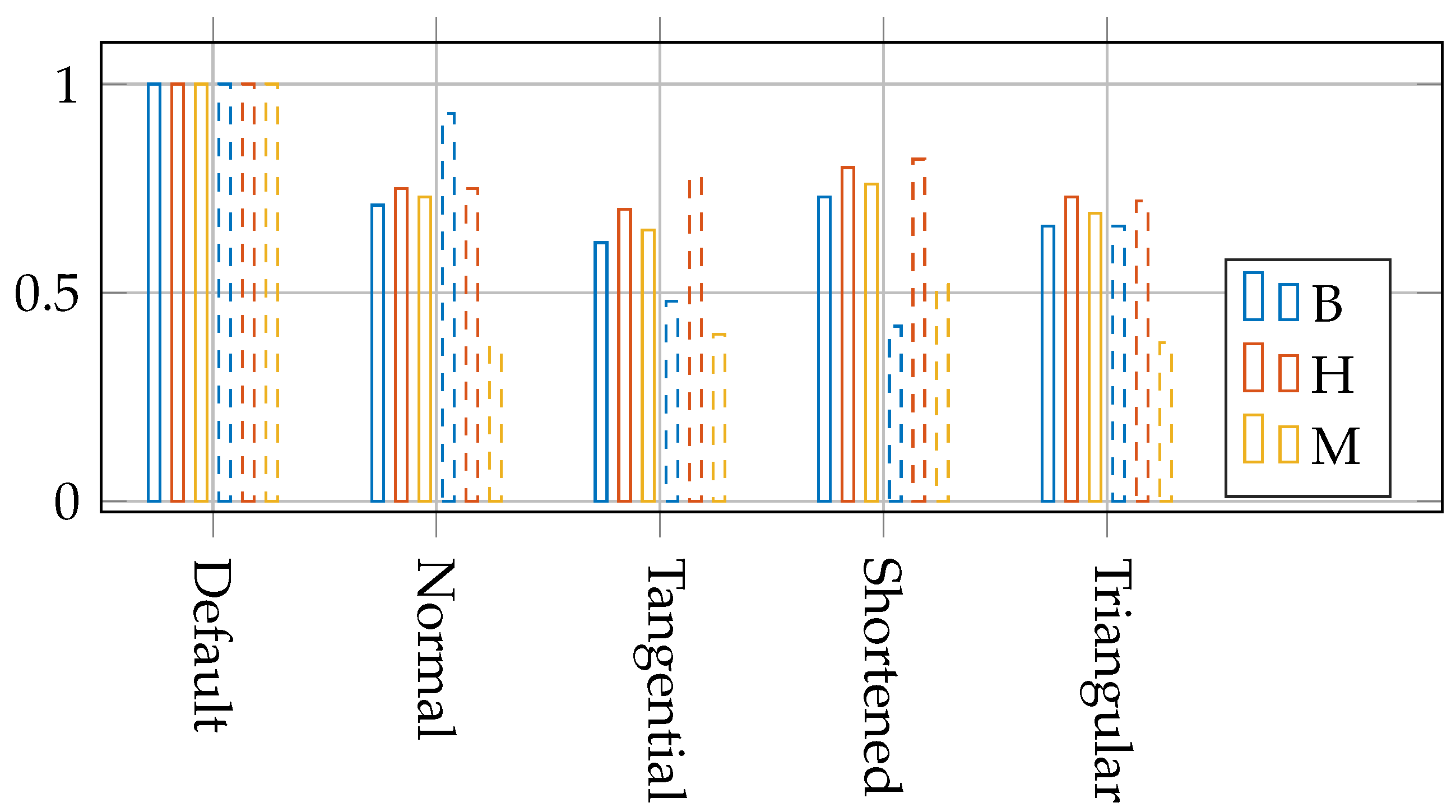
The inclination angles for the default case and the different alterations are tabulated in Table 4 for both the no-load and load cases. Furthermore, the induced no-load voltage and the averaged norm of the magnetic flux densities for no-load and load are tabulated in Table 5. The fractional dependency of the different alterations are visualized in Figure 8 and Figure 9 for the no-load and load cases, respectively.
For the extended pole face in the normal direction, or rather, the inserted position of the permanent magnets with a maintained air gap (denoted ‘Normal’), one can see that all inclination angles are reduced, compared to the ‘default case’. The maximum inclination of the magnetic flux density is reduced by 50% under no-load but only by about 10% under load. The averaged inclination angles of the magnetic flux density are reduced by around 30% for both no-load and load. The averaged values of the magnetic field strength are reduced by around 25% for both no-load and load. The maximum values of the magnetic field strength under no-load and load are reduced by around 30% and 25%, respectively, which can significantly ease the consideration for inclined behaviour of the coercive force, where it has been shown that there is little change in the coercive force up to around 30 for NdFeB [1] and, at 20 , the inclined behaviour of the irreversible demagnetization should be considered. Of course, further experimental studies for this behaviour for ferrites must be conducted to ascertain the similarity. The maximum inclination angle of the magnetization is distinctly reduced and, ultimately, so is the averaged inclination angle due to the reduced magnetic field strength in the corners. The norm of the magnetic flux density is somewhat reduced and, as a result, so are the RMS values of the induced voltage.
The extention, or overlap, of the pole face outside the permanent magnets (denoted ‘Tangential’) further reduce the inclination angle of all quantities. Furthermore, one can see that the maximum inclination angle of the magnetic flux density is significantly reduced under load due to the added flux path for the armature reaction for the tangentially extended pole shoe. The norm of the magnetic flux density in the air gap is increased to similar values as the ‘default case’ but the RMS values of the no-load voltage are still slightly lower, indicating that there is slightly more leakage flux passing through on the inner side of the stator slots.
In certain applications, the magnetic flux through the air gap can be further increased by removing some of the magnetic steel on the outer side of the translator poles, and thus forcing the flux through the air gap due to the increased reluctance on the outer side. The removal of the magnetic steel on the outer side (denoted ‘shortened’) increases the inclination angles for all quantities compared to the tangential extrusion, except for the maximum value of the magnetic flux density. Still, the average inclination angles compared to the default case is in the range of 70–80% for all quantities. The benefit of the line removal of the magnetic steel is evident in the table of the induced voltage and air gap flux density. The air gap flux densities are increased by roughly 1.5%, resulting in an increased induced phase voltage. Although the maximum fraction of the magnetic field strength (0.82) for the load case is lower than the no-load case (0.89), the maximum inclination angle of the magnetic field strength of the load case (0.82 × 58.37 = 47.86 ) is of the same size as the no-load case ( 0.89 × 53.76 = 47.85 ).
If one instead removes the triangular mid-section of the outer pole shoe (denoted ‘Triangular’), accounting for the same areal removal as the previous case, the inclination angle of the magnetic flux density is increased while the other quantities are reduced. The inclination angles of the magnetic field strength and the magnetization are slightly higher than the lowest case for the tangential extrusion, but it has the benefit of having an increased flux concentration through the air gap and, ultimately, higher induced voltage.
Recalling the increased need for consideration of inclination angles above 20 [1] for NdFeB, the PM area fraction for which the inclination angle of the magnetic field strength that exceeds 20 is, for the default case, at a maximum 6.4% and 7.4% for no-load and load, respectively. These are reduced to a maximum of 2.3% and 3.3% for the tangential pole shoe design for no-load and load, respectively. The specific value of 20 is used only as a frame of reference, to give an indication of the increased complexity of appropriate PM modelling, when subjected to inclined fields. Together with the maximum inclination angles, indicating local inclinations and the averaged inclination angles, indicating the overall inclination of the PM, this frame of reference adds to the description of how well different pole shoe alterations perform.

3.2. Rotating

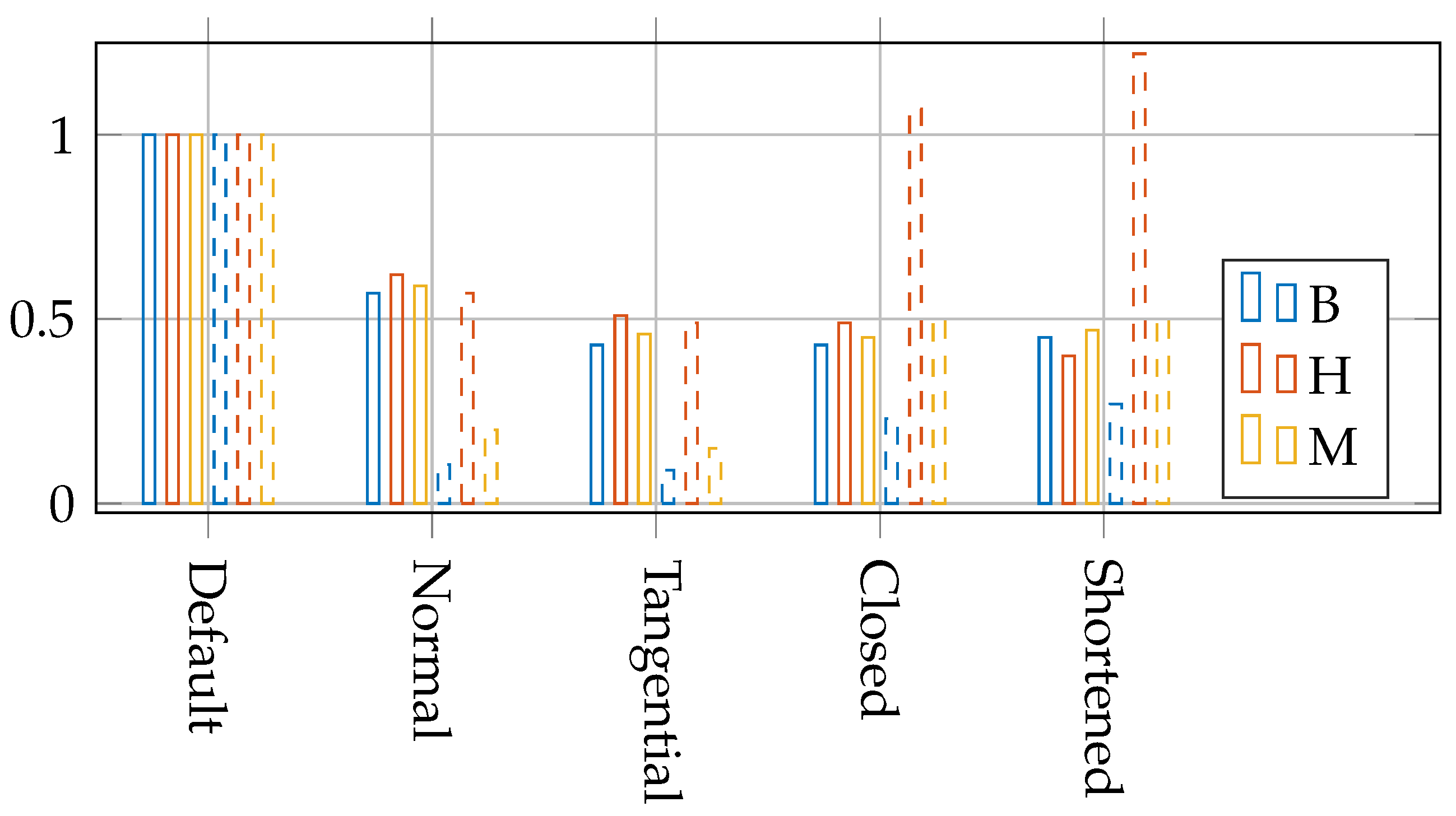
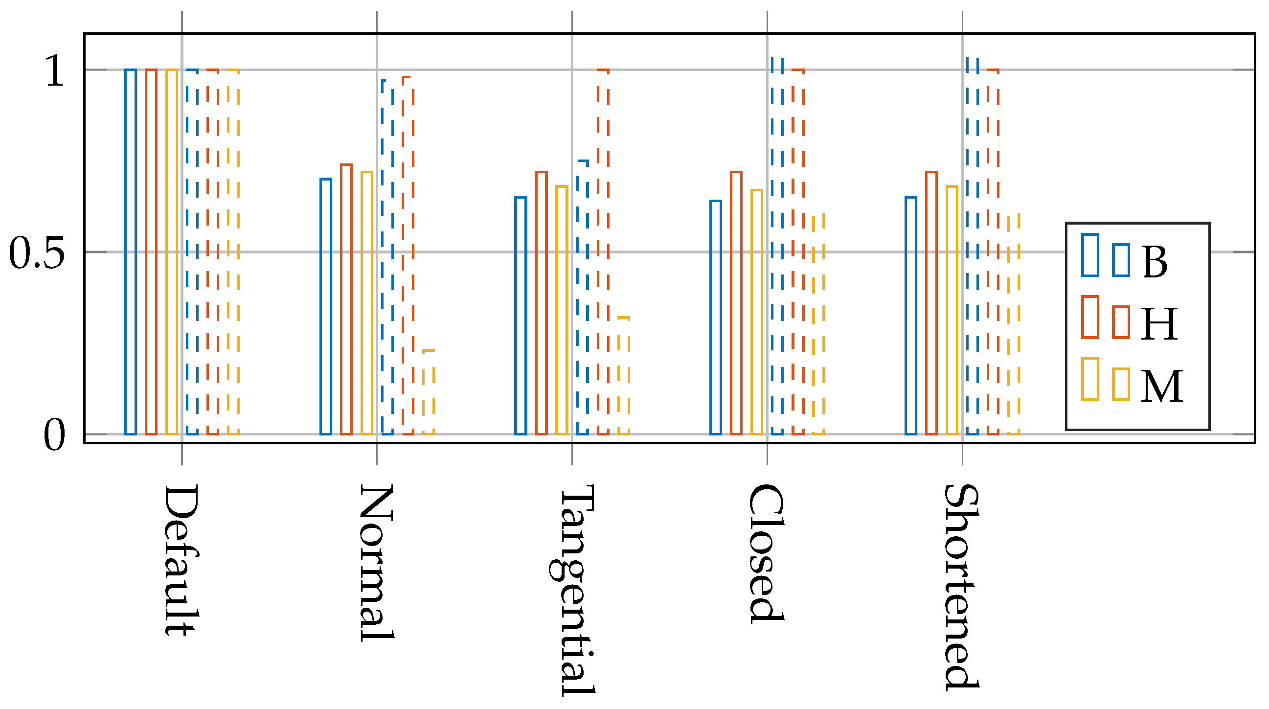
Similarly, the table for the inclination angles for the rotating machine can be seen in Table 6 for the no-load and load cases. Induced no-load volage and the averaged norm of the magnetic flux densities are futher tabulated in Table 7. The fractional dependency of the different alterations are visualized in Figure 10 and Figure 11 for the no-load and load cases, respectively.
The extended pole shoes in the normal (radial) direction (denoted ‘Normal’) reduce the inclination angles significantly for both the no-load averaged and maximum values. Under load, however, the maximum values for the magnetic field inclination angle remain high, due to the armature reaction from the high current density of 5 A / mm 2 . The PM area fraction for which the inclination angle of the magnetic field strength that exceeds the threshold of 45 is 4.72% and 20 is 12.9%, compared to the default case of 7.85% and 16.7%. Similarly, the averaged inclination angles are reduced by 20–30%. Due to the remaining high averaged inclination angle, effort should be put into modelling the inclined field behaviour.
The tangential extrusion (denoted ‘Tangential’) further reduces the inclination angles for the no-load case slightly. Under load, however, the inclination remains high. The PM area fraction for which the inclination angle of the magnetic field strength that exceeds the threshold of 45 is 4.48% and 20 is 12.4%, which are slightly lower than the case for normal extrusion.
By tangentially extruding the pole face along the PM border (denoted ‘Closed’) one can better cope with the mechanical stresses due to the centrifugal forces of the PMs in the rotor. By doing so, the averaged inclination is reduced compared to the default case with no extrusion. Even though the averaged values are reduced, one does introduce local high inclined fields, indicated by the no-load case. Since the maximum inclination angle under load is already high and the averaged inclination is reduced compared to the default case, this pole shoe design can still serve as a good alternative when the mechanical stresses are a priority. The PM area fraction for which the inclination angle of the magnetic field strength that exceeds the threshold of 45 is 4.42% and 20 is 12.2%, which is lower than the previous cases.
Due to the inherent concentration of the magnetic flux towards the air gap for rotating machine and further benefitting from the small air gap, and thus lower reluctance path, the need for removal of the inner pole shoe segment (denoted ‘Shortened’) is lessened. This is evident in the negligible change in flux passing through the air gap for the case where the inner segment is removed. The PM area fraction for which the inclination angle of the magnetic field strength that exceeds the threshold of 45 is 4.39% and 20 is 12.4%.
As mentioned, the current density plays a major role in the inclination angle of the motor drive topology. At the air gap boundary of the PMs, the magnetic field strength of the armature reaction acts opposite the self-demagnetizing field of the PMs. If the current density is reduced by 20% to 4 A / mm 2 for the tangential extrusion alteration, the inclination of the magnetic field strength can be reduced to 76.63 and 5.73 for the maximum and averaged values, respectively. Despite the significant reduction in the maximum value, the area fraction of the PM domain that exceeds 20 can be as high as 10% of the PM.
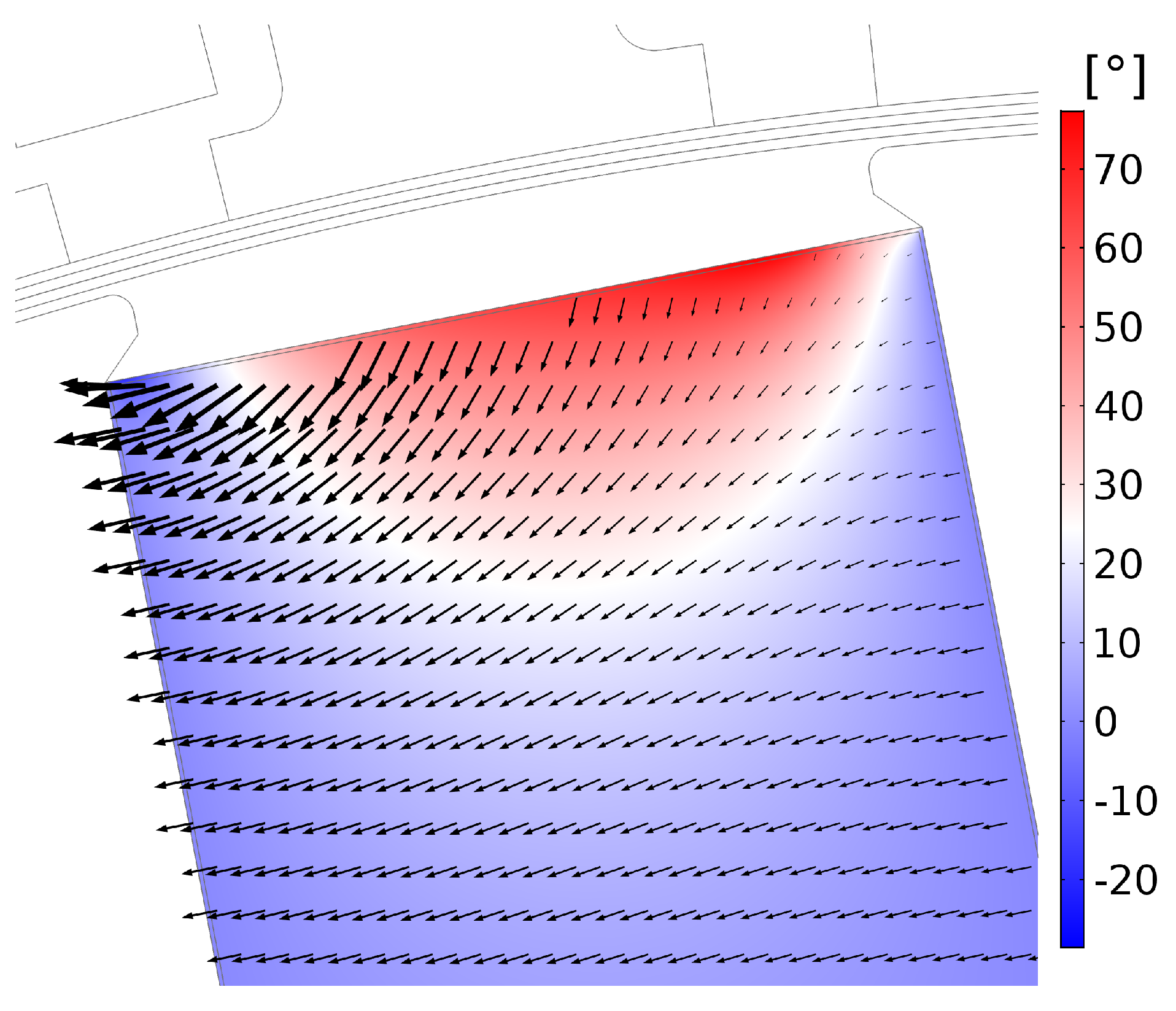
It should be noted, however, that the inclination angle in itself does not necessarily directly correspond to increased risk of irreversible demagnetization. In fact, a 180 reversal in the magnetic field strength indicates that the magnetic field strength is positive in the BH-curve. In the region of reversed magnetic field strength in the simulations, the magnitude of the magnetic field strength is very low and the magnetic flux density is close to the remanent flux density. It should be stressed that high magnetic field strength associated with inclined angles requires more extensive effort to account for irreversible demagnetization. In Figure 12, a vector plot (arrows) and the inclination angles (colored) for the magnetic field strength H in the PM are shown for one rotor position. It can be seen that the maximum inclination angle and maximum magnitude are located on opposite sides of the PM boundary towards the air gap.

3.3. Relative Permeability Dependency

The no-load inclination angle dependencies for the different quantities due the change in relative permeability are tabulated in Table 8 and Table 9 for the linear and rotating machine, respectively. Increasing the relative permeability increases the change in magnetization due to the magnetic field strength. As a result, the magnetization angle is increased. By changing the relative permeability from μ r = 1.016 to μ r = 1.05 , the averaged and maximum inclination angles of the magnetization are increased by roughly a factor of 3 for both the linear and rotating machines. The inclination angles for the magnetic field strength are slightly reduced and the spatial difference between H and M remains almost the same. The inclination angles of the magnetic flux density are also of similar values.
Due to the small changes in the inclination angle of magnetic field strength and magnetic flux density with relative permeability, the inclination angle dependency of the pole shoe alterations are less restricted to specific values of the relative permeability.
For the generator application, which typically has a lower current density than the motor drive counterpart, the inclination angles can be controlled by modifying the pole shoes. This can both increase the performance and increase the accuracy of modelling for a broader variety of relative permeability values, when simpler models of irreversible demagnetization are considered.
The inclination angles can also be controlled for the motor drive application for varied relative permeability values, but, due to the high inclinations caused by the increased current density, more caution must be taken for the inclined field behaviour of irreversible demagnetization if the PMs are to be accurately modelled.

4. Conclusions

It is clear that the magnitudes and inclination angles of B, M and H are greatly influenced by the design of all soft magnetic components in an electrical machine. Since the inclination also differs substantially between, e.g., the magnetic flux density and the magnetic field strength, it is also of importance to keep this in mind when looking at certain directional components for the risk assessment of irreversible demagnetization.
Through a proper design of the soft magnetic material in the electrical machine, one can both reduce the stresses of irreversible demagnetization and achieve higher credibility of the simulations of the permanent magnet performance.
The performed study shows, overall, very small changes in the induced voltage and the flux density in the air gap due to the pole shoe design alterations. Both of these are common when trying to increase the performance through FE simulations. Considering the small change in flux density and voltage, and substantial effect on the inclination angles, the study of how the magnets are affected by the pole shoes is important.
The requirement for increased current densities for the motor drive application sets further demands on the accuracy of the permanent magnet modelling, due to the substantially higher inclination angles of the magnetic field strength.
The extended survey on the impact of recoil permeability show minor changes to the inclination angle of the magnetic flux density and magnetic field strength due to the changes in magnetization. Therefore, these considerations of inclination angle are likely general for most applications for rare-earth free machines of buried topology.

Author Contributions

This was a collaborative work between J.S. and S.E. J.S. designed and performed the simulations and wrote most of the paper. S.E. contributed significantly to the analysis of the results and the revision of the text. All authors have read and agreed to the published version of the manuscript.

Funding

The research was funded by Uppsala University and the Swedish strategic research program StandUp for Energy.

Conflicts of Interest

The authors declare no conflict of interest. The funders had no role in the design of the study; in the collection, analyses, or interpretation of data; in the writing of the manuscript, or in the decision to publish the results.

References

  1. Ruoho, S.; Arkkio, A. Partial Demagnetization of Permanent Magnets in Electrical Machines Caused by an Inclined Field. IEEE Trans. Magn. 2008, 44, 1773–1778. [Google Scholar] [CrossRef]
  2. Galioto, S.J.; Reddy, P.B.; EL-Refaie, A.M. Effect of magnet types on performance of high speed spoke interior permanent magnet machines designed for traction applications. In Proceedings of the 2014 IEEE Energy Conversion Congress and Exposition (ECCE), Pittsburgh, PA, USA, 14–18 September 2014; pp. 4513–4522. [Google Scholar] [CrossRef]
  3. Ranlöf, M.; Lundin, U. Form Factors and Harmonic Imprint of Salient Pole Shoes in Large Synchronous Machines. Electr. Power Compon. Syst. 2011, 39, 900–916. [Google Scholar] [CrossRef]
  4. Evans, S.A. Salient pole shoe shapes of interior permanent magnet synchronous machines. In Proceedings of the XIX International Conference on Electrical Machines—ICEM 2010, Rome, Italy, 6–8 September 2010; pp. 1–6. [Google Scholar] [CrossRef]
  5. Hague, B. The shape of pole-shoe required to produce a sinusoidal distribution of air-gap flux density. J. Inst. Electr. Eng. 1924, 62, 921–929. [Google Scholar] [CrossRef]
  6. Rasilo, P.; Belahcen, A.; Arkkio, A. Effect of rotor pole-shoe construction on losses of inverter-fed synchronous motors. In Proceedings of the 2012 XXth International Conference on Electrical Machines, Marseille, France, 2–5 September 2012; pp. 1282–1286. [Google Scholar] [CrossRef]
  7. Zhang, G.; Yu, W.; Hua, W.; Cao, R.; Qiu, H.; Guo, A. The Design and Optimization of an Interior, Permanent Magnet Synchronous Machine Applied in an Electric Traction Vehicle Requiring a Low Torque Ripple. Appl. Sci. 2019, 9, 3634. [Google Scholar] [CrossRef] [Green Version]
  8. Eklund, P.; Eriksson, S. The Influence of Permanent Magnet Material Properties on Generator Rotor Design. Energies 2019, 12, 1314. [Google Scholar] [CrossRef] [Green Version]
  9. Sjökvist, S.; Eriksson, S. Investigation of Permanent Magnet Demagnetization in Synchronous Machines during Multiple Short-Circuit Fault Conditions. Energies 2017, 10, 1638. [Google Scholar] [CrossRef] [Green Version]
  10. Xiong, H.; Zhang, J.; Degner, M.W.; Rong, C.; Liang, F.; Li, W. Permanent-Magnet Demagnetization Design and Validation. IEEE Trans. Ind. Appl. 2016, 52, 2961–2970. [Google Scholar] [CrossRef]
  11. Tizianel, S.; Novello, N. Permanent Magnet Demagnetization Process Considering the Inclination of the Demag Field. IEEE Trans. Magn. 2016, 52, 1–7. [Google Scholar] [CrossRef]
  12. Souza, M.; Vidigal, C.; Momy, A.; Taquin, J.; Sauzade, M. Nonlinear calculation of three-dimensional static magnetic fields. IEEE Trans. Magn. 1997, 33, 2486–2491. [Google Scholar] [CrossRef]
  13. Sjölund, J.; Leijon, M.; Eriksson, S. Method for optimizing the magnetic circuit of a linear generator using FEM simulations. AIP Adv. 2020, 10, 035312. [Google Scholar] [CrossRef]
  14. Eklund, P.; Eriksson, S. Air gap magnetic flux density variations due to manufacturing tolerances in a permanent magnet synchronous generator. In Proceedings of the 2016 XXII International Conference on Electrical Machines (ICEM), Lausanne, Switzerland, 4–7 September 2016; pp. 93–99. [Google Scholar] [CrossRef]
Figure 1. The no-load default cases for the linear and rotating electrical machines in (a,b), respectively.
Energies 14 02437 g001
Figure 2. The BH-curve for the soft magnetic material, Silicon Steel NGO 50PN270 used in the simulations. As can be seen in the zoomed-in version, the hysteresis is not considered in the study.
Energies 14 02437 g002
Figure 3. Different components and directions of B, H and M from B = μ 0 ( H + M ) of the linear default case. (a,b) shows the magnetic flux density magnitude in the PMs and air gap, respectively. (ce) shows the inclination angles of the magnetic flux density B, magnetic field strength H and magnetization M, respectively.
Energies 14 02437 g003
Figure 4. Magnetic flux density for the linear and rotating default cases under load in (a,b), respectively. The lower current density of J r m s = 2 A / mm 2 of the linear machine will cause an inclination of the magnetic flux in the stator, but less increase in saturation. The higher current density of J r m s = 5 A / mm 2 for the rotating machine will cause high local saturation, causing an increased amount of magnetic flux entering the PM on the upper boundary.
Energies 14 02437 g004
Figure 5. Inclination angle of the magnetic field strength, H, for different current densities. The current densities J r m s in (ad) is 0 A / mm 2 , 2 A / mm 2 , 3.5 A / mm 2 and 5 A / mm 2 , respectively.
Energies 14 02437 g005
Figure 6. Different alterations to the linear electrical machine. The different design alterations from (ae) are denoted Default, Normal, Tangential, Shortened and Triangular, respectively.
Energies 14 02437 g006
Figure 7. Different alterations of the rotating electrical machine. The different design alterations from (ae) are denoted Default, Normal, Tangential, Closed and Shortened, respectively.
Energies 14 02437 g007
Figure 8. No-load fractional dependency of the inclination angles due to changed pole shoe design for the linear machine. Solid bars indicate the averaged fractional values and the dashed bars indicate the maximum fractional values, both also tabulated in Table 4.
Energies 14 02437 g008
Figure 9. Fractional dependency of the inclination angles due to changed pole shoe design for the linear machine under load. Solid bars indicate the averaged fractional values and the dashed bars indicate the maximum fractional values, both also tabulated in Table 4.
Energies 14 02437 g009
Figure 10. No-load fractional dependency of the inclination angles due to changed pole shoe design for the rotating machine. Solid bars indicate the averaged fractional values and the dashed bars indicate the maximum fractional values, both also tabulated in Table 6.
Energies 14 02437 g010
Figure 11. Fractional dependency of the inclination angles due to changed pole shoe design for the rotating machine under load. Solid bars indicate the averaged fractional values and the dashed bars indicate the maximum fractional values, both also tabulated in Table 6.
Energies 14 02437 g011
Figure 12. Vector plot (arrows) and the inclination angles (colored) for the magnetic field strength H in a PM for one rotor position with a current density J r m s = 4 A / mm 2 . The maximum inclination angle and maximum magnitude appear on opposite sides of the PM boundary towards the air gap.
Energies 14 02437 g012
Table 1. Machine parameters.
LinearRotating
Fill factor70%52%
PM width60 [mm]50 [mm]
PM height36 [mm]20 [mm]
Pole pitch60 [mm]58.9 [mm]
Current density (RMS)2 [ A / mm 2 ]5 [ A / mm 2 ]
Air gap length4 [mm]1 [mm]
Radius, rotor-112.5 [mm]
stator yoke24.8 [mm]15 [mm]
Rotor pole pairs-6
Stator teeth factor52.625%50%
B r 0.45 [T]0.45 [T]
μ r 1.0161.016
Pole face fraction40%66%
Soft magn. materialSilicon Steel NGO 50PN270
Table 2. The averaged and maximum angular dependency of magnetic flux density, B, magnetic field strength, H, and magnetization, M, for the default case of the linear machine, denoted ang(). The averaged magnitude of the air gap flux density for no-load and load, and the no load RMS voltage are also tabulated.
No-Load Load
AverageMaximumAverageMaximum
ang (B) 3.85 161.33 4.32 166.67
ang (H) 4.78 53.76 5.28 58.37
ang (M) 0.033 0.87 0.037 1.06
ang (H-M) 4.82 54.09 5.32 58.69
| B | ¯ a g 0.458 [T] 0.461 [T]
V r m s 7.24
Table 3. The averaged and maximum angular dependency of magnetic flux density, B, magnetic field strength, H, and magnetization, M, for the default case of the rotating machine, denoted ang(). The averaged magnitudes of the air gap flux density for no-load and load, and the no load RMS voltage are also tabulated.
No-Load Load
AverageMaximumAverageMaximum
ang (B) 1.145 150.72 3.41 172.83
ang (H) 3.798 70.99 9.43 179.999
ang (M) 0.0135 0.881 0.0379 2.234
ang (H-M) 3.811 71.20 9.47 179.999
| B | ¯ a g 0.586 [T] 0.585 [T]
V r m s 84.4
Table 4. Angular dependency of magnetic flux density B, magnetic field strength H and magnetization M for the linear machine due to pole shoe alterations under no-load and load. For the design alterations, the inclination angels are given as a fraction of the respective inclination angle for the default case. The pole shoe alterations are illustrated in Figure 6.
No-LoadLoad
DefaultNormalTangentialShortenedTriangularDefaultNormalTangentialShortenedTriangular
AvgMaxAvgMaxAvgMaxAvgMaxAvgMaxAvgMaxAvgMaxAvgMaxAvgMaxAvgMax
B 3.85 161 0.680.50.580.460.700.330.620.66 4.32 167 0.710.930.620.480.730.420.660.66
H 4.78 53.8 0.730.700.660.650.770.890.700.65 5.28 58.4 0.750.750.700.780.800.820.730.72
M 0.033 0.87 0.70.360.640.320.760.630.670.45 0.037 1.06 0.730.370.650.400.760.520.690.38
H-M 4.82 54.1 0.730.700.660.650.770.890.700.65 5.32 58.7 0.750.750.700.780.800.820.730.72
Table 5. Induced voltage and air gap flux density magnitude for the linear machine under no-load (NL) and load.
DefaultNormalTangentialShortenedTriangular
V r m s , N L 7.247.117.187.317.25
| B | ¯ a g , N L 0.458 [T]0.450 [T]0.458 [T]0.466 [T]0.462 [T]
| B | ¯ a g , L o a d 0.4610.452 [T]0.460 [T]0.468 [T]0.465 [T]
Table 6. Angular dependency of magnetic flux density B, magnetic field strength H and magnetization M for the rotating machine due to pole shoe alterations under no-load and load. For the design alterations, the inclination angels are given as a fraction of the respective inclination angle for the default case. The pole shoe alterations are illustrated in Figure 7.
No-LoadLoad
DefaultNormalTangentialClosedShortenedDefaultNormalTangentialClosedShortened
AvgMaxAvgMaxAvgMaxAvgMaxAvgMaxAvgMaxAvgMaxAvgMaxAvgMaxAvgMax
B 1.15 151 0.570.110.430.090.430.230.450.27 3.41 173 0.700.970.650.750.641.040.651.04
H 3.80 71.0 0.620.570.510.490.491.070.491.22 9.43 180 0.740.980.721.000.721.000.721.00
M 0.014 0.88 0.590.200.460.150.450.500.470.50 0.038 2.23 0.720.230.680.320.670.610.680.61
H-M 3.81 71.2 0.620.570.510.490.491.040.491.21 9.47 180 0.740.980.721.000.721.000.721.00
Table 7. Induced voltage and air gap flux density magnitude for the rotating machine under no-load(NL) and load.
DefaultNormalTangentialClosedShortened
V r m s , n o l o a d 84.484.083.383.283.3
| B | ¯ a g , N L 0.586 [T]0.581 [T]0.586 [T]0.586 [T]0.587 [T]
| B | ¯ a g , L o a d 0.585 [T]0.580 [T]0.586 [T]0.586 [T]0.587 [T]
Table 8. No-load angular dependency for B, M and H for different relative permeability values for the linear machine. For the design alterations, the inclination angles are given as a fraction of the respective inclination angle for the default case. The pole shoe alterations are illustrated in Figure 6.
μ r = 1.016 μ r = 1.05
DefaultNormalTangentialShortenedTriangularDefaultNormalTangentialShortenedTriangular
AvgMaxAvgMaxAvgMaxAvgMaxAvgMaxAvgMaxAvgMaxAvgMaxAvgMaxAvgMax
B 3.85 161 0.680.50.580.460.700.330.620.66 3.92 162 0.680.510.560.470.700.340.620.67
H 4.78 53.8 0.730.700.660.650.770.890.700.65 4.71 53.2 0.730.690.660.650.770.900.700.65
M 0.033 0.87 0.70.360.640.320.760.630.670.45 0.102 2.77 0.710.350.620.310.750.610.660.44
H-M 4.82 54.1 0.730.700.660.650.770.890.700.65 4.82 54.2 0.730.690.660.650.660.910.700.65
Table 9. No-load angular dependency for B, M and H for different relative permeability values for the rotating machine. For the design alterations, the inclination angles are given as a fraction of the respective inclination angle for the default case. The pole shoe alterations are illustrated in Figure 7.
μ r = 1.016 μ r = 1.05
DefaultNormalTangentialClosedShortenedDefaultNormalTangentialClosedShortened
AvgMaxAvgMaxAvgMaxAvgMaxAvgMaxAvgMaxAvgMaxAvgMaxAvgMaxAvgMax
B 1.15 151 0.570.1050.430.090.430.230.450.27 1.17 151 0.560.110.430.090.420.230.450.27
H 3.80 71.0 0.620.570.510.490.491.070.491.22 3.76 70.6 0.610.560.500.490.491.080.491.23
M 0.014 0.88 0.590.200.460.150.450.500.470.50 0.042 2.80 0.590.190.460.140.450.490.460.49
H-M 3.81 71.2 0.620.570.510.490.491.040.491.21 3.80 71.2 0.610.560.500.490.491.080.491.21
Publisher’s Note: MDPI stays neutral with regard to jurisdictional claims in published maps and institutional affiliations.