1. Introduction
The centrifugal pump has been widely used as essential and effective equipment in the hydraulic transportation of solids. In the pumping process, the solid particles carried by the fluid stream would cause considerable erosion due to abrasive and impact wear on the flow parts’ surface [
1], which determines the operational life and the reliability of slurry pumps. Theoretically, abrasive wear occurs when particles slide against equipment surfaces, while impact wear occurs when particles’ impact equipment surfaces. For many years, the results of the experiment and numerical simulation have been carried out to predict and reveal the erosion due to wear in centrifugal pumps. The wear distribution and rates were assessed in a centrifugal pump impeller through a wear test rig by Tao et al. [
2]. They concluded that the areas with severe wear in impeller passages are located at the blade leading edge, hub surface, and pressure side. Ahmad et al. [
3] developed a computer program with an impact wear model to study the wear of a centrifugal pump impeller and validate the results by the paint wear experiment. They pointed out that the maximum wear happened on the blade leading edge and hub. Lei et al. [
4] numerically analyzed the wear on blade surfaces by a Eulerian-Lagrangian method with an impact wear model. Results showed that the impact wear of the blade pressure side is more severe than that of the suction side. Noon et al. [
5] utilized a similar numerical method to compare the numerical wear with experimental data in a centrifugal pump and demonstrated that the volute would be the most affected regions of impact wear damage. In addition, the effects of particle size, slurry concentration, and particle velocity on the wear rate were investigated. Unlike the numerical methods above, Huang et al. [
6] applied a Computational Fluid Dynamics (CFD)-Discrete Element Method (DEM) coupling method with an abrasive wear model to study the wear in a centrifugal pump quantitatively. Results claimed that the number of particle collisions with flow parts mainly proportionally followed the wear loss on each part. Generally, these numerical methods treated the particles as a sphere and solely adopted one wear model to obtain the wear. However, the particle shapes have an essential influence on the wear characteristics [
7]. Moreover, no previous study has investigated the abrasive and impact wear simultaneously in the centrifugal pump, which cannot provide a reliable prediction for the wear law. Therefore, this paper aims to compare the abrasive and impact wear characteristics of flow parts in a centrifugal pump and explore the relationship between wear and particle shape.
As an alternative, the DEM is a competent numerical approach to analyze particle systems. Moreover, Tsuji et al. [
8] and Kafui et al. [
9] developed a CFD-DEM coupling method in order to enhance the numerical precision in calculating multiphase flow. More importantly, with increasing attention on particle shape relevance in collision behavior and flow interactions [
10,
11,
12], the multi-shaped particle modeling has been developed into various forms in the DEM. On the other hand, the abrasive and impact wear, which are two broad categories of wear erosion due to particle interactions, can be numerically achievable in the DEM. Hence, the results of abrasive and impact wear can be obtained simultaneously and analyzed separately for comparison.
According to these above, a comparative analysis of abrasive and impact wear on flow parts of a centrifugal pump was examined for the first time via the CFD-DEM coupling method, which takes full account of the particle shapes. A DEM code analyzed the particle distribution and motion combined with two wear erosion models based on a commercial platform STAR-CCM+. Furthermore, four regular polyhedral particles (tetrahedron, hexahedron, octahedron, and dodecahedron) and one sphere particle were mainly modeled to investigate the impact of particle shapes on the wear rate. These results would provide new insights into the wear research in the centrifugal pump, which may benefit optimization design for a centrifugal pump.
2. Methodology
2.1. Geometric Model and Mesh
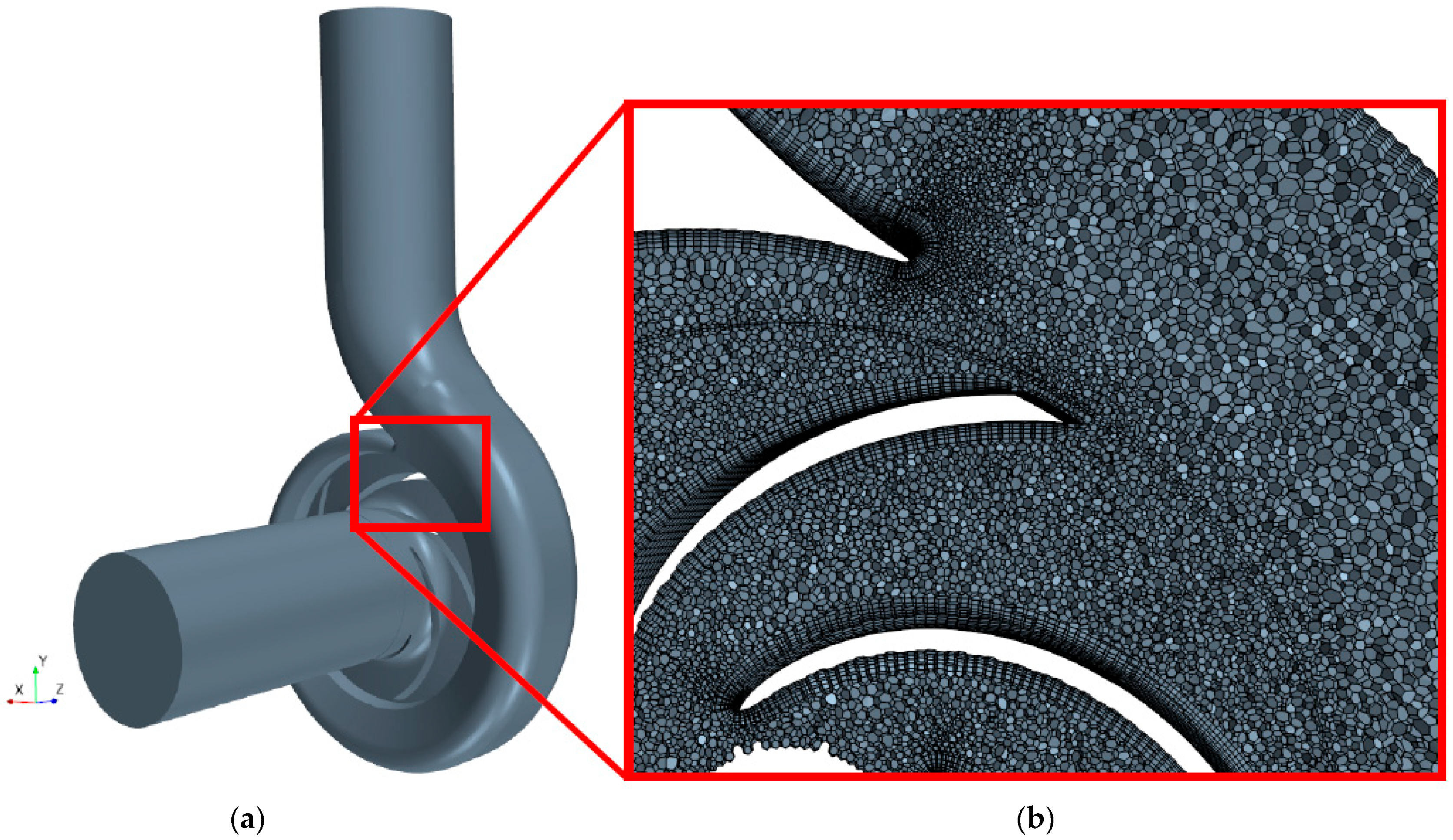
In this paper, a centrifugal pump geometric model involving an inlet pipe, impeller, and volute was built for calculating the wear, as shown in
Figure 1a. For validating the numerical method, the computational domain holds the same geometry as the original pump provided by one of the pump companies in China. The design flow rate of the pump is 68.4 m
3/h with a head of 8.3 m, under a 1450 rpm rotation speed. The diameters of the pump inlet, impeller, and pump outlet are 115 mm, 190 mm, and 100 mm, respectively. The polyhedron meshes of the computational domain and five prism layers at the wall boundaries (see
Figure 1b) were created. To ensure the slight influence of mesh number on the results, the pump head was employed to test the mesh independence, as shown in
Table 1. It is apparent from this table that there is a slight change in the pump head when the mesh number is bigger than 1,255,663. Thus, the mesh number was set as 1,255,663 for subsequent simulations.
2.2. Governing Equations of Solid-Liquid
In the CFD-DEM modeling of this work, the liquid phase is assumed to be a macro-scaled continuum, and the governing equations of the liquid phase according to the mass and momentum conservation are shown by the following equation.
Mass conservation equation:
Momentum conservation equation:
where scalars
t,
ρf,
x,
u,
p, and
μeff are the time, fluid density, coordinates, fluid velocity, fluid pressure, and fluid effective viscosity, respectively. The vectors
g,
Fdrag Fsl, and
Fpg denote the gravity and particles-liquid interaction forces, namely the drag force, Saffman’s lift force, and pressure gradient force. Furthermore,
αf is the fluid volume fraction in each cell, which is also called porosity or void fraction. All the particle centers are assumed to be located in a selected computational cell, and
αf can be estimated through the equation:
where
n is the number of particles within the selected cell and
Vp,i denotes the volume of particle
i within the computational cell.
Vcell is the cell volume.
The translational motion of the solid particles is governed by Newton’s second law, while the rotational motion of the particles is controlled by Euler’s second law in DEM. The main governing equations for particles in the pump are shown by the following.
where the scalar m is the particle mass, while the vector
I denotes the moment of inertia of the particle. The
dv/
dt and
dω/
dt are translational and angular acceleration of the particle. The vector
Fc denotes the collisional forces of a particle with other particles or wall boundaries. The vector
Tc is the sum of contact torques produced by particle-particle and particle-wall collision, and
Tf denotes the particle torque produced by the surrounding liquid.
2.3. Particle and Wear Model
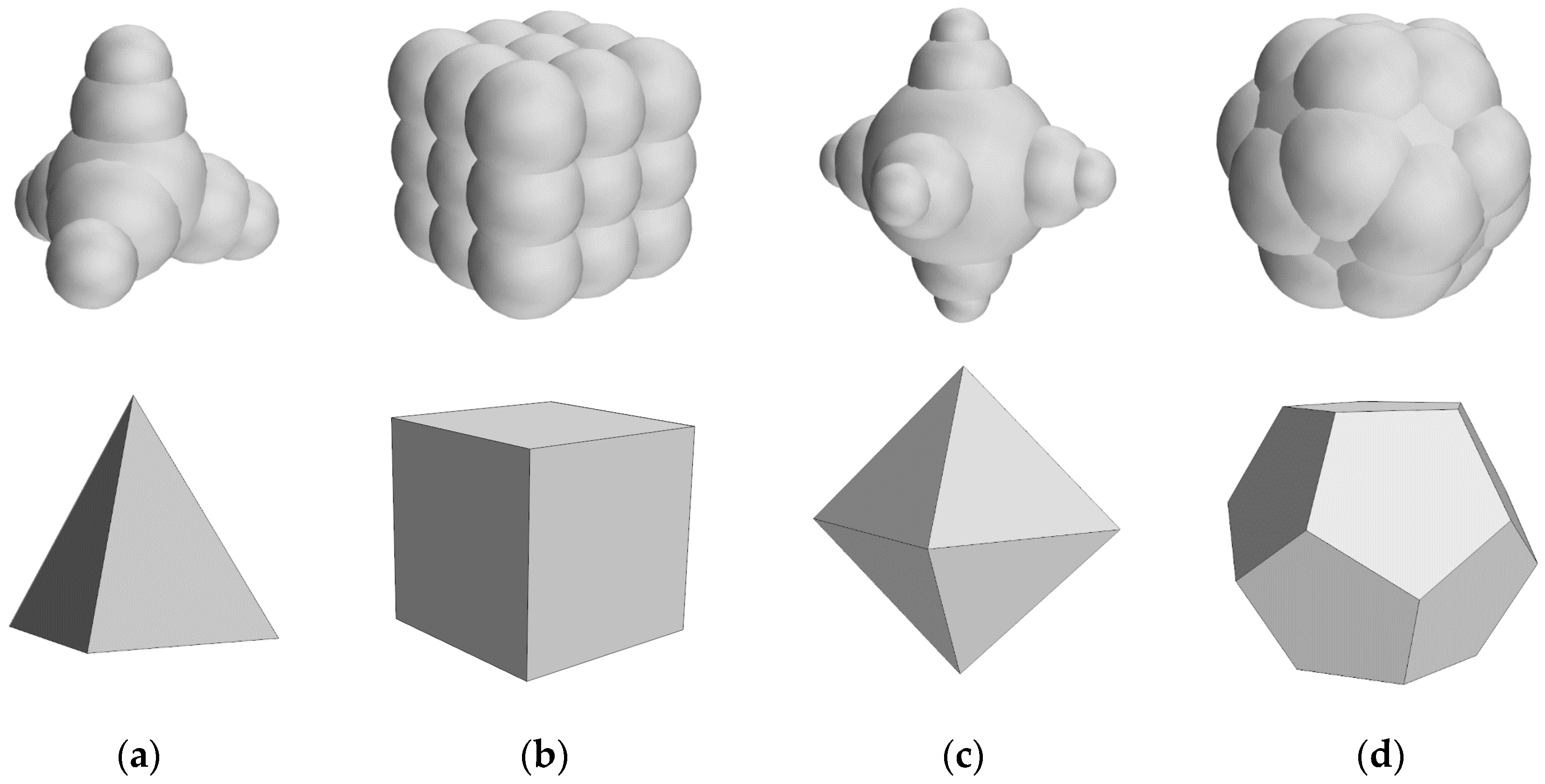
One sphere and four regular polyhedrons (see
Figure 2a–d, respectively), namely the tetrahedron, hexahedron, octahedron, and dodecahedron, were mainly modeled to represent different-shaped particles in this study. The polyhedron particles were approximated by fixing a number of spheres together, which can overlap with each other. In addition, these spheres could hold various sizes and do not separate during contacts. The properties of composited polyhedron particles are listed in
Table 2, where
ξ denotes the particle sphericity,
De denotes the equivalent spherical diameter, and
ρp denotes the particle density. Sphericity is the most commonly used measure accounting for the shape of a non-spherical particle. It can be defined as:
where
Ss and
Sp, respectively, denote the superficial areas of a sphere and a non-spherical particle. Furthermore, the volume concentration of these particles above is set as 2%, and particles are produced in the vicinity of the pump inlet with arbitrary positions and orientations. The Hertz-Mindlin contact model [
13] and a soft-sphere model [
14] are applied to model the collisional forces of a particle with other particles or wall boundaries in DEM.
Table 3 summarizes the coefficients of interactions included in the applied models. Moreover, the abrasive wear in this work is modeled using the Archard wear model [
15], while the erosive wear is modeled using the Oka wear model [
16,
17], which has been widely adopted.
2.4. Liquid Phase Setup
In this work, one major consideration in the CFD-DEM coupling method is the calculation time-cost to obtain an unsteady flow field within the entire pump. In addition, the realizable k-ε model has strengths in rotating and boundary-free shear flows with considerable computational efficiency and stability [
18]. Therefore, the transient Reynolds averaged Navier-Stokes (RANS) equation with the realized two-layer k-ε turbulence model was solved, according to the SIMPLEC algorithm in STAR-CCM+ software. The liquid was defined as incompressible water, and the dynamic viscosity and density are 8.887 × 10
−3 Pa·s and 998 kg/m
3, respectively. Moreover, the pump walls were determined as a no-slip boundary condition, and the two-Layer all y+ wall treatment was adopted as a wall function. The pump inlet was defined as a velocity inlet with a constant profile of 1.829 m/s, and the pump outlet was defined as a pressure outlet. The residual value of each variable for convergence was determined as 10
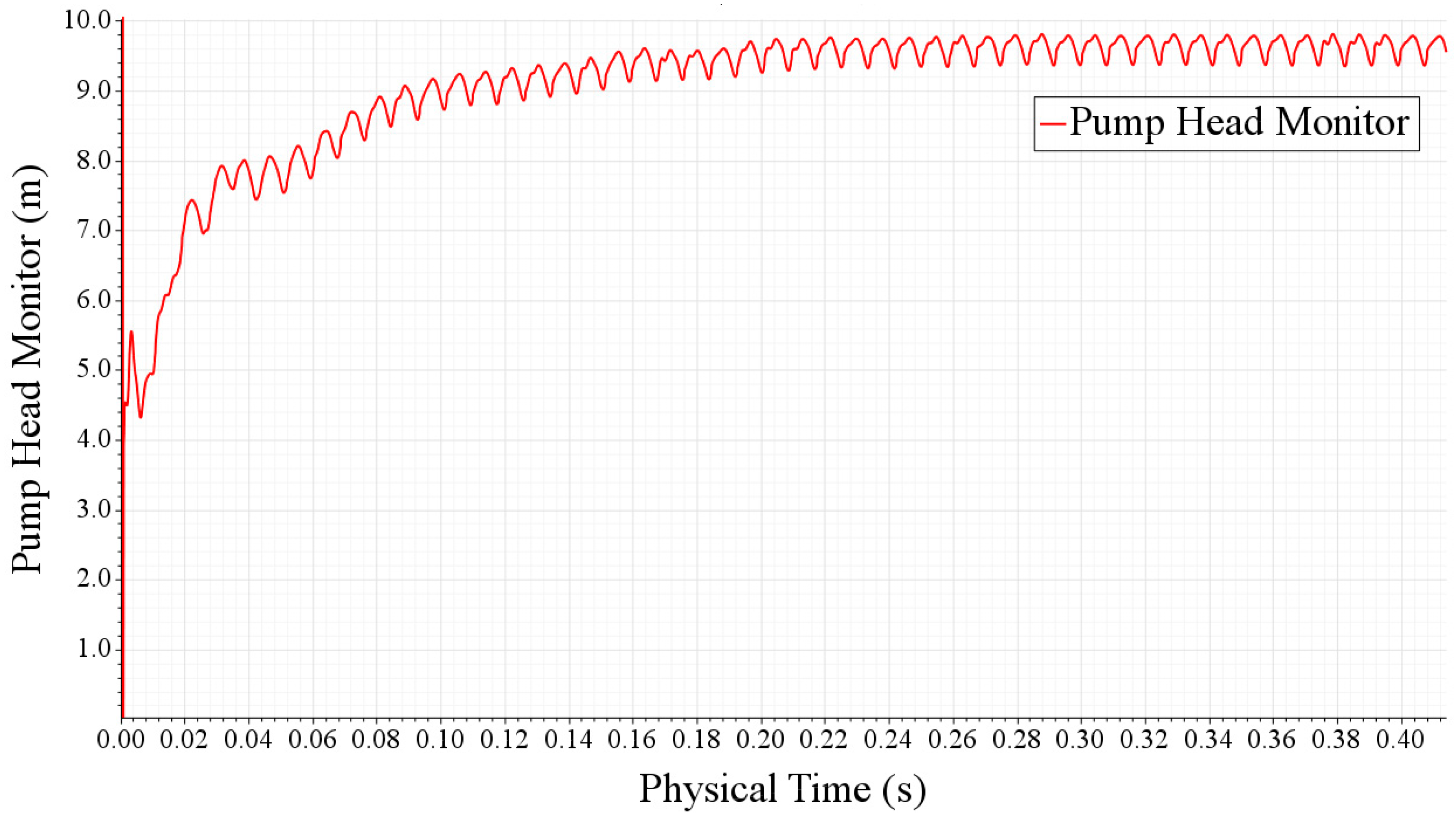
−4. In addition, the pump head fluctuations as a function of physical time were monitored in
Figure 3. It is apparent that pump head fluctuations achieve stability with a regular vibration at about
t = 0.24 s, which indicates a spatial convergence.
3. Results
3.1. Validation
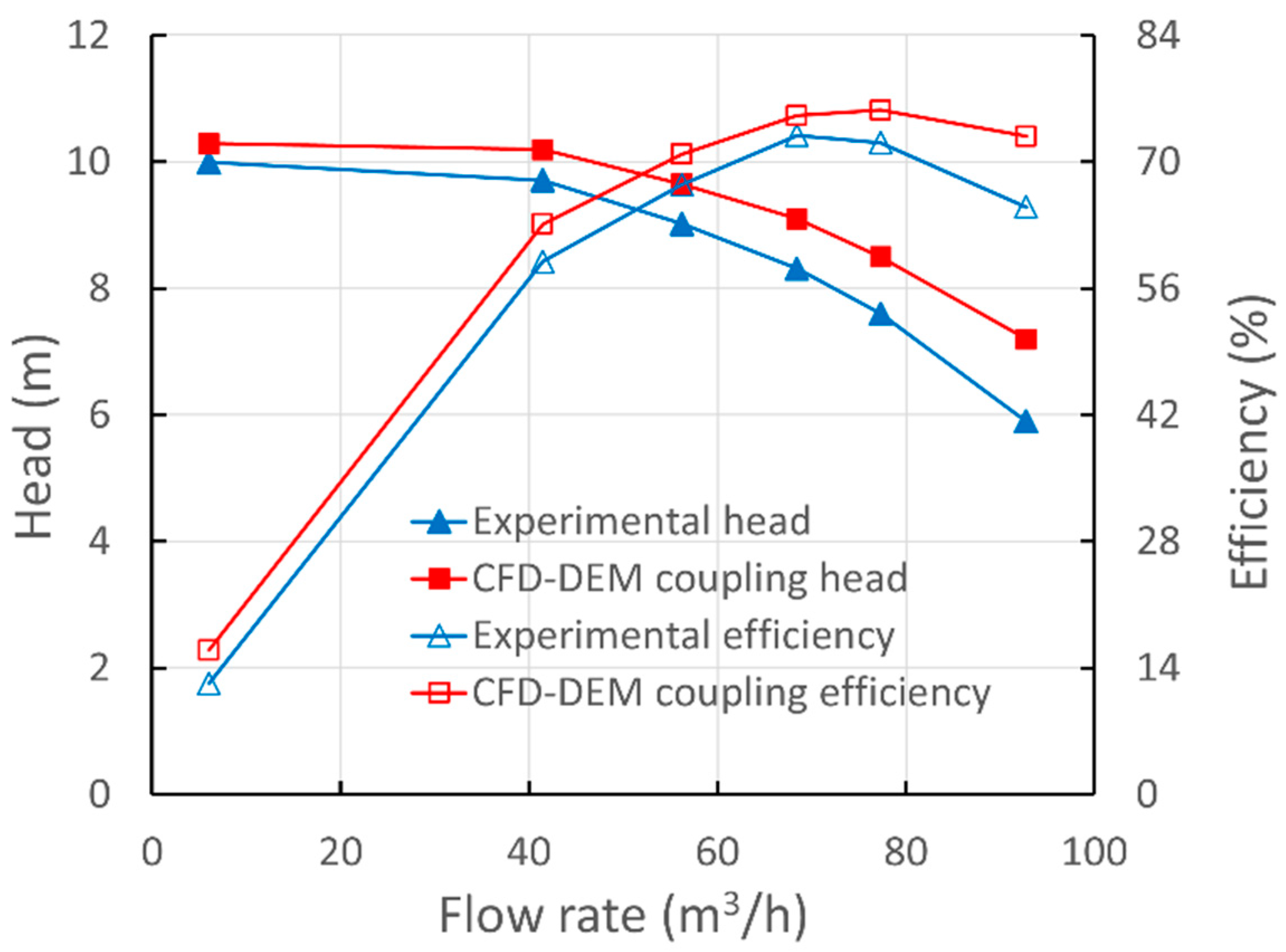
As shown in
Figure 4, in order to validate the CFD-DEM coupling, the numerical head and efficiency of the centrifugal pump as a function of liquid flow rate were compared with the experimental data from one of the pump companies in China [
19]. The computational pump model kept the same parameters as that tested in the experiment. Overall, the numerical curves follow the tendency of experimental results with acceptable accuracy, which indicates the feasibility of the CFD-DEM coupling method. Moreover, the CFD-DEM coupling data are slightly greater than the experimental ones for all flow conditions. This discrepancy could be due to the neglect of mechanical and volume losses caused by bearings and seals in the simulation.
3.2. Particle Distribution
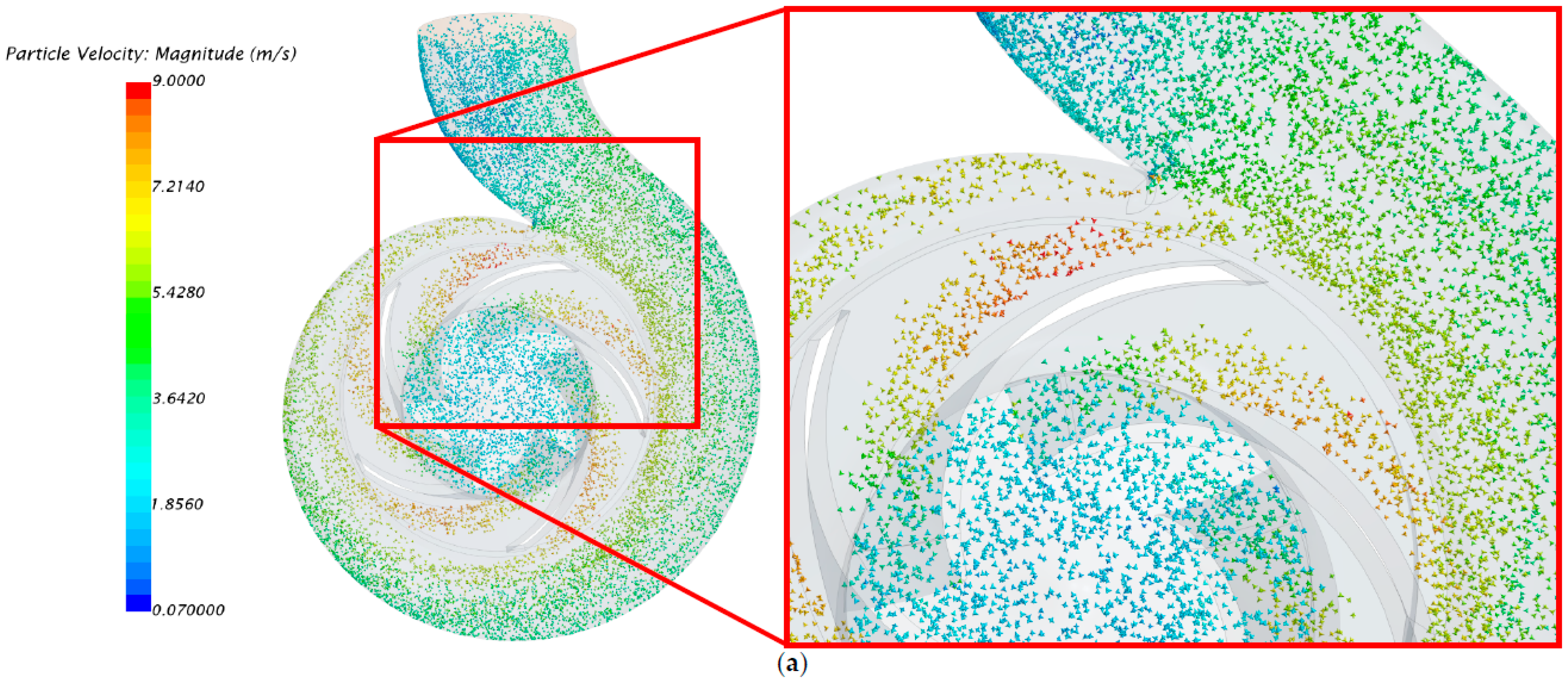
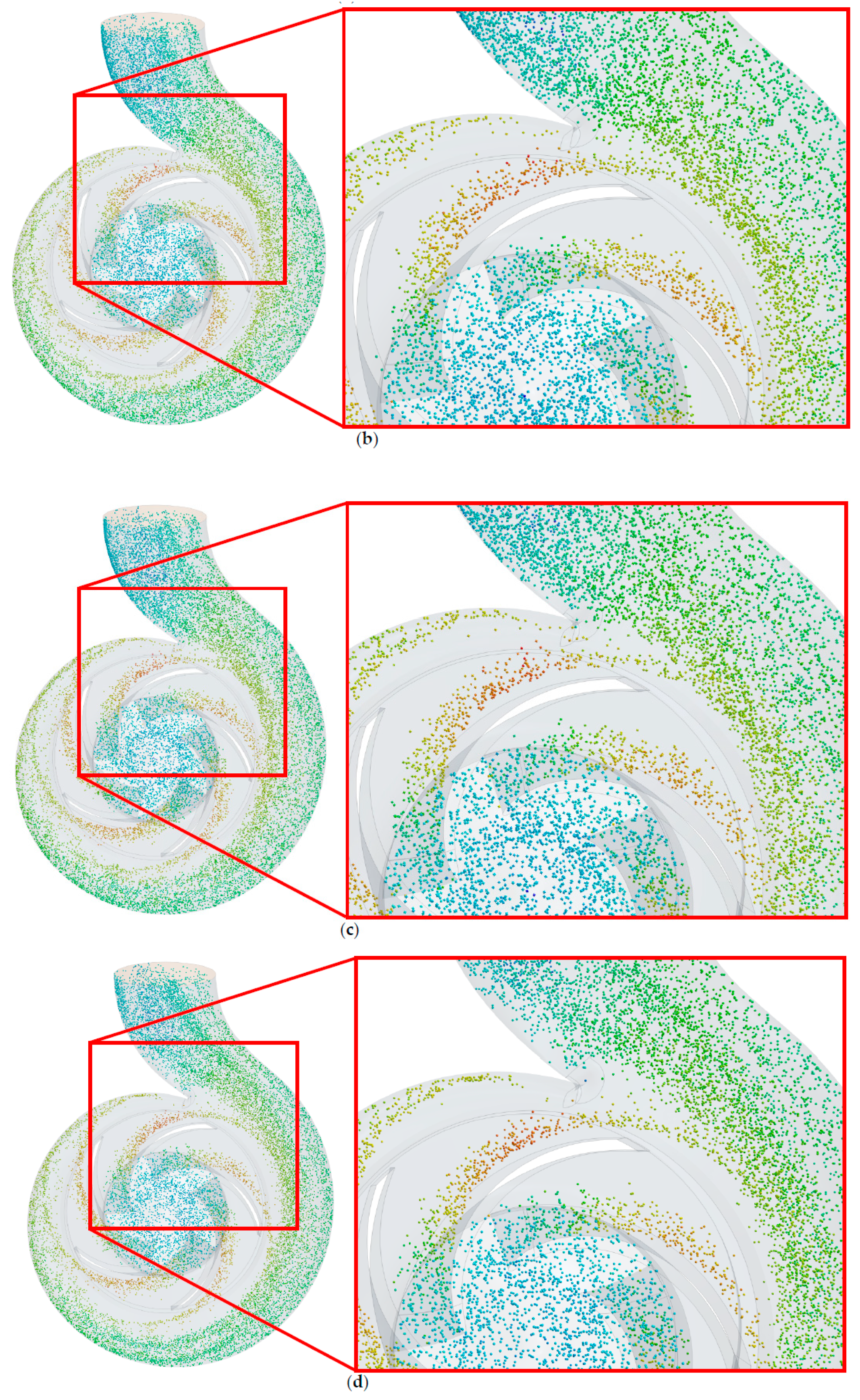
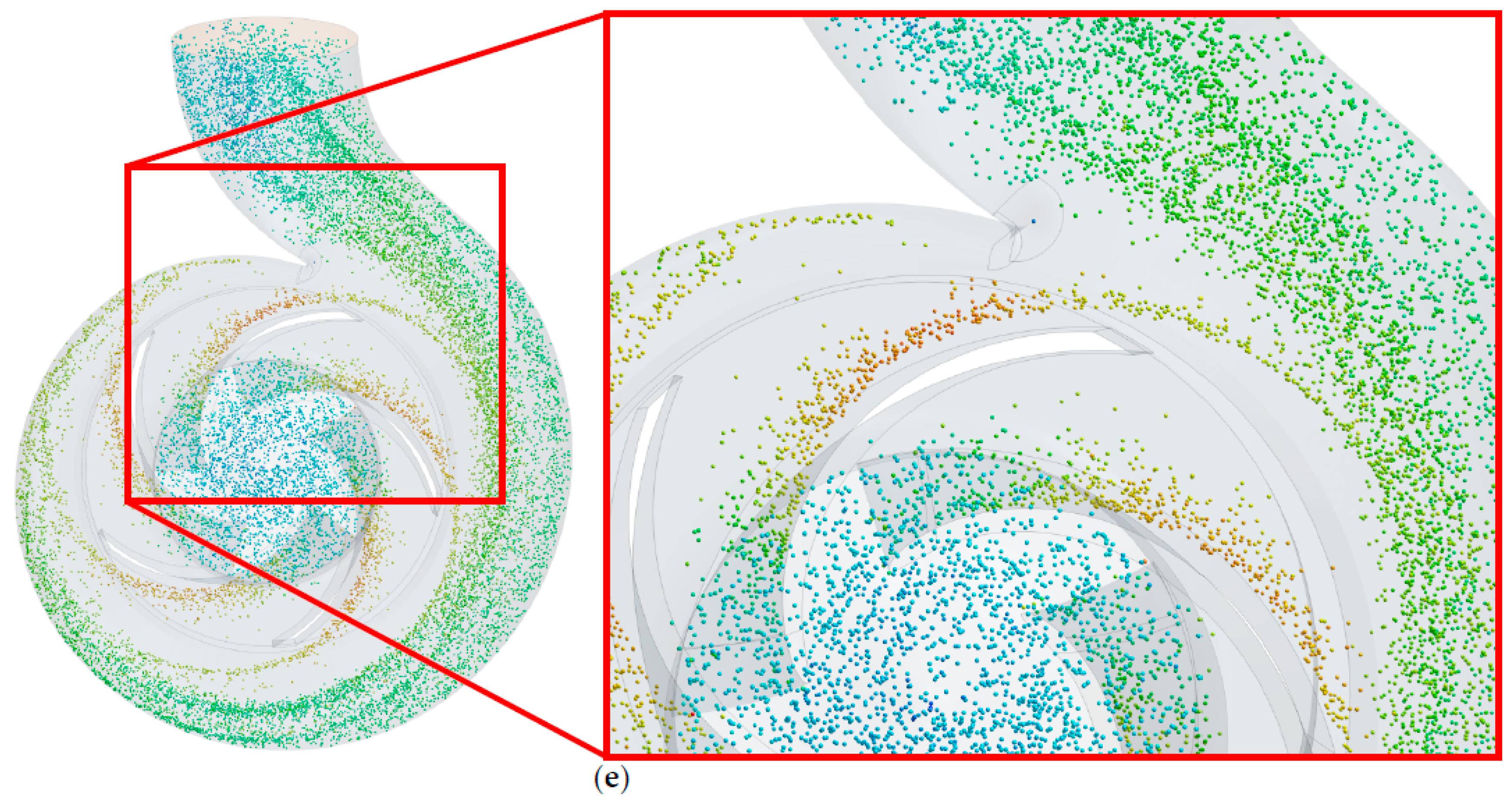
Figure 5 shows the trajectory and distribution of four regular polyhedron and spherical particles with the same equivalent diameter under the design flow rate. For a better view of particle distribution inside the impeller and volute, the inlet pipe is hidden in the current vision. Generally, most particles have a tendency to sustain a stable spiral trajectory following the volute. Moreover, particle trajectories basically correspond to the profile of the impeller blade. In the volute, most particles move along the wall surface and flow downstream to the pump outlet. In addition, particle concentrations are non-uniform within the impeller passage, with concentrations higher near the impeller inlet section and the blade pressure side.
However, there are a number of interesting differences in the distribution among different-shaped particles. Particles with low sphericity (see
Figure 5a,b) are evenly distributed in the vicinity of each blade pressure side and volute wall. By contrast, with higher sphericity, particles tend to cluster in specific areas (see
Figure 5c–e). One prominent feature is that the white spaces shown in the image within the volute are becoming apparent. Another feature is that more particles move closer to the blade pressure side (compare
Figure 5a,e). Since the major changing factor is the shape of particles, an implication of these results is the possibility that the various drag fore and collision behavior of different-shaped particles may affect their trajectory and distribution in a centrifugal pump. Moreover, these results are associated with some wear results in the following discussion.
3.3. Wear of Flow Parts
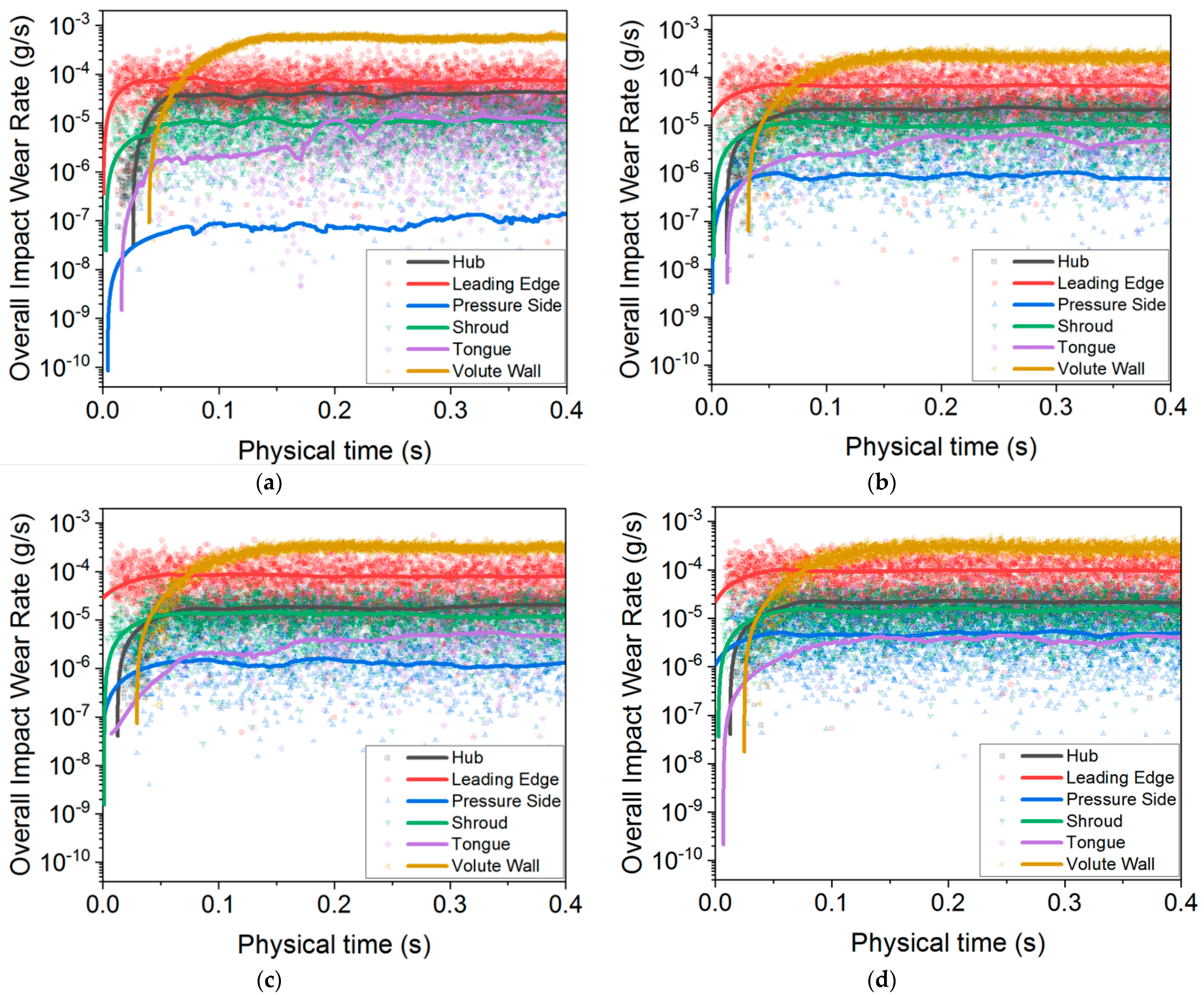
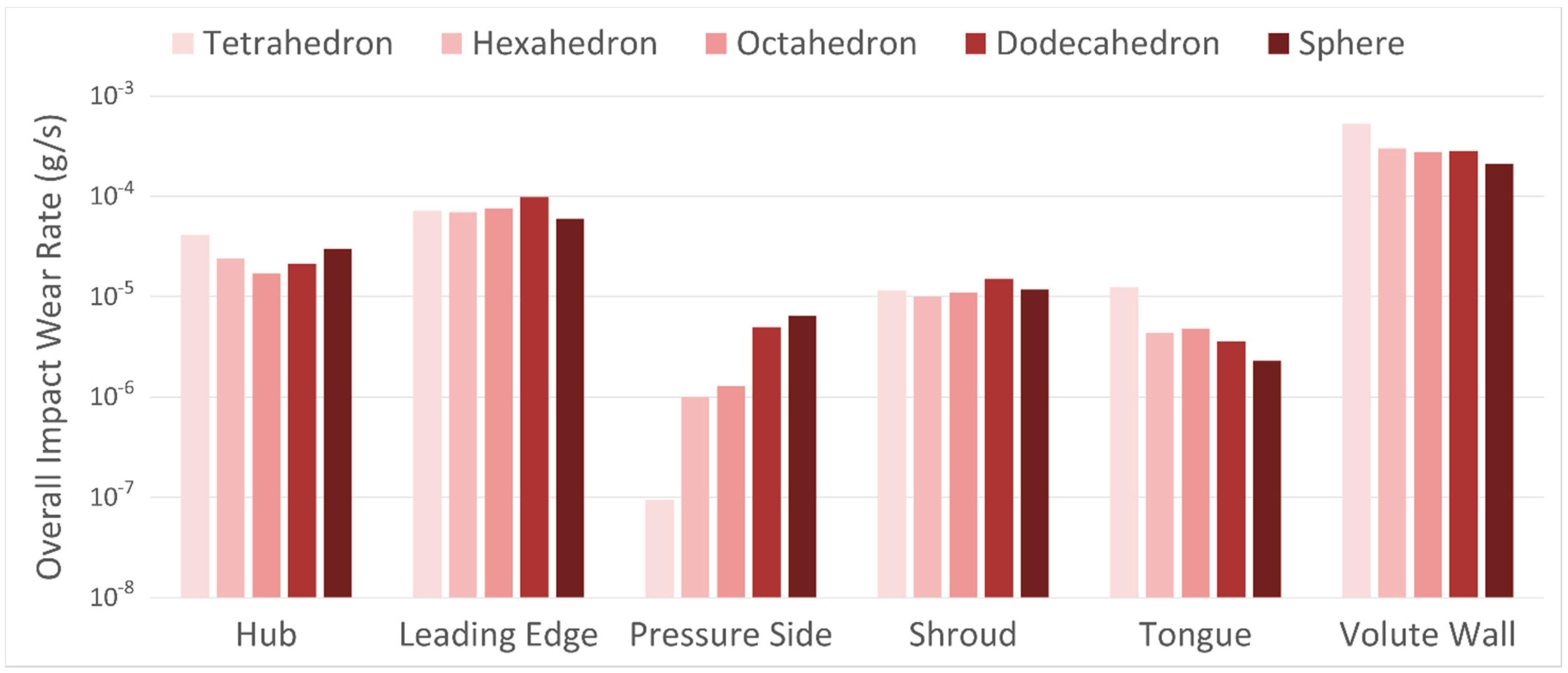
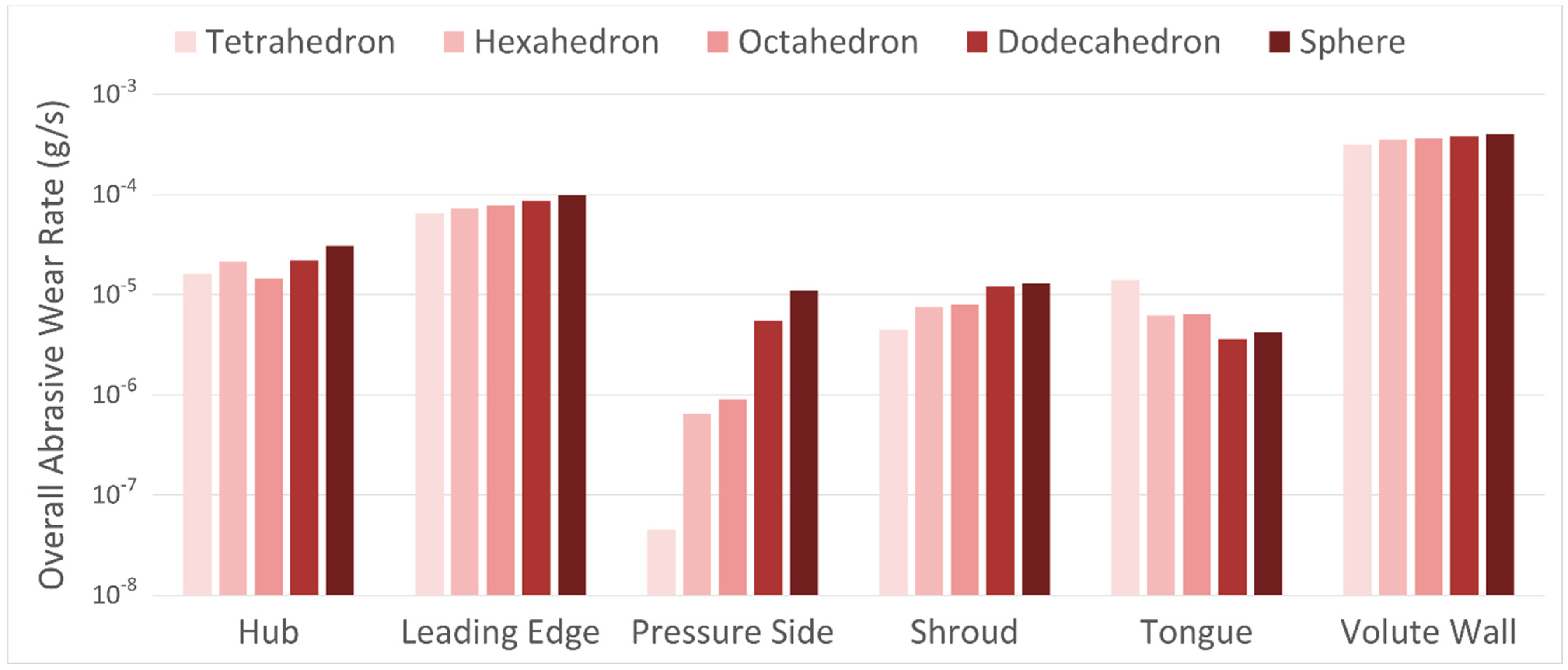
For investigating the influence of particle shape on the wear characteristics in the centrifugal pump, the overall impact wear and abrasive wear rate of each flow part are monitored through time, as shown in
Figure 6 and
Figure 7, respectively. Only the wear data on the hub, shroud, leading edge of the blade, pressure side of the blade, tongue, and volute have been detected. This means no wear erosion or the wear rate less than computational accuracy exists on the suction side of the blade and trailing edge of the blade. The most likely cause of no wear data there could be a relatively small particle flow rate.
It can be seen from the data in
Figure 6 that the uncertainty of scattered data points from different flow parts varies significantly. In general, the overall impact wear rate of the hub has experienced minimal fluctuations for all particle conditions. A possible explanation for this might be that volute is a stationary part and has the largest surface area. However, the time-averaged data curves of all flow parts have achieved acceptable stability within computation time, indicating the convergence and subsequent wear analysis. Moreover, it can be found that the order of impact wear rate on the volute wall, leading edge, and hub remains the same for all particle conditions. On the other hand, the order of impact wear rate on the shroud, pressure side, and tongue varies with the particle shape. Furthermore, the same chronological order of curve starting points indicates the trajectory of particles colliding with flow parts. These results of impact wear rate are similar to those of abrasive wear rate shown in
Figure 7.
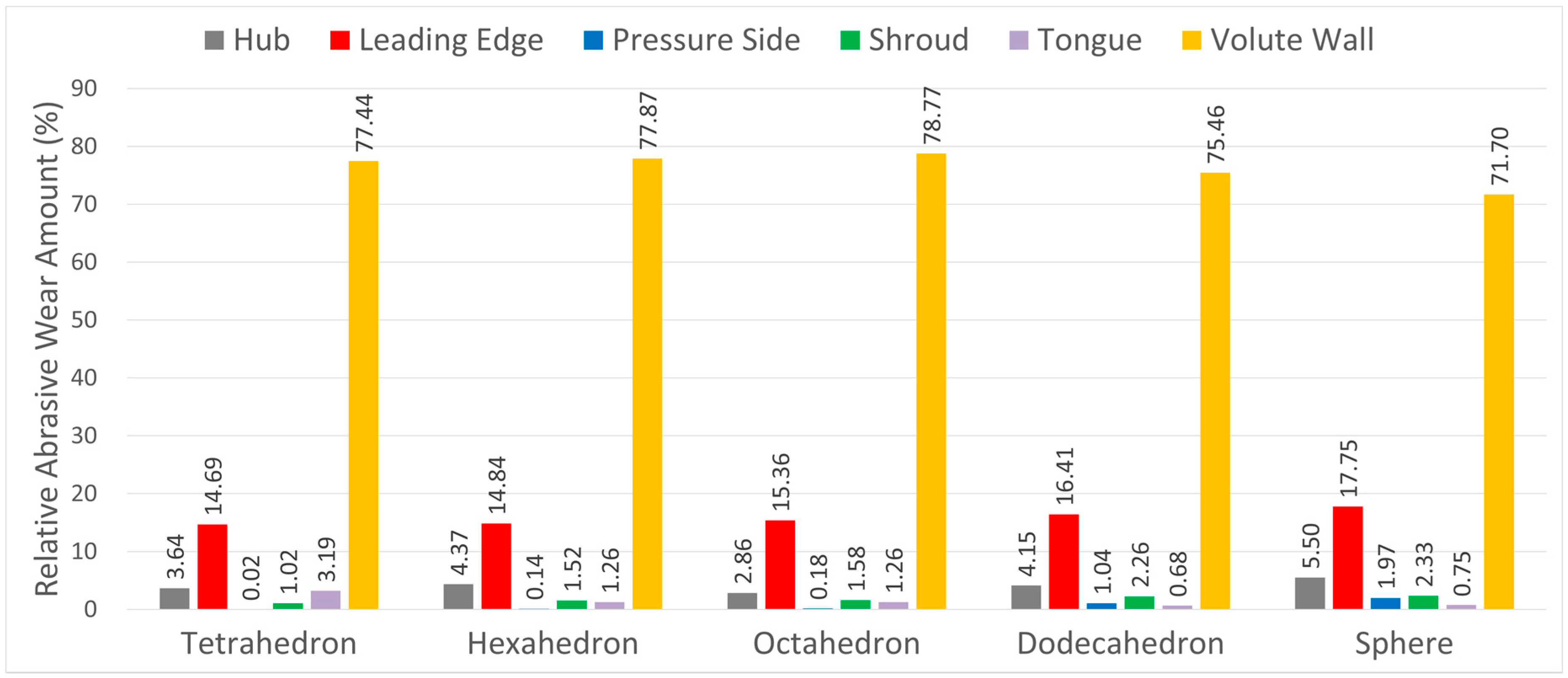
Based on the above overall wear rate results, the relative impact, and abrasive wear amounts, a ratio of each part’s wear rate to the overall pump impact wear rate, are presented for different practice conditions in
Figure 8 and
Figure 9. What stands out in
Figure 8 is that the impact wear amount of volute accounts for more than 65% of the overall pump impact wear amount per unit of time, which is generally consistent with the numerical results by Huang et al. [
6]. Likewise, the abrasive wear amount of volute accounts for more than 71%. This finding suggests that no matter what the particles and wear model is, the volute suffers the principal wear erosion.
Both in
Figure 8 and
Figure 9, it can be concluded that the wear in the impeller occurs mostly on the blade’s leading edge and hub, which are consistent with the results of numerical simulation and paint wear test conducted by Ahmad et al. [
3]. Moreover, the wear amount of the blade’s leading edge is significantly larger than that of the blade pressure side. This result could be attributed to the narrow cross-sectional area of the impeller passage near the blade leading edge, which would cause the relatively high-particle number density and further lead to another collision here. Another possible explanation for this is that most particles tend to bounce toward the impeller passage after colliding with the leading edge and do not collide with the blade pressure side anymore. Similarly, the wear amount of the hub is considerably greater than that of the shroud. This result may be due to the larger inertia of particles, causing particle trajectory biased toward the hub instead of following the flow streamline.
Figure 10 and
Figure 11 quantitatively compare the overall impact and abrasive wear rate between different flow parts. In
Figure 10, there is an evident climb in the impact wear rate of the pressure side as the particle sphericity increases (from the tetrahedron particle to the sphere particle). In the same way, the abrasive wear rate of the pressure side has experienced a dramatic rise with particle sphericity increasing in
Figure 11. These similar trends are likely to be related to the results in
Figure 5. An increasing number of particles move closer to the blade pressure side as particle sphericity rises, which results in a growing particle collision with the pressure side.
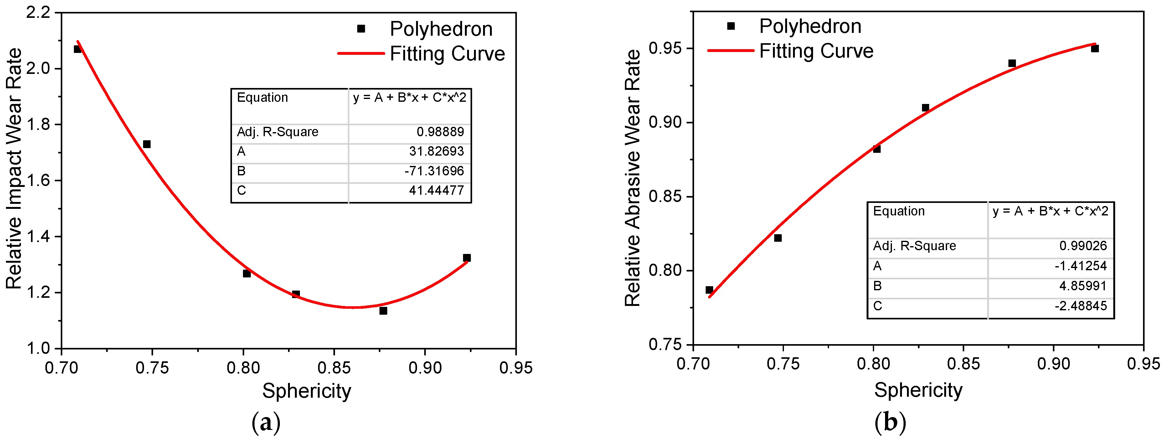
3.4. Effect of Particle Shape
The relative wear rate is defined as the pump’s overall wear rate for polyhedron particles to the pump’s overall impact wear rate for the spherical particle. Based on the numerical results of four regular polyhedron and another two polyhedron particles, the regression equations of relative impact wear rate and abrasive wear rate for the particle sphericity are modeled in
Figure 12. The fitting parameters of the parabolic function are listed in the graphs. As can be seen from the first curve (see
Figure 12a), the impact wear rate decreases first and then increases. There is a clear lowest impact wear rate when the sphericity is approximately equal to 0.86. This result may be because the impact wear is mainly affected by the impact velocity, impact angle, and other factors, not just particle sphericity. By contrast, the abrasive wear is principally subject to the particle rolling motion along the surface wall. Therefore, the relative abrasive wear rate grows steadily with increasing sphericity, as shown in
Figure 12b. These findings could benefit the pump design by predicting the wear under multi-shaped particles.
4. Conclusions
In this work, the CFD-DEM coupling method was employed to study the abrasive wear and impact wear of centrifugal pump flow parts for different-shaped particle conditions. The distribution and motion features of five different-shaped particles were compared. Two different wear models were adopted to quantitatively and qualitatively analyze the wear characteristics. The effect of particle shape on two types of wear rate was summarised in the regression equations. From the results, the following conclusions could be made as follows.
(1) All different-shaped particles have a tendency to sustain a stable spiral trajectory following the volute. Those particle trajectories basically correspond with the profile of the impeller blade. Most particles move along the wall surface and flow downstream to the pump outlet within the volute.
(2) Particles with low sphericity are evenly distributed in the vicinity of each blade pressure side and volute wall. However, particles tend to cluster in specific areas within the volute as sphericity rises. On the other hand, more particles move closer to the blade pressure side in the impeller passage with increasing sphericity.
(3) No matter what shapes the particles and wear model are, the volute suffers the principal wear erosion. Both the impact and abrasive wear in the impeller mostly occur on the blade’s leading edge. The wear amount of the hub is considerably greater than that of the shroud, likely due to the larger inertia of particles. Therefore, the flow parts mentioned above could be manufactured with more wear-resistance material than other parts.
(4) As the particle sphericity rises, there is a significant increase in the impact and abrasive wear on the pressure side due to particle trajectories biased toward the blade pressure side.
(5) The pump’s overall impact wear rate decreases first and then increases with particle sphericity rising. By contrast, the pump’s overall abrasive wear rate grows steadily with increasing sphericity.
(6) This study was limited to the effect of multi-shaped particles on abrasive and impact wear. Therefore, it would be desirable to study the influence of the particle concentration, particle size, inlet velocity, and properties of conveying fluid on the resulting wear in further study. In addition, although this paper explored the relationship between wear and particle shape, the geometries of particles were limited to correct unified shapes. Given this, some mixed and asymmetrical shapes would be considered in further studies.
Author Contributions
Conceptualization, C.T. and Y.-J.K. Methodology, C.T. and Y.-J.K. Software, C.T. and P.-Z.L. Validation, C.T. and Y.-C.Y. Formal analysis, C.T. Investigation, C.T. Resources, C.T. and Y.-C.Y. Data curation, C.T. Writing—original draft preparation, C.T. and Y.-J.K. Writing—review and editing, C.T. and Y.-J.K. Supervision, Y.-J.K. All the authors have read and agreed to the published version of the manuscript. All authors have read and agreed to the published version of the manuscript.
Funding
This work was supported by the Korea Agency for Infrastructure Technology Advancement (KAIA) grant funded by the Ministry of Land, Infrastructure, and Transport (Grant 21CTAP-C157760-02).
Conflicts of Interest
The authors declare no conflict of interest.
References
- Finnie, I. Erosion of surfaces by solid particles. Wear 1960, 3, 87–103. [Google Scholar] [CrossRef]
- Tao, Y.; Yuan, S.; Zhang, J.; Zhang, F.; Tao, J. Numerical simulation and test on impeller wear of slurry pump. Trans. Chin. Soc. Agric. Eng. 2014, 30, 63–69. [Google Scholar]
- Ahmad, K.; Baker, R.; Goulas, A. Computation and experimental results of wear in a slurry pump impeller. Proc. Inst. Mech. Eng. Part C J. Mech. Eng. Sci. 1986, 200, 439–445. [Google Scholar] [CrossRef]
- Lei, H.M.; Xiao, Y.X.; Chen, F.N.; Ahn, S.H.; Wang, Z.W.; Gui, Z.H.; Luo, Y.Y.; Zhao, X.R. Numerical simulation of solid-liquid two-phase flow in a centrifugal pump with different wear blades degree. In Proceedings of the IOP Conference Series: Earth and Environmental Science; IOP Publishing: England, UK, 2018; Volume 163, p. 012027. [Google Scholar]
- Noon, A.A.; Kim, M.-H. Erosion wear on centrifugal pump casing due to slurry flow. Wear 2016, 364, 103–111. [Google Scholar] [CrossRef]
- Huang, S.; Huang, J.; Guo, J.; Mo, Y. Study on Wear Properties of the Flow Parts in a Centrifugal Pump Based on EDEM–Fluent Coupling. Processes 2019, 7, 431. [Google Scholar] [CrossRef]
- Zeng, D.; Zhang, E.; Ding, Y.; Yi, Y.; Xian, Q.; Yao, G.; Zhu, H.; Shi, T. Investigation of erosion behaviors of sulfur-particle-laden gas flow in an elbow via a CFD-DEM coupling method. Powder Technol. 2018, 329, 115–128. [Google Scholar] [CrossRef]
- Tsuji, Y.; Kawaguchi, T.; Tanaka, T. Discrete particle simulation of two-dimensional fluidized bed. Powder Technol. 1993, 77, 79–87. [Google Scholar] [CrossRef]
- Kafui, K.; Thornton, C.; Adams, M. Discrete particle-continuum fluid modelling of gas–solid fluidised beds. Chem. Eng. Sci. 2002, 57, 2395–2410. [Google Scholar] [CrossRef]
- Cleary, P.W.; Sawley, M.L. DEM modelling of industrial granular flows: 3D case studies and the effect of particle shape on hopper discharge. Appl. Math. Model. 2002, 26, 89–111. [Google Scholar] [CrossRef]
- Santamarina, J.; Cho, G.-C. Soil behaviour: The role of particle shape. In Advances in Geotechnical Engineering: The Skempton Conference. In Proceedings of the Three Day Conference on Advances in Geotechnical Engineering, Organised by the Institution of Civil Engineers and Held at the Royal Geographical Society, London, UK, 29–31 March 2004; Advances in Geotechnical Engineering: London, UK; pp. 604–617.
- Pena, A.; Garcia-Rojo, R.; Herrmann, H.J. Influence of particle shape on sheared dense granular media. Granul. Matter 2007, 9, 279–291. [Google Scholar] [CrossRef]
- Mindlin, R.D. Compliance of elastic bodies in contact. J. Appl. Mech. ASME 1949, 16, 259–268. [Google Scholar] [CrossRef]
- Hertz, H. Über die Berührung fester elastischer Körper. J. Für Die Reine Und Angew. Math. 1882, 92, 22. [Google Scholar]
- Archard, J. Contact and rubbing of flat surfaces. J. Appl. Phys. 1953, 24, 981–988. [Google Scholar] [CrossRef]
- Oka, Y.I.; Okamura, K.; Yoshida, T. Practical estimation of erosion damage caused by solid particle impact: Part 1: Effects of impact parameters on a predictive equation. Wear 2005, 259, 95–101. [Google Scholar] [CrossRef]
- Oka, Y.; Yoshida, T. Practical estimation of erosion damage caused by solid particle impact: Part 2: Mechanical properties of materials directly associated with erosion damage. Wear 2005, 259, 102–109. [Google Scholar] [CrossRef]
- Shih, T.H.; Liou, W.W.; Shabbir, A.; Yang, Z.; Zhu, J. A new k-ϵ eddy viscosity model for high reynolds number turbulent flows. Comput. Fluids 1995, 24, 227–238. [Google Scholar] [CrossRef]
- Yu, D.H.; Chen, Y.; Wang, C.; Bai, X.B.; Yang, Y.C. Simulation and experimental study on external performance of the volute centrifugal pumps. China Rural Water Hydropower 2020, 1, 181–187. [Google Scholar]
Figure 1.
(a) Geometric model. (b) Polyhedron meshes and prism layers.
Figure 1.
(a) Geometric model. (b) Polyhedron meshes and prism layers.
Figure 2.
Particle DEM and geometrical models: (a) tetrahedron, (b) hexahedron, (c) octahedron, (d) dodecahedron.
Figure 2.
Particle DEM and geometrical models: (a) tetrahedron, (b) hexahedron, (c) octahedron, (d) dodecahedron.
Figure 3.
Variations in pump head for the sphere particle condition.
Figure 3.
Variations in pump head for the sphere particle condition.
Figure 4.
Comparison of the pump head and efficiency between the simulation and experimental data.
Figure 4.
Comparison of the pump head and efficiency between the simulation and experimental data.
Figure 5.
Trajectory and distribution of different particles: (a) tetrahedron, (b) hexahedron, (c) octahedron, (d) dodecahedron, and (e) sphere.
Figure 5.
Trajectory and distribution of different particles: (a) tetrahedron, (b) hexahedron, (c) octahedron, (d) dodecahedron, and (e) sphere.
Figure 6.
Overall impact wear rate of flow parts as a function of time: (a) tetrahedron, (b) hexahedron, (c) octahedron, (d) dodecahedron, and (e) sphere.
Figure 6.
Overall impact wear rate of flow parts as a function of time: (a) tetrahedron, (b) hexahedron, (c) octahedron, (d) dodecahedron, and (e) sphere.
Figure 7.
Overall abrasive wear rate of flow parts as a function of time: (a) tetrahedron, (b) hexahedron, (c) octahedron, (d) dodecahedron, and (e) sphere.
Figure 7.
Overall abrasive wear rate of flow parts as a function of time: (a) tetrahedron, (b) hexahedron, (c) octahedron, (d) dodecahedron, and (e) sphere.
Figure 8.
Relative impact wear amount of flow parts.
Figure 8.
Relative impact wear amount of flow parts.
Figure 9.
Relative abrasive wear amount of flow parts.
Figure 9.
Relative abrasive wear amount of flow parts.
Figure 10.
Overall impact wear rate of flow parts.
Figure 10.
Overall impact wear rate of flow parts.
Figure 11.
Overall abrasive wear rate of flow parts.
Figure 11.
Overall abrasive wear rate of flow parts.
Figure 12.
Regression equation for particle sphericity: (a) relative impact wear rate and (b) relative abrasive wear rate.
Figure 12.
Regression equation for particle sphericity: (a) relative impact wear rate and (b) relative abrasive wear rate.
Table 1.
Mesh independence analysis.
Table 1.
Mesh independence analysis.
| Mesh Number | Pump Head (m) | Deviation (%) |
|---|
| 650,584 | 8.47 | |
| 833,197 | 8.79 | 3.83 |
| 1,042,510 | 8.87 | 0.92 |
| 1,255,663 | 8.89 | 0.23 |
| 1,349,142 | 8.90 | 0.15 |
Table 2.
Particle configurations.
Table 2.
Particle configurations.
| | Tetrahedron | Hexahedron | Octahedron | Dodecahedron | Sphere |
|---|
| ξ | 0.709 | 0.802 | 0.829 | 0.923 | 1 |
| De (mm) | 1 | 1 | 1 | 1 | 1 |
| ρp (kg/m3) | 2600 | 2600 | 2600 | 2600 | 2600 |
Table 3.
Collison configurations.
Table 3.
Collison configurations.
| Collision Coefficient | Particle-Particle | Particle-Wall |
|---|
| Restitution | 0.5 | 0.7 |
| Static friction | 0.3 | 0.15 |
| Rolling friction | 0.01 | 0.01 |
| Publisher’s Note: MDPI stays neutral with regard to jurisdictional claims in published maps and institutional affiliations. |
© 2021 by the authors. Licensee MDPI, Basel, Switzerland. This article is an open access article distributed under the terms and conditions of the Creative Commons Attribution (CC BY) license (https://creativecommons.org/licenses/by/4.0/).


