1. Introduction
For the purpose of reducing the use ratio of fossil fuels, nuclear energy, etc., due to environmental pollution and the consequent risks of the use of this kind of energy, research on eco-friendly energy technologies, which use energy existing in nature, is carried out. Recently, among eco-friendly energies, the demand for power-generation systems using solar light, which is a renewable energy, is increasing. Additionally, research for the purpose of increasing the power generation efficiency of, and reducing the costs of, solar energy is being carried out continuously because solar energy has the advantage that it can supply us with inexhaustible clean energy from the sun. At present, in the cases of public buildings and buildings with large sites, the installation of, and investment in, renewable energy facilities, including photovoltaic facilities, are obligatorily enforced. The aim is to increase the number of solar power and wind power facilities by 2025 to more than three times the 12.7 GW achieved in 2019. In addition, due to the increase in leisure industries such as camping, equipment, including photovoltaic generators for camping cars, is being mass-produced which enables energy accumulated in a battery at night to be used together with a battery. However, photovoltaic power generation has the disadvantage that the output is unstable, not constant and not continuous, because it is highly dependent on the atmospheric condition, surrounding structures, etc., and there is a temporal limit as power generation is only possible during daylight hours.
The method of following the maximum power point, or following a maximum power point which changes every moment according to the variable output of solar light, is called the maximum power point tracking (MPPT) algorithm [
1]. In power generation by the use of eco-friendly energy, constant current and voltage are required for lead–acid and lithium batteries at the time of energy storage device (ESS) charge. In the case of solar light, the amount of photovoltaic power generated is highly variable depending on sunrise, sunset, clouds, leaves, weather, etc., so a situation occurs where the output of more than a certain amount of power is not possible, and because the maximum power point in the low-illumination section cannot be transmitted to an energy storage device, the efficiency of the power transmission is lowered.
At present, various studies into the performance and efficiency of energy storage, including photovoltaic power generation, are being conducted. The method using MPPT is the most actively discussed subject [
2,
3,
4]. There is also an electro-optical tracking method which determines the reference position of a panel by use of devices such as current, voltage, and feedback sensors. Additionally, there is a method which tracks the position of the sun by using the latitude and longitude of the location where the solar panel is installed [
5,
6]. Usage of the Digital Signal Processors (DSP)-controlled dual-MPPT method using fuzzy logic control [
7], the incremental conductance (INC) method, and the method using artificial intelligence (neural network, NN) is also increasing [
8]. Research into maximizing the power extraction from the photovoltaic generator (PVG) by use of a sliding mode controller (SMC) (which drives a boost converter between PVG and load, and the system using a supercapacitor) is also emerging [
9,
10,
11]. A study on improving the temperature characteristics of photovoltaic panels (PVs) integrated with lithium storage batteries, and a study on the chemical-method approach are also under way. There is discussion about the design of a low-cost photocatalytic oxidation reactor to maximize the conversion and storage efficiency of solar energy [
12,
13].
In this paper, we intend to present a control system which transmits power to a storage device after charging a low-power section to a supercapacitor, by use of an integral controller using a supercapacitor for energy for the low-illumination section. This also allows the power generated at the maximum power point below the reference power to be transmitted to an energy storage device, so that the power generated in low-power sections such as those affected by partial shade, cloudy weather, sunrise and sunset, etc., can be charged without being discarded.
The composition of this paper is as follows: in
Section 2, the Pulse Width Modulation (PWM) and MPPT methods used as existing solar controllers are introduced; in
Section 3, the system presented in this study is explained; in
Section 4 and
Section 5, experiments on, and results of, the system described are presented; and in
Section 6, the conclusions of this paper are presented.
2. Existing System
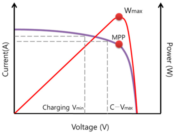
The typical power curve of the output of photovoltaic panels is shown in
Figure 1. The MPP curve corresponds to the left vertical axis and the Wmax curve corresponds to the right vertical axis. In the existing photovoltaic panels, PWM and MPPT methods are widely used to store energy. There are differences in cost and space limitations, ambient temperature, efficiency, etc., for these methods.
Basically, PWM is a method of pulse-width modulation, and MPPT is a method of maximum power point tracking. The solar controller monitors the condition of the battery and adjusts the charging speed to prevent the battery from being overcharged [
2].
2.1. PWM
The PWM method is considered as acting as a switch between the photovoltaic panels and the battery. This method adjusts the duty ratio of the switch, and lowers the duty cycle to prevent the battery from being heated and overcharged as the battery is charged fully, and it reduces the amount of solar energy being delivered into the battery. As a result, if the switch between the photovoltaic panels and the battery is closed, the voltage between the panels and the battery becomes almost equal.
As the battery charges the voltage increases, and if it approaches the full-charge state the PWM controller starts the operation to disconnect and reconnect the panels and the battery. Through this operation, the stress on the battery is reduced, so the battery life can be kept, and at the same time the battery can be maintained continuously in a full-charge state [
2].
The PWM charging controller has the advantage of being priced lower than the MPPT controller and is a low-cost solution suitable for small systems with cell temperatures between 45 °C and 75 °C. However, when charging, the PWM method adjusts the power produced in the photovoltaic panels to the charging voltage of the battery, and since most of operating position is slightly above the maximum power point, there occurs a loss in power compared to the MPPT method; this is confirmed in
Figure 1. Therefore, it is recommended to adjust the voltage of the photovoltaic panels to the charging voltage of the battery.
2.2. MPPT
The MPPT method is a more sophisticated and more expensive controller than the PWM controller. It adjusts the voltage produced in the photovoltaic panels to the charging voltage of the battery according to the maximum output point, and also changes the current to match the charging voltage. In the case of the MPPT controller, a DC–DC converter is included (based on a synchronous buck converter circuit). In the P–V power curve, there are sections in which the power increases or decreases depending on the voltage, and this method changes the voltage periodically to find the maximum power point (MPP) and compares the voltage change amount and the power change amount. In this way, the MPPT controller finds the maximum power point of the photovoltaic panels, and charges the panels in an algorithmic manner which maintains the most efficient amount of power [
2,
14].
The effect of the MPPT method is best shown when shadows are generated by clouds, buildings, trees, etc., causing the maximum power point to change intermittently. In the case of PWM, since the maximum power point is not found, the charge amount decreases due to the occurrence of shadows; however, in the case of MPPT, the maximum power point, which changes instantaneously in the given situation, is quickly found which reduces the loss of power to the utmost. MPPT has better performance at lower temperatures than PWM, and unlike PWM, where the photovoltaic panel voltage and battery voltage must be matched, in MPPT, the photovoltaic panel voltage may be higher than the battery voltage [
15].
3. Proposed System
The purpose of this experiment was to store the power in a storage device through the accumulation-type controller, by use of a supercapacitor, for the low-power output of the photovoltaic panels in the low-illumination section. We utilized a controller system that transmits the power to a storage device after accumulating the low power with the accumulation-type controller by feeding back the state of the output power of the photovoltaic panels.
In order to drive the integrator, it is necessary to know the output state of the photovoltaic panels, so a voltage sensor and a current sensor for measuring the output power were connected to Arduino, and a signal was sent to operate the relay which drives the integrator according to the PV output power as measured by the sensors.
The output power of the PV is measured using a voltage sensor and a current sensor, and if the PV output power enters the low-illumination section and drops below a certain power value, a HIGH signal is applied to the relay to drive the integrator, and turns the relay to the ON state.
If the relay operates (ON state), the output power of the PV starts to be stored in the supercapacitor, and once a certain voltage is charged in the supercapacitor, the relay changes to the OFF state and the power stored in a supercapacitor is transmitted to the battery through a flyback circuit.
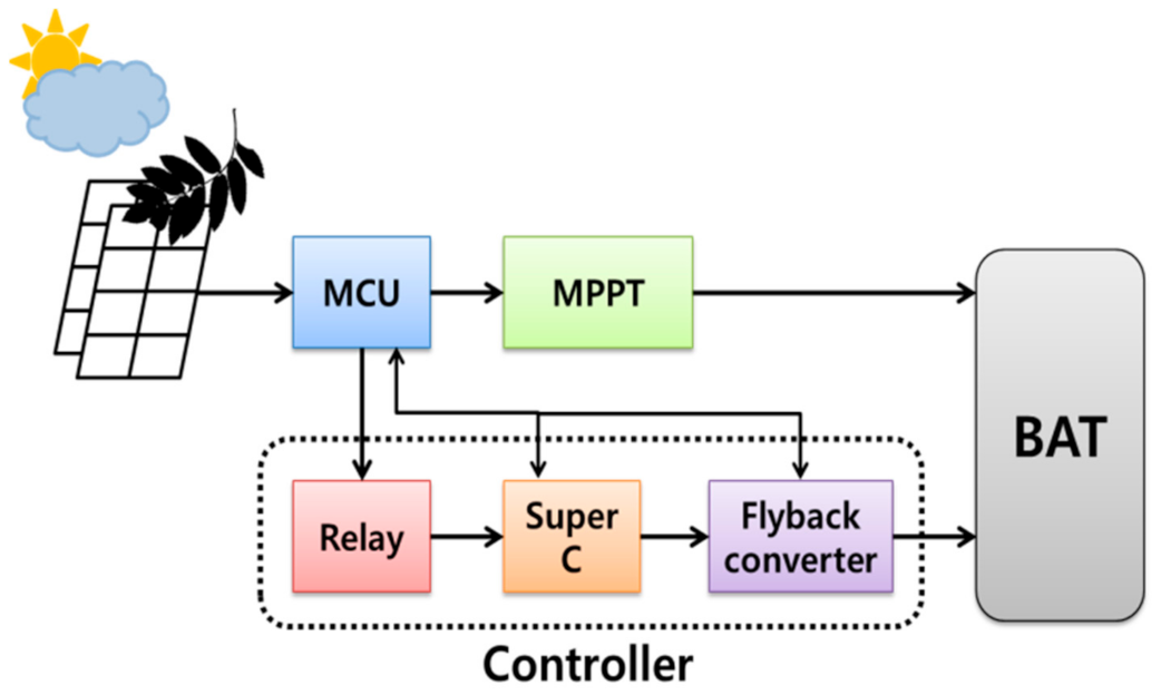
Figure 2 is a configuration of the circuit diagram for the overall operation. The whole system is largely divided into photovoltaic panels, MCU, MPPT, supercapacitor integrator, and battery.
3.1. Supercapacitor
A supercapacitor is an energy storage device (ESS) called a high-performance electricity storage device or a large-capacity storage battery, and is classified as a next-generation battery because it has a faster charge/discharge speed, a longer charge/discharge cycle life, and a higher power density than existing ion batteries. It is expected that in the future, when the development of such characteristics of the supercapacitor is completed, it will be used in parallel with the battery, or it will be able to replace the battery in various fields [
16,
17].
In the case of an electric double-layer capacitor (EDLC), unlike a battery which operates by chemical reaction, it utilizes the phenomenon of charging by use of ion movement to electrode and electrolyte interface, or a chemical reaction on the surface. That is, since there is no chemical reaction and there is no endothermic reaction, it has the characteristics of an output five times higher than that of a battery and has high power density even in low-temperature environments. It is also used as a battery replacement due to its fast charging/discharging speed, its efficiency, and its cycle life characteristics. The use of a supercapacitor improves the power quality of a power generation system of eco-friendly energy which reacts slowly to responses [
18,
19].
However, due to the limitation that electric charges are accumulated only on the electrode surface, the capacity is smaller than that of a normal battery, and if the capacity increases the volume also increases, so it is used in parallel or as an auxiliary rather than alone.
The integrator, by use of the supercapacitor proposed in this paper, is utilized as a compensation-type integrator, which performs as an energy storage buffer and enables fast charging/discharging, rather than using the supercapacitor alone as an energy storage device. Through this, energy at a low power is collected and stored in a storage device, thereby more power is harvested than the existing photovoltaic charge amount.
3.2. Boost Converter (Flyback)
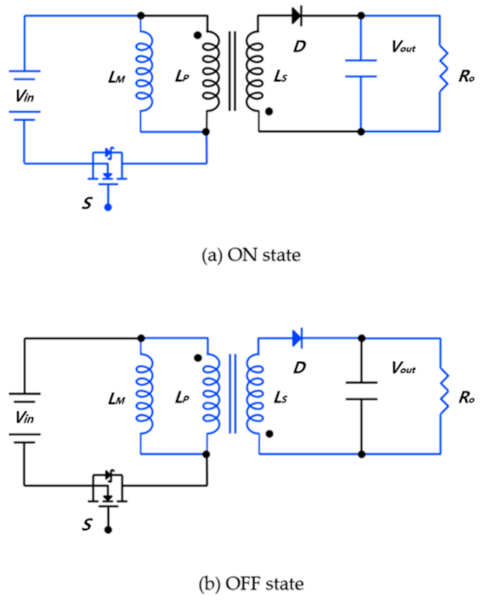
In some cases, it is necessary to separate input and output for the purpose of circuit protection. The flyback converter can be viewed as a form through which the input and output of the buck/boost converter is separated by the use of a transformer.
Figure 3 is the basic circuit of a flyback converter,
Figure 3a shows the flow of the ON state, and
Figure 3b shows the flow of the OFF state.
First, looking at
Figure 3a (ON state), when the switching device is conducted, the input voltage is applied to the inlet winding, and voltage proportional to the turn ratio (n) is applied to the outlet. However, because the polarity for the inlet winding is set in a reverse direction, no current flows through the outlet diode, so it becomes the same as the ON state. That is, the energy is stored only in the inlet.
If the switching device is in the OFF state, it shows the same flow as in
Figure 3b. The voltage applied to the inlet winding is disconnected, and at this time, a reverse electromotive force is generated by the energy stored in the inlet, and the current flows in the outlet. The outlet diode is conducted, and the accumulated energy is released through the load.
There is a discontinuous motion and a continuous motion in the flyback motion. A discontinuous motion refers to the case wherein the current of L
M becomes 0 before OFF is changed to ON, and a continuous motion refers to the case wherein the current of L
M does not become 0 before OFF is changed to ON [
20].
In the system proposed in this paper, the design of the boost converter (flyback) circuit is based on the LT1619ES8 device. If the power is supplied from a supercapacitor, the output voltage of LT1619ES8, that is, the voltage input to the battery, is set through a resistor divider as shown in Equation (1), and is currently set to 16 V.
3.3. System Modeling
3.3.1. Integrator
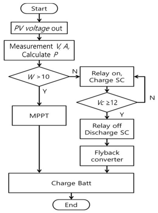
The presence or absence of the integrator operation is determined by the output power of the photovoltaic panels. The output power of the photovoltaic panels is calculated through the Arduino by the use of a voltage sensor and a current sensor. If the power enters the low-illumination section below 10 W, the Arduino applies a signal to the relay to induce the low-power energy to charge the supercapacitors. When the voltage of the supercapacitors reaches a certain level (Vc > 12) while charging the capacitor, the signal is again applied by the Micro Controller Unit (MCU) to disconnect the relay, and the power stored in the supercapacitors is input to the battery through the boost converter (flyback) circuit. In this experiment, the flyback output voltage was set to about 16 V and was used.
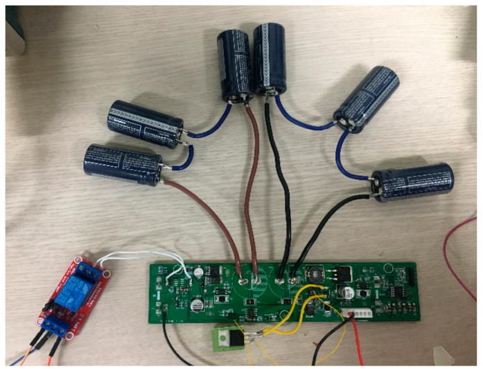
For this paper, based on the algorithm of
Figure 4, a Printed Circuit Board (PCB) board for charging the compensator by use of the supercapacitor, as shown in
Figure 5, was manufactured. The supercapacitors used were six units with 2.8 V/120 F arranged in series, and the MCU used for signal transmission was of Microchip’s picket series. The system in
Figure 5 includes a flyback booster circuit, a supercapacitor balancing circuit, a current sensor, and a voltage sensor.
3.3.2. MPPT
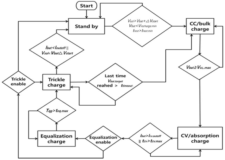
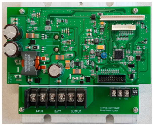
The supercapacitor integrator proposed in this paper is connected to a controller. For this purpose, an MPPT controller was manufactured;
Figure 6 and
Figure 7 show the MPPT circuit and the operating algorithm used for the experiment. The MPPT algorithm is controlled largely in four states as follows:
Idle Mode: This is the initial state of the controller, and charging starts in CC mode unless the voltage of the photovoltaic panels is high enough and the battery is full.
CC Mode: The battery is charged with full current until it reaches the CV voltage limit.
CV Mode: In the case of a lead–acid battery, the charging is conducted by use of a slightly higher charging voltage. After reaching the current limit or the time limit, the charger enters trickle or equalization mode in the case of a lead–acid battery, standby mode in the case of a lithium ion battery.
Trickle Charging Mode: On the trickle charging mode, the battery maintains a fully charged state in the case of a lead–acid battery. If the battery consumes a lot of power, the charger switches back to the CC/bulk charging mode.
4. Experiment and Results
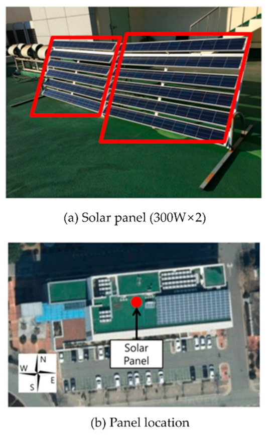
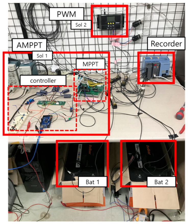
In order to confirm the performance of the proposed system, an experiment was conducted using two methods. A performance comparison was conducted using an existing solar charge controller (PWM) selling on the market and a charger equipped with the integrator presented in this paper (hereafter AMPPT:Accumulation-MPPT). The photovoltaic panels used in the experiment were two identical models of the 300 W class, and will be referred to as Solar1 and Solar2, respectively.
Solar1 and Solar2 were connected to an AMPPT and a PWM charger, respectively. As the batteries for charging, batteries with a capacity of 250 Ah were used; each battery will be referred to as Bat1 and Bat2, respectively. The state-of-charge (SOC) values of the batteries before and after charging were recorded using a TES33 product (battery capacity tester), and the SOC reference value was set as follows: High Limit V = 12.80 V, Low Limit V = 11.00 V, High Limit R = 4.250 mΩ, Low Limit R = 2.500 mΩ. For data collection using Yokogawa’s ‘SMARTDAC+ GM Data Acquisition’, the data of the voltage and of the current was collected in 1/10 s increments.
The charging experiment was conducted twice. A charging controller (MPPT) without an accumulation-type controller and with general charging controller (PWM) charging experiment (Case 1) was conducted first, and then the AMPPT and PWM charging experiment (Case 2) was conducted the next day. The weather in Case 1 was sunny, and the weather in Case 2 was rainy.
First, before starting the charging, the remaining amount of battery was measured by use of a TES33. In Case 1, the battery SOC before charging was as follows: Bat1
= 34% and Bat2 = 31%. The experiment time was from 6:00 to 17:00, and during the time of the experiment, the power of the PV panels was measured. In Case 2, the battery SOC before charging was as follows: Bat1 = 50% and Bat2 = 49%. The experiment time was from 07:00 to 17:30.
Figure 8 shows the PV panels used in the experiment and the installation location, and
Figure 9 shows the experiment environment.
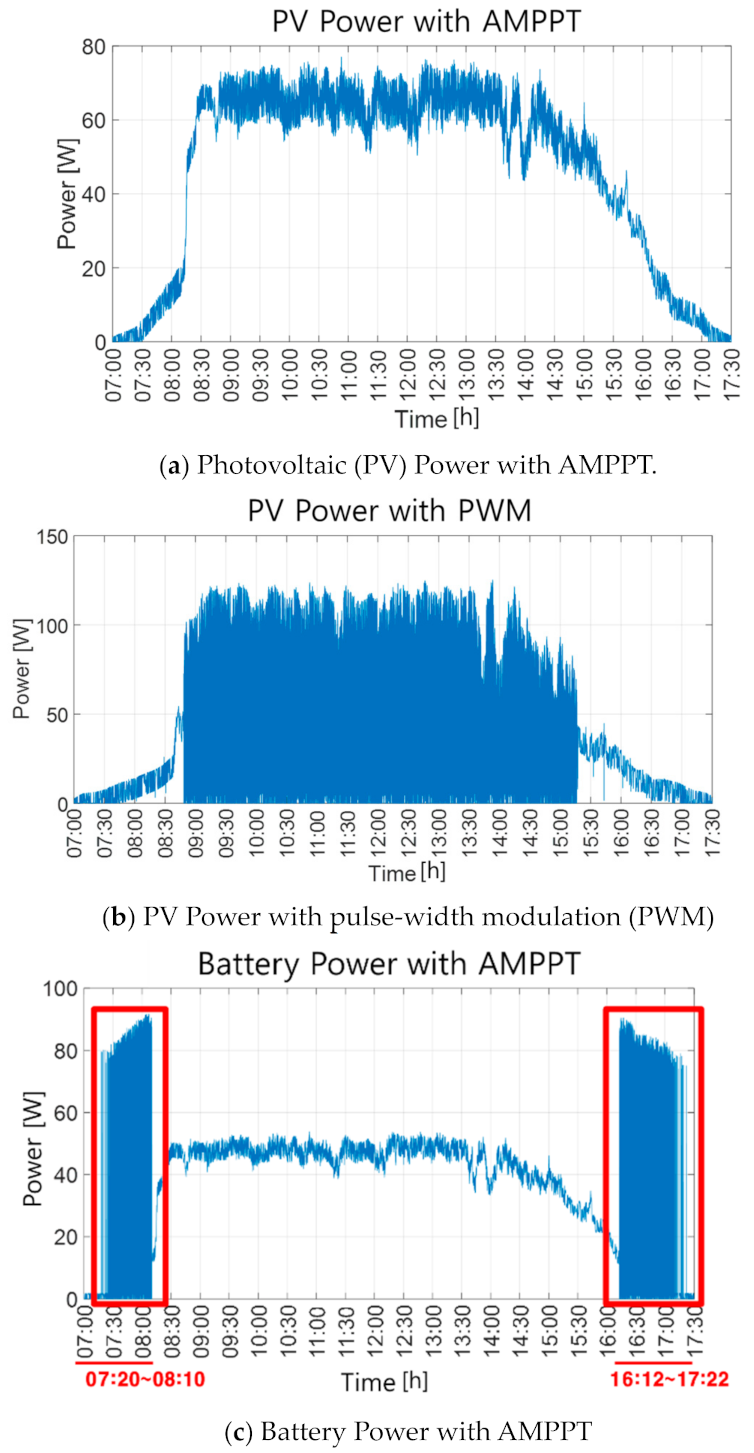
Figure 10 is a graph showing the trend of the power generation of one day, produced by Solar1 and Solar2.
Figure 10a is the power trend graph represented by the photovoltaic panels on the AMPPT side, and
Figure 10b is a power trend graph represented by the photovoltaic panels on the PWM side. In both graphs of
Figure 10a,b, it can be seen that the power generation for sections of approximately 1 h and 30 min in the morning and in the evening is lower than that of the midday sections.
Figure 10c is a graph showing the accumulation-type controller operation in the low-power section of AMPPT.
It can be seen that the accumulation-type controller operates in the morning and in the evening, during the low-illumination section, to transmit high power to the storage device. After the experiment was completed, the power stored in Bat1 and Bat2 was recorded through SOC measurement by use of TES33.
Table 1 and
Table 2 show the battery efficiency before/after experiment.
5. Result Analysis
Figure 10c confirms that the integrator operated from 7:20 am to 8:10 am and from 4:12 pm to 5:22 pm, when power was generated insufficiently due to the weak sunlight.
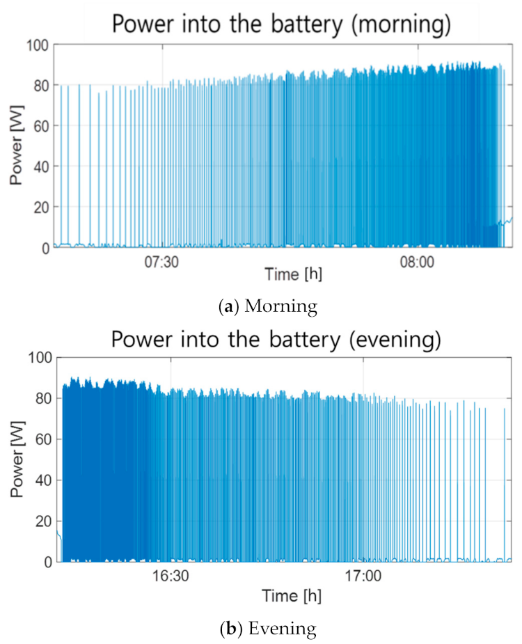
The graphs for the corresponding hours are enlarged in
Figure 11a,b. First, the graph in
Figure 11a is an operation graph from the morning hours (7:20–8:10). As the sunlight gets stronger over time, the power is charged rapidly to the capacitors, so the frequency of the power dissipation of the capacitors increases. It can be confirmed that when the output power of the photovoltaic panels becomes 10 W or higher, the integrator stops operating, and enters the normal charging mode.
The graph in
Figure 11b is an operation graph from the evening hours (16:12–17:22). It can be seen that when the power drops below 10 W, as the sunlight weakens over time, the integrator starts operating again. It can be confirmed that the frequency of the power dissipation of the capacitor slows down as the sunlight becomes weaker, and that it takes more time for the capacitor to gradually charge the battery.
In the low-power section, the output of the photovoltaic panels is insufficient, so it is difficult to charge the battery and the efficiency drops greatly. By storing this low-power energy in a capacitor rather than in the battery, it is possible to secure the surplus energy. Looking at
Table 1 and
Table 2, the difference of SOC before/after charging between an integration-type controller and a common controller can be confirmed.
SOC of Bat1 before charging was 50%, and SOC of Bat1 after charging was 61%; there occurred an 11% Point increase. SOC of Bat2 before charging was 49%, and SOC of Bat2 after charging was 54%; there occurred a 5% Point increase. By comparing the charging ratio over the same duration, it can be seen that the increase is 6% greater with an accumulation-type controller than it is with a general charging controller.
Table 1 shows a comparison of MPPT and PWM, and
Table 2 shows a comparison of AMPPT and PWM. The SOC difference between (A) MPPT and PWM, in
Table 1 and
Table 2, is 4% P and 6% P, respectively, that is, the results in
Table 1 and
Table 2 differ by 2% P. An SOC of 2% for a 250 Ah battery is about 60 Wh, which is about 5% of the 1200 W of power generated by a 300 W PV panel for 4 h per day.
6. Conclusions
In this paper, we proposed a system which can harvest the energy of the low-power section through an integral controller, by use of a supercapacitor. It was confirmed that in the morning and evening hours, when the amount of sunlight was insufficient, the supercapacitor integral controller operated to store energy in the supercapacitor, and the power was transmitted to the battery at high power by means of the fast charging/discharging characteristics of supercapacitor. It was also confirmed, through SOC measurement, that the charging method of using the supercapacitor integration controller stored 6% more energy than the normal charging method.
When using an integral controller by use of a supercapacitor, the energy storage ratio was higher than that of a normal charging controller, but the instantaneous high power is applied continuously to the battery, which can cause damage to it. In the future, this problem will be improved by controlling the power at the time of capacitor discharge transferal to battery.
This system was proposed based on a photovoltaic harvester, but, based on these findings, it can be applied not only to solar energy, but also to other energy harvesting systems, and it is expected that the efficiency can be further improved through the estimation and stabilization of the capacitor capacity.


