Article

A Novel Model Predictive Direct Torque Control Method for Improving Steady-State Performance of the Synchronous Reluctance Motor

1
Key Laboratory of Road and Traffic Engineering of the State Ministry of Education, Shanghai 201804, China
2
Key Laboratory of Rail Infrastructure Durability and System Safety, Tongji University, Shanghai 201804, China
3
College of Transportation Engineering, Tongji University, Shanghai 201804, China
4
National Maglev Transportation Engineering R&D Center, Tongji University, Shanghai 201804, China
*
Author to whom correspondence should be addressed.
Energies 2021, 14(8), 2256; https://doi.org/10.3390/en14082256
Submission received: 13 March 2021 / Revised: 12 April 2021 / Accepted: 15 April 2021 / Published: 17 April 2021

Abstract

:
Due to the particularity of the synchronous reluctance motor (SynRM) structure, a novel high-performance model predictive torque control (MPTC) method was proposed to reduce the high torque ripple and improve the performance and efficiency of the motor. First, the precise parameters of the SynRM reflecting the magnetic saturation characteristics were calculated using finite element analysis (FEA) data, and the torque and flux linkage maximum torque per ampere (MTPA) trajectory was derived by considering the saturation characteristics. Then, an MPTC model of a SynRM with duty cycle control was established, the MTPA trajectory stored in a look-up table was introduced into the control model, and the duration of the active voltage vector in one control cycle was calculated by evaluating the torque error. Finally, an experimental platform based on a SynRM prototype was built, and various performance comparison experiments were carried out for the proposed MPTC method. The experimental results show that the proposed method could reduce the torque ripple of the motor, the performance of the motor was significantly improved under various working conditions, and its correctness and effectiveness were verified.

1. Introduction

Recently, the synchronous reluctance motor (SynRM) has received extensive attention due to its advantages of having a low cost, ruggedness, high reliability, high efficiency, and good torque performance. Compared with the induction motor (IM), the SynRM has a higher power density and efficiency [1,2,3]. Due to the absence of expensive rare-earth magnets, the SynRM is not sensitive to the operating temperature, and its cost is lower than that of permanent magnet synchronous motors (PMSMs) [4,5]. Therefore, the SynRM is a potential alternative to the IM and PMSM in many industrial applications. Due to the particularity of the rotor topology, SynRM drives need high-performance control strategies.
The direct torque control (DTC) method directly controls the flux linkage and torque of the motor [6,7,8,9,10], which can meet the SynRM’s requirements of higher anti-interference ability and a fast dynamic response [8,9,10]. However, the torque and flux linkage ripples generated by the traditional DTC method are large, which causes mechanical vibrations and noise and reduces the service life of the motor and load. An effective method for reducing the torque ripple is to optimize the control algorithm of the motor drive system. In [11,12,13,14], it was shown that the DTC method combined with the space vector modulation (SVM) method can more accurately control the torque and magnetic flux, which reduces the torque and flux linkage ripples. However, the existing rotating coordinate transformation link weakens the fast dynamic response of the traditional DTC method. A method of applying duty cycle control to DTC was proposed to alleviate the problems of torque and flux linkage ripples in the applications of PMSMs and IMs [15,16]. However, when the above methods are applied to a SynRM [17,18], the torque ripple is still very high, which cannot meet industrial requirements. More recently, due to the advantages of its fast response and the ability to handle multiple variables and nonlinear constraints, model predictive torque control (MPTC) has received increasingly more attention regarding a broader range of applications in IMs [19,20], PMSMs [21,22], and SynRMs [23,24]. MPTC can predict the future torque and flux linkage in multiple control cycles based on a discrete system model. The optimal vector that is selected by minimizing the cost function in MPTC is more accurate and effective than using the DTC method. However, similar to DTC, only one voltage vector is applied during the entire control cycle, and thus it still has high torque and flux linkage ripples.
To improve the state-steady performance of MPTC, the duty cycle control method is introduced into MPTC, which applies an active vector and a zero vector during the same control cycle [21,25,26], and the duration of the active vector is determined using various optimization targets to reduce the torque ripple. In [25], the duration of the active vector was calculated based on the principle of deadbeat torque control. In [21,26], a novel duty cycle regulation method of MPTC that considered both the torque and stator flux linkage error information was proposed to vary the duration of the voltage vector using mathematical derivations. Some improved duty cycle methods have proposed that the vectors applied in a control period are not limited to an active vector and a zero vector but can be two active vectors [27,28,29]. Although the effect of the ripples is lower than when using previous methods, the complexity of the calculation process of these methods is significantly higher.
The above-mentioned MPTC methods that are based on duty cycle control and other improved methods have been applied to PMSMs and IMs. To our best knowledge, few papers have reported the applications of MTPC with duty cycle control to SynRMs. Furthermore, the parameters of a SynRM exhibit significant nonlinearity due to the magnetic saturation and cross-coupling magnetization. In MPTC, the influence of the nonlinearity of a SynRM on the accuracy of the parameters must be considered, though it has often been ignored or simplified in previous studies. To improve the efficiency performance and reduce the loss, the maximum torque per ampere (MTPA) strategy is often introduced into the SynRM control strategy. In [10,11,30], the MTPA strategy was merged with a conventional DTC algorithm. However, the inherent magnetic saturation characteristics and inductance changes of the SynRM were ignored, and the MTPA trajectory obtained by setting the current angle of the MTPA algorithm to 45° was not accurate [31]. Therefore, when using the MTPA algorithm, the saturation characteristics of the SynRM must be considered.
In this study, a novel optimized MPTC strategy for a SynRM was proposed and combined with the online MTPA strategy to improve the steady-state performance. The contributions of this article are as follows: the duty cycle control method was introduced in MPTC for a SynRM; an accurate MPTC model was established based on the parameters reflecting the magnetic saturation effect obtained using finite element analysis (FEA) data of the motor; the duration of the active vector was calculated by evaluating the torque error, thereby reducing the torque and flux linkage ripples; the torque–flux MTPA trajectory was derived by considering the saturation characteristics and then stored in a look-up table (LUT) for online tracking to generate the accurate flux linkage commands required by MPTC.
The rest of this paper is organized as follows. In Section 2, the mathematical model and nonlinearity of a SynRM are introduced, and the derivation of the MTPA trajectory is given by considering the magnetic saturation. The proposed MPTC method with duty cycle control of a SynRM is introduced in detail in Section 3. In Section 4, the experimental results of the proposed MPTC are presented and discussed. The conclusion of the paper is presented in Section 5.

2. Mathematical Model and Nonlinearity of a SynRM

2.1. Mathematical Model

The SynRM model in the synchronous dq frame with the d-axis aligned along the direction of minimum reluctance is given by
u s = R s i s + ω e J ψ s + d ψ s d t ,
where us = (ud, uq)T, is = (id, iq)T, and ψs = (ψd, ψq)T are the stator voltages, currents, and flux linkages, respectively; Rs is the resistance of the stator windings; ωe = m is the electromechanical rotor speed, with p denoting the number of motor pole pairs and ωm denoting the mechanical rotor speed; J = [ 0 1 1 0 ] is the orthogonal rotation matrix.
The electromagnetic torque Te produced by the motor is given as follows:
T e = 3 2 p ( i s ) T J ψ s .
The mechanical motion equation of the motor is expressed as follows:
{ d ω m d t = 1 J m ( T e T L ) B m J m ω m d θ m d t = ω m ,
where Jm is the mechanical inertia, Bm is the viscous friction coefficient, TL is the generic load torque, and θm = θe/p is the rotor mechanical angle, where θe is the electrical-mechanical angle.

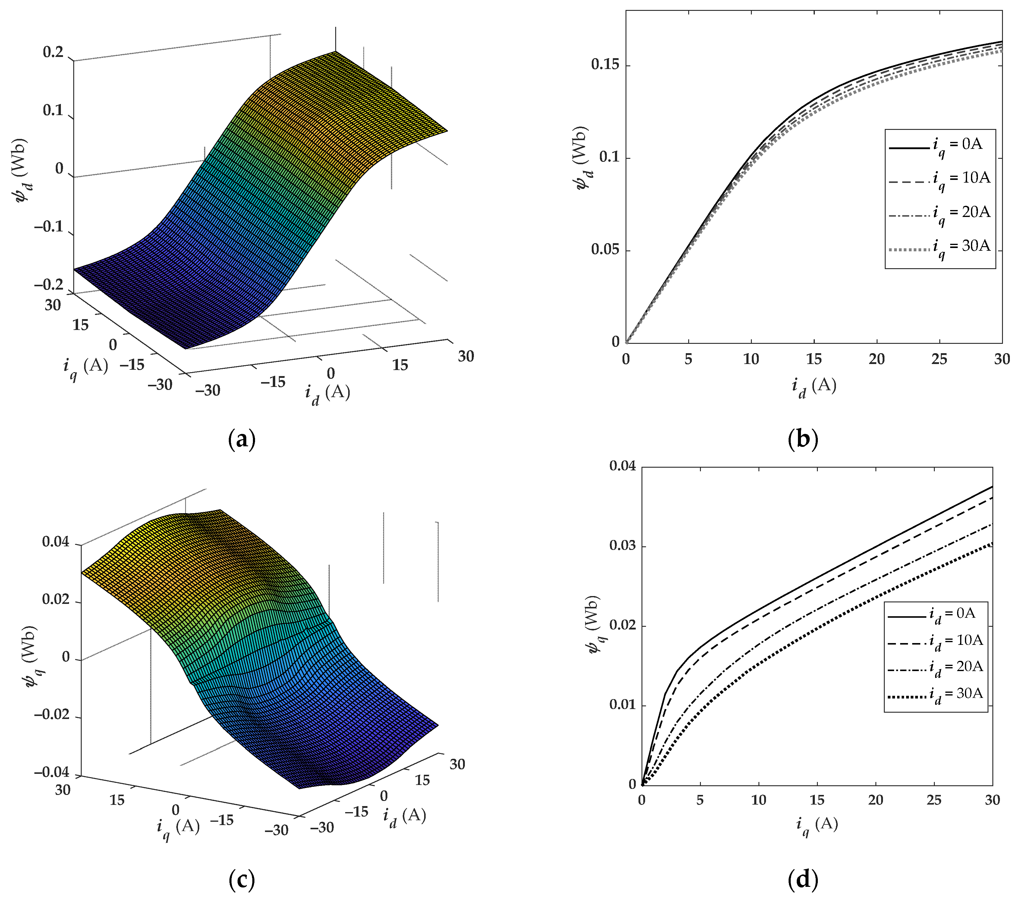
2.2. Nonlinearity of the SynRM

Due to the magnetic saturation and cross-magnetization effects of the magnetic circuit, the stator current and flux linkage have a highly nonlinear relationship, and both the flux linkages ψd and ψq are affected by both id and iq at the same time. As such, the general relationships between the stator currents is and the flux linkages ψs are expressed as follows:
ψ s ( i s ) = [ ψ d ψ q ] = [ ψ q ( i d , i q )   ψ q ( i d , i q ) ] .
FEA can simulate and calculate the parameters of the motor based on the distribution of the electromagnetic field in the motor. In this paper, circuit-field conversion time-step FEA is carried out for the 2 kW SynRM prototype. The internal structure and parameters of the motor are shown in Figure 1 and Table 1, respectively. Therefore, the relationships between the flux linkages ψs and the stator currents is for the 2 kW SynRM prototype given in (4) are shown in Figure 2, which can describe the magnetic saturation and cross-magnetization characteristics of the SynRM.
It can be seen from Figure 2 that as the currents increased, the d- and q-axis flux linkages both showed significant nonlinear behavior and were affected by cross-magnetization, especially the q-axis flux linkage ψ q ( i d , i q ) .
It was also concluded that the q-axis current had a deeper effect on the d- and q-axis mutual inductances, whereas the d- and q-axis self-inductances were mostly affected by the current in the corresponding axis [31]. In this case, the inductances of the SynRM also exhibited nonlinear characteristics, where the values were not constant. Therefore, the apparent and incremental inductances were introduced to achieve precise control of the motor.
The apparent inductances matrix L s a i ( i s ) is expressed as follows:
L s a i ( i s ) = [ L d a i ( i d , i q ) L q a i ( i d , i q ) ] = [ ψ d ( i d , i q ) / i d ψ q ( i d , i q ) / i q ] ,
where L d a i and L q a i denote the apparent inductances of the d- and q-axes, respectively.
The incremental inductances are defined as the derivative of the flux linkages with respect to the stator currents [32]; therefore, the incremental inductances matrix L s i i is expressed as follows:
L s i i ( i s ) = [ L d i i ( i d , i q ) L d q i i ( i d , i q ) L q d i i ( i d , i q ) L q i i ( i d , i q ) ] = [ ψ d ( i d , i q ) i d ψ d ( i d , i q ) i q ψ q ( i d , i q ) i d ψ q ( i d , i q ) i q ] ,
where L d i i and L q i i are the incremental inductances of the d- and q-axes, respectively, while L d q i i and L q d i i are the cross-magnetization inductances.
The apparent and incremental inductances were calculated offline using the flux linkages data obtained via FEM (as shown in Figure 1).
Combined with (6), the time derivative of the flux linkages in (1) can be expressed as
d ψ s d t = ψ s i s d i s d t = L s i i ( i s ) d i s d t .
Based on (1) and (7), the dynamics of the stator currents is given as follows:
d i s d t = L s i i ( i s ) 1 ( u s R s i s ω e J ψ s ) ,
where the inverse of the incremental inductance matrix is given as follows:
L s i i ( i s ) 1 = 1 det ( L s i i ( i s ) ) [ L d i i ( i d , i q ) L d q i i ( i d , i q ) L q d i i ( i d , i q ) L q i i ( i d , i q ) ] .
The flux linkages and inductances could be interpolated using 2D LUTs, which were used for the online real-time control of the SynRM. Therefore, the actual flux linkages and incremental inductances were tracked online according to the actual current measurements via LUTs.

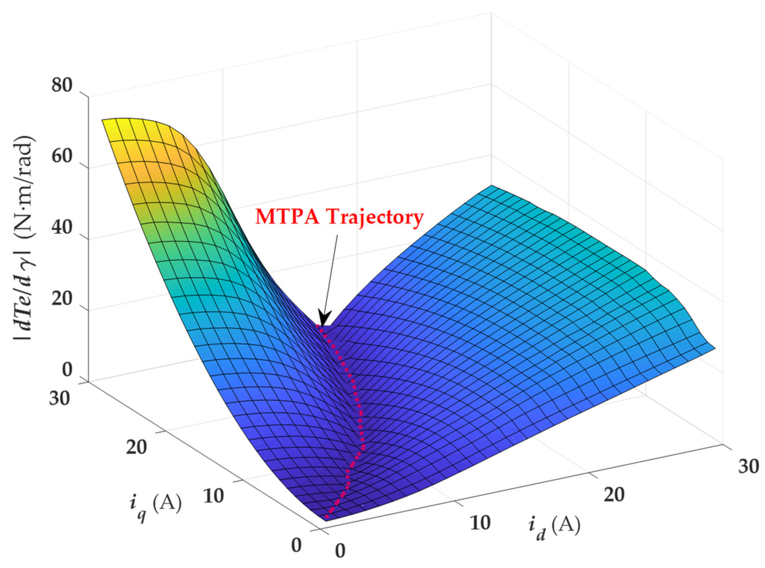
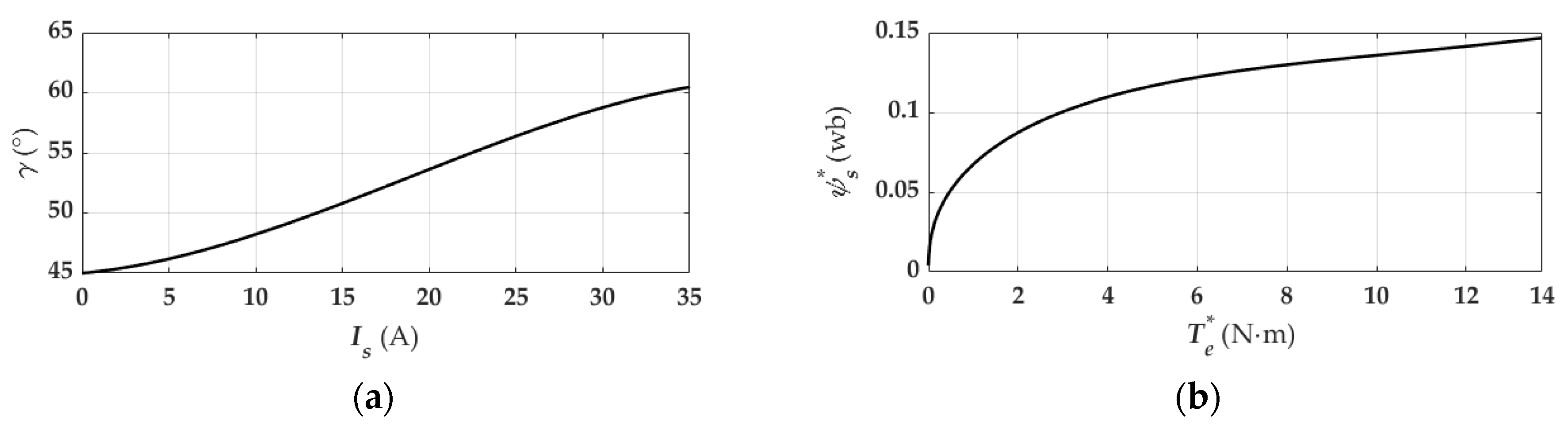
2.3. MTPA Trajectory

The MTPA algorithm can achieve the maximum torque output with the given stator current and minimize the copper loss of the motor. However, due to the saturation characteristics of a SynRM, the MTPA trajectory obtained using the fixed current angle γ ( γ = 45 ) is not accurate and cannot reflect the actual operation state of the motor. In this study, the accurate MTPA trajectory could be calculated offline according to the LUTs of the flux linkages and inductances obtained using the FEA data by considering the saturation characteristics.
For a given stator current i s , the derivative of the torque with respect to the optimal current angle is zero. According to (2), the derivative of the torque with respect to the current is obtained as follows:
d T e d γ = 3 2 ( ( d i s d γ ) T J ψ s + ( i s ) T J d ψ s d γ ) = 3 2 p ( d ψ d d γ i q + d i q d γ ψ d d ψ q d γ i d d i d d γ ψ q ) .
Since the current angle γ is the angle between the stator current and the d-axis, the d-axis current i d = i s cos γ and the q-axis current i q = i s sin γ . Then, the derivatives of the d- and q-axis currents with respect to the current angle can be expressed as follows:
{ d i d d γ = d ( i s cos γ ) d γ = i q d i q d γ = d ( i s sin γ ) d γ = i d
After combining with (6), the derivatives of the d- and q-axis flux linkages with respect to the current angle are given as follows:
{ d ψ d d γ = ψ d i d d i d d γ + ψ d i q d i q d γ = L d i i i q + L d q i i i d d ψ q d γ = ψ q i d d i d d γ + ψ q i q d i q d γ = L d q i i i q + L q i i i d
Substituting (11) and (12) into (10), the derivative of the torque with respect to the current angle in terms of the flux linkages and incremental inductances is expressed as follows:
d T e d γ = 3 2 p ( ψ d i d + ψ q i q L d i i i q 2 L q i i i d 2 + 2 L d q i i i d i q ) .
The d T e / d γ defined in (13) is a function of i d and i q . The ψ d and ψ q are obtained from the FEA data, and L d i i , L q i i , and L d q i i are obtained by using (6) and ψ d and ψ q . The surface of d T e / d γ that was calculated using (13) is given in Figure 3. The MTPA trajectory is located at the points where the derivative of the torque with respect to the current angle is zero in Figure 3, which is the bottom of the valley. According to the relationship between i d and i q on the MTPA trajectory in Figure 3, the MTPA trajectory of the stator current i s and the current angle γ was calculated and is shown in Figure 4a.
In the MPTC algorithm, the reference stator flux linkage ψ s * is determined using the reference torque T e * , which is obtained via the speed control loop. Therefore, it is necessary to obtain the relationship between the torque and the flux linkage by considering the saturation characteristics of the motor. Using (2), the flux linkage LUTs, and the current–angle trajectory in Figure 4a, the accurate MTPA trajectory characterizing the relationship between the torque and flux linkage was obtained, as shown in Figure 4b; it was then stored in the LUT for online real-time control.

3. Proposed MPTC Method with Duty Cycle Optimization

The overall control diagram of the proposed MPTC method based on MTPA is shown in Figure 4 and is mainly composed of the following parts: the MPTC module, the external speed control loop, the coordinate transformation, the flux linkage and torque estimations, the inductance estimations, and the pulse generation. The torque reference T e * is obtained via the speed control loop using the proportional–integral (PI) controller, and the reference stator flux linkage ψ s * is obtained from the reference torque T e * through the MTPA trajectory LUT that was calculated offline using FEA data, as discussed in Section 2.3. MPTC involves torque and flux predictions, cost function minimization, and a duty cycle optimization module for the active vector for suppressing torque ripples. The apparent and incremental inductances, the flux linkages, and the torque of the motor can be estimated through the LUTs and the real-time currents in the current control cycle. The details of each part in Figure 5 are elaborated upon in the following text.

3.1. Prediction Model and Cost Function Minimization

The first-order Euler discretization is used to discretize the continuous-time model of the motor, and the prediction model of the stator currents can be obtained from (8), which is followed by
i s k + 1 = i s k + L s i i ( i s k ) 1 ( u s k R s i s k ω e k J ψ s k ) t s ,
where t s is the control period (sampling interval), the superscript k indicates the measured or estimated values at the kth instant, and the superscript k + 1 indicates the predicted values at the (k + 1)th instant. The flux linkages ψ s k are estimated by the flux linkages’ LUTs and the measured currents i s k . Using (1), the discretization prediction model of the flux linkages at the (k + 1)th instant can be expressed as follows:
ψ s k + 1 = ψ s k + ( u s k R s i s k ω e k J ψ s k ) t s .
The electromagnetic torque is predicted using
T e k + 1 = 3 2 p ( i s k + 1 ) T J ψ s k + 1 .
The purpose of the MPTC method is to enable the torque and flux linkage to follow the corresponding reference command values and to minimize the torque and flux linkage errors at the end of the next control cycle. The cost function that evaluates the errors between the reference values and the prediction values of the torque and flux linkage is defined as follows:
{ g | u i = u 0 , , 6 = | T e * T e k + 1 | + κ ψ | | ψ s * | | ψ s k + 1 | | | ψ s k + 1 | = ( ψ d k + 1 ) 2 + ( ψ q k + 1 ) 2 ,
where κ ψ is the weighting factor that is assigned the same weight to both the torque and flux linkage.
For the two-level inverter-fed SynRM drives, there are eight voltage vectors to choose from in the predictive control cycle, including six active voltage vectors ( u 1 , , u 6 ) and two zero vectors with the same effect ( u 0 , u 7 ). Among these feasible vectors, the one that minimizes the cost function (17) is selected as the most optimal voltage vector, as shown in (18):
u s o p t = argmin   g | u i = u 0 , , 6 ,
where u s o p t is the optimal voltage vector in the (k + 1)th control period.
In the conventional MPTC method, only one voltage vector is selected in the whole control cycle. Since this voltage vector will affect the entire control cycle, it may cause an overadjustment of the torque in the steady state, resulting in a large torque ripple. Considering that the torque change rate generated by the zero vector u s 0 is relatively small, if a zero vector and a non-zero active vector u s a are applied in the same control period, the torque ripple can be effectively reduced by adjusting the duty ratio of the effective voltage vector and using the smoothing effect of the zero vector on the torque. As a result, the steady-state performance of the motor will be significantly improved.

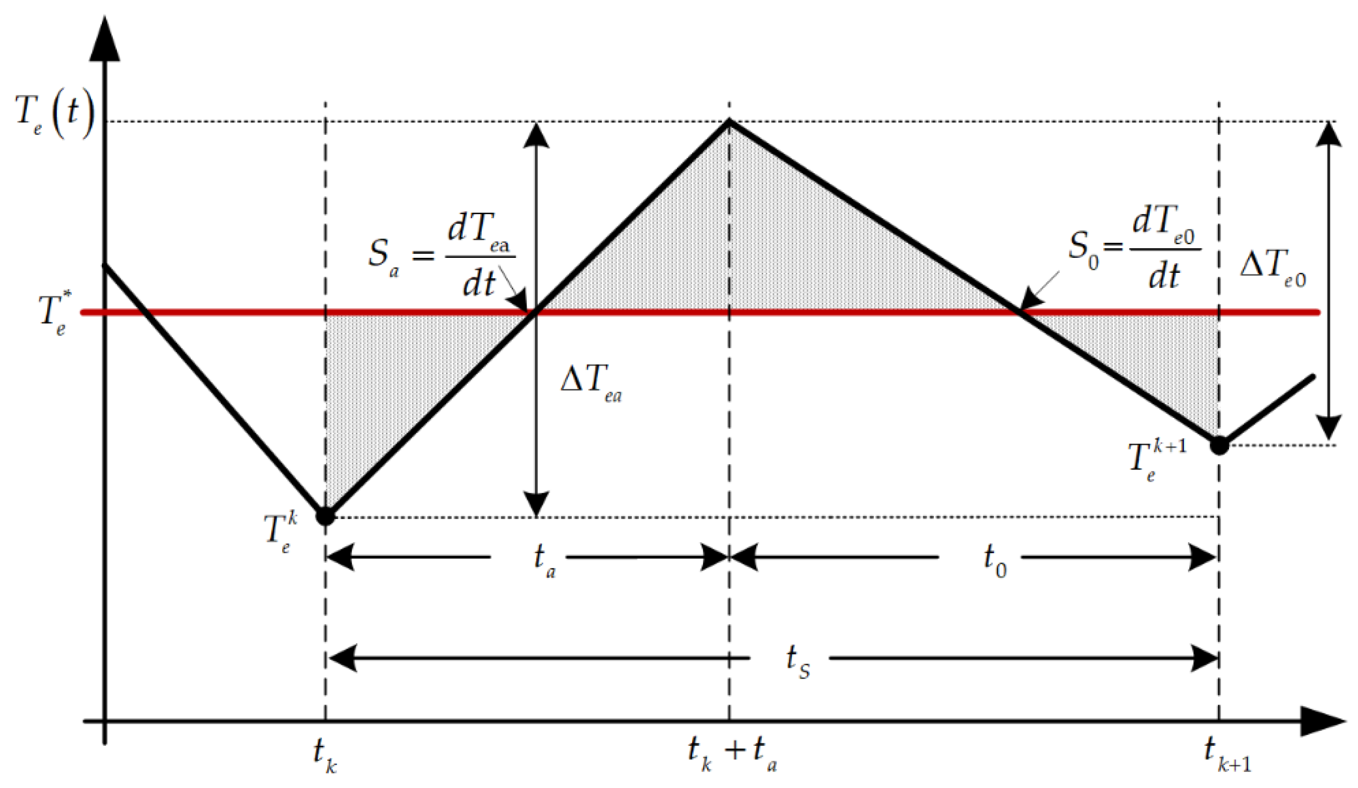
3.2. Torque Ripple Suppression with Duty Cycle Control

If the optimal voltage vector is an active vector, its duty cycle is calculated according to the magnitude of the torque ripple.
According to (2), the derivative of the torque can be obtained as follows:
d T e d t = 3 2 p ( ( d i s d t ) T J ψ s + ( i s ) T J d ψ s d t ) .
Substituting (1) and (8) into (19), when a different voltage vector is applied to the motor, the rate of change of the torque is obtained as follows:
d T e d t = 3 2 p ( L s i ( i s ) 1 ( u s R s i s ω e ψ s ) T J ψ s + ( i s ) T J ( u s R s i s ω e J ψ s ) ) .
Figure 6 shows the torque ripple from the active voltage vector and the zero voltage vector in the (k + 1)th control period.
In Figure 6, T e k is the torque at the beginning of the (k + 1)th control period, T e k + 1 is the torque at the end of the (k + 1)th control period, S a is the slope of the torque from the active vector, t a is the duration of the active vector in the (k + 1)th control period, Δ T e a = t a S a is the torque increment during the duration t a ( t a t s ), S 0 is the slope of the torque from the zero vector, t 0 is the duration of the zero vector in the (k + 1)th control period, and Δ T e 0 = t 0 S 0 is the torque decrement during the duration t 0 ( t 0 = t s t a ).
Due to the very small t s , the slopes S a and S 0 can be considered to be invariant during the (k + 1)th control period. According to (20), the slopes S a and S 0 are expressed as follows:
S a = d T e a d t = 3 2 p ( L s i i ( i s ) 1 ( u s a R s i s ω e ψ s ) T J ψ s + ( i s ) T J ( u s a R s i s ω e J ψ s ) ) ,
S 0 = d T e 0 d t = 3 2 p ( L s i i ( i s ) 1 ( R s i s + ω e ψ s ) T J ψ s + ( i s ) T J ( R s i s + ω e J ψ s ) ) .
In the (k + 1)th control period, the torque change with time can be expressed as follows:
T e k + 1 ( t ) = { T e k + S a ( t t k ) t k t t k + t a T e k + S a t a + S 0 ( t t k ) S 0 t a t k + t a t t k + 1
The square of the root mean square (RMS) of the torque error (shaded area in Figure 5) is used to evaluate the torque ripple in the (k + 1)th control period, which is obtained using (23) as follows:
( T e ( R M S ) error ) 2 = 1 t s t k t k + 1 ( T e error ) 2 d t = 1 t s t k t k + 1 ( T e k + 1 ( t ) T e * ) 2 d t = 1 t s t k t k + t a ( T e k T e * + S a ( t t k ) ) 2 d t + 1 t s t k + t a t k + 1 ( T e k T e * + S a t a S 0 t a + S 0 ( t t k ) ) 2 d t
( T e ( R M S ) error ) 2 is a function of t a . In order to minimize the torque ripple during the (k + 1)th control period, the optimal duration of the t a period should satisfy (25):
( T e ( R M S ) error ) 2 t a = 0 .
By solving (25), the optimal duration of t a can be obtained as follows:
t a o p t = 2 T e * 2 T e k S 0 t s 2 S a     S 0 .
There are three cases for the optimal duration t a o p t :
(1)
If the optimal duration t a o p t obtained by (26) is in the range of [0, t s ], it means that the system is in a steady state. The active voltage vector is applied with a duration of t a o p t and the torque ripple is minimized.
(2)
If the calculated value of t a o p t is greater than t s , it means that the system is not in a steady state. In this case, the t a o p t is limited to t s and the active voltage will be applied for the whole control period to maintain the dynamic response of the system.
(3)
If the calculated value of t a o p t is less than 0, then make t a o p t = 0 and the zero vector will be applied in the whole control cycle.

3.3. Switching Frequency and Loss Reduction

To reduce the switching frequency and losses and improve the system efficiency, the appropriate zero vector u0 (000) or u7 (111) must be selected. The selection of the zero vector is conducted according to the principle of the lowest number of switch state changes corresponding to the active vector. When the active vector is u1 (001), u2 (010), or u4 (100), then u0 (000) is chosen as the zero vector, and when the active vector is u3 (011), u5 (101), or u6 (110), then u7 (111) is chosen as the zero vector. During the change from the active voltage to the zero vector voltage, only the state of one switch changes, which achieves the minimum amount of switching loss.

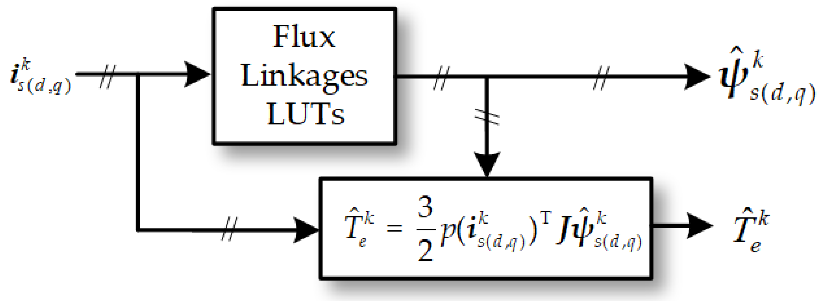
3.4. Torque and Flux Linkage Estimation

Precise torque and flux linkage estimations are required for the accurate operation of the MPTC method. The flux linkage and torque estimation method adopted in this article is shown in Figure 7. The flux linkages ψ ^ s ( d , q ) k at the kth instant are estimated online according to real-time measurements of the currents i s ( d , q ) k by using the flux linkage LUTs shown in Figure 2a,c. The torque T e k at the kth instant is obtained by substituting the estimated flux linkages and measurement currents into (2).

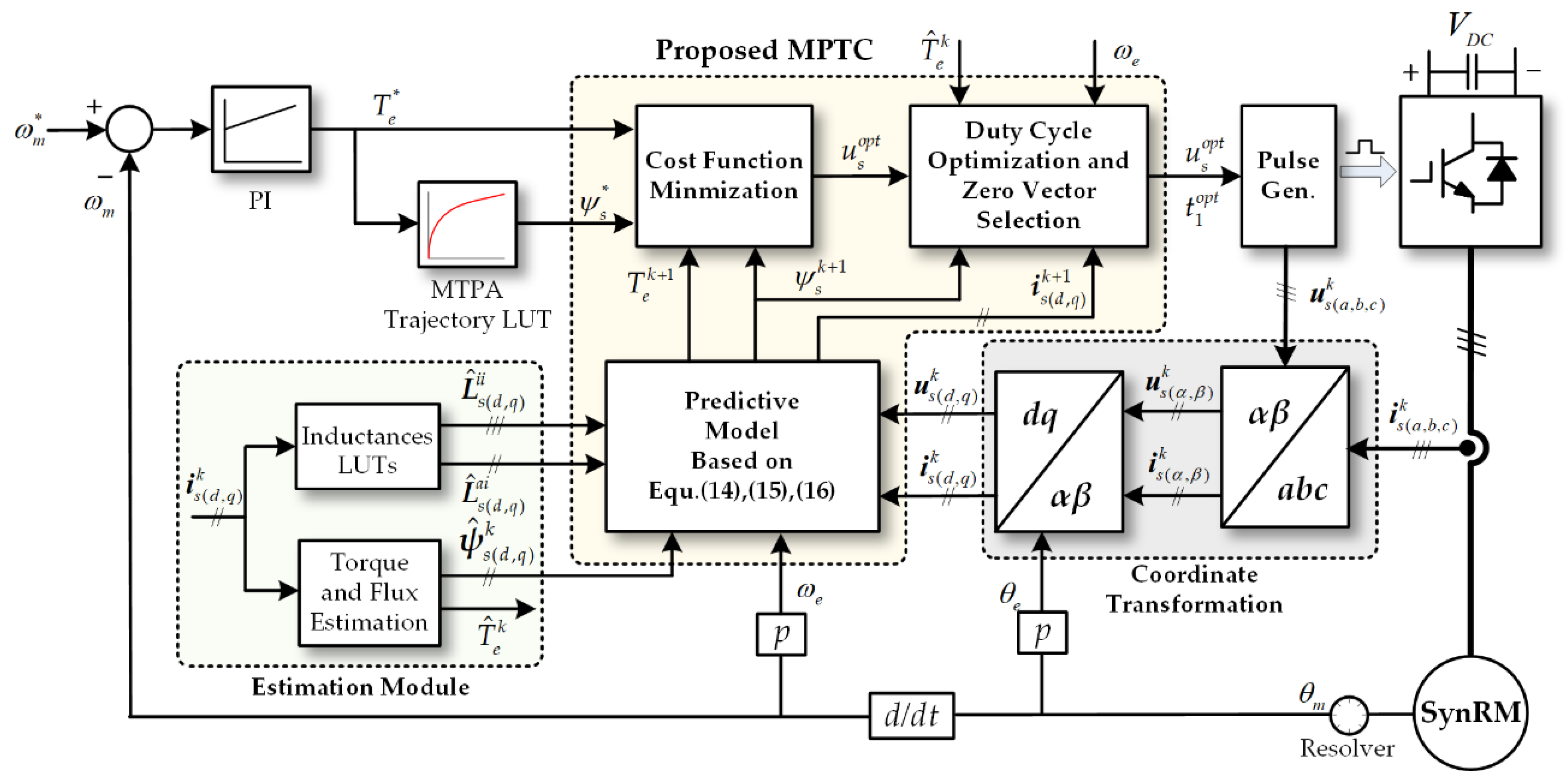
3.5. Calculation Sequence of the Control System

Combined with the control diagram shown in Figure 4, the following steps are used in the digital processor to implement the proposed control algorithm:
(1)
Measure i s ( a , b , c ) k and θ m , reconstruct the optimal voltage vector u s ( a , b , c ) k , and obtain ω m , ω e , and θ e by using θ m in the kth control period.
(2)
Transform i s ( a , b , c ) k and u s ( a , b , c ) k in the stationary abc reference frame into i s ( d , q ) k and u s ( d , q ) k in the synchronous dq reference frame.
(3)
Estimate ψ ^ s ( d , q ) k , T ^ e k , L s i i , and L s a i at the kth instant by using the LUTs and (2).
(4)
Calculate the reference torque T e * through the PI controller and obtain ψ s * by using the MTPA trajectory LUT of the torque–flux linkage.
(5)
Predict T e k + 1 , ψ s k + 1 , and i s k + 1 using (14), (15), and (16).
(6)
Evaluate the cost function g (17) for each voltage vector of the converter and select the voltage vector with the minimized value of the cost function as the optimal voltage vector u s o p t for the (k + 1)th control period.
(7)
Calculate the slopes S a and S 0 using (21) and (22) if u s o p t is an active vector u s a .
(8)
Obtain the optimal duration t a o p t from (26) applied to u s a and select the appropriate zero vector for the rest of the control period.

4. Experimental Platform and Results

4.1. Experimental Platform

An experimental platform based on the 2 kW SynRM prototype and MicroLabBox dSPACE was built to implement and validate the effectiveness of the proposed MPTC, as shown in Figure 8.
The specific configuration of the experimental platform was set up as follows. The 2 kW SynRM prototype was the same as the motor mentioned in Section 2.3, where its parameters are shown in Table 1. A hysteresis brake was used as the brake load. A torque sensor was installed on the shaft between the SynRM prototype and the hysteresis brake to measure the torque generated by the SynRM. A customized 55 kW three-phase inverter was powered by a 9 kW DC power supply to drive the motor. MicroLabBox dSPACE ds1202 with a 2 GHz dual-core real-time processor and programmable FPGA was used as the system controller for implementing the control algorithm, sending pulses to the inverter, and sampling and analyzing the information of the measured currents, position, and torque of the motor. In the experimental tests, the sampling time was chosen to be 100 μs.

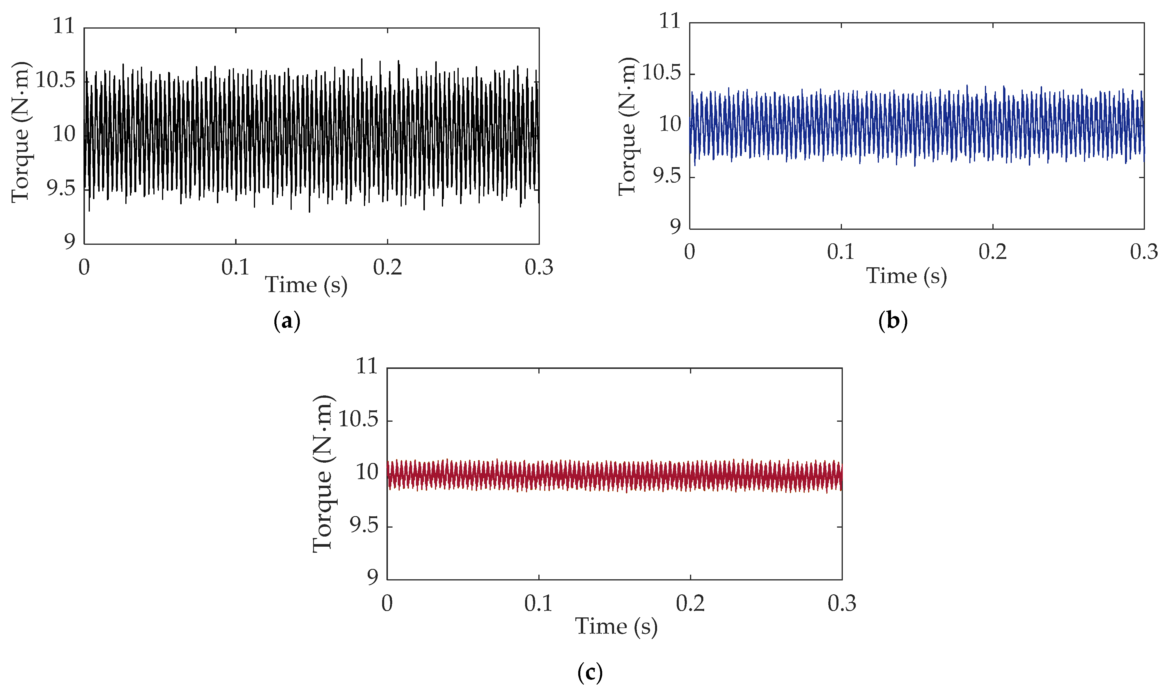
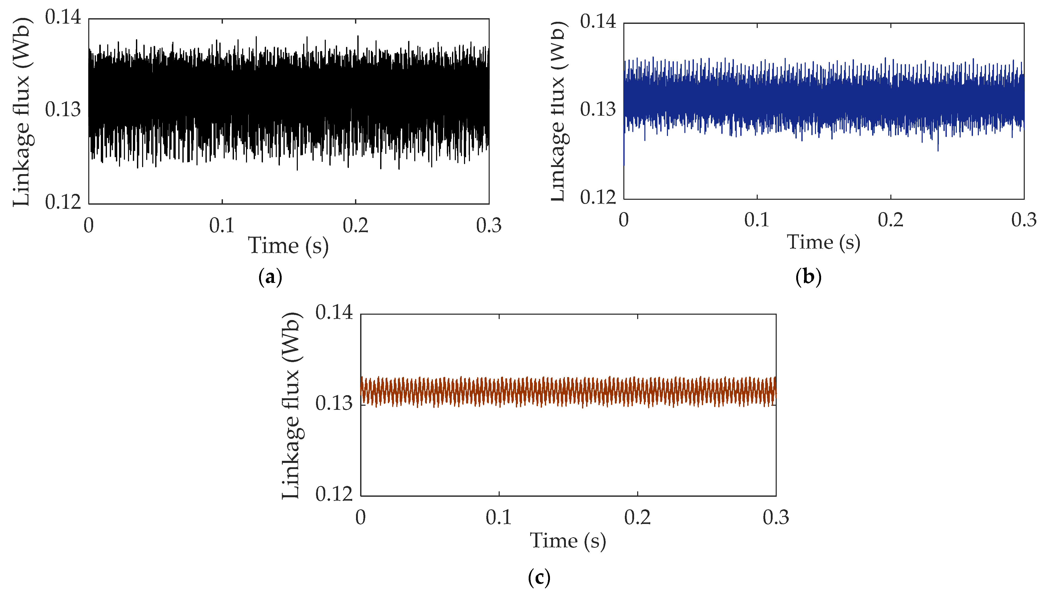
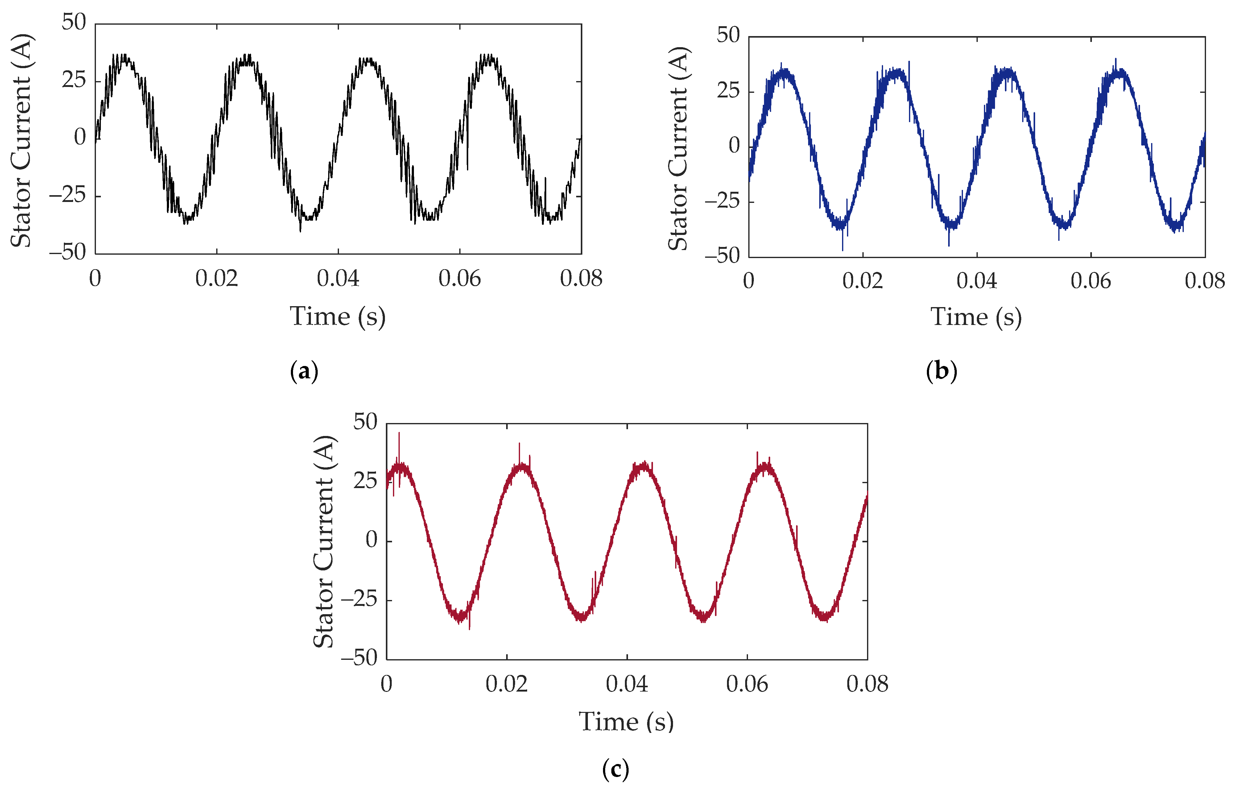
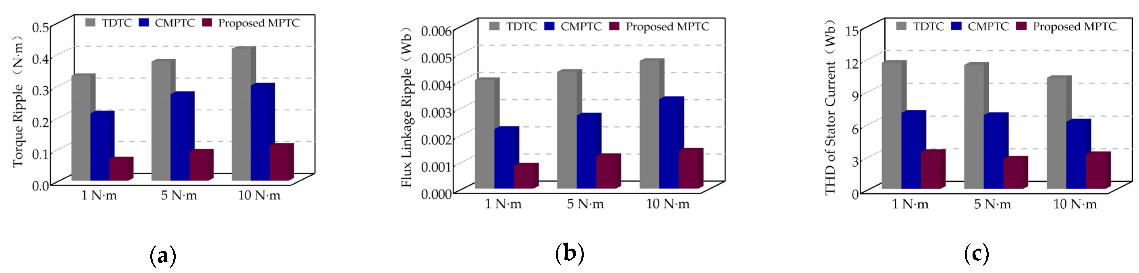
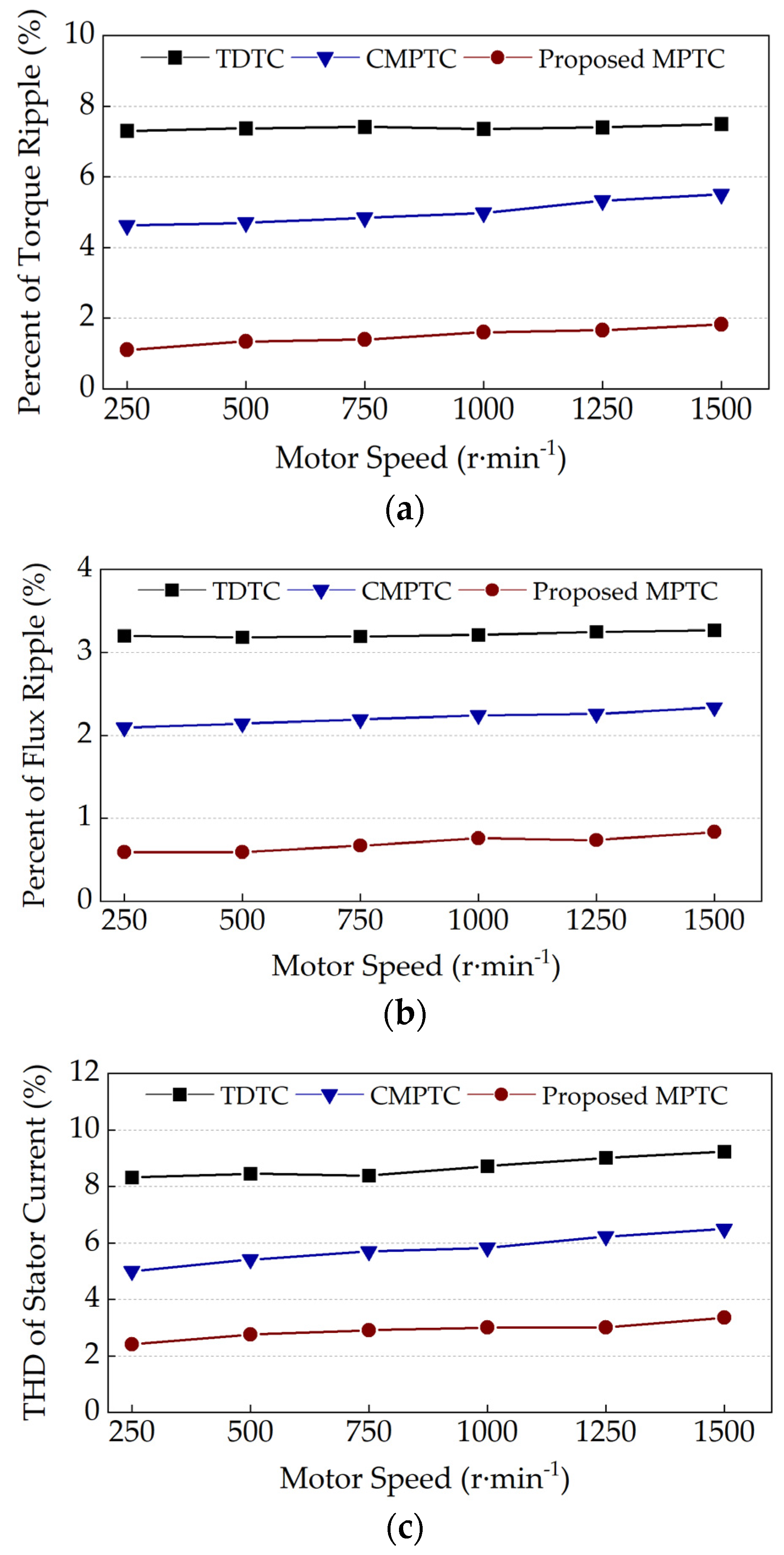
4.2. Torque and Flux Linkage Ripple Suppression Experiments

The proposed MPTC method was implemented on the experimental platform, and the experiments were carried out under various operating conditions of the motor. Furthermore, the performance of the proposed MPTC method was compared with the traditional DTC (TDTC) and conventional MPTC (CMPTC) methods. The steady-state performances of the torque and flux linkage ripples for the proposed MPTC, TDTC, and CMPTC methods were investigated and compared. The torque and flux linkage ripples were evaluated using the RMS values, which were calculated using
T e r i p p l e = 1 N i = 1 N ( T e ( i ) T e * ) 2 ,
ψ s r i p p l e = 1 N i = 1 N ( | ψ s ( i ) | ψ s * ) 2 ,
where N is the number of sampling points, T e * is the average torque value, and ψ s a v e is the average flux linkage value.
When the output torque from the motor was 10 N·m at the steady-state speed of 1500 r·min−1 (rated speed), the resulting torque, flux linkage, and stator current of the a-phase controlled by the three methods are shown in Figure 9, Figure 10 and Figure 11, respectively. The stator flux linkage ψ s = ( ψ d ) 2 + ( ψ q ) 2 and the estimations of ψ d and ψ q are shown in Figure 7.
It can be seen from Figure 9, Figure 10 and Figure 11 that the steady-state performance of the TDTC method was the worst. The RMS values of the torque and flux linkage ripples reached 0.37 N·m and 0.0043 Wb, respectively. The total harmonic distortion (THD) of the stator current was as high as 10.1%. Compared with the TDTC method, the steady-state performance was improved with the CMPTC method, where the RMS values of the torque ripple, flux ripple, and stator current THD were reduced to 0.276 N·m, 0.0031 Wb, and 6.4%, respectively. The proposed MPTC method had the best steady-state performance, and the torque and flux ripples were reduced to 0.095 N·m and 0.0012 Wb, respectively. Compared with the TDTC method, the RMS values of the torque and flux linkage ripples of the proposed MPTC method were reduced by 74.32% and 69.76%, respectively, and the stator current THD was reduced from 10.6% in the TDTC method to 3.2%. It was verified that the proposed MPTC could significantly improve the steady-state performance and reduce the torque ripples of the motor under high-speed and heavy-load conditions.
To study the influence of load changes on the steady-state performance of the methods, experiments involving light (1 N·m), medium (5 N·m), and heavy (10 N·m) loads applied to the motor at 1500 r·min−1 were carried out to compare the steady-state performances of the three methods. The comparisons of the torque ripple, flux linkage ripple, and stator current THD of the three methods are shown in Figure 12.
Figure 12 shows that the torque ripple, flux linkage ripple, and stator current THD of the proposed MPTC were still the smallest among the three methods under the different loads. The improvement effect of the steady-state performance under the light and medium loads was better than that under the heavy load.
To further compare the steady-state performances, experiments investigating the three methods were carried out at various motor operating speeds with a constant 5 N·m load. Figure 13 shows the comparison of the torque ripple, flux ripple, and stator current THD of the three methods at various speeds. The experimental results show that, in all speed ranges, the torque and flux ripple percentages and the stator current THD of the proposed MPTC were significantly smaller than those for the TDTC and CMPTC methods, i.e., the steady-state performance was greatly improved, especially in the low-speed range.

4.3. Performance Verification of the MTPA Trajectory by Considering the Saturation Characteristics

The experiments were conducted to verify the improvement in the MTPA trajectory by investigating the effect of the saturation characteristics on the motor’s performance, where the amplitudes of the stator current is with and without the saturation characteristics were compared under the same load condition, as shown in Figure 14. In the experiments, the motor was applied with 1 N·m, 5 N·m, and 10 N·m loads at 1500 r·min−1.
It can be seen from Figure 13 that when the motor load was 1 N·m, the stator current amplitudes under the two MTPA modes were basically the same and the motor was still unsaturated. The current angle in both modes was almost 45°. When the loads were 5 N·m or 10 N·m, the motor had different degrees of saturation and the current angles of the motor were 54.51° and 59.61°, respectively. The stator current amplitudes using the MTPA trajectory with saturation characteristics were 11.5% and 17.7% smaller than those of the MTPA trajectory without saturation characteristics, respectively.
The experimental results show that as the load increased, the motor gradually became saturated. The MTPA trajectory that was found when considering the saturation characteristics could accurately reflect the nonlinear characteristics of the motor under different working conditions; the stator current amplitude with the same torque was also smaller, which could further reduce the motor losses.

5. Conclusions

To improve the steady-state performance of a SynRM, this study introduced duty cycle control and the MTPA algorithm with saturation characteristics into the conventional MPTC method. Considering the highly nonlinear characteristics of synchronous reluctance motors, the motor parameters and MTPA trajectory with saturation characteristics were calculated using FEA data, and the active vector duration in one control cycle was calculated to reduce the torque ripple.
Through various experiments, the steady-state performance of this method was compared with the traditional DTC and conventional MPTC methods. The experimental results showed that the torque ripple, magnetic flux ripple, and THD of the proposed MPTC method under the rated speed and heavy-load conditions were reduced by 74.32% and 65.57%, 69.76% and 61.29%, and 68.31% and 50% compared with DTC and traditional MPTC, respectively. The steady-state performance of the motor at full speed and under various load conditions was significantly improved. Meanwhile, compared with the MTPA trajectory without the saturation characteristics, the MTPA trajectory with the saturation characteristics could more accurately reflect the working state of the motor in the saturation region, and the stator current amplitude was smaller. A series of experiments verified the effectiveness of the proposed MPTC method.
Further research is needed. The motor parameters with saturation characteristics used in the algorithm proposed in this study were based on FEA data, which requires that the specific internal structure, such as the geometry and winding configuration, of the motor is known. Therefore, in follow-up research, it is necessary to design a motor test experiment to obtain the parameters of the SynRM response saturation characteristics to make the proposed method universal for the SynRM.

Author Contributions

Conceptualization, Y.Z. and L.R.; methodology, Y.Z.; software, Y.Z.; validation, Y.Z., L.R., and Z.L.; data curation, Y.Z. and L.R.; writing—original draft preparation, Y.Z.; writing—review and editing, L.R. and Z.L.; visualization, G.L. All authors have read and agreed to the published version of the manuscript.

Funding

This research received no external funding.

Acknowledgments

This work was supported by a project of the Science and Technology Commission Shanghai Municipality (no. 17511102302).

Conflicts of Interest

The authors declare no conflict of interest.

References

  1. Almeida, A.T.; Ferreira, F.J.T.E.; Baoming, G. Beyond induction motors—Technology trends to move up efficiency. IEEE Trans. Ind. Appl. 2014, 50, 2103–2114. [Google Scholar] [CrossRef]
  2. Ozcelik, N.G.; Dogru, U.E.; Imeryuz, M.; Ergene, L.T. Synchronous reluctance motor vs. induction motor at low-power industrial applications: Design and comparison. Energies 2019, 12, 2190. [Google Scholar] [CrossRef] [Green Version]
  3. Oliveira, F.; Ukil, A. Comparative performance analysis of induction & synchronous reluctance motors in chiller systems for energy efficient buildings. IEEE Trans. Ind. Informat. 2019, 15, 4384–4393. [Google Scholar]
  4. Bianchi, N.; Bolognani, S.; Carraro, E.; Castiello, M.; Fornasiero, E. Electric vehicle traction based on synchronous reluctance motors. IEEE Trans. Ind. Appl. 2016, 52, 4762–4769. [Google Scholar] [CrossRef]
  5. Cai, S.; Jin, M.-J.; Hao, H.; Shen, J.-X. Comparative study on synchronous reluctance and PM machines. COMPEL Int. J. Comput. Math. Electr. Electron. Eng. 2016, 35, 607–623. [Google Scholar] [CrossRef]
  6. Takahashi, I.; Noguchi, T. A new quick-response and high-efficiency control strategy of an induction motor. IEEE Trans. Ind. Appli. 1986, 22, 820–827. [Google Scholar] [CrossRef]
  7. Zhong, L.; Rahman, M.F.; Hu, W.Y.; Lim, K.W.; Rahman, M.A. A direct torque controller for permanent magnet synchronous motor drives. IEEE Trans. Energy Conv. 1999, 14, 637–642. [Google Scholar] [CrossRef]
  8. Liu, T.H.; Hsu, H.H. Adaptive controller design for a synchronous reluctance motor drive system with direct torque control. IET Electric Power Appl. 2007, 1, 815–824. [Google Scholar] [CrossRef]
  9. Zhang, X.; Gilbert, H.B.F.; Mahinda Vilathgamuwa, D.; Douglas, L.M. An improved robust field-weakeaning algorithm for direct-torque-controlled synchronous-reluctance-motor drives. IEEE Trans. Ind. Electr. 2014, 62, 3255–3264. [Google Scholar] [CrossRef]
  10. Gilbert, H.B.F.; Zhang, X. Robust constant switching frequency-based field-weakening algorithm for direct torque controlled reluctance synchronous motors. IEEE Trans. Ind. Inform. 2016, 12, 1462–1473. [Google Scholar]
  11. Lai, Y.-S.; Chen, J.-H. A new approach to direct torque control of induction motor drives for constant inverter switching frequency and torque ripple reduction. IEEE Trans. Energy Convers. 2001, 16, 220–227. [Google Scholar]
  12. Tang, L.; Zhong, L.; Rahman, M.; Hu, Y. A novel direct torque controlled interior permanent magnet synchronous machine drive with low ripple in flux and torque and fixed switching frequency. IEEE Trans. Power Electron 2004, 19, 346–354. [Google Scholar] [CrossRef]
  13. Xu, X.; Wang, Y.; Shen, J. Direct Torque Control-Space Vector Modulation Control Strategy of Synchronous Reluctance Motor Based on Maximum Torque Per-Ampere. Trans. China Electrotech. Soc. 2020, 35, 246–254. [Google Scholar]
  14. Zhang, Y.; Zhu, J.; Xu, W.; Guo, Y. A simple method to reduce torque ripple in direct torque-controlled permanent-magnet synchronous motor by using vectors with variable amplitude and angle. IEEE Trans. Ind. Electron. 2011, 58, 2848–2859. [Google Scholar] [CrossRef] [Green Version]
  15. Kang, J.-K.; Sul, S.-K. New direct torque control of induction motor for minimum torque ripple and constant switching frequency. IEEE Trans. Ind. Appl. 1999, 35, 1076–1082. [Google Scholar] [CrossRef]
  16. Ren, Y.; Zhu, Z.Q.; Liu, J. Direct torque control of permanent magnet synchronous machine drives with simple duty ratio regulator. IEEE Trans. Ind. Electron. 2014, 61, 5249–5258. [Google Scholar] [CrossRef]
  17. Zhang, X.; Gilbert, H.B.F. A Robust Field-Weakening Algorithm Based on Duty Ratio Regulation for Direct Torque Controlled Synchronous Reluctance Motor. IEEE ASME Trans. Mech. 2016, 21, 765–773. [Google Scholar] [CrossRef]
  18. Gilbert, H.B.F.; Zhang, X. Robust Direct Torque Control of Synchronous Reluctance Motor Drives in the Field-Weakening Region. IEEE Trans. Power Electron. 2017, 32, 1289–1298. [Google Scholar]
  19. Geyer, T.; Papafotiou, G.; Morari, M. Model predictive direct torque control-part I: Concept, algorithm, and analysis. IEEE Trans. Ind. Electron. 2009, 56, 1894–1905. [Google Scholar] [CrossRef]
  20. Miranda, H.; Cortes, P.; Yuz, J.; Rodriguez, J. Predictive torque control of induction machines based on state-space models. IEEE Trans. Ind. Electron. 2009, 56, 1916–1924. [Google Scholar] [CrossRef]
  21. Cho, Y.; Lee, K.-B.; Song, J.-H.; Lee, Y.-I. Torque-ripple minimization and fast dynamic scheme for torque predictive control of permanent-magnet synchronous motors. IEEE Trans. Power Electron. 2015, 30, 2182–2190. [Google Scholar] [CrossRef]
  22. Pacas, M.; Weber, H. Predictive direct torque control for the PM synchronous machine. IEEE Trans. Ind. Electron. 2005, 52, 1350–1356. [Google Scholar] [CrossRef]
  23. Morales-Caporal, R.; Mario, P. A predictive torque control for the synchronous reluctance machine taking into account the magnetic cross saturation. IEEE Trans. Ind. Electr. 2007, 54, 1161–1167. [Google Scholar] [CrossRef]
  24. Varatharajan, A.; Cruz, S.; Hadla, H.; Briz, F. Predictive torque control of SynRM drives with online MTPA trajectory tracking and inductances estimation. In Proceedings of the International Electric Machines and Drives Conference (IEMDC), Miami, FL, USA, 21–24 May 2017; pp. 1–7. [Google Scholar]
  25. Zhang, Y.; Yang, H. Model predictive torque control of induction motor drives with optimal duty cycle control. IEEE Trans. Power Electron. 2014, 29, 6593–6603. [Google Scholar] [CrossRef]
  26. Adase, L.A.; Alsofyani, I.M.; Lee, K.B. Predictive Torque Control with Simple Duty-Ratio Regulator of PMSM for Minimizing Torque and Flux Ripples. IEEE Access. 2020, 8, 2373–2381. [Google Scholar] [CrossRef]
  27. Zhang, Y.; Yang, H. Two-vector-based model predictive torque control without weighting factors for induction motor drives. IEEE Trans. Power Electron. 2015, 31, 1381–1390. [Google Scholar] [CrossRef]
  28. Zhang, Y.; Yang, H. Generalized two-vector-based model-predictive torque control of induction motor drives. IEEE Trans. Power Electron. 2015, 30, 3818–3829. [Google Scholar] [CrossRef]
  29. Abad, G.; Rodriguez, M.A.; Poza, J. Two-level VSC based predictive direct torque control of the doubly fed induction machine with reduced torque and flux ripples at low constant switching frequency. IEEE Trans. Power Electron. 2008, 23, 1050–1061. [Google Scholar] [CrossRef]
  30. Yukinori, I.; Shigeo, M.; Masayuki, S. A Novel control scheme for maximum power operation of synchronous reluctance motors including maximum torque per flux control. IEEE Trans. Ind. Appl. 2011, 47, 115–121. [Google Scholar]
  31. Farhan, A.; Abdelrahem, M.; Saleh, A.; Shaltout, A.; Kennel, R. Simplified Sensorless Current Predictive Control of Synchronous Reluctance Motor Using Online Parameter Estimation. Energies 2020, 13, 492. [Google Scholar] [CrossRef] [Green Version]
  32. Farhan, A.; Abdelrahem, M.; Hackl, C.M.; Kennel, R.; Shaltout, A.; Saleh, A. Advanced Strategy of Speed Predictive Control for Nonlinear Synchronous Reluctance Motors. Machines 2020, 8, 44. [Google Scholar] [CrossRef]
Figure 1. The internal structure of the 2 kW SynRM prototype.
Energies 14 02256 g001
Figure 2. The flux linkages versus currents of the SynRM in the dq frame: (a) d-axis ψ d ( i d , i q ) , (b) d-axis ψ d ( i d ) with different i d , (c) q-axis ψ q ( i d , i q ) , and (d) q-axis ψ q ( i q ) with different i d .
Energies 14 02256 g002
Figure 3. The derivative of torque with respect to the current angle and the maximum torque per ampere (MTPA) trajectory.
Energies 14 02256 g003
Figure 4. The MTPA trajectories that were calculated by considering the nonlinear characteristics: (a) current–angle trajectory and (b) torque–flux linkage trajectory.
Energies 14 02256 g004
Figure 5. Control diagram of the proposed model predictive torque control (MPTC) method with duty cycle optimization and the MTPA trajectory. LUTs: look-up tables, PI: proportional–integral.
Energies 14 02256 g005
Figure 6. The torque ripple from the active voltage vector and the zero voltage vector.
Energies 14 02256 g006
Figure 7. Torque and stator flux linkage estimation.
Energies 14 02256 g007
Figure 8. Experimental platform of the SynRM prototype: (a) PC with dSPACE ControlDesk software, (b) torquemeter, (c) 9 kW DC power supply, (d) MicroLabBox dSPACE ds1202, (e) customized three-phase inverter, (f) oscilloscope, (g) 2 kW SynRM prototype with a resolver, (h) torque sensor, and (I) hysteresis brake.
Energies 14 02256 g008
Figure 9. Torque at a steady-state speed of 1500r·min−1 with a 10 N·m load for: (a) TDTC; (b) CMPTC; (c) proposed MPTC.
Energies 14 02256 g009
Figure 10. Flux linkage at a steady-state speed of 1500 r·min−1 with a 10 N·m load for the (a) TDTC, (b) CMPTC, and (c) proposed MPTC methods.
Energies 14 02256 g010
Figure 11. Stator current of the a-phase at a steady-state speed of 1500 r·min−1 with a 10 N·m load for the (a) TDTC, (b) CMPTC, and (c) proposed MPTC methods.
Energies 14 02256 g011
Figure 12. Comparisons of the steady-state performances of the three methods under different loads: (a) torque ripple, (b) flux linkage ripple, and (c) stator current total harmonic distortion (THD).
Energies 14 02256 g012
Figure 13. Comparison of the steady-state performance for the three methods at various speeds with a constant 5 N·m load: (a) torque ripple percentage, (b) flux ripple percentage, and (c) stator current THD.
Energies 14 02256 g013
Figure 14. Amplitudes of the stator current is under two MTPA modes (with and without saturation characteristics) with different loads.
Energies 14 02256 g014
Table 1. Parameters of the synchronous reluctance motor (SynRM).
ParametersValuesParametersValues
Rated power (kW)2Rated torque (N·m)12.7
Rated voltage (V)42Rated current (A)36
Rated speed (r·min−1)1500Number of pole pairs2
Stator resistance (Ω)0.3Moment of inertia (kg·m−2)0.025
Number of stator slots36Stator single slot turns9
Publisher’s Note: MDPI stays neutral with regard to jurisdictional claims in published maps and institutional affiliations.

