Review

Alternating Current Loss of Superconductors Applied to Superconducting Electrical Machines

1
Institute for Energy Systems, School of Engineering, University of Edinburgh, Edinburgh EH9 3JL, UK
2
Institute for Technical Physics, Karlsruhe Institute of Technology, 76131 Karlsruhe, Germany
*
Authors to whom correspondence should be addressed.
Energies 2021, 14(8), 2234; https://doi.org/10.3390/en14082234
Submission received: 19 March 2021 / Revised: 13 April 2021 / Accepted: 15 April 2021 / Published: 16 April 2021
(This article belongs to the Special Issue Future Electrical Machines)

Abstract

:
Superconductor technology has recently attracted increasing attention in power-generation- and electrical-propulsion-related domains, as it provides a solution to the limited power density seen by the core component, electrical machines. Superconducting machines, characterized by both high power density and high efficiency, can effectively reduce the size and mass compared to conventional machine designs. This opens the way to large-scale purely electrical applications, e.g., all-electrical aircrafts. The alternating current (AC) loss of superconductors caused by time-varying transport currents or magnetic fields (or both) has impaired the efficiency and reliability of superconducting machines, bringing severe challenges to the cryogenic systems, too. Although much research has been conducted in terms of the qualitative and quantitative analysis of AC loss and its reduction methods, AC loss remains a crucial problem for the design of highly efficient superconducting machines, especially for those operating at high speeds for future aviation. Given that a critical review on the research advancement regarding the AC loss of superconductors has not been reported during the last dozen years, especially combined with electrical machines, this paper aims to clarify its research status and provide a useful reference for researchers working on superconducting machines. The adopted superconducting materials, analytical formulae, modelling methods, measurement approaches, as well as reduction techniques for AC loss of low-temperature superconductors (LTSs) and high-temperature superconductors (HTSs) in both low- and high-frequency fields have been systematically analyzed and summarized. Based on the authors’ previous research on the AC loss characteristics of HTS coated conductors (CCs), stacks, and coils at high frequencies, the challenges for the existing AC loss quantification methods have been elucidated, and multiple suggestions with respect to the AC loss reduction in superconducting machines have been put forward. This article systematically reviews the qualitative and quantitative analysis methods of AC loss as well as its reduction techniques in superconductors applied to electrical machines for the first time. It is believed to help deepen the understanding of AC loss and deliver a helpful guideline for the future development of superconducting machines and applied superconductivity.

Graphical Abstract

1. Introduction

Electrical machines are the key component of the power industry and have been extensively employed in power generation, transportation, defense, industrial electrical automation, as well as household appliances, etc. [1,2]. Electrical generators produce virtually all artificial electrical energy on Earth, and electric motors are responsible for approximately 40% of overall power consumption all over the world [3]. With the progress of worldwide industrialization and urbanization, the electricity demand is increasing rapidly, which has brought a negative impact on the global environment, due to the consumption of natural resources such as fossil fuels [4]. Therefore, the electromechanical energy conversion efficiency and energy utilization efficiency of electrical machines are crucial to green energy and sustainable energy strategies. However, despite many attempts to improve the efficiency and power density of conventional machines [5,6,7,8], their incremental advances have not brought about a fundamental qualitative change. For instance, although the existing electrical machine technologies have satisfied the development of electric vehicles [9,10], they cannot achieve the step change in power density required for electric aircraft and marine transport [11]. In wind turbines, the use of direct drive eliminates the need for a mechanical gearbox, but the low speed high torques encountered in renewable energy converters results in a very large-diameter machine with high mass [12,13]. Both transport and energy sectors are experiencing an electrical revolution in the transition to net zero emissions, but the limited power density of traditional electrical machines requires radical progress. Superconducting machines, characterized by high efficiency and power density, open the way to zero-emission transport and power systems [14,15].
The majority of superconducting machine designs are based on conventional topologies, in which the field or armature windings (or both) are built with superconducting coils or replaced by trapped field magnets (TFMs) [11,12,13,14,15]. A summary of superconducting materials adopted for superconducting coils and TFMs will be presented in Section 2. AC loss is generated by the movement of magnetic vortices within the superconductor when experiencing time-varying currents or magnetic fields [16]. Inside electric machines, the electromagnetic environment is complicated, composed of abundant AC electromagnetic signals and high-frequency harmonics, especially for high-speed rotating machines. As a result, AC loss of superconductors becomes a key challenge for machine designs, in that not only does it affect the construction of cryocoolers and impair the efficiency of the system, but it also causes security hazards in case of quench (for superconducting coils) or demagnetization (for TFMs). The main concern regarding AC loss comes from armature windings [17]. To avoid high AC loss, a number of researchers have adopted partially superconducting machines, i.e., superconductors are only used as field sources by means of direct current (DC) carrying coils or TFMs, and armature windings are made of conventional conductors [18,19]. However, it appears difficult for partially superconducting machines to achieve a power density higher than 20 kW/kg required for future aviation [11]. Nowadays, targeted at high power superconducting machines for aircraft and aerospace applications, more and more researchers begin to focus on fully superconducting machines. As a result, AC loss of superconductors becomes inevitably one of the most challenging issues to be solved.
Figure 1 shows the AC loss per unit length of an example 12-mm-wide high-temperature superconductor (HTS) coated conductor (CC) and its filamentized tapes exposed to an externally applied AC magnetic field with an amplitude varying from 1 to 100 mT, at 40 Hz [20]. It can be seen that the AC loss of the HTS CC increases positively with the applied magnetic field, and for a CC without filaments, the power dissipation per unit length can attain 1 W/m even under a field as low as 20 mT at a low frequency of 40 Hz. The power is dissipated at cryogenic temperature, e.g., at liquid nitrogen temperature 77 K, which can constitute a big cryogenic burden. Table 1 presents the estimated heat load of HTS motors and generators employing different HTS materials at the operating temperature. To remove the heat load contributed by the AC loss, high cooling power is expected. Table 2 shows the ideal and practical Carnot specific power at a working temperature varying from 4.2 to 273 K. Carnot specific power is the quantity of watts needed at ambient temperature to offer 1 W of refrigeration at the lower working temperature [21]. At present, commercially available refrigerators function far below the Carnot efficiency, i.e., their practical Carnot specific power is much higher than the ideal one, as shown in Table 2. According to Figure 1 and Table 1 and Table 2, it is not difficult to conclude that the heat load due to the AC loss of HTS materials applied to electrical machines proposes a big challenge for the design of cryogenic systems.
The AC loss of superconductors has been widely studied by many researchers; however, we have not seen a systematic review to summarize the advancements with respect to AC loss analysis during the last dozen years, especially combined with superconducting machines. Aiming to illuminate the state of the art of AC-loss-related research work and determine its future research trends in superconducting machine domains, we have conducted a comprehensive overview of AC-loss-related topics, including superconducting materials adopted in electrical machines, loss mechanism, and analytical formulae, modelling methods, measurement approaches, as well as loss reduction techniques. It should be pointed out that, as reported by our previous research work [22,23,24], the superconductors employed in high-speed rotating machines have to experience high-frequency electromagnetic environments. In this case, the total loss inside electrical machines is not purely contributed by the superconducting parts, but also by the normal conducting parts, due to the skin effect, which poses great challenges to the existing loss quantification and reduction techniques. Therefore, AC loss at high frequencies will be highlighted and discussed throughout the paper. This review work is believed to help researchers better understand the research status of AC loss in superconductors and to provide a useful reference for superconducting machine designs, especially for those functioning at high speeds for future aviation.
The article is structured as follows: Section 2 introduces different superconducting materials that can be applied to electrical machines, including superconducting coils made from low- and high-temperature superconductors and TFMs composed of bulk superconductors and trapped field stacks (TFSs); Section 3 summarizes the existing analytical formulae for calculating the AC loss of HTS tapes and stacks as well as MgB2 wires; Section 4 systematically describes various numerical modelling methods for different superconducting topologies, and clarifies their advantages and disadvantages in distinct applications; Section 5 is dedicated to AC loss measurement approaches, of which the pros and cons have been discussed in detail in terms of their sensitivity, accuracy, measurement duration, and applicable occasions; Section 6 presents the existing AC loss reduction techniques and illuminates their potential problems in a complicated machine environment; and the main conclusions are drawn in Section 7, giving a future outlook with regards to the challenges and possibilities for loss quantification and controlling in superconducting electrical machines.

2. Superconducting Materials Applied to Electrical Machines

Superconducting materials can be categorized into low-temperature superconductors (LTSs), e.g., NbTi, and HTSs, e.g., REBCO (rare-earth barium copper oxide), and BSCCO (bismuth strontium calcium copper oxide), according to their critical temperature. For LTSs, their critical temperature is normally below 30 K. The unit cost, critical temperature, and current-carrying capacity of different materials are presented in Table 3. As for superconducting coils, nowadays most researchers in the applied superconductivity community concentrate on HTS CC-based coils because they can operate in liquid nitrogen (LN2) with a higher critical temperature in addition to a higher critical current and critical magnetic field. Certainly, HTS has a better current-carrying capacity if they operate at lower temperatures. The cost of commercial HTS materials, e.g., ~69 USD/m for a 12-mm-wide YBCO tape [25], is a primary factor limiting the development of HTS machines. With the advancement of processing techniques and material science, HTS materials are expected to have a lower cost in the near future. LTSs, in spite of having a worse current-carrying capacity compared to HTSs, have still been used in several designs because of their relatively lower material cost. However, they have to operate at liquid helium (LHe) or liquid hydrogen (LH2) temperature; thus, the cryogenic systems of LTS machines are generally more complicated and costly [26,27]. Concerning AC loss, MgB2 possesses the advantage of a round wire compared with a flat tape; thus, it has the potential to become a low AC loss superconductor operating below 30 K [28]. Given this fact, many fully superconducting machine designs have adopted MgB2 coils as armature windings to avoid unbearable AC loss [29,30,31]. To maintain high electrical and magnetic loadings, while decreasing AC loss, multifilamentary HTS CCs have been implemented into electrical machines as an alternative [32]. The typical structure and composites of different superconductors can be found in Figure 2.
TFMs consist of bulk superconductors and TFSs, most of which are manufactured by REBCO, despite the existence of MgB2 bulks. TFMs can give a magnetic field up to a significant degree higher contrasted with conventional PMs. Besides, different from electromagnets such as coils, no connection to a power supply is needed for TFMs. In 2014, Durrell et al. reported a trapped field of 17.6 T at 29 K in a stack of two silver doped GdBCO superconducting bulk samples [46]. A record-high trapped field of 16.1 T in MgB2 bulk has been recently achieved at 20 K by Hirano et al. using pulsed-field magnetization (PFM) [47]. The possibility of the application of bulk superconductors to electrical machines has been discussed by many researchers. Kurbatova et al. have presented an electromagnetic analysis of an electrical generator equipped with HTS bulks on the rotor and revealed that the generator performance depends on the HTS properties and the parameters of the magnetization [48]. Izumi et al. have developed an axial-gap-type synchronous machine utilizing GdBCO bulks as field poles, which is meant for low-speed ship propulsion [49]. Bulk superconductors can also serve as lightweight and compact magnetic shields in electrical machines, as reported by Leveque et al. [50]. However, a pivotal disadvantage of bulk superconductors lies in their thermal instability at low temperatures, making it hard to exploit the high critical current under 30 K [51]. In addition, external mechanical support is required in the utilization of bulk superconductors on account of their restricted mechanical strength. Compared with bulk superconductors, TFSs have better thermal stability and mechanical strength on the grounds that the copper stabilizers and silver overlayer of REBCO CCs have a thermal conductivity over a significant degree higher than REBCO, and the Hastelloy substrate has a more grounded tensile strength contrasted with REBCO. A trapped field of 17.7 T at 8 K in a stack of HTS tapes was reported by Patel et al. in 2018 [33]. The application of TFSs as field poles to a 1 MW superconducting demonstrator motor is being explored in the EU project ASuMED [14]. As mentioned in [52], in terms of the energization method, TFMs can avoid the application of current leads during operation compared to DC superconducting coils. However, the maximum size of TFMs can be limited by the existing production technology, especially for TFSs, and they can experience a possible demagnetization under cross fields [53], bringing a threat to the safe operations of superconducting electrical machines.

3. Analytical Formulae for AC Loss Calculation

It is a common practice (related to experiments) to categorize AC loss based on the AC source (transport current or external field). Therefore, AC loss can be classified into two kinds of power dissipation, namely, transport current loss and magnetization loss. Transport current loss is caused by the carried current inside the superconductor in the absence of external magnetic fields, and magnetization loss describes the dissipation due to purely external magnetic fields without transport current. Magnetization loss consists of eddy current loss, hysteresis loss, and coupling loss. Hysteresis loss is generated by flux pinning and the loss per cycle is proportional to the area of the hysteresis loop. Coupling loss occurs due to the flowing of eddy current induced by external magnetic fields between filaments in multifilamentary conductors. Therefore, coupling loss can also be a problem for striated HTS CCs. Eddy current loss is the ohmic energy dissipation generated by the eddy current in the metal matrix. Transport current loss includes hysteresis loss and flux flow loss. Hysteresis loss occurs because the carried time-varying current provides the self-field. Flux flow loss happens due to more and more flux lines moving in the superconductor with the increase in the transport current (or the load proportion between the transport current and the self-field critical current) [54].
Let us consider a thin HTS film with the width of 2 w and the thickness of h, as shown in Figure 3a, having Ic0 as the self-field critical current. When the HTS film is exposed to an AC magnetic field perpendicular to its wide surface, with the amplitude of Bext, the Brandt equation can be utilized to quantify the average magnetization power loss per unit length (W/m), Pmag, as [55,56,57]
P mag = 4 π μ 0 w 2 f H 0 H c 2 H c H 0 ln cosh H 0 H c tanh H 0 H c
where H0 = Bext/µ0, Hc denotes the characteristic field given by Ic0/(2 ), µ0 is the free space permeability, and f refers to the frequency of the AC field. As demonstrated in Figure 1, the Brandt equation agrees well with the experimental data for the 12-mm-wide HTS CC.
In the absence of external magnetic fields, when the HTS thin film carries an AC current with an amplitude of It, according to the Norris equation, the average transport power loss per unit length (W/m), Ptrans, can be written as [58]
P trans = μ 0 f I c 0 2 π 1 i ln 1 i + ( 1 + i ) ln 1 + i i 2
where i represents the load ratio, determined by i = It/Ic0, and f is the frequency of the AC current.
When the HTS film carries an AC transport current and simultaneously experiences an AC magnetic field, both of which share the same frequency f and the same phase, the total average power dissipation per unit length can be estimated by [59] (Formula (11) in [59] contains a typo: in the expression for P2, the last term, 2AB, should be a plus sign, not a minus)
P AC = μ 0 f I c 0 2 4 π b w P 1 p P 2
With
P 1 = α A arcosh α α 2 + β B arcosh β β 2 + 2
P 2 = A α + 2 β arcosh β B 2 α + β arcosh α + 2 α + β 2 arctanh A B α β + 1 + 2 A B
where b = w 1 i 2 1 c 2 , c = tanh π B ext / ( μ 0 J c 0 h ) , p = sign i c , α = w 1 + i c / b , β = w 1 i c / b , A = α 2 1 , B = β 2 1 .
Additionally, the analytical techniques and formulae used to describe the transport current and magnetization losses of infinite stacks and arrays of thin tapes have been reviewed by Mikitik et al. in [60]. For an infinite stack of superconducting tapes with stack periodicity Ly, as shown in Figure 3b, Ptrans is given by [61]
P trans = μ 0 f I t 2 π 0 1 1 2 s ln cosh 2 π w / L y cosh 2 π i s w / L y 1 d s
where It is the carried transport current in each tape. Pmag is written as [62]
P mag = μ 0 f I c 0 2 π L y π w 2 h 0 2 0 1 1 2 s ln sinh 2 π w / L y cosh 2 h 0 s + 1 d s
where h 0 = π H 0 / ( J c 0 h ) .
With respect to an infinite array of coplanar superconducting tapes with array periodicity Lx, as shown in Figure 3c, Ptrans and Pmag can be calculated by [61,62]
P trans = μ 0 f I t 2 π 0 1 1 2 s ln 1 tan 2 π i s w / L x tan 2 π w / L x d s
P mag = μ 0 f I c 0 2 π L x π w 2 h 0 2 0 1 1 2 s ln 1 sin 2 π w / L x cosh 2 h 0 s d s
For field coils embedded on the rotor in a superconducting machine, each HTS CC carries DC and is exposed to time-varying magnetic fields. In this case, dynamic loss (W/m) occurs in the HTS layer and can be calculated by [63]
P dyn , l = 4 w f I t i B ext B th
where Bth is the threshold field defined by
B th = μ 0 h J c 0 2 π 1 i ln 1 + i 1 i + ln 1 i 2 4 i 2
However, (10) can only be utilized to depict the linearity of dynamic loss at a low load ratio and simultaneous low external fields. In fact, when an HTS CC with a high load ratio experiences a high external magnetic field, its dynamic loss will vary in a non-linear way with the external field, putting the CC in the danger of a quench. Therefore, a novel full-range formulation for dynamic loss (W/m) of HTS CCs has been proposed by Zhang et al. in [64], expressed as
P dyn = 4 w f I t i B ext B th + E 0 I t i n + 1 1 + p = 0 n / 2 1 n ! 2 p + 1 ! n 2 p + 1 ! B ext B 0 2 p + 1 1 2 2 p + 1 2 3 p + 2 p ! π q = 0 2 p + 1 2 q + 1 + p = 0 n / 2 1 n ! 2 p + 2 ! n 2 p + 2 ! B ext B 0 2 p + 2 1 2 2 p + 2 2 p + 2 ! p + 1 ! 2
where n is the power exponent in the E-J power law. In (12), n is even. When n is odd, the upper bound of summation has to be changed correspondingly, as
P dyn = 4 w f I t i B ext B th + E 0 I t i n + 1 1 + p = 0 ( n 1 ) / 2 n ! 2 p + 1 ! n 2 p + 1 ! B ext B 0 2 p + 1 1 2 2 p + 1 2 3 p + 2 p ! π q = 0 2 p + 1 2 q + 1 + p = 0 ( n 1 ) / 2 1 n ! 2 p + 2 ! n 2 p + 2 ! B ext B 0 2 p + 2 1 2 2 p + 2 2 p + 2 ! p + 1 ! 2
With respect to BSCCO tapes, an engineering formula has been proposed to describe their AC power loss per unit length at 77 K by Rabbers et al. [65], written as
P tot ( B ext , I t , α ) = f C 1 ( α ) B ext P C 2 ( α ) B ext C 1 ( α ) B ext P + C 2 ( α ) B ext + C 3 I t q + C 4 ( α ) B ext I t 2
where α refers to the orientation of the externally applied magnetic field (the angle between the field vector and the normal vector of the tape wide surface); the AC transport current and external AC magnetic field share the same frequency f; the parameters C1, C2, C3, C4, p, and q have to be derived from measured data, in which C1, C2, and C4 depend on α. (14) shows an average deviation of 10% compared to the measured results. It has to be noted that (14) can only be obtained through curve fitting; thus, an experimental measurement of AC loss is necessary. Therefore, the significance of (14) lies in decreasing the number of tests while predicting the loss under different Bext and It.
For MgB2 wires, the superconducting filaments are inserted in the resistive matrix. Under the influence of external magnetic fields, hysteresis loss Phys (W/m) and a collective coupling loss Pcp (W/m) are generated, which can be obtained by [17]
P hys = 2 f B ext 2 μ 0 λ 1 + 4 π 2 f 2 τ α 2 Γ β 1 + 4 π 2 f 2 τ α 2
P cp = 4 f B ext 2 μ 0 π 2 f α τ α 1 + 4 π 2 f 2 τ α 2
where λ represents the fraction of the wire that is superconducting, τα denotes the LR constant of the wire cross section, α means the internal eddy current shielding factor, β means the ratio between Bext and the penetration field of the filaments, and Γ is a normalized function based on β.

4. Modelling Methods

Analytical equations can help understand the AC loss mechanism and figure out the loss influential factors, from the theoretical perspective. However, analytical loss calculations are imperfect in that the formulae have been derived based on some fundamental assumptions, e.g., constant critical current, homogenous external field, thin film approximation for HTS CCs, etc. [55,56,57,58,59,60,61,62,63,64]. Besides, the analytical equations are normally limited to simple structures, e.g., single tapes or wires; thus, in superconducting machines, the analytical equations are not enough to accurately quantify the practical AC loss. Therefore, numerical models appear to be an indispensable tool for the design of superconducting machines. The simulation of HTS devices is challenging in view of the nonlinear E-J power law and the high aspect ratio of the HTS layer, which results in hard convergence and a huge amount of degrees of freedom (DOF). Grilli et al. have made a comprehensive review of the methods for calculating AC loss before 2014 in [21]. As pointed out in [21], to obtain the AC loss of superconductors the primary task is to calculate the electromagnetic state variables, e.g., magnetic field H, current density J, electric field E, magnetic vector potential A, current vector potential T, and magnetic scalar potential ϕ (or Ω), etc. Once these variables are obtained, the AC loss can be calculated according to the methods presented in Section II-C in [21]. The primary modelling of HTS CCs is based on Maxwell’s equations and finite element methods (FEM), which is typically achieved by four kinds of formulations, including T-ϕ formulation [66,67,68], A-V formulation [69,70,71,72,73,74,75,76], E-formulation [77], and H-formulation [78,79,80,81,82].
The option of a formulation is in principle arbitrary; however, in certain cases a specific formulation is advantageous. The T-ϕ formulation was first proposed by Amemiya in 1998 to simulate 2D superconducting wires [66] and the current vector potential T on each node was defined to describe the current density J, with J = × T. Later on, Sugita et al. applied the thin film approximation to the HTS CC, and the current component perpendicular to the wide surface of the CC is neglected [67]. In this way, the modelling of HTS films turns into a 1D problem. The T-ϕ formulation-based 1D numerical model has been demonstrated to possess the highest calculation efficiency for simulating the HTS layer among the four formulations because × T is simply calculated by the two vector potentials on both sides of each element [68]. However, the magnetic field components parallel to the wide surface of the HTS CCs cannot be considered with the thin film approximation; thus, some errors can be introduced to the simulation of HTS coils. Brandt has proposed an integral equation for the time derivative of the current density in simple geometries, starting from calculating the magnetic vector potential A [69]. Then, Otten and Grilli have presented a step-by-step deduction of Brandt’s strategy for a thin film, a rectangular bar, as well as a cylindrical bulk [70], and the corresponding MATLAB codes have been published online for easier access to the model [71]. An A-V formulation-based simulation module was first developed in the commercial finite element program Flux2D by Nibbio et al. in 2001, which is appropriate for the numerical method naturally written with the magnetic vector potential A [72]. Afterwards, Cedrat’s Flux3D has been put forward as an industrial-strength FEM package to solve 3D problems [73]. Stenvall and Tarhasaari have clarified the mathematical background of a co-tree gauged T-ϕ FEM solver [74] and A-V-J formulation [75] for computing the hysteresis losses of superconductors, and the two formulations have been compared with H-formulation in terms of DOF, computation time, and accuracy [76]. In [76], the authors show that the A-V-J formulation needs denser meshes to get solid outcomes compared to the H- and T-ϕ formulations, but the A-V-J formulation-based solver can be less time consuming versus the other solvers with the same mesh. E-formulation has been put forward to avoid the derivative calculation. However, according to [77], it may lead to convergence problems in finite geometries with a strongly nonlinear E-J power law, especially for an n-value greater than 20. Nowadays, the most extensively adopted formulation is the H-formulation [78,79,80]. The quick evolution of the H-formulation is contributed by its intuitiveness, fast convergence, and ease of implementation within COMSOL Multiphysics [81]. Nevertheless, the H-formulation still has its drawbacks. For instance, the calculation of a vector field is needed in non-conducting sections, which expands the size of the linear matrix to be computed and thus increases the complexity of solving [82]. Moreover, a dummy resistivity needs to be applied to the air region, which degrades the matrix conditioning [82].
Figure 4 shows the variation of the AC loss of a 10-mm-wide HTS CC with a 75-μm-thick Ni–W layer (magnetic substrate) carrying sinusoidal transport currents. The non-linearities of the HTS layer and the substrate have been well considered in the numerical model. It can be seen that the modelled total AC loss of the whole CC based on the H-formulation is in good agreement with the measured data. Through numerical modelling, we can access quantities not available from measurements, e.g., the loss generated in various layers of the CC, and the saturation of magnetic loss, etc. It should be pointed out that the AC loss in the HTS layer of a CC with a magnetic substrate is different from that of a CC with a non-magnetic substrate. In this case, the analytical formulae, e.g., Norris Equation, are not accurate to calculate the AC loss and thus numerical modelling is the best and only way to quantify the loss in the HTS layer.
In HTS machines with coil-shaped magnets, a large number of HTS CCs are needed. Naturally, the modelling of HTS machines becomes very complicated and time consuming, no matter which type of formulation is chosen. In order to mitigate the simulation complexity, most of the researchers have only focused on the superconducting parts in electric machines and choose 2D models to study the cross section of HTS coils, stacks of tapes, and bulks [84,85,86,87,88,89,90,91,92,93,94,95]. However, the electromagnetic environment inside electric machines is quite complex, and is also decided by non-superconducting parts, such as iron cores and iron slotted structures. In addition, conventional conductors can become a severe heat load, which affects the design of cryogenic systems. Therefore, it is more reasonable to model both superconducting and non-superconducting sections simultaneously to accurately predict the loss distribution inside electrical machines. In order to achieve this requirement, different combinations of formulations have been developed. As presented in [96], an H-A formulation-based FEM framework has been applied to the modelling of rotating machines with HTS windings. It has been pointed out that the H-formulation is more reliable than the A-formulation as far as the simulation of flux dynamics in superconductors through the E-J power law is concerned. Therefore, the H-formulation has been employed in the superconducting parts, and the A-formulation has been used in the outer iron stator poles. A T-A formulation-based 2D numerical model for simulating a large-scale superconducting stack/coil has been exploited in [86,90,97,98,99,100]. The T-formulation has been used to calculate the current density in superconductors, and the A-formulation has been employed to obtain the magnetic flux density in the whole space. The proposed T-A formulation-based numerical model has been proven to be much more efficient than the H-formulation-based reference model [86]. Both [96] and [97] demonstrate that the numerical modelling of moving superconductors does not present additional difficulties compared with static cases. In [97,98], the electromagnetic results calculated based on the T-A formulation have been compared with those from the H−A formulation. Due to the thin-film approximation adopted in the T-A formulation, the T-A formulation has been proven to be more efficient and time saving than the H-A formulation. The T-A formulation has recently been applied to the design of a 10-MW HTS wind turbine generator in [100], and the model building methodology combining the resistive model and the superconducting model has been introduced. The modelling results of an example machine regarding the magnetic field and current density distributions are shown in Figure 5 [101]. The H-ϕ formulation has been used by a few researchers to simulate superconductors in GetDP [102,103]. However, the implementation of the H-ϕ formulation into COMSOL Multiphysics has just been reported recently in detail for the first time in [82]. The H-formulation has been applied to superconductors, and the ϕ physics has been introduced to current-free domains. Compared to the H-formulation, the application of the H-ϕ formulation can largely decrease the size of the linear matrix and the number of DOF; thus, the computational time can be decreased by almost a factor of two for a fixed relative error [82]. The H-ϕ formulation is believed to be an advantageous alternative for modelling superconducting machines considering both the superconducting and non-superconducting components.
To overcome the limitations of the full models, some simplification approaches have been put forward, e.g., the homogenization and multi-scaling methods. The homogenization model for HTS CCs was developed by Zermeno et al. [104,105], which represents significant progress of large-scale superconductor modelling regarding computational speed. Given that the conductivity values of superconductors are several orders of magnitude higher than those of normal conductors and air, only the superconducting layer’s volume fraction is considered in the homogenization model. In this way, the stack of HTS tapes can be considered as a homogeneous bulk, with an equivalent field dependence of the critical current as [106]
J c , eq = J c f HTS = J c 0 1 + k 2 B 2 + B 2 B 0 α h HTS t
where B represents the local magnetic flux density perpendicular to the wide surface of the HTS tape, and B is the corresponding parallel component. B0 refers to a constant determined by the HTS material. k and α are all constants. hHTS and t are the thickness of the HTS layer and that of the CC, respectively. In [104], the homogenization model is 113.5 times faster than the reference H-formulation-based reference model for simulating a stack composed of 64 tapes, with an accepted error of less than 2%. However, it needs to be pointed out that the homogenization model only works for CCs with non-magnetic substrates.
The large aspect ratio of HTS CCs, in the order of 103~104, causes a big constraint in the number of DOF to be solved so that conventional meshing using elements with an aspect ratio close to unity cannot meet the demand of fast computation for numerous turns. In light of this, a multi-scaling approach has been developed by Zermeno et al. for the superconductor modelling [91,107,108]. The basic idea is to estimate the magnetic field of coils with a fast coil model first, and then parallelize the calculation with the obtained field by dividing the computation domain into multiple smaller domains [91]. Of course, the multiscale meshing techniques also need to be considered, as illustrated in [107]. The application of the multiscale modelling method largely reduces the number of DOF, requires less calculation memory, and allows for parallel computation; thus, it is considered as the fastest model in [108] compared with the H-formulation-based reference model and the homogenization method. However, it should be pointed out that the use of a coil sub-model with uniform current density can introduce a large error, especially for low current amplitude. Therefore, we need to find a good trade-off between computational time and accuracy.
A novel simplification method, named densification, has recently been proposed by Berrospe-Juarez et al. in [109]. The HTS tapes forming part of a stack and their neighboring tapes can be merged by the densification method, resulting in fewer tapes to be modelled. All the possible combinations of the homogenization, multi-scaling, and densification methods applied to the T-A and H- formulations have been analyzed in [109], including in total 14 modelling strategies. It is concluded that the T-A homogenous model possesses the highest computational efficiency, but it is restricted to situations where the thin film approximation of HTS CCs is applicable. In contrast, the H-formulation has a wider scope of application as it can be used to study systems made of wires with various geometries, e.g., MgB2 wires. It should be underlined that the H iterative multi-scale strategy can be exploited to model large-scale applications nearly with no size limitation.
Although 2D numerical models can reflect the electromagnetic properties of superconducting devices in many cases, e.g., infinitely long conductors, they are not considered trustworthy enough to predict the behavior of a 3D superconducting device in a specific shape [110]. For example, when the ratio between the thickness of a racetrack coil and its diameter cannot be neglected, a 3D numerical model is necessary to accurately quantify the AC loss. In [110], an A-V formulation-based numerical model has been extended from 2D to 3D for simulating the magnetization of superconductors. The electromagnetic characteristics of curved HTS TFSs exposed to high-frequency cross fields have been explored in [111] through the H-formulation-based numerical modelling. It is concluded that the 2D axisymmetric model to approximate a square TFS as a round bulk is inapplicable for studying the electromagnetic distributions of TFSs; thus, a 3D model has to be employed [111]. An H-formulation-based full 3D time-dependent numerical model for Roebel cables has been proposed in [112]. An efficient 3D FEM model based on the T-A formulation has been developed in [113], which is 10 times faster than the H-formulation-based 3D modelling method. In [82], the H-ϕ formulation-based 3D modelling of the magnetization of HTS bulks has been investigated systematically. As concluded, cubic is the ideal element order for 3D modelling for both H-formulation and H-ϕ formulation in terms of the computational time as well as accuracy. More 3D modelling work of superconductors can be found in [21,78,114,115,116,117,118].
There exist other modelling methods for the calculation of AC loss, such as the integral equation method for thin HTS layers based on FEM proposed by Brambilla et al. [119], and the Minimum Magnetic Energy Variation (MMEV) method [120] as well as the Minimum Electro-Magnetic Entropy Production (MEMEP) method developed by Pardo et al. [121,122]. Although the integral equation method is much faster and computationally less demanding than FEM models, it is difficult to be applied to complex 3D superconducting structures. As for the MMEV and MEMEP methods, they are computationally time efficient and potentially promising for demanding 3D problems. However, these methods are less commercially available compared to FEM-based numerical models that can be incorporated into commercial software, e.g., COMSOL Multiphysics, as described before. In addition to COMSOL Multiphysics, ANSYS is also widely utilized to build numerical models for superconductors [123,124,125].
Despite the above-mentioned state of the art of the existing modelling methods for superconducting machines, a few issues remain to be solved or deserve further investigation:
(1)
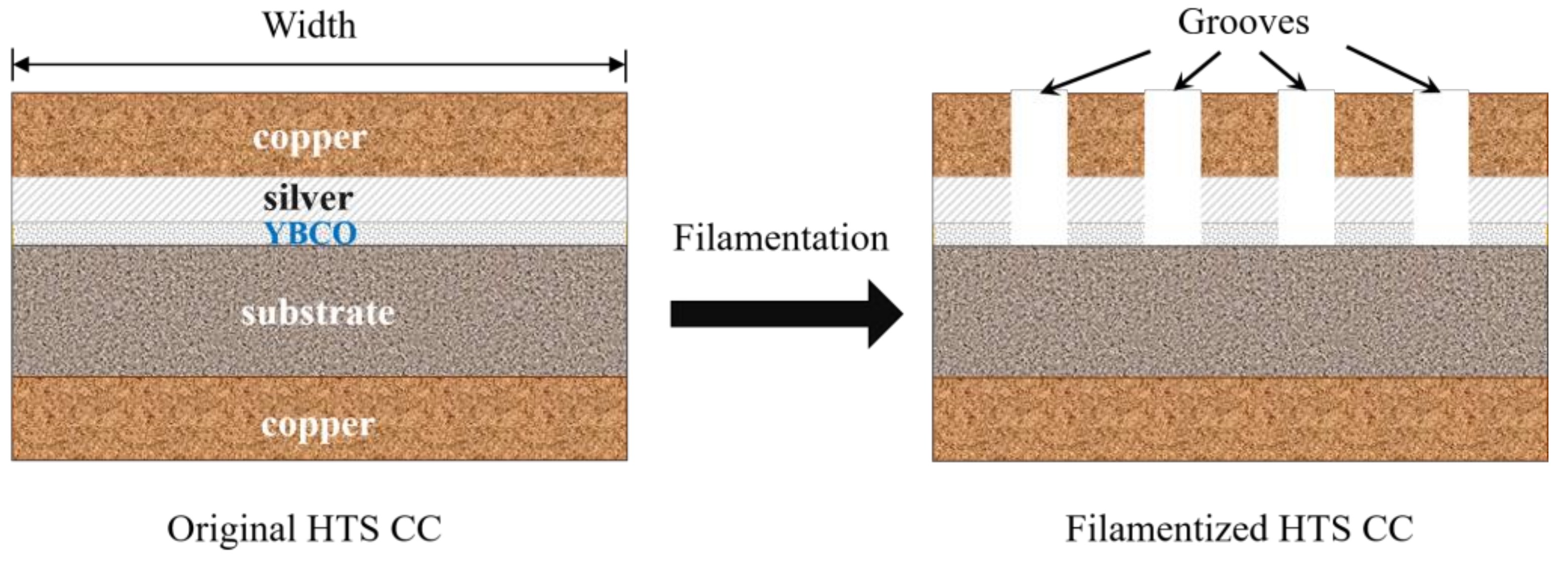
Aerospace electrical machines work at very high speeds (7–50 krpm), and accordingly the adopted HTS materials in superconducting machines ought to be capable of operating in a high-frequency electromagnetic environment (~0.2–2 kHz) [15]. Until now, the vast majority of numerical models are based on the thin film approximation and only the HTS layer is considered, which has been proven inapplicable for high frequencies beyond 100 Hz for the first time by our previous research work [22,23,24]. Therefore, the multilayer physical structure of the commercial HTS CC needs to be taken into account, typically composed of the copper stabilizers, silver overlayer, and substrate, in addition to the HTS layer, as shown in Figure 2b. In [23], Zhang et al. have analyzed the magnetization loss and dynamic loss of HTS CCs, stacks, circular coils as well as racetrack coils over a wide frequency band from 50 Hz to 20 kHz using the H-formulation-based multilayer numerical models. The modelled losses in different layers of the studied 2 × 12 double pancake racetrack coil in [23] are shown in Figure 6. It can be found that the loss in the copper layer increases fast and it will be approaching the magnetization loss and the total AC loss with increasing frequency. Musso et al. have also studied the AC loss distributions in various layers of HTS CCs by use of the AV formulation and found that the contribution to the total losses of the non-superconducting parts is strengthened when the field frequency surpasses 1 kHz [126]. However, the electromagnetic interaction among different layers can largely increase the number of DOF and computational complexity, especially for the 3D modelling of racetrack coils.
(2)
The electromagnetic environment in electrical machines is quite complex, composed of high-frequency harmonics. Therefore, the electromagnetic signals are not purely sinusoidal. The vast majority of numerical models concentrate on the AC loss with standard sinusoidal AC transport current or magnetic fields. Although some simulation work of AC loss has considered both the DC background field, AC ripple field, and non-sinusoidal currents [127,128,129,130], the input signals for simulation are not real synthetic signals generated inside practical electrical machines. Consequently, the performance of HTS CCs under a complex synthetic electromagnetic environment deserves further exploration.
(3)
The magnetic field distribution inside HTS machines is determined by both the superconducting and non-superconducting parts; thus, just modelling the superconductors is not sufficient to reflect the overall power dissipation of the machine that decides the design of cryogenic systems. The non-superconducting parts can contain conventional conductors, iron cores, and permanent magnets; thus, their electromagnetic interaction with the superconductors has to be considered. However, the existing numerical models have rarely considered the influence of non-superconducting parts.
(4)
3D numerical models of superconducting machines are still lacking due to a large number of DOF and high computation complexity. Studies on convergence and computational speed in 3D models have to be thoroughly conducted to improve simulation efficiency.
(5)
Besides the electromagnetic properties, the thermal characteristics of superconductors should also be investigated because they directly affect the design of cryocoolers and quench protection. An electro-thermal numerical model for high-speed superconducting machines needs to be developed.
(6)
The stability of superconducting materials is critical to the normal functioning of the machine. The high centrifugal force in high-speed electrical machines brings a big challenge to the design of rotating field coils. Apart from the necessary mechanical simulation, online monitoring and fault detection methods of HTS machines have not been studied due to the lack of superconducting machine demonstrators.

5. AC Loss Measurement Approaches

There exist three main approaches for measuring the AC loss of superconductors, namely, electric, magnetic, and calorimetric methods [131].

5.1. Electric Method

The electric method is extensively used on account of its fast measurement speed and high sensitivity. The electric method is usually exploited to measure AC transport current loss and magnetization loss, which consists of three types of techniques: the pick-up coil method, lock-in amplifier method, and the combination of the two techniques. Two typical electrical circuits of the pick-up coil method [132] and the lock-in amplifier technique [54] are presented in Figure 7.
The pick-up coil method is often applied to measure the magnetization loss of superconducting samples [133,134,135,136]. The measurement system is usually composed of the AC power supply, AC electromagnet, isolation amplifier, pick-up coil, compensation circuit, compensation coil, cryostat, as well as data acquisition and processing parts, as shown in Figure 7a. The AC power dissipation per unit length (W/m) can be obtained by [137]
P mag = A G f V N μ 0 0 1 f V p k V c B ext d t
where A and V are the sample volume and cross-sectional area surrounded by the main coil, respectively; N refers to the turn number per unit length of the main pick-up coil; Vp and Vc represent separately the induced voltage in the pick-up coil and the compensation coil; k denotes an adjustable coefficient. G is the geometrical correction factor, which has to be calculated for various arrangements of tested samples and pick-up coils.
Yang et al. have derived a general formulation used for the calibration of the pick-up coils with distinct geometries and concluded that the AC loss of round/square wires can always be measured with errors less than 10% using coils of any turn and dimensions [133]. Souc et al. have measured the AC loss and the voltage signals of single pancake coils using different pick-up coils with the help of a transformer and found that the AC loss can be measured through voltage taps on a turn close to the coil average to avoid the difficulties in correcting the huge inductive signal of the whole coil when the number of turns is greater than 10 [134]. Different from the conventional pick-up coil method, a calibration-free method has been proposed by Souc et al. to measure magnetization loss [138]. A coil wound in parallel to the AC field magnet is employed as the measurement coil, and a compensation system is utilized to eliminate the eddy current loss in the coil winding. Consequently, the magnetization loss of the sample of any geometry can be determined by measuring the power supplied by the AC source to the AC magnet without calibration.
The lock-in amplifier technique is usually applied to the measurement of transport current loss of HTS CCs and non-inductive coils [139,140,141,142,143,144,145]. The measurement system usually consists of the AC power supply, non-inductive voltage divider, cryostat, compensation coil, and acquisition system, as shown in Figure 7b.
Time-domain periodical current, i(t), and voltage, u(t), can be expressed in the form of Fourier expansion, as [130]
i ( t ) = i 0 + n = 1 a n sin ( n ω t + φ n )
u ( t ) = u 0 + n = 1 b n sin ( n ω t + ϕ n )
where i0 and u0 are separately the DC components of the current and voltage; an and bn represent the Fourier coefficients; φn and ϕn are phase-related constants. When the transport current is purely sinusoidal, the average power dissipation can be written as
P trans = i 0 u 0 + 1 2 a 1 b 1 sin ( φ 1 ϕ 1 )
It can be seen that, from (21), Ptrans depends on the first harmonics. With the lock-in amplifier technique, the transport power loss per unit length (W/m) of an HTS CC can be written as
P trans = I rms U rms L
where Irms means the root of mean square (RMS) value of the AC transport current carried by the sample CC; Urms is the RMS value of the loss voltage component; L denotes the studied length of the sample.
In [145], Pei et al. have developed a high-precision digital lock-in measurement technique using a lock-in amplifier and nano-voltage meter, and it can resolve signals at the nano-volt level. Different from conventional electric methods, Souc and Gömöry have developed a compact cold-core toroidal transformer system and proposed an auxiliary contactless loop-based electric method to measure the transport current loss of long superconducting samples [146]. This measurement method could be applied to complex structures, e.g., superconducting cables, and help monitor the quality of long pieces of superconducting tapes. To deal with the disadvantages of conventional compensation coils, e.g., low mechanical control precision, narrow compensation range, and voltage with harmonic components, Liao et al. have proposed an automatic compensation method with phase detection and a feedback control algorithm for measuring the AC loss of HTS coils [147]. This method possesses a higher degree of automation and can be potentially applied to different objects in complex environments. In practice, the superconducting elements are normally put inside a metallic containment vessel, in which additional AC loss can be generated due to the induced eddy current. Therefore, Pei et al. have measured the total AC loss of a YBCO coil in different containment vessels using a compensation coil and recommended the vessel with a non-metallic material to minimize the eddy current loss [148]. Shen et al. have recently developed a distinct lock-in amplifier method to measure the transport current loss, with which the unknown inductive part of the obtained voltage can be eliminated by alternating the inductance of the compensating coil, and thus the loss can be calculated without phase control [149]. An electric measurement method without the application of a lock-in amplifier has been recently put forward by Breschi et al. [150]. This approach includes a Hilbert transform-based treatment procedure in terms of the voltage and current signals of the HTS sample, allowing one to analyze the harmonic components of the signals with a remarkable noise reduction. Sytnikov et al. have proposed a digital phase shift method for the AC loss measurement of HTS power cables, which has provided a fast and simple way to estimate the AC loss with an error ± 25%, without the application of expensive lock-in amplifiers [151]. This electric method has recently been adopted in [152] to analyze the performance of a 23 kV/60 MVA class tri-axial HTS power cable for real-grid applications in Korea.
When the superconductor carries AC transport current and is simultaneously exposed to an AC magnetic field of the same phase, the combination of pick-up and lock-in amplifier techniques should be adopted to measure the total loss. Rabbers et al. have proposed an “8” shaped pick-up loop and voltage tap combined measurement method, which can be used to measure separately the transport current loss and magnetization loss of an HTS tape, and the total AC loss has been obtained by summing the two types of losses [153]. In order to measure the total AC loss in HTS CCs carrying AC transport current in an AC transverse magnetic field, Jiang and Amemiya have developed a linked pick-up coil (LPC) to reduce the error in the measured magnetization loss due to the variation of field orientation and used the combination of an internal compensation coil and a non-inductive shunt resistor to reduce the LPC output voltage and phase error [154]. Schwartz et al. have designed a versatile AC loss and stability characterization facility suitable for various temperatures between 35 and 100 K [155]. This facility can be utilized to measure the total AC loss under simultaneous AC transport currents and background fields, and the sample can rotate to change its orientation with respect to the field. Vojenciak et al. have studied the influence of the voltage taps position on the AC loss of the HTS tapes and pointed out that the placement of voltage contacts outside the current leads is beneficial for the protection of the sample against the thermal runaway, but the eddy current loss in normal metal is unavoidable during the loss measurement [156].
The above-mentioned AC loss measurement methods perform well when the carried current is purely sinusoidal. However, as pointed out in Section 3, the superconductors applied to electrical machines have to work with non-sinusoidal signals, namely, harmonics. De Bruyn et al. have specified in [130] that the total AC loss is not always the result of a linear contribution of different harmonics when the transport current is not purely sinusoidal. Therefore, to measure the AC loss in superconducting machines, the conventional electric methods need to be improved. A direct electric method has been proposed in [130], which is achieved by directly measuring the current and voltage over the specimen. Therefore, the average Ptrans can be calculated by
P trans = 1 N T t = t 0 t = t 0 + N T u ( t ) i ( t ) d t
where T is the current cycle, N is an integer. The diagram for the measurement system is shown in Figure 8. Zhu et al. have recently proposed an integral method for measuring the AC loss of HTS coils carrying non-sinusoidal current [157]. The current flowing through the HTS coil is obtained by measuring the voltage of the inductance-free resistor (divider). The proposed integral method has provided a useful tool for measuring the AC loss of superconductors carrying non-sinusoidal currents, which is of great importance for the loss quantification in superconducting machines.
As mentioned above, dynamic loss happens when the HTS CC carrying DC is exposed to time-varying magnetic fields, which can dominate the total loss of field coils in superconducting machines. The experimental setup for the measurement of the dynamic loss of HTS CCs is shown in Figure 9, designed by Jiang et al. [158]. This system is mainly composed of a custom-built AC magnet, a DC power supply that provides transport current, and a cryogenic container to maintain the operating temperature. The dynamic loss is calculated by measuring the voltage along with the transport current of the coated conductor sample. The measurement method has been extensively applied to much experimental exploration of dynamic loss and dynamic resistance of HTS CCs [16,63,64,158,159,160,161]. Ogawa has studied the magnetization loss and dynamic loss of an HTS pancake coil with a double pick-up coil method and found that the dynamic resistance can mitigate the DC of the coil when it is operated in the permanent current mode [135].

5.2. Magnetic Method

The magnetic method is regularly used to measure the hysteresis loss of superconductors. By measuring the voltages over pick-up coils around the superconducting specimen, which are then multiplied by the field strength and integrated over one cycle, the variation in the magnetic moment of the specimen can be identified [162]. The magnetic moment of the superconductor can be obtained with different methods, such as pick-up coils, Hall probes, superconducting quantum interference devices (SQUID), and vibrating-sample magnetometers (VSM). The measurement system is usually composed of the AC magnet, cryostat, pick-up coil, high-current amplifier, compensation coil, as well as the data acquisition system.
According to [131], for small superconducting samples, the hysteresis loop can be measured by SQUID and VSM methods to obtain the hysteresis power loss per unit length (W/m), as
P hys = C A f μ 0 H ext d M = C A f μ 0 M d H ext
where A is the geometrical cross-sectional area of the sample, C denotes the effective area coefficient (C = 1 at low frequencies), Hext stands for the external AC field strength, and M represents the measured magnetization. Hysteresis loss can also be acquired through the measurement of the imaginary part of complex AC susceptibility. In a superconducting machine, the HTS field windings are always exposed to a large DC background field with a relatively small AC ripple field. In this case, Phys can be calculated by
P hys = C A f π B m 2 μ 0 χ
where χ″ is the measured imaginary part of the AC susceptibility, and Bm is the amplitude of the AC magnetic field. The minimum measurable loss value can attain 10−6~10−5 W/m with the magnetic method. The equivalent circuit for a typical AC susceptibility measurement system is shown in Figure 10.
Pardo et al. have measured the voltage signal and AC loss in a pancake coil made of CCs with the ferromagnetic substrate utilizing a SQUID magnetometer at 100 K [164]. However, it appears that the SQUID and VSM techniques are too slow for measurement at power frequencies. For varying magnetic fields with different orientations, the pick-up magnetic methods seem to be the best choice. Gömöry has measured the AC susceptibility with a pick-up coil and lock-in amplifier combined method [165]. Kajikawa et al. have proposed a perpendicular-field loss measurement method for superconducting coils using a pair of pick-up coils, which enables the measurement of long-length samples in a compact apparatus [166]. Iwakuma et al. have applied a saddle-shaped pick-up coil to measure the magnetization loss of superconducting tapes and windings because it can avoid the end effect by using longer sample wires [167,168,169]. The saddle-shaped pick-up coil-based magnetic method has recently been used in [170] to quantify the AC loss of perpendicularly stacked REBCO CCs. To characterize the AC loss of a coil wound cable-in-conduit conductor (CICC) in pulsed regimes, Muzzi et al. have modified the pick-up coils with an extra-compensation procedure [171]. Fisher et al. have developed a simple calibration-free method based on the dipole approximation, which allows for obtaining both the AC loss and orientation of the sample magnetic moment [172]. More recent experimental measurement work based on the magnetic method can be found in [173,174].

5.3. Calorimetric Method

If the superconducting sample carrying an AC current experiences an AC magnetic field, the conventional electric method will be applicable for the AC loss measurement only when the current and field are varying at the same frequency and in phase. It is practical to have the transport current and magnetic field out of phase in superconducting machines. In this case, the calorimetric method becomes a superior alternative. In [175,176], the influence of the phase shift between the external magnetic field and the transport current on the AC loss of the HTS tape has been investigated using both the electric method and calorimetric method. As a comparison, though the electric method has higher sensitivity, the calorimetric method can provide higher reliability. Besides, the disturbance of alternating magnetic fields or currents is intrinsic in the electric and magnetic measurement approaches, which is not a concern for the calorimetric method. Therefore, the calorimetric method can be applied to a complicated electromagnetic environment. With the calorimetric method, the total AC loss can be obtained by the measurement of either the temperature rises of superconductors or the evaporated cryogen.

5.3.1. Measurement of the Temperature Rise

The thermal conductivity measurement technique was first put forward by McConnell and Critchlow for the determination of superconducting AC power loss [177]. To measure the temperature variation, cryogenic thermometers, cryostat, thermal isolation material, and voltage taps are usually needed. The calibration of the thermometers is the first step. Then, the variation of the thermal conductivity of the superconducting sample with temperature needs to be measured. Once the temperature distribution along the sample is known, the total AC power dissipation can be obtained by [177]
P AC = 8 K A Δ T L 2
where K, A, and L represent the thermal conductivity, cross-sectional area and length of the superconducting sample, respectively. ∆T denotes the temperature difference between the sample center and its ends. It is claimed that the thermal conductivity measurement technique is possibly able to measure a loss of 2 × 10⁻¹⁰ W/cm with an uncertainty of about 30% [177].
In order to measure the low losses of superconductors operated at liquid-helium temperature calorimetrically, Schmidt and Specht have developed a temperature-rise-measurement-based method with a resolution of 10−8 W [178]. The superconducting sample is placed into a vacuum vessel and connected via a thermal resistance to the liquid-helium bath. However, to measure low loss of less than 1 μW, three conditions must be fulfilled: no additional eddy current losses generated in the structure, limited self-heating power in the thermometer attached to the sample, and stable temperature of the heat sink. Dolez et al. have proposed a null calorimetric method for measuring the AC loss of superconducting tapes without any compensation and any size and shape restriction [179], and then this method has been ameliorated in [180] to overcome the insufficient thermalization of the tape extremities and thermocouple reference junctions. Although it was demonstrated in [179,180] that the proposed null calorimetric method was able to measure losses of 10−8 W/cm, its accuracy and uncertainty were not discussed in detail. To simplify the experimental setup and save measurement time, Ashworth and Suenaga have reported a simple technique to measure the AC losses using a differential thermocouple [181]. However, this technique has a low resolution limit of approximately 0.01 W/m. See et al. have reported a calorimetric method to determine the AC losses of superconducting samples in superimposed DC and AC fields/currents by measuring the change in resistance due to temperature variation [182,183]. The measurement system can achieve operating temperature from 2 to 300 K [183].
For the superconductors located in electrical machines, they can experience rotating magnetic fields. In view of this situation, Ghoshal et al. have adopted the calorimetric method based on the temperature variation of the superconductor thermally insulated from the cooling bath [184]. The principle of this calorimetric method is shown in Figure 11, in which the tested specimen is placed in a vacuum vessel and connected to the coolant by thermal resistance. The NASA Glenn Research Center has recently developed a LH2-based test rig, which can be used to measure the AC loss of HTS stator coils in rotating magnetic fields with the thermocouples between the range of 18 to 28 K (extensible to 95 K employing LN2 or GHe as a coolant) [185]. The system can be applied with the following test parameters: injected current (0 to 400 A), magnetic field (0 to 0.6 T), phase angle between injected current and induced voltage (−180° to 180°), and frequency (0 to 400 Hz).
Another temperature variation detection method is by optical fiber Bragg grating (FBG) [186], which takes advantage of the wavelength variance dependence of temperature described by
Δ λ B = α T Δ T = λ B ξ + α Δ T
where λB stands for the wavelength of the optical FBG; αT denotes the temperature-dependent sensitivity coefficient; ξ and α represent temperature-dependent constants. The minimum measurable loss by the temperature rise measurement method is approximately 10−4 W/m. The measurement system using FBG is presented in Figure 12. Compared to the conventional calorimetric methods, the FBG sensor possesses the advantages of anti-electromagnetic interference and rapid response; it is thus capable of measuring the AC loss of HTS applications in a complex electromagnetic environment at a faster speed.

5.3.2. Measurement of the Cryogen Evaporation

The temperature rise due to dissipated energy will lead to the evaporation of the cryogen; thus, the measurement of AC loss can be achieved by measuring the gas flow volume of the evaporating cryogen, namely, the boil-off method [187]. The corresponding measurement system is mainly composed of the AC power supply, non-metal cryostat, cryogen, heat exchanger, thermostat, and gas flow meter. The AC power loss per unit length (W/m) can be obtained by [131]
P AC = C A f T b T m γ C ( T ) d T = C A f H ( T m ) H ( T b )
where A is the geometrical cross-sectional area of the sample; C stands for the effective area coefficient; Tb is the environment temperature; Tm denotes the average temperature rise; γC(T) is the volumetric heat capacity of the superconductor; H(T) refers to the enthalpy of the cryogen at temperature T. It should be noted that the measurement of cryogen evaporation is time consuming and does not possess a high accuracy, with the minimum measurable loss of 10−4~10−2 W/m. With this method, Kuroda has measured the AC losses of superconducting solenoidal coils with a resolution of 10−3 W [188]. However, it is difficult to maintain the thermal equilibrium of the liquid-cryogen-filled cryostat, which affects the measurement accuracy. To overcome this disadvantage, Kuroda has then proposed a modified boil-off method without a pre-calibration, and the AC loss is obtained by multiplying the generating rate of the helium gas by a constant [189]. After improvement, the accuracy and measurement range could attain ± 3% and 3–170 mW, respectively. Okamoto et al. have developed an apparatus for applying the nitrogen boil-off method to measure the AC losses in HTS coils at liquid nitrogen temperature, and a sensitivity of about 0.1 W was achieved [190]. W. Yuan et al. have measured the transport current loss of a pancake coil with the LN2 boil-off measurement technique and the electric method, respectively. The experimental results are consistent with the model calculations, though there exists a discrepancy between the modelling results and the electric-method-based experimental data at large currents [191]. Figure 13a shows a calorimetric system to measure the total AC loss of superconducting tapes or coils based on the boil-off of liquid nitrogen, proposed by Murphy et al. [192]. With the help of the proposed calorimeter system, a permanent magnet rotor has been designed to simulate the electromagnetic environment of an electrical machine, and the AC loss of one armature coil carrying AC current exposed to rotating fields has been measured, as shown in Figure 13b. The calorimetric system can measure low losses from a few milliwatts to several hundred milliwatts [192].
The comparison among three different measurement methods has been summarized in Table 4. Nowadays, the measurement of AC loss has been concentrated on simple single HTS tape or stacks of tapes [153,154,193,194,195], and stationary coils [196,197,198,199,200,201]. It can be seen that the most widely adopted method is the electric method. Nevertheless, it should be noted that most of the experimental measurements are conducted with pure sinusoidal currents or fields (or both in phase at the same frequency). As far as the AC loss measurement in high-speed electric machines is concerned, the extensively used traditional electric method is inapplicable for measurement in a high-frequency electromagnetic environment containing harmonics. Significant progress has been made in [202] in which Zhang et al. have measured the AC loss of HTS stator coils under rotational magnetic fields inside an axial flux type machine demonstrator. However, for simplification, the tested unit is one circular coil rather than widely used racetrack coils, and the measurement has been conducted under low frequencies of less than 150 Hz. Therefore, for the measurement of AC loss in a high-speed superconducting machine, an efficient and highly accurate method remains to be developed.

6. AC Loss Reduction Techniques

6.1. Filamentation of HTS CCs

The large cross-sectional aspect ratio of HTS CCs leads to a high magnetization loss. Therefore, to reduce AC loss, the striation of the HTS layer to a filamentary structure has been proposed [203,204,205,206,207]. Two types of techniques can be used to divide the HTS layer: striation before or after REBCO synthesis [206,207]. The former is the processing of the substrate by etching, lift-off, mechanical scribing, and ink-jet printing for the synthesis of the striated HTS layer or the barrier between filaments. The latter includes laser ablation, mechanical cutting, and chemical etching, etc. Godfrin et al. have made a comparison of the two striation techniques in [207]. The diagram of the filamentation of a typical HTS CC is presented in Figure 14.
As illustrated in Figure 1, the filamentation of HTS CCs can effectively decrease the AC loss, and the loss reduction effect gets enhanced with the increasing number of filaments. According to Equation (1), the magnetization loss is proportional to the square of the width of the HTS CC; thus, a reduction by a factor N is expected if the HTS layer is striated to N filaments. However, this is true only at sufficiently high fields because at lower fields the superconductor volume penetrated by the field is larger in uncoupled filaments than in a nonstriated CC [20] and hence the loss of a filamentized CC can be greater than that of the original one, as shown in Figure 1. The influence of subdividing YBCO films into arrays of parallel strips on AC loss was revealed experimentally for the first time in [208]. Then, in [209], it has been shown that the laser striation process has little influence on the critical current of the tape with a small number of filaments. However, when increasing the number of filaments, as illustrated in [207], the critical current of each CC will experience a degradation. In [210], the authors point out that an AC loss decrease proportional to the number of filaments only happens when the filaments in perpendicular magnetic fields are decoupled. However, this is not the case in practical machine applications because the filaments are coupled by current leads. The coupling loss between filaments can largely increase the total AC loss, which is proportional to the frequency and the square of the external magnetic field [203]. As illustrated in [203], a decrease in coupling loss at high frequencies can be achieved by increasing the transverse resistivity and by reducing the twist pitch. It should be noted that though the filamentation of the CC can help decrease the overall AC loss, the mechanical strength of each filament degrades. Therefore, once one filament breaks down due to a localized defect, hotspot, or a mechanical shock, the superconducting state of the CC can be destroyed. To solve this problem, bridges can be exploited to enhance the connectivity between filaments. In [211], AC losses of striated and nonstriated RABiTS CCs were measured and compared. The results showed that the application of bridges can increase the total AC loss due to significant filament coupling; however, the total AC loss was still much lower than that of CCs without filamentation. Therefore, the number and arrangement of filaments can bring about a trade-off between the current sharing capacity and total AC loss of HTS CCs. It is not sufficiently effective to decrease AC loss simply by cutting the CC into filaments because of the incomplete flux penetration between the filaments [212]. Therefore, virtual transverse crosscuts have been proposed in [213] to introduce flux penetration between the filaments more uniformly, which can help magnetically decouple the filaments and further reduce AC loss. Indium bridges across crosscuts can be used to guarantee the continuity of the current flow. The improvement of striation methods can also help with the reduction of AC loss. A significant loss reduction method in HTS CCs with transposed filaments has been reported in [214]. The proposed CC is made of two diffusively reinforced silver-clad CCs with filaments in a zigzag form which are partially isolated by a dielectric layer. In [214], the authors demonstrate that the improvement of the bonding process and the decrease in the filament size contribute positively to the AC loss reduction. In [215], a scalable laser lithographic process has been applied, including laser patterning a resist coating, and etching. The results have demonstrated that the critical current is not debased for striation width over 150 μm, and the AC loss can be decreased effectively. Different from conventional filamentary HTS CCs, a soldered-stacked-square (3S) wire has been proposed in [216]. The fundamental manufacturing process is to divide HTS CCs into 1-mm-wide ones, solder with a soldering furnace, and put them into a stack, as shown in Figure 15. In [216], the authors reported that the 3S concept can help to decrease AC loss by 80% compared with originally uncut tapes.

6.2. Roebel, Rutherford-Type, and CORC® Cables

Another method to reduce the AC loss of HTS CCs is to change their physical arrangements, e.g., the Roebel concept [217,218,219], Rutherford cable [220,221], and Conductor on Round Core (CORC®) wire [222,223,224]. The Roebel cable concept was proposed by Ludwig Roebel in 1914 to produce a low-loss copper cable [224]. The first HTS Roebel cable was developed by the Siemens Corporate Technology group using BSCCO-2223 tapes in 2004 [217], and later the Karlsruhe Institute of Technology applied the Roebel structure to REBCO CCs in 2006 [218]. The diagram of a typical Roebel cable [225] is shown in Figure 16a, in which the HTS CCs are cut in a specially designed zigzag pattern. Because of their periodically repeating and transposed physical properties, Roebel cables can effectively reduce the transport current loss and magnetization loss compared with conventional HTS stacks, especially at medium-high currents and low magnetic fields [218]. The authors of [219] have shown that the decrease in strand width can further help lower AC loss. As mentioned before, the filamentation of HTS CCs can help with the reduction of AC loss. However, at high frequencies, the coupling loss between filaments will increase rapidly and begin to dominate. To minimize the high-frequency coupling loss, the Rutherford cable structure has been proposed by Wilson, which does not require complex twist geometries [220]. It has been demonstrated that the Rutherford configuration is a promising candidate to realize the ultimate low AC loss [221]. The conventional Rutherford-type cabling technique is suitable for round strands of superconductors [226], e.g., BSCCO-2212 and NbTi wires, as shown in Figure 16b. To extend the Rutherford-type design towards 2G flat HTS CCs, the concept of twisting stacked tapes has been firstly introduced by Takayasu et al. [227], based on which Uglietti et al. have developed a novel flat HTS cable by winding the HTS strands around a central copper former [228,229], as shown in Figure 16c. Although the design of the twisted flat HTS cables was proposed for fusion magnets with high current-carrying capacity, they are believed to possess the potential to be applied as superconducting machine windings to achieve low AC loss. The CORC® cabling approach was initiated by Van der Laan et al. [222], which is achieved by the helical winding of REBCO CCs on a round former, as shown in Figure 16d. The decrease in the width and thickness of commercial REBCO CCs has enabled the production of flexible, round, and multifilamentary HTS wires [223]. Vojenčiak et al. have demonstrated that the magnetization loss in CORC® cables twisted from striated CCs holding five filaments can be reduced by a factor of almost 5 at fields higher than the penetration field [230]. Terzioglu et al. have concluded that the copper tube former can contribute to the transport current loss and magnetization loss of CORC® cables; thus, an optimized former material with high thermal conductivity and low electrical conductivity should be employed to reduce the AC loss [231]. Yagotintsev et al. have compared the AC loss and inter-tape contact resistance of multiple cabling methods, including REBCO CORC®, Roebel, and stacked tape cables [232]. It is found that the CORC® cable has lower hysteresis loss in an alternating magnetic field perpendicular to the wide side of the REBCO layer, compared with Roebel cables and non-twisted conductors. Nevertheless, it should be noted that the twisting of filaments has the possibility of damaging the microstructure and grain orientations; thus, the critical current of the CC can be severely affected.

6.3. Flux Diverters

In addition to the modifications to the physical structure of HTS CCs, the application of magnetic materials as flux diverters in electrical machines can also serve to decrease the AC loss of superconductors. In [233,234], Gömöry has demonstrated that adding ferromagnetic covers on the edges of a single HTS CC or a stack of tapes can effectively reduce the magnetization loss. However, the reduction effect becomes weaker with the increase in CC numbers. The ferromagnetic shielding effect in HTS CCs was first experimentally observed in [235] and the ferromagnetic materials’ potential of loss reduction has been evaluated. As pointed out in [235], an ideal flux diverter material should exhibit low saturation field densities, low hysteresis loss, and high permeability. A YBCO pancake coil with two ring-shaped magnetic diverters made of an iron-based amorphous alloy has been tested in [236], and the results have shown that the reduction of AC loss is due to the magnetic mirror effect rather than change of the coil critical current. However, Pardo has pointed out that the hysteresis loss in the magnetic materials can degrade the reduction effect of flux diverters. The influence of flux diverters on the reduction of transport current loss has been verified in [237], and it is shown that the favored diverter material should possess both a low remanence and a high saturation field. Liu has studied the geometric dimension and location optimization of the magnetic flux diverter for a better loss reduction effect [238,239,240]. The results in [238] have shown that the flux diverter demonstrates an adverse consequence on the CC critical current, depending on the width, height of the diverter, and the gap between the diverter and the HTS coils. In [239], the authors show that, besides the positions of flux diverters, their loss reduction effect is also related to the load ratio between the transport current and critical current, e.g., the use of flux diverters in the middle and end positions of the double pancake coil can reduce the AC loss by 70%. The frequency dependence of the diverter effect for the transport current loss of a YBCO coil has been studied within the frequency band of 10 Hz~5 kHz in [240], and the arrangement of the HTS coil and flux diverters are presented in Figure 17. Interestingly, the effect of flux diverters for HTS coils with magnetic substrate depends on both the load ratio and frequency: at low load ratios and high frequencies, the flux diverter will increase the total loss, because under such conditions the eddy current loss and ferromagnetic loss (in both diverter and the magnetic substrate) will be enhanced. However, the effectiveness of flux diverters for non-magnetic-substrate-based HTS coils at high frequencies still deserves further investigation in the future.

6.4. Winding Techniques

Apart from the structure modification of superconductors and the application of ferromagnetic flux diverters, winding techniques are another effective way to decrease the AC losses of coils. Kawagoe et al. have proposed a winding method for multilayer-type conductors composed of stacked Rutherford-type cables by controlling the twist angle around the conductor axis, which can help decrease the total AC loss by 74% compared to the conventional winding method [241]. Heydari et al. have applied two auxiliary windings to reduce the leakage flux in HTS transformers so that the AC loss of HTS coils can be decreased by about 13.6% [242]. Kim et al. have employed a metal-clad (MC) winding technique for non-insulated (NI) HTS coils to enhance the turn-to-turn resistance by adding a 5-μm-thick coating of stainless steel to a copper-stabilized HTS CC [243]. It has been demonstrated that the NI coil has the least AC loss, followed by the NI coil with the MC winding technique, and the insulated coil has the highest AC loss. However, it should be noted that the AC transport current loss tests in [243] were performed at 20 Hz, i.e., at low frequencies. Therefore, the effectiveness of the added metal clad in a high-frequency electromagnetic environment (e.g., in high-speed rotating machines) remains unclear. In addition, the application of such metal can definitely increase the total mass of the machine windings. The influence of turn-to-turn resistivity on the AC loss of HTS coils has been recently discussed by Wang et al. in [244], in which a grading turn-to-turn resistivity technique has been put forward to reduce the total AC loss on the outer turns while keeping good thermal stability on the middle turns of the NI HTS coils used for electrical aircraft propulsion. Simpson et al. have invented a shaped profile winding for minimal AC loss in conventional electrical machines [245], as shown in Figure 18, which maximizes slot area utilization to realize an improved low-speed and DC performance while achieving low AC loss. As pointed out by Simpson and Kails from the University of Bristol, the proposed shaped profile winding technique can have the potential to be adapted to superconducting windings in the future. Recently, Jiang et al. have reported a 15% loss reduction in a 3-phase 1 MVA HTS transformer by exploiting the anisotropic field dependence of the critical current of HTS CCs [246]. By orienting the CC or coil appropriately with respect to the external field, a substantial AC loss reduction can be achieved.
To sum up, the existing AC loss reduction methods have provided some significant design guidelines, but a few challenges remain:
(1)
The filamentation of HTS CCs, the Roebel, the Rutherford as well as the CORC cables can help with the reduction of AC loss. However, their electro-thermal performance under the skin effect and coupling effect between filaments in the practical machine environment (especially at high frequencies for high-speed rotating machines) is still unclear; therefore, their loss reduction effectiveness needs to be further explored.
(2)
Flux diverters have been proven to be useful to decrease the AC loss of superconductors, but this effectiveness gets weaker with the increase in the number of turns in a coil. Besides, the hysteresis loss in ferromagnetic flux diverters increases rapidly with increasing frequency. In this way, the flux diverter at high frequencies can become a severe heat load itself. Therefore, the contribution of flux diverters to the total loss distribution at high frequencies inside superconducting machines needs more investigation.
(3)
Winding techniques appear to be a useful alternative for the AC loss reduction of HTS coils. When the coils are implemented into rotating machines, besides the electromagnetic performance, their mechanical strength, thermal characteristics, as well as processing difficulty also need to be considered. A balance needs to be reached between the AC loss reduction and total mass augmentation for the design of superconducting machines.

7. Conclusions and Future Outlook

This paper has reviewed multiple AC loss-related topics with respect to superconducting machines: adopted superconducting materials, AC loss mechanism and analytical formulae, modelling methods, measurement approaches, as well as loss reduction techniques. The main conclusions are presented as follows.
The primary advantage of LTSs lies in their relatively lower cost. MgB2 has been employed in many armature coils because of its filamentary structure which can achieve a relatively lower AC loss. HTS CCs, fabricated from REBCO or BSCCO, possess a larger current-carrying capacity and higher critical field; thus, they can bring a higher electric and magnetic load to superconducting machines. Although the cryogenic system for superconductors has not been discussed in this paper, we have to note that its cost plays an important role in the design of superconducting machines. Compared to LTSs and MgB2, both of which usually function in LHe at ~4 K or LH2 at ~20 K, HTS tapes have a higher critical temperature; thus, they can be cooled by LN2 operating at 77 K. Therefore, the cost of the cryogenic system used for HTS CCs can be relatively lower. In addition, the material cost of HTS CCs is expected to decrease soon with the advancement of processing techniques and material science. Hence, HTS CCs are believed to have a good application prospect in superconducting machines. HTS bulks and trapped field magnets are also competent candidates as field sources in superconducting machines, which can avoid the application of current leads during operation.
The existing analytical equations to calculate AC loss are mainly focused on HTS thin films. The analytical formulae can help easily understand the loss mechanism and its influential factors, which are conveniently used to predict the AC loss of HTS CCs in simple structures. However, when the HTS CCs are wound into complex structures, e.g., racetrack coils widely used in electrical machines, we need to apply numerical modelling or measurement methods to quantify the total loss. The two principal reasons are: (1) the analytical formulae have been derived based on some necessary approximations and assumptions, which become inapplicable in a complex machine environment; (2) there always exist harmonics in electrical machines composed of high-frequency components, and the interactions between the superconducting and non-superconducting layers of HTS CCs at high frequencies cannot be correctly reflected by the existing equations. Therefore, it remains an open subject for researchers to develop analytical models to predict the AC loss of complex geometries employed in a complicated electromagnetic environment.
The widely adopted numerical modelling methods for the AC loss quantification of superconductors are mainly comprised of: (1) Maxwell’s equations-based FEM achieved by four types of basic formulations, including the T-ϕ formulation, A-V formulation, E-formulation, and H-formulation and their several combinations, e.g., the H-A formulation, T-A formulation, and H-ϕ formulation; (2) the integral equation method for thin tapes solved with FEM; (3) the Minimum Magnetic Energy Variation method; (4) the Minimum Electro-Magnetic Entropy Production method. Maxwell’s equations-based FEM can be easily incorporated into commercially available software, e.g., COMSOL Multiphysics and Ansys, and the interactions between superconducting and non-superconducting parts inside machines can be considered; thus, this approach is recommended for the AC loss estimation in HTS machines. Given that a great number of HTS CCs are needed in electrical machines, the modelling of superconducting windings can be computationally complicated and time consuming. To improve the computational efficiency, three simplification techniques can be exploited, including the homogenization, multi-scaling, and densification methods. For modelling a large number of HTS turns at low frequencies, both the H-formulation and T-A formulation-based homogenization methods have a high computational speed with acceptable accuracy. The application of the multiscale modelling method can largely reduce the number of DOF, requiring less calculation memory, and thus it can further save computational time. The densification method leads to fewer tapes to be modelled. However, the 3D modelling of HTS racetrack coils considering the multilayer structure of each HTS CC in rotating electrical machines remains a big challenge to overcome.
Besides numerical modelling, significant contributions have been realized in the instrumentation and measurement of AC loss in superconductors. More specifically, AC loss measurement techniques can be categorized into the electric method, the magnetic method, and the calorimetric method. The electric method has been most widely used because of its relatively higher sensitivity and shorter measurement duration. For measuring the total AC loss composed of transport current loss and magnetization loss, the electric method and calorimetric method are suggested. Considering the complex electromagnetic environment composed of high-frequency harmonics inside electrical machines, the calorimetric method seems to be the best choice because it disregards the object shape and working conditions, being also able to measure large-scale specimen. However, the sensitivity of the calorimetric method is relatively poorer, and it takes longer for measuring compared to the electric and magnetic methods. The conventional electric method has been improved to measure the AC loss of superconducting coils carrying non-sinusoidal currents or in the case of phase shift between the measurement voltage and transport current, which is of great significance for the loss quantification in electrical machines. Nevertheless, an efficient and accurate experimental method remains to be developed to measure the total AC loss of superconductors applied in a complicated electromagnetic environment with harmonics inside practical electrical machines.
Concerning the AC loss reduction techniques, the modification of superconductor structures has been widely investigated, e.g., the filamentation of HTS CCs, the 3S wire, the Roebel structure, the Rutherford concept, as well as the CORC® wire. However, it should be pointed out that the filamentation process can potentially weaken the mechanical strength and critical current of the HTS CC. Although the filamentary structure can help with the reduction of AC loss at low frequencies, e.g., Roebel cables, it can bring about a high coupling loss between different filaments at high frequencies. The Rutherford design can mitigate the coupling loss, but the twisting of filaments has the possibility of damaging the microstructure and grain orientations; thus, the critical current of the CC can be severely affected. The tube former can contribute to the AC loss of CORC® cables; thus, an optimized former material with high thermal conductivity and low electrical conductivity needs to be investigated. Ferromagnetic flux diverters have been demonstrated to be useful for decreasing the AC loss of superconductors, despite that the effectiveness drops with the increase in turn numbers. We need to realize that the ferromagnetic materials can favor the total power dissipation of electrical machines; thus, the effect of flux diverters applied to high-speed rotating machines deserves further exploration. Winding techniques can also be exploited to achieve the AC loss reduction of superconducting coils, e.g., the NI HTS coils and shaped profile windings. However, the mechanical and thermal characteristics of superconducting coils should also be taken into account when they are applied to practical electrical machines.
Evidently, remarkable original contributions have pushed forward the area of AC loss analysis, modelling, measurement, and controlling in superconductors. This paper has demonstrated the state of the art in this research area and provided a useful reference for loss quantification and loss reduction techniques in superconducting machines. Additionally, this paper exposes gaps in our understanding and knowledge and opens up the challenges that need to be addressed for the design of high-speed superconducting machines, delivering a helpful guideline for future research efforts.

Author Contributions

Conceptualization, H.Z., F.G. and M.M.; methodology, H.Z., Z.W. and F.G.; software, H.Z.; validation, H.Z., F.G. and M.M.; formal analysis, H.Z., F.G. and M.M.; investigation, H.Z. and Z.W.; resources, F.G. and M.M.; data curation, H.Z., F.G. and Z.W.; writing—original draft preparation, H.Z. and Z.W.; writing—review and editing, F.G., K.G. and M.M.; visualization, H.Z., F.G., K.G. and M.M.; supervision, M.M.; project administration, M.M.; funding acquisition, M.M. All authors have read and agreed to the published version of the manuscript.

Funding

This work was supported by the joint scholarship from the University of Edinburgh and China Scholarship Council (CSC) under Grant (2018) 3101.

Institutional Review Board Statement

Not applicable.

Informed Consent Statement

Not applicable.

Data Availability Statement

The data presented in this study are openly available in [20,21,33,34,35,36,37,38,39,40,41,42,43,44,83].

Conflicts of Interest

The authors declare no conflict of interest.

References

  1. Lei, G.; Zhu, J.; Guo, Y.; Liu, C.; Ma, B. A Review of Design Optimization Methods for Electrical Machines. Energies 2017, 10, 1962. [Google Scholar] [CrossRef] [Green Version]
  2. Wildi, T. Electrical Machines Drives and Power Systems; Prentice-Hall: Englewood Cliffs, NJ, USA, 2005. [Google Scholar]
  3. Saidur, R. A review on electrical motors energy use and energy savings. Renew. Sustain. Energy Rev. 2010, 14, 877–898. [Google Scholar] [CrossRef]
  4. Hossain, M.S. Panel estimation for CO2 emissions, energy consumption, economic growth, trade openness and urbaniza-tion of newly industrialized countries. Energy Policy 2011, 39, 6991–6999. [Google Scholar] [CrossRef]
  5. Cheng, M.; Sun, L.; Buja, G.; Song, L. Advanced Electrical Machines and Machine-Based Systems for Electric and Hybrid Vehicles. Energies 2015, 8, 9541–9564. [Google Scholar] [CrossRef] [Green Version]
  6. Cheng, M.; Zhu, Y. The state of the art of wind energy conversion systems and technologies: A review. Energy Convers. Manag. 2014, 88, 332–347. [Google Scholar] [CrossRef]
  7. Wrobel, R.; Mecrow, B.C. A Comprehensive Review of Additive Manufacturing in Construction of Electrical Machines. IEEE Trans. Energy Convers. 2020, 35, 1054–1064. [Google Scholar] [CrossRef] [Green Version]
  8. Li, S.; Zhang, S.; Habetler, T.G.; Harley, R.G. Modeling, Design Optimization, and Applications of Switched Reluctance Machines—A Review. IEEE Trans. Ind. Appl. 2019, 55, 2660–2681. [Google Scholar] [CrossRef]
  9. Lee, D.; Park, G.; Son, B.K.; Jung, H. Efficiency improvement of IPMSG in the electric power generating system of a range-extended electric vehicle. IET Electr. Power Appl. 2019, 13, 943–950. [Google Scholar] [CrossRef]
  10. Sun, X.; Shi, Z.; Lei, G.; Guo, Y.; Zhu, J. Analysis and Design Optimization of a Permanent Magnet Synchronous Motor for a Campus Patrol Electric Vehicle. IEEE Trans. Veh. Technol. 2019, 68, 10535–10544. [Google Scholar] [CrossRef]
  11. Sahoo, S.; Zhao, X.; Kyprianidis, K. A Review of Concepts, Benefits, and Challenges for Future Electrical Propulsion-Based Aircraft. Aerospace 2020, 7, 44. [Google Scholar] [CrossRef] [Green Version]
  12. Jlassi, I.; Cardoso, A.J.M. Fault-Tolerant Back-to-Back Converter for Direct-Drive PMSG Wind Turbines Using Direct Torque and Power Control Techniques. IEEE Trans. Power Electron. 2019, 34, 11215–11227. [Google Scholar] [CrossRef]
  13. Taherian-Fard, E.; Sahebi, R.; Niknam, T.; Izadian, A.; Shasadeghi, M. Wind Turbine Drivetrain Technologies. IEEE Trans. Ind. Appl. 2020, 56, 1729–1741. [Google Scholar] [CrossRef]
  14. Grilli, F.; Benkel, T.; H¨anisch, J.; Lao, M.; Reis, T.; Berberich, E.; Wolfst¨adter, S.; Schneider, C.; Miller, P.; Palmer, C.; et al. Superconducting motors for aircraft propulsion: The Advanced Superconducting Motor Experimental Demonstrator project. J. Phys. Conf. Ser. 2020, 1590, 012051. [Google Scholar] [CrossRef]
  15. Haran, K.S.; Kalsi, S.; Arndt, T.; Karmaker, H.; Badcock, R.; Buckley, B.; Haugan, T.; Izumi, M.; Loder, D.; Bray, J.W.; et al. High power density superconducting rotating machines—development status and technology roadmap. Supercond. Sci. Technol. 2017, 30, 123002. [Google Scholar] [CrossRef]
  16. Ainslie, M.D.; Bumby, C.W.; Jiang, Z.; Toyomoto, R.; Amemiya, N. Numerical modelling of dynamic resistance in high-temperature superconducting coated-conductor wires. Supercond. Sci. Technol. 2018, 31, 074003. [Google Scholar] [CrossRef]
  17. Feddersen, M.; Haran, K.S.; Berg, F. AC Loss Analysis of MgB2-Based Fully Superconducting Machines. IOP Conf. Ser. Mater. Sci. Eng. 2017, 279, 012026. [Google Scholar] [CrossRef] [Green Version]
  18. Fair, R.; Lewis, C.; Eugene, J.; Ingles, M. Development of an HTS hydroelectric power generator for the hirschaid power station. J. Phys. Conf. Ser. 2010, 234, 032008. [Google Scholar] [CrossRef]
  19. Corduan, M.; Boll, M.; Bause, R.; Oomen, M.P.; Filipenko, M.; Noe, M. Topology Comparison of Superconducting AC Machines for Hybrid Electric Aircraft. IEEE Trans. Appl. Supercond. 2020, 30, 1–10. [Google Scholar] [CrossRef] [Green Version]
  20. Demencik, E.; Vojenciak, M.; Kario, A.; Nast, R.; Jung, A.; Goldacker, W.; Grilli, F. AC Loss and Coupling Currents in YBCO Coated Conductors With Varying Number of Filaments. IEEE Trans. Appl. Supercond. 2014, 24, 1–8. [Google Scholar] [CrossRef] [Green Version]
  21. Grilli, F.; Pardo, E.; Stenvall, A.; Nguyen, D.N.; Yuan, W.; Gomory, F. Computation of Losses in HTS Under the Action of Varying Magnetic Fields and Currents. IEEE Trans. Appl. Supercond. 2014, 24, 78–110. [Google Scholar] [CrossRef]
  22. Zhang, H.; Yao, M.; Kails, K.; Machura, P.; Mueller, M.; Jiang, Z.; Xin, Y.; Li, Q. Modelling of electromagnetic loss in HTS coated conductors over a wide frequency band. Supercond. Sci. Technol. 2019, 33, 025004. [Google Scholar] [CrossRef]
  23. Zhang, H.; Machura, P.; Kails, K.; Chen, H.; Mueller, M. Dynamic loss and magnetization loss of HTS coated conductors, stacks, and coils for high-speed synchronous machines. Supercond. Sci. Technol. 2020, 33, 084008. [Google Scholar] [CrossRef]
  24. Kails, K.; Zhang, H.; Machura, P.; Mueller, M.; Li, Q. Dynamic loss of HTS field windings in rotating electric machines. Supercond. Sci. Technol. 2020, 33, 045014. [Google Scholar] [CrossRef]
  25. Miura, S.; Iwakuma, M.; Izumi, T. Lightweight Design of Tens-MW Fully-Superconducting Wind Turbine Generators With High-Performance REBa 2 Cu 3 O y Wires. IEEE Trans. Appl. Supercond. 2020, 30, 9028170. [Google Scholar] [CrossRef]
  26. Stautner, W. Cryocoolers for Superconducting Generators. In Thermal Properties of Solids at Room and Cryogenic Temperatures; Metzler, J.B., Ed.; Springer: Berlin/Heidelberg, Germany, 2020; pp. 121–154. [Google Scholar]
  27. Sun, J.; Neumann, H.; Sanz, S.; Sarmiento, G.; Tropeano, M.; Marino, I.; Pujana, A.; Merino, J.M. Design and Construction of the Cryogenic Cooling System for the Rotating Magnetic Validator of the 10 MW SUPRAPOWER Offshore Superconducting Wind Turbine. IEEE Trans. Appl. Supercond. 2018, 28, 1–5. [Google Scholar] [CrossRef]
  28. Tomsic, M.; Rindfleisch, M.; Yue, J.; McFadden, K.; Phillips, J.; Sumption, M.D.; Bhatia, M.; Bohnenstiehl, S.; Collings, E.W. Overview of MgB2Superconductor Applications. Int. J. Appl. Ceram. Technol. 2007, 4, 250–259. [Google Scholar] [CrossRef]
  29. Nam, G.-D.; Sung, H.-J.; Go, B.-S.; Park, M.; Yu, I.-K. Design and Comparative Analysis of MgB2 and YBCO Wire-Based-Superconducting Wind Power Generators. IEEE Trans. Appl. Supercond. 2018, 28, 1–5. [Google Scholar] [CrossRef]
  30. Lin, F.; Qu, R.; Li, D.; Cheng, Y.; Sun, J. Electromagnetic Design of 13.2 MW Fully Superconducting Machine. IEEE Trans. Appl. Supercond. 2018, 28, 1–5. [Google Scholar] [CrossRef]
  31. Song, X.; Mijatovic, N.; Jensen, B.B.; Holboll, J. Design Study of Fully Superconducting Wind Turbine Generators. IEEE Trans. Appl. Supercond. 2015, 25, 1–5. [Google Scholar] [CrossRef]
  32. Saruwatari, M.; Yun, K.; Iwakuma, M.; Tamura, K.; Hase, Y.; Sasamori, Y.; Izumi, T. Design Study of 15-MW Fully Superconducting Generators for Offshore Wind Turbine. IEEE Trans. Appl. Supercond. 2016, 26, 1–5. [Google Scholar] [CrossRef]
  33. Gomory, F.; Souc, J.; Pardo, E.; Seiler, E.; Soloviov, M.; Frolek, L.; Skarba, M.; Konopka, P.; Pekarčíková, M.; Janovec, J. AC Loss in Pancake Coil Made From 12 mm Wide REBCO Tape. IEEE Trans. Appl. Supercond. 2013, 23, 5900406. [Google Scholar] [CrossRef]
  34. Hayashi, K. Commercialization of Bi-2223 Superconducting Wires and Their Applications. Sei Tech. Rev. 2020, 91, 68–74. Available online: https://global-sei.com/technology/tr/bn91/pdf/E91-12.pdf (accessed on 10 January 2021).
  35. Ku, M.-H.; Kang, M.-H.; Lee, H.-J.; Cha, G.-S. The Critical Current Characteristics and n-value Measurement of HTS Tapes. Pro-gress Supercond. Cryog. 2010, 12, 12–16. [Google Scholar]
  36. Ishmael, S.A.; Rogers, S.; Hunte, F.; Naderi, G.; Roach, C.; Straka, W.; Schwartz, J. Current Density and Quench Behavior of MgB 2/Ga Composite Wires. IEEE Trans. Appl. Supercond. 2015, 25, 1–8. [Google Scholar] [CrossRef]
  37. Park, M. Realization of a Large-Scale Superconducting Generator for a Wind Power Generation System; ESAS Summer School on HTS Technology for Sustainable Energy and Transport System. Available online: http://www.die.ing.unibo.it/pers/morandi/didattica/Temporary-ESAS-summer-school-Bologna-2016/Park.pdf (accessed on 20 December 2020).
  38. Haught, D. Recent HTS activities in the US. In Proceedings of the IEA HTS Executive Committee Meeting, Milan, Italy, 19 June 2014; pp. 1–47. Available online: http://www.superpower-inc.com/system/files/2014_0619_Haught+IEA+HTS+ExCo.pdf (accessed on 20 December 2020).
  39. Yagai, T.; Mizuno, S.; Okubo, T.; Mizuochi, S.; Kamibayashi, M.; Jimbo, M.; Takao, T.; Hirano, N.; Makida, Y.; Shintomi, T.; et al. Development of design for large scale conductors and coils using MgB2 for superconducting magnetic energy storage device. Cryogenics 2018, 96, 75–82. [Google Scholar] [CrossRef]
  40. Elsherif, M.; Taylor, P.; Blake, S. Investigating the potential impact of superconducting distribution networks. In Proceedings of the 22nd International Conference and Exhibition on Electricity Distribution (CIRED 2013), Stockholm, Sweden, 10–13 June 2013; p. 816. [Google Scholar]
  41. Rammah, Y.; Salama, A.; Elkhatib, M. Magnetic Moment and its Correlation with the Critical Temperature in YBCO. Int. Ceram. Rev. 2019, 68, 34–41. [Google Scholar] [CrossRef]
  42. Tsuchiya, K.; Kikuchi, A.; Terashima, A.; Norimoto, K.; Uchida, M.; Tawada, M.; Masuzawa, M.; Ohuchi, N.; Wang, X.; Takao, T.; et al. Critical current measurement of commercial REBCO conductors at 4.2 K. J. Cryog. 2017, 85, 1–7. [Google Scholar] [CrossRef]
  43. Jensen, B.B.; Mijatovic, N.; Abrahamsen, A.B. Development of superconducting wind turbine generators. J. Renew. Sustain. Energy 2013, 5, 23137. [Google Scholar] [CrossRef] [Green Version]
  44. Bykovskiy, N.; Kaal, S.; Dudarev, A.; Mentink, M.; Kate, H.H.J.T. Demonstration of engineering current density exceeding 1 kA mm−2 in ultra-thin no-insulation, soldered coil windings using NbTi/Cu wires with CuNi cladding. Supercond. Sci. Technol. 2020, 33, 114001. [Google Scholar] [CrossRef]
  45. Patel, A.; Baskys, A.; Mitchell-Williams, T.B.; McCaul, A.; Coniglio, W.; Haenisch, J.; Lao, M.L.; A Glowacki, B. A trapped field of 17.7 T in a stack of high temperature superconducting tape. Supercond. Sci. Technol. 2018, 31, 09LT01. [Google Scholar] [CrossRef]
  46. Durrell, J.H.; Dennis, A.R.; Jaroszynski, J.; Ainslie, M.D.; Palmer, K.G.B.; Shi, Y.-H.; Campbell, A.M.; Hull, J.R.; Strasik, M.; E Hellstrom, E.; et al. A trapped field of 17.6 T in melt-processed, bulk Gd-Ba-Cu-O reinforced with shrink-fit steel. Supercond. Sci. Technol. 2014, 27, 082001. [Google Scholar] [CrossRef]
  47. Hirano, T.; Takahashi, Y.; Namba, S.; Naito, T.; Fujishiro, H. A record-high trapped field of 1.61 T in MgB2 bulk comprised of copper plates and soft iron yoke cylinder using pulsed-field magnetization. Supercond. Sci. Technol. 2020, 33, 085002. [Google Scholar] [CrossRef]
  48. Kurbatova, E.; Kurbatov, P.; Dergachev, P.; Molokanov, O. Electromagnetic Analysis of HTS Generator with Bulk Superconductor. In 2018 20th International Symposium on Electrical Apparatus and Technologies (SIELA); Institute of Electrical and Electronics Engineers (IEEE): New York, NY, USA, 2018; pp. 1–4. [Google Scholar]
  49. Zhang, Y.; Zhou, D.; Ida, T.; Miki, M.; Izumi, M. Melt-growth bulk superconductors and application to an axial-gap-type rotating machine. Supercond. Sci. Technol. 2016, 29, 044005. [Google Scholar] [CrossRef]
  50. Colle, A.; Lubin, T.; Ayat, S.; Gosselin, O.; Leveque, J. Analytical Model for the Magnetic Field Distribution in a Flux Modulation Superconducting Machine. IEEE Trans. Magn. 2019, 55, 1–9. [Google Scholar] [CrossRef] [Green Version]
  51. Patel, A.; Filar, K.; Nizhankovskii, V.I.; Hopkins, S.C.; Glowacki, B.A. Trapped fields greater than 7 T in a 12 mm square stack of commercial high-temperature superconducting tape. Appl. Phys. Lett. 2013, 102, 102601. [Google Scholar] [CrossRef]
  52. Patel, A.; Climente-Alarcon, V.; Baskys, A.; A Glowacki, B.; Reis, T. Design considerations for fully superconducting synchronous motors aimed at future electric aircraft. In Proceedings of the 2018 IEEE International Conference on Electrical Systems for Aircraft, Railway, Ship Propulsion and Road Vehicles & International Transportation Electrification Conference (ESARS-ITEC), Railway, Nottingham, UK, 7–9 November 2018; Institute of Electrical and Electronics Engineers (IEEE): New York, NY, USA, 2018; pp. 1–6. [Google Scholar]
  53. Kapolka, M.; Pardo, E.; Grilli, F.; Baskys, A.; Climente-Alarcon, V.; Dadhich, A.; A Glowacki, B. Cross-field demagnetization of stacks of tapes: 3D modelling and measurements. Supercond. Sci. Technol. 2019, 33, 044019. [Google Scholar] [CrossRef] [Green Version]
  54. Ainslie, M.D. Transport AC Loss in High Temperature Superconducting Coils. Ph.D. Thesis, University of Cambridge, Cambridge, UK, 2012. [Google Scholar] [CrossRef]
  55. Brandt, E.H.; Indenbom, M. Type-II-superconductor strip with current in a perpendicular magnetic field. Phys. Rev. B 1993, 48, 12893–12906. [Google Scholar] [CrossRef] [PubMed]
  56. Halse, M.R. AC face field losses in a type II superconductor. J. Phys. D Appl. Phys. 1970, 3, 717–720. [Google Scholar] [CrossRef]
  57. Zeldov, E.; Clem, J.R.; McElfresh, M.; Darwin, M. Magnetization and transport currents in thin superconducting films. Phys. Rev. B 1994, 49, 9802–9822. [Google Scholar] [CrossRef]
  58. Norris, W.T. Calculation of hysteresis losses in hard superconductors carrying ac: Isolated conductors and edges of thin sheets. J. Phys. D Appl. Phys. 1970, 3, 489–507. [Google Scholar] [CrossRef]
  59. Farinon, S.; Fabbricatore, P.; Grilli, F.; Krüger, P.A.C. Applicability of the Adaptive Resistivity Method to Describe the Critical State of Complex Superconducting Systems. J. Supercond. Nov. Magn. 2012, 25, 2343–2350. [Google Scholar] [CrossRef]
  60. Mikitik, G.P.; Mawatari, Y.; Wan, A.T.S.; Sirois, F. Analytical Methods and Formulas for Modeling High Temperature Superconductors. IEEE Trans. Appl. Supercond. 2013, 23, 8001920. [Google Scholar] [CrossRef]
  61. Mawatari, Y. Critical state of superconducting strip array systems in perpendicular magnetic fields. IEEE Trans. Appl. Supercond. 1997, 7, 1216–1219. [Google Scholar] [CrossRef]
  62. Mawatari, Y. Critical state of periodically arranged superconducting-strip lines in perpendicular fields. Phys. Rev. B 1996, 54, 13215–13221. [Google Scholar] [CrossRef] [PubMed]
  63. Zhang, H.; Yao, M.; Jiang, Z.; Xin, Y.; Li, Q. Dependence of Dynamic Loss on Critical Current and n-Value of HTS Coated Conductors. IEEE Trans. Appl. Supercond. 2019, 29, 1–7. [Google Scholar] [CrossRef] [Green Version]
  64. Zhang, H.; Chen, H.; Jiang, Z.; Yang, T.; Xin, Y.; Mueller, M.; Li, Q. A full-range formulation for dynamic loss of high-temperature superconductor coated conductors. Supercond. Sci. Technol. 2020, 33, 05LT01. [Google Scholar] [CrossRef]
  65. Rabbers, J.; Haken, B.T.; Shevchenko, O.; Kate, H.T. An engineering formula to describe the AC loss of BSCCO/Ag tape. IEEE Trans. Appl. Supercond. 2001, 11, 2623–2626. [Google Scholar] [CrossRef]
  66. Amemiya, N.; Murasawa, S.; Banno, N.; Miyamoto, K. Numerical modelings of superconducting wires for AC loss calculations. Phys. C Supercond. 1998, 310, 16–29. [Google Scholar] [CrossRef]
  67. Sugita, S.; Ohsaki, H. Numerical analysis of AC losses in REBCO thin film for coated conductor and fault current limiter. Phys. C Supercond. 2003, 392–396, 1150–1155. [Google Scholar] [CrossRef]
  68. Sirois, F.; Grilli, F. Potential and limits of numerical modelling for supporting the development of HTS devices. Supercond. Sci. Technol. 2015, 28, 043002. [Google Scholar] [CrossRef]
  69. Brandt, E.H. Superconductors of finite thickness in a perpendicular magnetic field: Strips and slabs. Phys. Rev. B 1996, 54, 4246–4264. [Google Scholar] [CrossRef] [Green Version]
  70. Otten, S.; Grilli, F. Simple and Fast Method for Computing Induced Currents in Superconductors Using Freely Available Solvers for Ordinary Differential Equations. IEEE Trans. Appl. Supercond. 2019, 29, 1–8. [Google Scholar] [CrossRef]
  71. Website of the HTS Modelling Workgroup. 2019. Available online: http://www.htsmodelling.com (accessed on 10 January 2021).
  72. Nibbio, N.; Stavrev, S.; Dutoit, B. Finite element method simulation of AC loss in HTS tapes with B-dependent E-J power law. IEEE Trans. Appl. Supercond. 2001, 11, 2631–2634. [Google Scholar] [CrossRef]
  73. Costa, M.; Martínez, E.; Beduz, C.; Yang, Y.; Grilli, F.; Dutoit, B.; Vinot, E.; Tixador, P. 3D modeling of coupling between superconducting filaments via resistive matrix in AC magnetic field. IEEE Trans. Appl. Supercond. 2003, 13, 3634–3637. [Google Scholar] [CrossRef]
  74. Stenvall, A.; Tarhasaari, T. Programming finite element method based hysteresis loss computation software using non-linear superconductor resistivity andT− ϕ formulation. Supercond. Sci. Technol. 2010, 23, 075010. [Google Scholar] [CrossRef]
  75. Stenvall, A.; Tarhasaari, T. An eddy current vector potential formulation for estimating hysteresis losses of superconductors with FEM. Supercond. Sci. Technol. 2010, 23, 125013. [Google Scholar] [CrossRef]
  76. Lahtinen, V.; Lyly, M.; Stenvall, A.; Tarhasaari, T. Comparison of three eddy current formulations for superconductor hysteresis loss modelling. Supercond. Sci. Technol. 2012, 25, 115001. [Google Scholar] [CrossRef]
  77. Vinot, E.; Meunier, G.; Tixador, P. Different formulations to model superconductors. IEEE Trans. Magn. 2000, 36, 1226–1229. [Google Scholar] [CrossRef]
  78. Grilli, F. Numerical modeling of HTS applications. IEEE Trans. Appl. Supercond. 2016, 26, 1. [Google Scholar] [CrossRef]
  79. Shen, B.; Grilli, F.; Coombs, T. Review of the AC loss computation for HTS using H formulation. Supercond. Sci. Technol. 2020, 33, 033002. [Google Scholar] [CrossRef] [Green Version]
  80. Shen, B.; Grilli, F.; Coombs, T. Overview of H -Formulation: A Versatile Tool for Modeling Electromagnetics in High-Temperature Superconductor Applications. IEEE Access 2020, 8, 100403–100414. [Google Scholar] [CrossRef]
  81. Lahtinen, V.; Stenvall, A. Scientific Research in the Field of Mesh Method Based Modeling of AC Losses in Superconductors: A Review. J. Supercond. Nov. Magn. 2014, 27, 641–650. [Google Scholar] [CrossRef]
  82. Arsenault, A.; Sirois, F.; Grilli, F. Implementation of the H-$\phi$ Formulation in COMSOL Multiphysics for Simulating the Magnetization of Bulk Superconductors and Comparison With the H-Formulation. IEEE Trans. Appl. Supercond. 2021, 31, 1–11. [Google Scholar] [CrossRef]
  83. Nguyen, D.N.; Ashworth, S.P.; Willis, J.O.; Sirois, F.; Grilli, F. A new finite-element method simulation model for computing AC loss in roll assisted biaxially textured substrate YBCO tapes. Supercond. Sci. Technol. 2010, 23, 025001. [Google Scholar] [CrossRef]
  84. Ainslie, M.D.; Rodriguez-Zermeno, V.M.; Hong, Z.; Yuan, W.; Flack, T.J.; Coombs, T.A. An improved FEM model for computing transport AC loss in coils made of RABiTS YBCO coated conductors for electric machines. Supercond. Sci. Technol. 2011, 24, 045005. [Google Scholar] [CrossRef]
  85. Liu, Y.; Ou, J.; Grilli, F.; Schreiner, F.; Zermeno, V.M.R.; Zhang, M.; Noe, M. Comparison of 2D simulation models to estimate the critical current of a coated superconducting coil. Supercond. Sci. Technol. 2018, 32, 014001. [Google Scholar] [CrossRef] [Green Version]
  86. Liang, F.; Venuturumilli, S.; Zhang, H.; Zhang, M.; Kvitkovic, J.; Pamidi, S.; Wang, Y.; Yuan, W. A finite element model for simulating second generation high temperature superconducting coils/stacks with large number of turns. J. Appl. Phys. 2017, 122, 043903. [Google Scholar] [CrossRef]
  87. Machura, P.; Zhang, H.; Kails, K.; Li, Q. Loss characteristics of superconducting pancake, solenoid and spiral coils for wireless power transfer. Supercond. Sci. Technol. 2020, 33, 074008. [Google Scholar] [CrossRef]
  88. Zou, S.; Zermeno, V.M.R.; Grilli, F. Simulation of Stacks of High-Temperature Superconducting Coated Conductors Magnetized by Pulsed Field Magnetization Using Controlled Magnetic Density Distribution Coils. IEEE Trans. Appl. Supercond. 2016, 26, 1–5. [Google Scholar] [CrossRef] [Green Version]
  89. Zubko, V.V.; Fetisov, S.S.; Zanegin, S.Y.; Vysotsky, V.S. AC Losses Analysis in stack of 2G HTS tapes in a coil. J. Physics Conf. Ser. 2020, 1559, 012115. [Google Scholar] [CrossRef]
  90. Benkel, T.; Lao, M.; Liu, Y.; Pardo, E.; Wolfstadter, S.; Reis, T.; Grilli, F. T–A-Formulation to Model Electrical Machines With HTS Coated Conductor Coils. IEEE Trans. Appl. Supercond. 2020, 30, 1–7. [Google Scholar] [CrossRef] [Green Version]
  91. Wang, L.; Zheng, J.; Song, Y.; Wan, Y. Multiscale Model for Simulation of Large-Scale YBCO Solenoid Coils With J Infinite-Turn. IEEE Trans. Appl. Supercond. 2019, 29, 1–5. [Google Scholar] [CrossRef]
  92. Berrospe-Juarez, E.; Zermeno, V.M.R.; Trillaud, F.; Grilli, F. Real-time simulation of large-scale HTS systems: Multi-scale and homogeneous models using the T–A formulation. Supercond. Sci. Technol. 2019, 32, 065003. [Google Scholar] [CrossRef] [Green Version]
  93. Sotelo, G.G.; Carrera, M.; Lopez-Lopez, J.; Granados, X. H-Formulation FEM Modeling of the Current Distribution in 2G HTS Tapes and Its Experimental Validation Using Hall Probe Mapping. IEEE Trans. Appl. Supercond. 2016, 26, 1–10. [Google Scholar] [CrossRef] [Green Version]
  94. Kapek, J.; Berger, K.; Koblischka, M.R.; Trillaud, F.; Leveque, J. 2-D Numerical Modeling of a Bulk HTS Magnetization Based on H Formulation Coupled with Electrical Circuit. IEEE Trans. Appl. Supercond. 2019, 29, 1–5. [Google Scholar] [CrossRef] [Green Version]
  95. Ru, Y.; Yong, H.; Zhou, Y.-H. Numerical simulation of dynamic fracture behavior in bulk superconductors with an electromagnetic-thermal model. Supercond. Sci. Technol. 2019, 32, 074001. [Google Scholar] [CrossRef]
  96. Brambilla, R.; Grilli, F.; Martini, L.; Bocchi, M.; Angeli, G. A Finite-Element Method Framework for Modeling Rotating Machines With Superconducting Windings. IEEE Trans. Appl. Supercond. 2018, 28, 1–11. [Google Scholar] [CrossRef] [Green Version]
  97. Yang, Y.; Yong, H.; Zhang, X.; Zhou, Y. Numerical Simulation of Superconducting Generator Based on the T—A Formulation. IEEE Trans. Appl. Supercond. 2020, 30, 1–11. [Google Scholar] [CrossRef]
  98. Huang, X.; Huang, Z.; Xu, X.; Wang, L.; Li, W.; Jin, Z. A Fully Coupled Numerical Method for Coated Conductor HTS Coils in HTS Generators. IEEE Trans. Appl. Supercond. 2020, 30, 1–6. [Google Scholar] [CrossRef]
  99. Gao, Y.; Wang, W.; Wang, X.; Ye, H.; Zhang, Y.; Zeng, Y.; Huang, Z.; Zhou, Q.; Liu, X.; Zhu, Y.; et al. Design, Fabrication, and Testing of a YBCO Racetrack Coil for an HTS Synchronous Motor With HTS Flux Pump. IEEE Trans. Appl. Supercond. 2020, 30, 1–5. [Google Scholar] [CrossRef]
  100. Vargas-Llanos, C.R.; Lengsfeld, S.; Grilli, F. T-A Formulation for the Design and AC Loss Calculation of a Superconducting Generator for a 10 MW Wind Turbine. IEEE Access 2020, 8, 208767–208778. [Google Scholar] [CrossRef]
  101. Numerical Modelling of Superconductors and Components. Available online: http://www.itep.kit.edu/english/67.php (accessed on 10 January 2021).
  102. Dular, P.; Geuzaine, C. GetDP Reference Manual: The Documentation for GetDP—A General Environment for the Treatment of Discrete Problems; University of Liège: Liège, Belgium, 2019; Available online: http://getdp.info/doc/texinfo/getdp.pdf (accessed on 10 January 2021).
  103. Burger, L.; Geuzaine, C.; Henrotte, F.; Vanderheyden, B. Modelling the penetration of magnetic flux in thin superconducting films with shell transformations. COMPEL Int. J. Comput. Math. Electr. Electron. Eng. 2019, 38, 1441–1452. [Google Scholar] [CrossRef]
  104. Zermeno, V.M.R.; Abrahamsen, A.B.; Mijatovic, N.; Jensen, B.B.; Sørensen, M.P. Calculation of alternating current losses in stacks and coils made of second generation high temperature superconducting tapes for large scale applications. J. Appl. Phys. 2013, 114, 173901. [Google Scholar] [CrossRef] [Green Version]
  105. Zermeno, V.M.R.; Grilli, F. 3D modeling and simulation of 2G HTS stacks and coils. Supercond. Sci. Technol. 2014, 27, 44025. [Google Scholar] [CrossRef] [Green Version]
  106. Zhang, H.; Li, Q.; Ubani, O.; Mueller, M. High Temperature Superconducting Halbach Array Topology for Air-cored Electrical Machines. J. Phys. Conf. Ser. 2020, 1559, 012140. [Google Scholar] [CrossRef]
  107. Zermeno, V.M.R.; Mijatovic, N.; Traeholt, C.; Zirngibl, T.; Seiler, E.; Abrahamsen, A.B.; Pedersen, N.F.; Sørensen, M.P. Towards Faster FEM Simulation of Thin Film Superconductors: A Multiscale Approach. IEEE Trans. Appl. Supercond. 2010, 21, 3273–3276. [Google Scholar] [CrossRef]
  108. Quéval, L.; Zermeño, V.M.R.; Grilli, F. Numerical models for ac loss calculation in large-scale applications of HTS coated conductors. Supercond. Sci. Technol. 2016, 29, 024007. [Google Scholar] [CrossRef] [Green Version]
  109. Berrospe-Juarez, E.; Trillaud, F.; Zermeño, V.M.R.; Grilli, F. Advanced electromagnetic modeling of large-scale high-temperature superconductor systems based on H and T-A formulations. Supercond. Sci. Technol. 2021, 34, 044002. [Google Scholar] [CrossRef]
  110. Mykola, S.; Fedor, G. A–V formulation for numerical modelling of superconductor magnetization in true 3D geometry. Supercond. Sci. Technol. 2019, 32, 115001. [Google Scholar] [CrossRef]
  111. Zhang, H.; Mueller, M. Electromagnetic properties of curved HTS trapped field stacks under high-frequency cross fields for high-speed rotating machines. Supercond. Sci. Technol. 2021, 34, 045018. [Google Scholar] [CrossRef]
  112. Zermeno, V.M.R.; Grilli, F.; Sirois, F. A full 3D time-dependent electromagnetic model for Roebel cables. Supercond. Sci. Technol. 2013, 26, 052001. [Google Scholar] [CrossRef]
  113. Zhang, H.; Zhang, M.; Yuan, W. An efficient 3D finite element method model based on the T–A formulation for superconducting coated conductors. Supercond. Sci. Technol. 2017, 30, 024005. [Google Scholar] [CrossRef]
  114. Zhang, M.; Coombs, T.A. 3D modeling of high- T c superconductors by finite element software. Supercond. Sci. Technol. 2012, 25, 015009. [Google Scholar] [CrossRef]
  115. Kapolka, M.; Pardo, E. 3D modelling of macroscopic force-free effects in superconducting thin films and rectangular prisms. Supercond. Sci. Technol. 2019, 32, 054001. [Google Scholar] [CrossRef] [Green Version]
  116. Hu, D.; Ainslie, M.; Rush, J.P.; Durrell, J.; Zou, J.; Raine, M.J.; Hampshire, D. DC characterization and 3D modelling of a triangular, epoxy-impregnated high temperature superconducting coil. Supercond. Sci. Technol. 2015, 28, 065011. [Google Scholar] [CrossRef] [Green Version]
  117. Sheng, J.; Vojenciak, M.; Terzioglu, R.; Frolek, L.; Gomory, F. Numerical Study on Magnetization Characteristics of Superconducting Conductor on Round Core Cables. IEEE Trans. Appl. Supercond. 2017, 27, 1–5. [Google Scholar] [CrossRef]
  118. Hu, D.; Ainslie, M.; Zou, J.; Cardwell, D. 3D Modelling of All-Superconducting Synchronous Electric Machines by the Finite Element Method. 2014. Available online: https://www.comsol.com/paper/download/199173/hu_paper.pdf (accessed on 20 December 2020).
  119. Brambilla, R.; Grilli, F.; Martini, L.; Sirois, F. Integral equations for the current density in thin conductors and their solution by the finite-element method. Supercond. Sci. Technol. 2008, 21, 105008. [Google Scholar] [CrossRef]
  120. Pardo, E.; Gömöry, F.; Šouc, J.; Ceballos, J.M. Current distribution and ac loss for a superconducting rectangular strip with in-phase alternating current and applied field. Supercond. Sci. Technol. 2007, 20, 351–364. [Google Scholar] [CrossRef]
  121. Pardo, E.; Šouc, J.; Frolek, L. Electromagnetic modelling of superconductors with a smooth current–voltage relation: Variational principle and coils from a few turns to large magnets. Supercond. Sci. Technol. 2015, 28, 044003. [Google Scholar] [CrossRef] [Green Version]
  122. Li, S.; Kováč, J.; Pardo, E. Coupling loss at the end connections of REBCO stacks: 2D modelling and measurement. Supercond. Sci. Technol. 2020, 33, 075014. [Google Scholar] [CrossRef]
  123. Farinon, S.; Fabbricatore, P.; Gömöry, F. Critical state and magnetization loss in multifilamentary superconducting wire solved through the commercial finite element code ANSYS. Supercond. Sci. Technol. 2010, 23, 115004. [Google Scholar] [CrossRef]
  124. Zhang, K.; Hellmann, S.; Calvi, M.; Schmidt, T. Magnetization simulation of ReBCO tape stack with a large number of layers using the ANSYS A-V-A formulation. IEEE Trans. Appl. Supercond. 2020, 30, 1. [Google Scholar] [CrossRef]
  125. AC Losses in a Superconducting Magnet in the Presence of a Time-Dependent Transport Current (ANSYS 15.0). Available online: http://www.htsmodelling.com/?page_id=748 (accessed on 5 February 2021).
  126. Musso, A.; Breschi, M.; Ribani, P.L.; Grilli, F. Analysis of AC Loss Contributions From Different Layers of HTS Tapes Using the A−V Formulation Model. IEEE Trans. Appl. Supercond. 2021, 31, 1–11. [Google Scholar] [CrossRef]
  127. Hong, Z.; Yuan, W.; Ainslie, M.; Yan, Y.; Pei, R.; Coombs, T.A. AC Losses of Superconducting Racetrack Coil in Various Magnetic Conditions. IEEE Trans. Appl. Supercond. 2010, 21, 2466–2469. [Google Scholar] [CrossRef]
  128. Lahtinen, V.; Pardo, E.; Šouc, J.; Solovyov, M.; Stenvall, A. Ripple field losses in direct current biased superconductors: Simulations and comparison with measurements. J. Appl. Phys. 2014, 115, 113907. [Google Scholar] [CrossRef] [Green Version]
  129. Kails, K.; Yao, M.; Zhang, H.; Machura, P.; Mueller, M.; Li, Q. T-formulation based numerical modelling of dynamic loss with a DC background field. J. Phys. Conf. Ser. 2020, 1559, 012145. [Google Scholar] [CrossRef]
  130. De Bruyn, B.J.H.; Jansen, J.W.; A Lomonova, E. AC losses in HTS coils for high-frequency and non-sinusoidal currents. Supercond. Sci. Technol. 2017, 30, 095006. [Google Scholar] [CrossRef] [Green Version]
  131. Wang, Y.S.; Guan, X.J.; Shu, J. Review of AC loss measuring methods for HTS tape and unit. In Proceedings of the 2013 IEEE International Conference on Applied Superconductivity and Electromagnetic Devices, Beijing, China, 25–27 October 2013; pp. 560–566. [Google Scholar]
  132. Kawabata, S.; Tsuzura, H.; Fukuda, Y.; Funaki, K.; Osamura, K. Standardization of the pickup coil method for AC loss measurement of three-component superconducting wires. Phys. C Supercond. 2003, 392–396, 1129–1133. [Google Scholar] [CrossRef]
  133. Yang, Y.; Martínez, E.; Norris, W.T. Configuration and calibration of pickup coils for measurement of ac loss in long superconductors. J. Appl. Phys. 2004, 96, 2141–2149. [Google Scholar] [CrossRef]
  134. Šouc, J.; Pardo, E.; Vojenčiak, M.; Gömöry, F. Theoretical and experimental study of AC loss in high temperature superconductor single pancake coils. Supercond. Sci. Technol. 2009, 22, 015006. [Google Scholar] [CrossRef] [Green Version]
  135. Ogawa, J.; Zushi, Y.; Fukushima, M.; Tsukamoto, O.; Suzuki, E.; Hirakawa, M.; Kikukawa, K. AC losses in a HTS coil carrying DC current in AC external magnetic field. Phys. C Supercond. 2003, 392-396, 1145–1149. [Google Scholar] [CrossRef]
  136. Amemiya, N.; Tominaga, N.; Toyomoto, R.; Nishimoto, T.; Sogabe, Y.; Yamano, S.; Sakamoto, H. Coupling time constants of striated and copper-plated coated conductors and the potential of striation to reduce shielding-current-induced fields in pancake coils. Supercond. Sci. Technol. 2017, 31, 025007. [Google Scholar] [CrossRef]
  137. Kajikawa, K.; Iwakuma, M.; Funaki, K.; Wada, M.; Takenaka, A. Influences of geometrical configuration on AC loss measurement with pickup-coil method. IEEE Trans. Appl. Supercond. 1999, 9, 746–749. [Google Scholar] [CrossRef]
  138. Šouc, J.; Gömöry, F.; Vojenčiak, M. Calibration free method for measurement of the AC magnetization loss. Supercond. Sci. Technol. 2005, 18, 592–595. [Google Scholar] [CrossRef]
  139. Messina, G.; Morici, L.; Vetrella, U.B.; Celentano, G.; Marchetti, M.; Viola, R.; Sabatino, P. AC Loss Measurements of a Trapezoidal Shaped HTS Coil Using an Electrical Method. Int. J. Supercond. 2014, 2014, 391329. [Google Scholar] [CrossRef]
  140. Zhou, P.; Ma, G.; Queval, L. Transition frequency of transport ac losses in high temperature superconducting coated conductors. J. Appl. Phys. 2019, 126, 063901. [Google Scholar] [CrossRef]
  141. Majoros, M.; Ye, L.; Velichko, A.V.; A Coombs, T.; Sumption, M.D.; Collings, E.W. Transport AC losses in YBCO coated conductors. Supercond. Sci. Technol. 2007, 20, S299–S304. [Google Scholar] [CrossRef]
  142. Šouc, J.; Gömöry, F.; Vojenčiak, M.; Frolek, L.; Isfort, D.; Ehrenberg, J.; Bock, J.; Usoskin, A.; Rutt, A. AC loss of the short coaxial superconducting cable model made from ReBCO coated tapes. J. Phys. Conf. Ser. 2008, 97, 012198. [Google Scholar] [CrossRef]
  143. Hu, D.; Ainslie, M.D.; Kvitkovic, J.; Kim, J.; Kim, C.; Pamidi, S.; Zhou, D.; Rush, J.P.; Durrell, J.H. Transport AC Loss Measurements of a Triangular Epoxy-Impregnated High-Temperature Superconducting Coil. IEEE Trans. Appl. Supercond. 2017, 27, 1–6. [Google Scholar] [CrossRef]
  144. Pappas, D.P.; David, D.E.; Lake, R.E.; Bal, M.; Goldfarb, R.B.; Hite, D.A.; Kim, E.; Ku, H.-S.; Long, J.L.; McRae, C.R.H.; et al. Enhanced superconducting transition temperature in electroplated rhenium. Appl. Phys. Lett. 2018, 112, 182601. [Google Scholar] [CrossRef] [Green Version]
  145. Pei, R.; Velichko, A.; Jiang, Y.; Hong, Z.; Katayama, M.; Coombs, T. High-precision digital lock-in measurements of critical current and AC loss in HTS 2G-tapes. In Proceedings of the 2008 SICE Annual Conference, Chofu, Japan, 20–22 August 2008; pp. 3147–3150. [Google Scholar]
  146. Šouc, J.; Gömöry, F. New approach to the ac loss measurement in the superconducting secondary circuit of an iron-core transformer. Supercond. Sci. Technol. 2002, 15, 927–932. [Google Scholar] [CrossRef]
  147. Liao, Y.; Tang, Y.; Shi, J.; Shi, X.; Ren, L.; Li, J.; Wang, Z.; Xia, Z. An Automatic Compensation Method for Measuring the AC loss of a Superconducting Coil. IEEE Trans. Appl. Supercond. 2016, 26, 1–5. [Google Scholar] [CrossRef]
  148. Pei, X.; Smith, A.C.; Barnes, M. AC Losses Measurement and Analysis for a 2G YBCO Coil in Metallic Containment Vessels. IEEE Trans. Appl. Supercond. 2017, 27, 1–5. [Google Scholar] [CrossRef] [Green Version]
  149. Shen, L.; Liu, C.; Zhang, X.; Zhou, Y. A distinct method to eliminate the induced voltage in AC loss determination without phase control. AIP Adv. 2020, 10, 105111. [Google Scholar] [CrossRef]
  150. Breschi, M.; Filicori, F.; Musso, A.; Pasini, G. An electromagnetic method for measuring AC losses in HTS tapes without lock-in amplifier. J. Phys. Conf. Ser. 2020, 1559, 012066. [Google Scholar] [CrossRef]
  151. Sytnikov, V.; Shutov, K.; Polyakova, N.; Fetisov, S.; Nosov, A.; Vysotsky, V. The AC Loss Analysis in the 5 m HTS Power Cables. IEEE Trans. Appl. Supercond. 2009, 19, 1706–1709. [Google Scholar] [CrossRef]
  152. Lee, S.-J.; Kang, S.Y.; Park, M.; Won, D.; Yoo, J.; Yang, H.S. Performance Analysis of Real-Scale 23 kV/60 MVA Class Tri-Axial HTS Power Cable for Real-Grid Application in Korea. Energies 2020, 13, 2053. [Google Scholar] [CrossRef]
  153. Rabbers, J.J.; ten Haken, B.; ten Kate, H.H.J. Advanced ac loss measurement methods for high-temperature superconducting tapes. Rev. Sci. Instrum. 2001, 72, 2365–2373. [Google Scholar] [CrossRef]
  154. Jiang, Z.; Amemiya, N. An experimental method for total AC loss measurement of high T c superconductors. Supercond. Sci. Technol. 2004, 17, 371–379. [Google Scholar] [CrossRef]
  155. Pamidi, S.; Nguyen, D.; Guomin, Z.; Knoll, D.; Trociewitz, U.; Schwartz, J. Variable Temperature Total AC Loss and Stability Characterization Facility. IEEE Trans. Appl. Supercond. 2007, 17, 3179–3182. [Google Scholar] [CrossRef]
  156. Vojenciak, M.; Grilli, F.; Stenvall, A.; Kling, A.; Goldacker, W. Influence of the voltage taps position on the self-field DC and AC transport characterization of HTS superconducting tapes. J. Cryog. 2013, 57, 189–194. [Google Scholar] [CrossRef] [Green Version]
  157. Zhu, K.; Guo, S.; Ren, L.; Xu, Y.; Wang, F.; Yan, S.; Liang, S.; Tang, Y.; Shi, J.; Li, J. AC loss measurement of HTS coil under periodic current. Phys. C Supercond. 2020, 569, 1353562. [Google Scholar] [CrossRef]
  158. Jiang, Z.; Toyomoto, R.; Amemiya, N.; Zhang, X.; Bumby, C.W. Dynamic resistance of a high- T c coated conductor wire in a perpendicular magnetic field at 77 K. Supercond. Sci. Technol. 2017, 30, 03LT01. [Google Scholar] [CrossRef]
  159. Liu, Y.; Jiang, Z.; Sidorov, G.; Bumby, C.W.; Badcock, R.A.; Fang, J. Dynamic resistance measurement in a YBCO wire under perpendicular magnetic field at various operating temperatures. J. Appl. Phys. 2019, 126, 243904. [Google Scholar] [CrossRef]
  160. Jiang, Z.; Toyomoto, R.; Amemiya, N.; Bumby, C.W.; Badcock, R.A.; Long, N.J. Dynamic resistance measurements in a GdBCO coated conductor. IEEE Trans. Appl. Supercond. 2016, 27, 1. [Google Scholar] [CrossRef]
  161. Zhang, H.; Hao, C.; Xin, Y.; Mueller, M. Demarcation Currents and Corner Field for Dynamic Resistance of HTS-Coated Conductors. IEEE Trans. Appl. Supercond. 2020, 30, 1–5. [Google Scholar] [CrossRef]
  162. Oomen, M.P. AC Loss in Superconducting Tapes and Cables. Ph.D. Thesis, University of Twente, Enschede, The Netherlands, 2000. Available online: https://www.elibrary.ru/item.asp?id=5312717 (accessed on 20 December 2020).
  163. University of Florida-Department of Physics, PHY4803L-Advanced Physics Laboratory. AC Susceptibility Measurements in High-Tc Superconductors. Available online: https://www.phys.ufl.edu/courses/phy4803L/group_II/high_Tc/hightc.pdf (accessed on 20 December 2020).
  164. Pardo, E.; Souc, J.; Vojenciak, M.; Gomory, F. AC Loss and Voltage Signal in a Pancake Coil Made of Coated Conductor with Ferromagnetic Substrate. IEEE Trans. Appl. Supercond. 2009, 19, 2223–2227. [Google Scholar] [CrossRef]
  165. Gömöry, F. Characterization of high-temperature superconductors by AC susceptibility measurements. Supercond. Sci. Technol. 1997, 10, 523–542. [Google Scholar] [CrossRef]
  166. Kajikawa, K.; Nishimura, M.; Moriyama, H.; Iwakuma, M.; Funaki, K. A new experimental technique to evaluate perpendicular-field losses of superconducting tape wires with meter-class length. Phys. C Supercond. 2001, 357-360, 1201–1204. [Google Scholar] [CrossRef]
  167. Iwakuma, M.; Funaki, K.; Kajikawa, K.; Tanaka, H.; Bohno, T.; Tomioka, A.; Yamada, H.; Nose, S.; Konno, M.; Yagi, Y.; et al. AC loss properties of a 1 MVA single-phase HTS power transformer. IEEE Trans. Appl. Supercond. 2001, 11, 1482–1485. [Google Scholar] [CrossRef]
  168. Iwakuma, M.; Nanri, M.; Fukui, M.; Fukuda, Y.; Kajikawa, K.; Funaki, K. Theoretical investigation on the detection ratio of the magnetization in superconducting wires by a saddle-shaped pick-up coil. Supercond. Sci. Technol. 2003, 16, 545–556. [Google Scholar] [CrossRef]
  169. Funaki, K.; Kurawaki, M.; Sato, S.; Kajikawa, K.; Iwakuma, M.; Hayashi, T.; Kato, T.; Fujino, K. Transport AC Loss Properties of a Bi-2223 Superconducting Coil From 0.1 Hz to 10 Hz. IEEE Trans. Appl. Supercond. 2012, 23, 4700804. [Google Scholar] [CrossRef]
  170. Sasa, H.; Miura, S.; Iwakuma, M.; Izumi, T.; Machi, T.; Ibi, A. Estimation Method for AC Loss of Perpendicularly Stacked REBa2Cu3O Superconducting Tapes under Magnetic Field. Phys. C Supercond. Appl. 2021, 580, 1353801. [Google Scholar] [CrossRef]
  171. Muzzi, L.; Spadoni, M. Magnetic method for AC losses measurement of coil wound CICCs in pulsed regimes. Supercond. Sci. Technol. 2003, 16, 19–23. [Google Scholar] [CrossRef]
  172. Fisher, L.M.; Kalinov, A.V.; Voloshin, I.F. Simple calibration free method to measure ac magnetic moment and losses. J. Phys. Conf. Ser. 2008, 97, 012032. [Google Scholar] [CrossRef] [Green Version]
  173. Chiletti, M. Coupling Losses in Large Superconducting Cable in Conduit Conductors for Fusion Reactors: Analytical Modelling and Experimental Investigations. Ph.D. Thesis, Aix Marseille Université, Provence, France, 2020. [Google Scholar]
  174. Anvar, V.; Qin, J.; Wu, Y.; Bagni, T.; Devred, A.; Haugan, T.; Hossain, M.; Zhou, C.; Nijhuis, A. AC loss and contact resistance of different CICC cable patterns: Experiments and numerical modeling. Fusion Eng. Des. 2020, 161, 111898. [Google Scholar] [CrossRef]
  175. Nguyen, D.N.; Sastry, P.V.P.S.S.; Zhang, G.M.; Knoll, D.C.; Schwartz, J. AC Loss Measurement With a Phase Difference Between Current and Applied Magnetic Field. IEEE Trans. Appl. Supercond. 2005, 15, 2831–2834. [Google Scholar] [CrossRef]
  176. Vojenčiak, M.; Šouc, J.; Ceballos, J.M.; Gömöry, F.; Klinčok, B.; Pardo, E.; Grilli, F. Study of ac loss in Bi-2223/Ag tape under the simultaneous action of ac transport current and ac magnetic field shifted in phase. Supercond. Sci. Technol. 2006, 19, 397–404. [Google Scholar] [CrossRef]
  177. McConnell, R.D.; Critchlow, P.R. Variable temperature apparatus using a thermal conductivity measurement technique for the determination of superconducting ac power loss. Rev. Sci. Instrum. 1975, 46, 511–516. [Google Scholar] [CrossRef]
  178. Schmidt, C.; Specht, E. ac loss measurements on superconductors in the microwatt range. Rev. Sci. Instruments 1990, 61, 988–992. [Google Scholar] [CrossRef]
  179. Dolez, P.; Aubin, M.; Willén, D.; Nadi, R.; Cave, J. Calorimetric ac loss measurements of silver sheathed Bi-2223 superconducting tapes. Supercond. Sci. Technol. 1996, 9, 374–378. [Google Scholar] [CrossRef]
  180. Dolez, P.; Cave, J.; Willén, D.; Zhu, W.; Aubin, M. Improvements and validation of the null calorimetric method for a.c. loss measurements in superconductors. Cryogenics (Guildf) 1998, 38, 429–434. [Google Scholar] [CrossRef]
  181. Ashworth, S.; Suenaga, M. The calorimetric measurement of losses in HTS tapes due to ac magnetic fields and transport currents. Phys. C Supercond. 1999, 315, 79–84. [Google Scholar] [CrossRef]
  182. See, K.W.; Cook, C.D.; Dou, S.X. Innovative Calorimetric AC Loss Measurement of HTSC for Power Applications. IEEE Trans. Appl. Supercond. 2010, 21, 3261–3264. [Google Scholar] [CrossRef]
  183. See, K.W.; Xu, X.; Horvat, J.; Cook, C.D.; Dou, S.X. Calorimetric AC loss measurement of MgB2superconducting tape in an alternating transport current and direct magnetic field. Supercond. Sci. Technol. 2012, 25, 115016. [Google Scholar] [CrossRef]
  184. Ghoshal, P.K.; Coombs, T.; Campbell, A.M. Calorimetric method of ac loss measurement in a rotating magnetic field. Rev. Sci. Instruments 2010, 81, 74702. [Google Scholar] [CrossRef]
  185. Hartwig, J.; New Test Rig to Measure Alternating Current Losses of both Low and High Critical Temperature Super-conductors. NASA/TM—2019-220046. Available online: https://ntrs.nasa.gov/api/citations/20190025926/downloads/20190025926.pdf (accessed on 16 January 2021).
  186. Dai, J.S.; Wang, Y.S.; Zhao, W.J.; Xia, L.M.; Sun, D. A novel calorimetric method for measurement of AC losses of HTS tapes by optical fiber Bragg grating. In Proceedings of the 2013 IEEE International Conference on Applied Superconductivity and Electromagnetic Devices, Beijing, China, 25–27 October 2013; pp. 124–127. [Google Scholar]
  187. Jones, C.H.; Schenk, H.L. AC Losses in Hard Superconductors. In Advances in Cryogenic Engineering; Plenum: New York, NY, USA, 1963; pp. 579–584. [Google Scholar]
  188. Kuroda, K. ac losses of superconducting solenoidal coils. J. Appl. Phys. 1982, 53, 578–583. [Google Scholar] [CrossRef]
  189. Kuroda, K. Modified boil-off method for measuring a.c. losses of superconducting composites. Cryogenics 1986, 26, 566–568. [Google Scholar] [CrossRef]
  190. Okamoto, H.; Sumiyoshi, F.; Miyoshi, K.; Suzuki, Y. The Nitrogen Boil-Off Method for Measuring AC Losses in HTS Coils. IEEE Trans. Appl. Supercond. 2006, 16, 105–107. [Google Scholar] [CrossRef]
  191. Yuan, W.; Coombs, T.A.; Kim, J.-H.; Han Kim, C.; Kvitkovic, J.; Pamidi, S. Measurements and calculations of transport AC loss in second generation high temperature superconducting pancake coils. J. Appl. Phys. 2011, 110, 113906. [Google Scholar] [CrossRef] [Green Version]
  192. Murphy, J.P.; Mullins, M.J.; Barnes, P.N.; Haugan, T.J.; Levin, G.A.; Majoros, M.; Sumption, M.D.; Collings, E.W.; Polak, M.; Mozola, P. Experiment Setup for Calorimetric Measurements of Losses in HTS Coils Due to AC Current and External Magnetic Fields. IEEE Trans. Appl. Supercond. 2013, 23, 4701505. [Google Scholar] [CrossRef]
  193. Iwakuma, M.; Toyota, K.; Nigo, M.; Kiss, T.; Funaki, K.; Iijima, Y.; Saitoh, T.; Yamada, Y.; Shiohara, Y. AC loss properties of YBCO superconducting tapes fabricated by IBAD–PLD technique. Phys. C Supercond. 2004, 412–414, 983–991. [Google Scholar] [CrossRef]
  194. Jiang, Z.; Amemiya, N.; Kakimoto, K.; Iijima, Y.; Saitoh, T.; Suzuki, K.; Shiohara, Y. Total AC Loss Characteristics in a Stacked YBCO Conductor. IEEE Trans. Appl. Supercond. 2007, 17, 2442–2445. [Google Scholar] [CrossRef]
  195. Shen, B.; Li, J.; Geng, J.; Fu, L.; Zhang, X.; Zhang, H.; Li, C.; Grilli, F.; A Coombs, T. Investigation of AC losses in horizontally parallel HTS tapes. Supercond. Sci. Technol. 2017, 30, 075006. [Google Scholar] [CrossRef]
  196. Ainslie, M.D.; Yuan, W.; Hong, Z.; Pei, R.; Flack, T.J.; Coombs, T.A. Modeling and Electrical Measurement of Transport AC Loss in HTS-Based Superconducting Coils for Electric Machines. IEEE Trans. Appl. Supercond. 2010, 21, 3265–3268. [Google Scholar] [CrossRef]
  197. Zhang, M.; Wang, W.; Huang, Z.; Baghdadi, M.; Yuan, W.; Kvitkovic, J.; Pamidi, S.; Coombs, T.A. AC Loss Measurements for 2G HTS Racetrack Coils With Heat-Shrink Tube Insulation. IEEE Trans. Appl. Supercond. 2014, 24, 1–4. [Google Scholar] [CrossRef] [Green Version]
  198. Kim, J.-H.; Kim, C.H.; Iyyani, G.; Kvitkovic, J.; Pamidi, S. Transport AC Loss Measurements in Superconducting Coils. IEEE Trans. Appl. Supercond. 2010, 21, 3269–3272. [Google Scholar] [CrossRef]
  199. Zhang, M.; Kvitkovic, J.; Pamidi, S.V.; A Coombs, T. Experimental and numerical study of a YBCO pancake coil with a magnetic substrate. Supercond. Sci. Technol. 2012, 25, 125020. [Google Scholar] [CrossRef]
  200. Liu, B.; Wang, S.; Zhao, B.; Wang, X.; Fang, J. Research on AC losses of racetrack superconducting coils applied to high-temperature superconducting motors. Supercond. Sci. Technol. 2019, 32, 115010. [Google Scholar] [CrossRef]
  201. Zhang, M.; Yuan, W.; Kvitkovic, J.; Pamidi, S. Total AC loss study of 2G HTS coils for fully HTS machine applications. Supercond. Sci. Technol. 2015, 28, 115011. [Google Scholar] [CrossRef]
  202. Weng, F.; Zhang, M.; Lan, T.; Wang, Y.; Yuan, W. Fully superconducting machine for electric aircraft propulsion: Study of AC loss for HTS stator. Supercond. Sci. Technol. 2020, 33, 104002. [Google Scholar] [CrossRef]
  203. Amemiya, N.; Kasai, S.; Yoda, K.; Jiang, Z.; A Levin, G.; Barnes, P.N.; E Oberly, C. AC loss reduction of YBCO coated conductors by multifilamentary structure. Supercond. Sci. Technol. 2004, 17, 1464–1471. [Google Scholar] [CrossRef] [Green Version]
  204. Sumption, M.; Barnes, P.; Collings, E. AC Losses of Coated Conductors in Perpendicular Fields and Concepts for Twisting. IEEE Trans. Appl. Supercond. 2005, 15, 2815–2818. [Google Scholar] [CrossRef]
  205. Marchevsky, M.; Zhang, E.; Xie, Y.; Selvamanickam, V.; Ganesan, P.G. AC Losses and Magnetic Coupling in Multifilamentary 2G HTS Conductors and Tape Arrays. IEEE Trans. Appl. Supercond. 2009, 19, 3094–3097. [Google Scholar] [CrossRef]
  206. Grilli, F.; Kario, A. How filaments can reduce AC losses in HTS coated conductors: A review. Supercond. Sci. Technol. 2016, 29, 083002. [Google Scholar] [CrossRef]
  207. Godfrin, A.; Kario, A.; Gyuraki, R.; Demencik, E.; Nast, R.; Scheiter, J.; Mankevich, A.; Molodyk, A.; Goldacker, W.; Grilli, F.; et al. Influence of the Striation Process and the Thickness of the Cu-Stabilization on the AC Magnetization Loss of Striated REBCO Tape. IEEE Trans. Appl. Supercond. 2017, 27, 1–9. [Google Scholar] [CrossRef]
  208. Herrmann, J.; Müller, K.-H.; Savvides, N.; Gnanarajan, S.; Thorley, A.; Katsaros, A. AC losses of YBCO strips on YSZ/hastelloy substrates. Phys. C Supercond. 2000, 341–348, 2493–2494. [Google Scholar] [CrossRef]
  209. Cobb, C.B.; Barnes, P.N.; Haugan, T.J.; Tolliver, J.; Lee, E.; Sumption, M.; Collings, E.; Oberly, C.E. Hysteretic loss reduction in striated YBCO. Phys. C Supercond. 2002, 382, 52–56. [Google Scholar] [CrossRef]
  210. Majoros, M.; Tomov, R.; Glowacki, B.; Campbell, A.; Oberly, C. Hysteresis losses in YBCO coated conductors on textured metallic substrates. IEEE Trans. Appl. Supercond. 2003, 13, 3626–3629. [Google Scholar] [CrossRef]
  211. Majoros, M.; Glowacki, B.; Campbell, A.; Levin, G.; Barnes, P.; Polak, M. AC Losses in Striated YBCO Coated Conductors. IEEE Trans. Appl. Supercond. 2005, 15, 2819–2822. [Google Scholar] [CrossRef]
  212. Zhang, Y.; Duckworth, R.C.; Ha, T.T.; List, F.A.; Gouge, M.J.; Chen, Y.; Xiong, X.; Selvamanickam, V.; Polyanskii, A. AC Loss Reduction in Filamentized YBCO Coated Conductors With Virtual Transverse Cross-Cuts. IEEE Trans. Appl. Supercond. 2010, 21, 3301–3306. [Google Scholar] [CrossRef]
  213. Ashworth, S.P.; Grilli, F. A strategy for the reduction of ac losses in YBCO coated conductors. Supercond. Sci. Technol. 2006, 19, 227–232. [Google Scholar] [CrossRef]
  214. Abraimov, D.; Gurevich, A.; Polyanskii, A.; Cai, X.Y.; Xu, A.; Pamidi, S.; Larbalestier, D.; Thieme, C.L.H. Significant reduction of AC losses in YBCO patterned coated conductors with transposed filaments. Supercond. Sci. Technol. 2008, 21, 082004. [Google Scholar] [CrossRef] [Green Version]
  215. Prestigiacomo, J.C.; Auyeung, R.C.Y.; Charipar, K.; Claassen, J.; Bassim, N.; Pique, A.; Osofsky, M.S.; Rupich, M.W.; Kvitkovic, J.; Hatwar, R.; et al. Use of Laser Lithography for Striating 2G HTS Conductors for AC Loss Reduction. IEEE Trans. Appl. Supercond. 2017, 27, 1–5. [Google Scholar] [CrossRef]
  216. Wang, M.; Zhang, M.; Song, M.; Li, Z.; Dong, F.; Hong, Z.; Jin, Z. An effective way to reduce AC loss of second-generation high temperature superconductors. Supercond. Sci. Technol. 2019, 32, 01LT01. [Google Scholar] [CrossRef]
  217. Hussennether, V.; Oomen, M.; Leghissa, M.; Neumüller, H.-W. DC and AC properties of Bi-2223 cabled conductors designed for high-current applications. Phys. C Supercond. 2004, 401, 135–139. [Google Scholar] [CrossRef]
  218. Goldacker, W.; Grilli, F.; Pardo, E.; Kario, A.; I Schlachter, S.; Vojenčiak, M. Roebel cables from REBCO coated conductors: A one-century-old concept for the superconductivity of the future. Supercond. Sci. Technol. 2014, 27, 093001. [Google Scholar] [CrossRef] [Green Version]
  219. Long, N.J.; Badcock, R.; Beck, P.; Mulholl, M.; Ross, N.; Staines, M.; Sun, H.; Hamilton, J.; Buckley, R.G. Narrow strand YBCO Roebel cable for lowered AC loss. J. Phys. Conf. Ser. 2008, 97, 012280. [Google Scholar] [CrossRef]
  220. Hull, J.R.; Wilson, M.N.; Bottura, L.; Rossi, L.; Green, M.A.; Iwasa, Y.; Hahn, S.; Duchateau, J.-L.; Kalsi, S.S. Superconducting Magnets; Wiley: Hoboken, NJ, USA, 2015; pp. 403–602. [Google Scholar]
  221. Oberly, C.; Razidlo, B.; Rodriguez, F. Conceptual Approach to the Ultimate Low AC Loss YBCO Superconductor. IEEE Trans. Appl. Supercond. 2005, 15, 1643–1646. [Google Scholar] [CrossRef]
  222. Van der Laan, D.C. YBa 2 Cu 3 O 7−δ coated conductor cabling for low ac-loss and high-field magnet applications. Supercond. Sci. Technol. 2009, 22, 065013. [Google Scholar] [CrossRef]
  223. Weiss, J.D.; Mulder, T.; Kate, H.J.T.; Van Der Laan, D.C. Introduction of CORC®wires: Highly flexible, round high-temperature superconducting wires for magnet and power transmission applications. Supercond. Sci. Technol. 2017, 30, 014002. [Google Scholar] [CrossRef] [Green Version]
  224. Van Der Laan, D.C.; Weiss, J.D.; McRae, D. Status of CORC® cables and wires for use in high-field magnets and power systems a decade after their introduction. Supercond. Sci. Technol. 2019, 32, 033001. [Google Scholar] [CrossRef] [Green Version]
  225. Glasson, N.; Staines, M.; Buckley, R.; Pannu, M.; Kalsi, S. Development of a 1 MVA 3-Phase Superconducting Transformer Using YBCO Roebel Cable. IEEE Trans. Appl. Supercond. 2010, 21, 1393–1396. [Google Scholar] [CrossRef]
  226. LHC Machine Outreach: Super Conducting Cable. Available online: http://lhc-machine-outreach.web.cern.ch/components/cable.htm (accessed on 18 January 2021).
  227. Takayasu, M.; Chiesa, L.; Bromberg, L.; Minervini, J.V. HTS twisted stacked-tape cable conductor. Supercond. Sci. Technol. 2011, 25, 014011. [Google Scholar] [CrossRef]
  228. Uglietti, D.; Bykovsky, N.; Wesche, R.; Bruzzone, P. Development of HTS Conductors for Fusion Magnets. IEEE Trans. Appl. Supercond. 2014, 25, 1–6. [Google Scholar] [CrossRef]
  229. Uglietti, D.; Bykovsky, N.; Sedlak, K.; Stepanov, B.; Wesche, R.; Bruzzone, P. Test of 60 kA coated conductor cable prototypes for fusion magnets. Supercond. Sci. Technol. 2015, 28, 124005. [Google Scholar] [CrossRef]
  230. Vojenčiak, M.; Kario, A.; Ringsdorf, B.; Nast, R.; Van Der Laan, D.C.; Scheiter, J.; Jung, A.; Runtsch, B.; Gömöry, F.; Goldacker, W. Magnetization ac loss reduction in HTS CORC®cables made of striated coated conductors. Supercond. Sci. Technol. 2015, 28, 104006. [Google Scholar] [CrossRef] [Green Version]
  231. Terzioğlu, R.; Vojenčiak, M.; Sheng, J.; Gömöry, F.; Çavuş, T.F.; Belenli, İ. AC loss characteristics of CORC ® cable with a Cu former. Supercond. Sci. Technol. 2017, 30, 085012. [Google Scholar] [CrossRef]
  232. Yagotintsev, K.; A Anvar, V.; Gao, P.; Dhalle, M.J.; Haugan, T.J.; Van Der Laan, D.C.; Weiss, J.D.; A Hossain, M.S.; Nijhuis, A. AC loss and contact resistance in REBCO CORC®, Roebel, and stacked tape cables. Supercond. Sci. Technol. 2020, 33, 085009. [Google Scholar] [CrossRef]
  233. Gömöry, F.; Vojenčiak, M.; Pardo, E.; Šouc, J. Magnetic flux penetration and AC loss in a composite superconducting wire with ferromagnetic parts. Supercond. Sci. Technol. 2009, 22, 034017. [Google Scholar] [CrossRef]
  234. Safran, S.; Gömöry, F.; Gencer, A. AC loss in stacks of Bi-2223/Ag tapes modified with ferromagnetic covers at the edges. Supercond. Sci. Technol. 2010, 23, 105003. [Google Scholar] [CrossRef]
  235. Krüger, P.; Grilli, F.; Vojenčiak, M.; Zermeño, V.M.R.; Demencik, E.; Farinon, S. Superconductor/ferromagnet heterostructures exhibit potential for significant reduction of hysteretic losses. Appl. Phys. Lett. 2013, 102, 202601. [Google Scholar] [CrossRef] [Green Version]
  236. Pardo, E.; Šouc, J.; Vojenčiak, M. AC loss measurement and simulation of a coated conductor pancake coil with ferromagnetic parts. Supercond. Sci. Technol. 2009, 22, 075007. [Google Scholar] [CrossRef]
  237. Ainslie, M.D.; Yuan, W.; Flack, T.J. Numerical Analysis of AC Loss Reduction in HTS Superconducting Coils Using Magnetic Materials to Divert Flux. IEEE Trans. Appl. Supercond. 2013, 23, 4700104. [Google Scholar] [CrossRef]
  238. Liu, G.; Zhang, G.; Jing, L.; Yu, H. Numerical study on AC loss reduction of stacked HTS tapes by optimal design of flux diverter. Supercond. Sci. Technol. 2017, 30, 125014. [Google Scholar] [CrossRef]
  239. Liu, G.; Zhang, G.; Jing, L.; Ai, L.; Yu, H.; Li, W.; Liu, Q. Study on the AC Loss Reduction of REBCO Double Pancake Coil. IEEE Trans. Appl. Supercond. 2018, 28, 1–6. [Google Scholar] [CrossRef]
  240. Liu, G.; Zhang, G.; Jing, L. Experimental and numerical study of the frequency-dependent transport ac losses of the YBa2Cu3O7−δ coil with and without flux diverters. Supercond. Sci. Technol. 2019, 32, 055002. [Google Scholar] [CrossRef]
  241. Kawagoe, A.; Sumiyoshi, F.; Nakanishi, M.; Mito, T.; Kawashima, T. A new winding method to reduce AC losses in stable LTS pulse coils. IEEE Trans. Appl. Supercond. 2003, 13, 2404–2407. [Google Scholar] [CrossRef]
  242. Heydari, H.; Faghihi, F.; Aligholizadeh, R. A new approach for AC loss reduction in HTS transformer using auxiliary windings, case study: 25 kA HTS current injection transformer. Supercond. Sci. Technol. 2007, 21, 015009. [Google Scholar] [CrossRef]
  243. Kim, J.; Kim, Y.; Hong, S.; Park, S.; Kim, H.; Choi, Y.; Lee, H.; Kim, J.; Kim, J. Investigation about the effects of metal-clad winding on the electromagnetic characteristics of the GdBCO racetrack coils in a time-varying magnetic field. Results Phys. 2018, 11, 400–405. [Google Scholar] [CrossRef]
  244. Wang, Y.; Weng, F.; Li, J.; Souc, J.; Gomory, F.; Zou, S.; Zhang, M.; Yuan, W. No-Insulation High-Temperature Superconductor Winding Technique for Electrical Aircraft Propulsion. IEEE Trans. Transp. Electrification 2020, 6, 1613–1624. [Google Scholar] [CrossRef]
  245. Simpson, N.; Mellor, P.H. Additive Manufacturing of Shaped Profile Windings for Minimal AC Loss in Electrical Machines. In Proceedings of the 2018 IEEE Energy Conversion Congress and Exposition (ECCE), Portland, OR, USA, 23–27 September 2018; pp. 5765–5772. [Google Scholar]
  246. Jiang, Z.; Song, W.; Pei, X.; Fang, J.; A Badcock, R.; Wimbush, S.C. 15% reduction in AC loss of a 3-phase 1 MVA HTS transformer by exploiting asymmetric conductor critical current. J. Phys. Commun. 2021, 5, 025003. [Google Scholar] [CrossRef]
Figure 1. Variation of the AC loss of a 12-mm-wide YBCO CC and its filamentized tapes with externally applied AC magnetic fields. The self-field critical current, Ic0, of the YBCO CC is 340 A at 77 K, and the frequency, f, of the AC magnetic field is 40 Hz. Experimental data are from [20].
Energies 14 02234 g001
Figure 2. Diagrams of the superconductors applied to electrical machines: (a) Cross section of a NbTi wire (LTS). Illustration courtesy of Peter J. Lee, NHMFL; (b) Multilayer structure of an REBCO coated conductor (HTS); (c) Cross sections of round and flat MgB2 wires. Image courtesy of G. Grasso (© ASG Superconductors); (d) Photo of REBCO bulk superconductors, © evico GmbH; (e) Diagram of a trapped field HTS stack. Adapted from [45].
Energies 14 02234 g002
Figure 3. Cross sections of the infinitely long thin HTS tape, stack, and array, each HTS layer having the width of width 2 w and thickness of h: (a) Single HTS layer; (b) Stack of HTS tapes with stack periodicity Ly; (c) Array of coplanar superconducting tapes with array periodicity Lx.
Energies 14 02234 g003
Figure 4. Variation of the AC loss of a 10-mm-wide HTS CC with a magnetic substrate with sinusoidal transport currents. The self-field critical current, Ic0, of the HTS CC is 330 A at 75 K, and the frequency, f, of the AC magnetic field is 50 Hz. Experimental data are taken from [83]. Exp.—Experiment, Sim.—Simulation.
Energies 14 02234 g004
Figure 5. Two-dimensional modelling results of a superconducting wind turbine generator equipped with HTS coils, based on the T-A formulation [101]: (a) Magnetic flux density distributions; (b) Current density distribution in the HTS coils, J/Jc.
Energies 14 02234 g005
Figure 6. Dynamic loss, magnetization loss, AC losses in different layers, and loss ratio Pdyn/PAC_tot of the 2 × 12 HTS double pancake racetrack coil at different frequencies. The AC field frequency, f, ranges from 100 Hz to 20 kHz. The DC transport current It = 50 A. Bext = 50 mT [23].
Energies 14 02234 g006
Figure 7. Typical electric circuits for the AC loss measurement. (a) Pick-up coil method, adapted from [132]. (b) Lock-in amplifier technique, adapted from [54].
Energies 14 02234 g007
Figure 8. Schematic graph of the experimental equipment for measuring the AC transport current loss of superconducting specimen, adapted from [130].
Energies 14 02234 g008
Figure 9. Experimental setup for the measurement of dynamic loss in HTS CCs [158].
Energies 14 02234 g009
Figure 10. Diagrams of the measurement systems for AC susceptibility of superconductors, adapted from [163]: (a) Geometrical arrangement of different coils; (b) Equivalent circuit for the measurement system using the magnetic method.
Energies 14 02234 g010
Figure 11. Diagram of the calorimetric measurement system for AC loss of superconductors, adapted from [184].
Energies 14 02234 g011
Figure 12. Diagram of the calorimetric measurement system based on the optical fiber Bragg grating for AC loss of HTS tapes, adapted from [186].
Energies 14 02234 g012
Figure 13. Diagram of a LN2 boil-off calorimeter system for measuring AC losses of HTS CCs and coils, adapted from [192]: (a) AC transport current loss measurement of an HTS coil; (b) AC loss measurement of an armature coil in the environment of an electrical machine.
Energies 14 02234 g013
Figure 14. Diagram of the filamentation of a typical HTS coated conductor (cross section).
Energies 14 02234 g014
Figure 15. Diagram of the 3S wire [216]: (a) Fabrication process of the 3S wire; (b) Cross-sectional view of the 3S wire with 2s + 4c (2 superconducting layers + 4 copper stabilizers).
Energies 14 02234 g015
Figure 16. Pictures of Roebel and Rutherford-type cables: (a) Roebel cable fabricated from HTS CCs, adapted from [225]; (b) Rutherford cable made from round superconducting wires, adapted from [226]; (c) Twisted flat HTS cable made from HTS CCs, adapted from [229]; (d) CORC® wire, adapted from [224].
Energies 14 02234 g016
Figure 17. Arrangement of the HTS coils and ferromagnetic flux diverters [240].
Energies 14 02234 g017
Figure 18. Diagram of the shaped profile winding [245].
Energies 14 02234 g018
Table 1. Estimated heat load of HTS machines at the working temperature [21].
HTS MachinesPower LevelBSCCO Heat LoadYBCO Heat Load
Generators10–500 MW100–500 W at 25–40 K100–500 W at 50–65 K
Motors1–10 MW50–200 W at 25–40 K50–200 W at 50–65 K
Table 2. Ideal and practical Carnot specific power at distinct working temperatures [21].
Working Temperature (K)Ideal Carnot Specific Power (W)Practical Carnot Specific Power (W) (When Heat Load > 100 W)
2730.110.4
772.9412–20
505.0625–35
2014.15100–200
4.271.1411,000
Table 3. Reported commercial superconductor specifications. Data are from [33,34,35,36,37,38,39,40,41,42,43,44].
MaterialUnit CostTcIc0
REBCO (12 mm-width)~227 $/(kA·m)up to 119 K400–600 A (SuperPower, 77 K)
REBCO (4 mm-width)~230 $/(kA·m)up to 119 K>100 A (SuperOX, 77 K)
min. 88-min. 152 A (SuperPower, 77 K)
min. 130 A (AMSC, enhanced pinning, 77 K)
>165 A (Fujikura, 77 K)
>150 A (SuNAM, 77 K)
~150 A (Shanghai SC, 77 K)
>100 A (SWCC, 77 K)
Bi-222317.4 $/(kA·m)110 K~170–~200 A (SEI, 77 K)
NbTi (LTS)0.8 $/(kA·m)9.5 KUp to 3 kA (SuperCon, 4.2 K)
MgB220 $/(kA·m)39 K~157 A (MgB2/Ga(30), 4.2 K)
NdFeB (PM)28.9 $/kg//
Copper11.6 $/kg//
Iron (Silicon steel)1.6 $/kg//
Tc critical temperature; Ic0—critical current in the self-field; PM—permanent magnet
Table 4. Comparison among different AC loss measurement methods.
Measurement MethodsMain PurposeAdvantagesDisadvantages
Electric
method
Transport current loss;
total AC loss
Fast;
high sensitivity;
high accuracy;
able to measure low AC loss
Compensation coil needed;
lock-in amplifier can only work with pure sinusoidal signals;
easy introduction of harmonics.
Magnetic methodMagnetization lossFast;
high sensitivity;
high accuracy;
able to measure low AC loss
Limited to static measurement;
pick-up coils easily interfered by external magnetic fields;
Calorimetric methodTotal lossDisregarding object shape;
disregarding working conditions;
able to measure large-scale specimen
Poor sensitivity;
weak accuracy;
long time consumption;
possible disturbance from thermal effects of non-superconductors.
Publisher’s Note: MDPI stays neutral with regard to jurisdictional claims in published maps and institutional affiliations.

