
Performance Improvement of Grid-Connected Induction Motors through an Auxiliary Winding Set


 ,
,  ,
, 
Abstract
1. Introduction
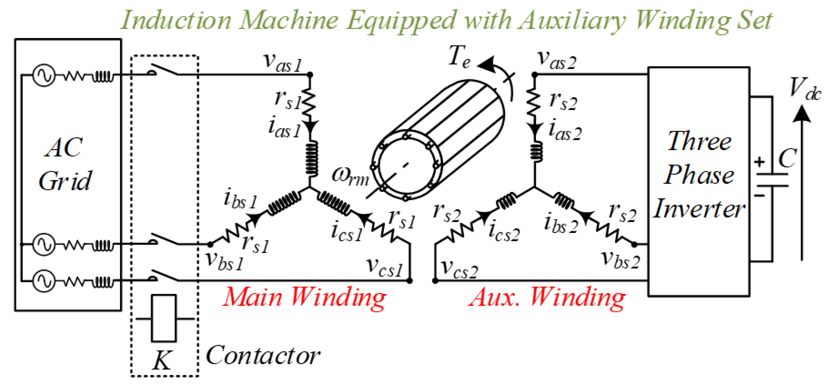
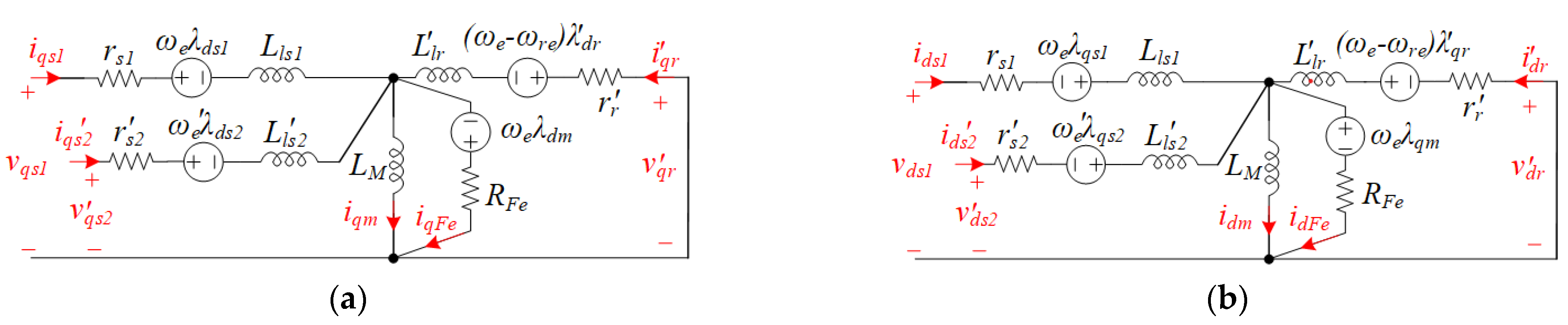
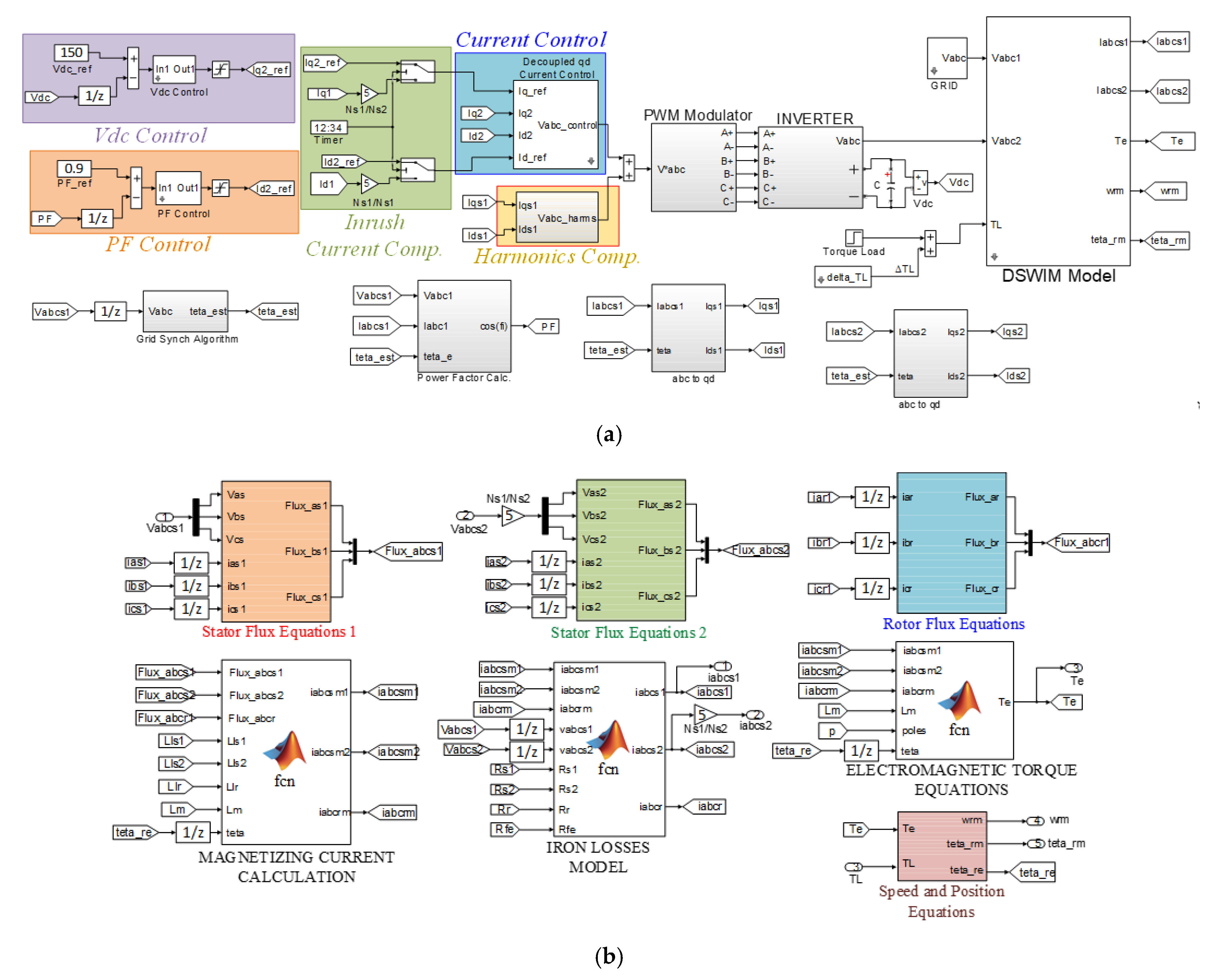
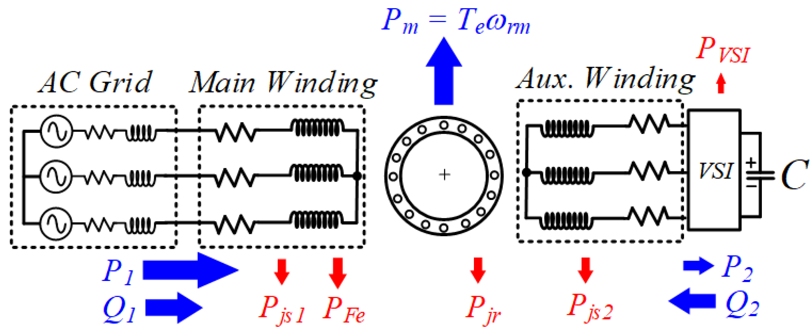
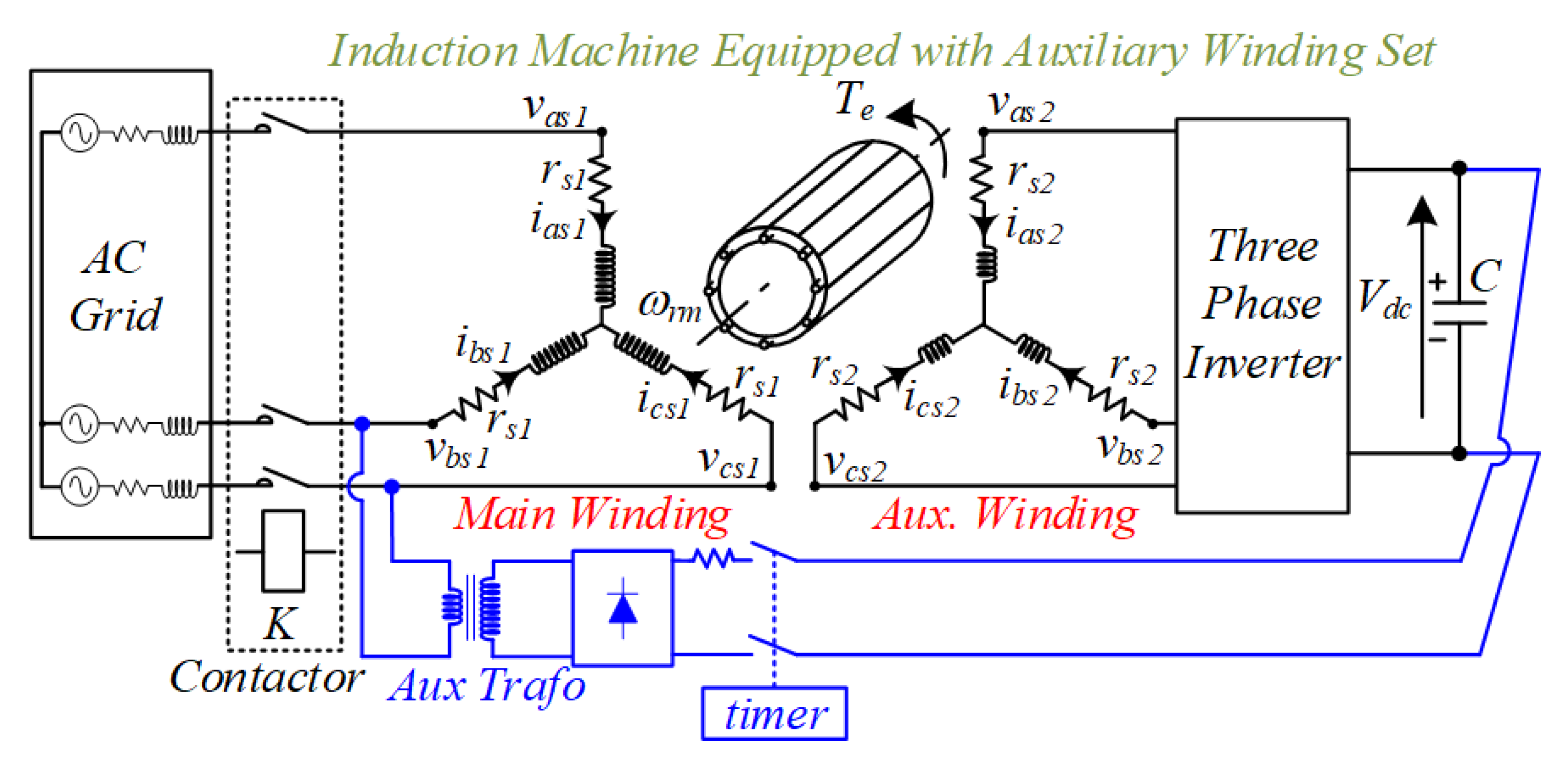
2. DWIM Model
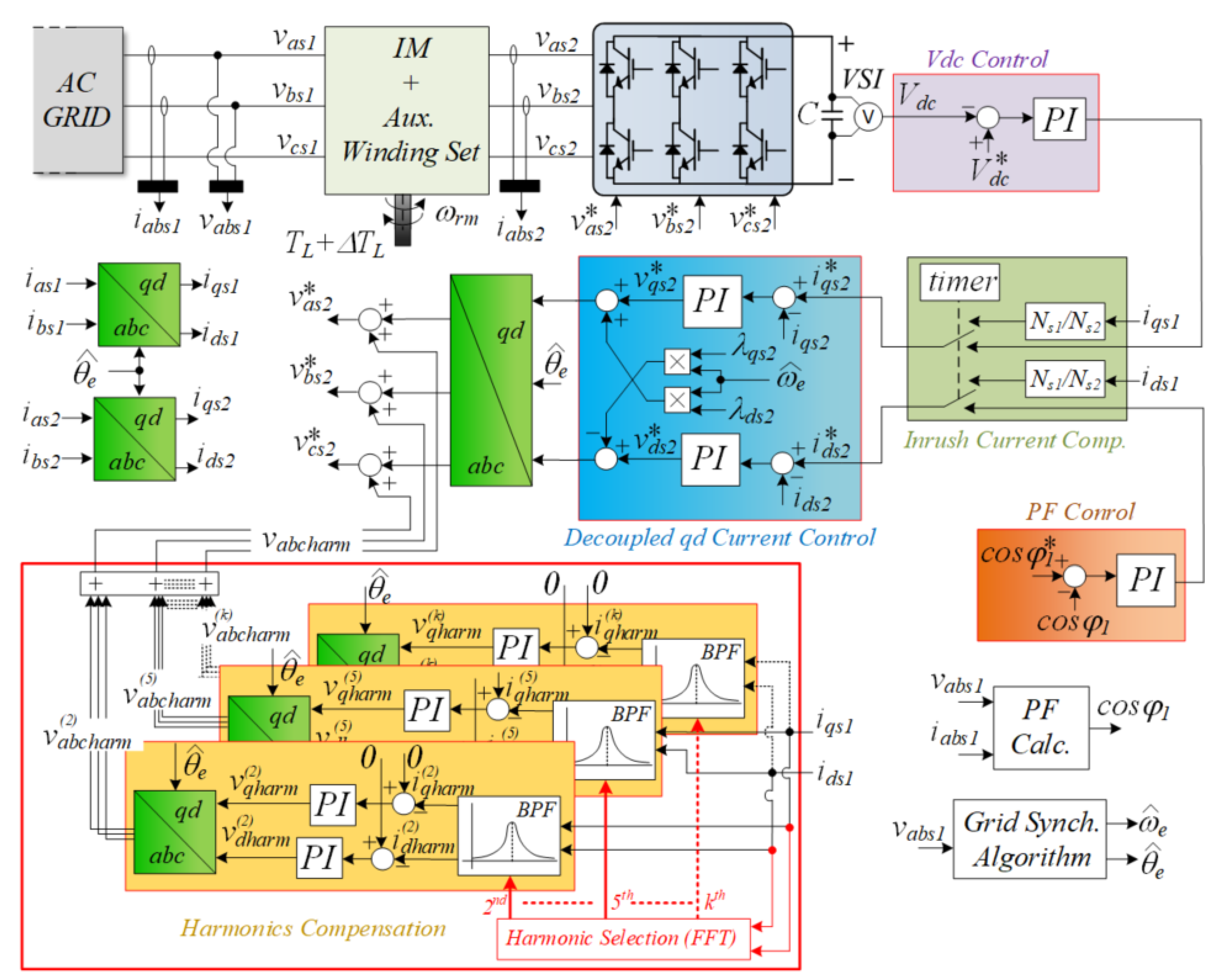
3. Control System
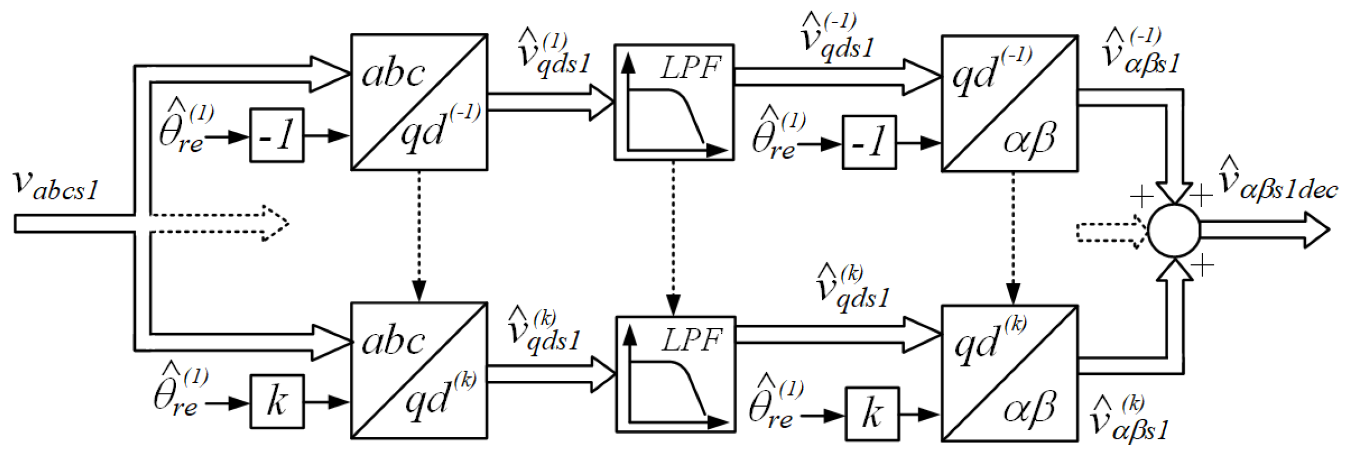
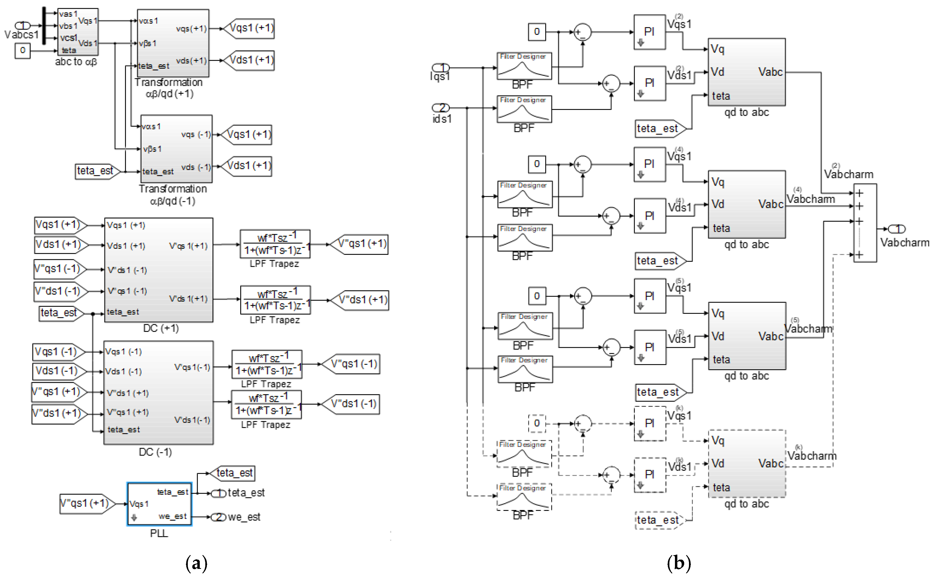
3.1. Grid Synchronization
3.2. Active and Reactive Power Control
3.3. Active Mitigation of Mechanical Vibrations
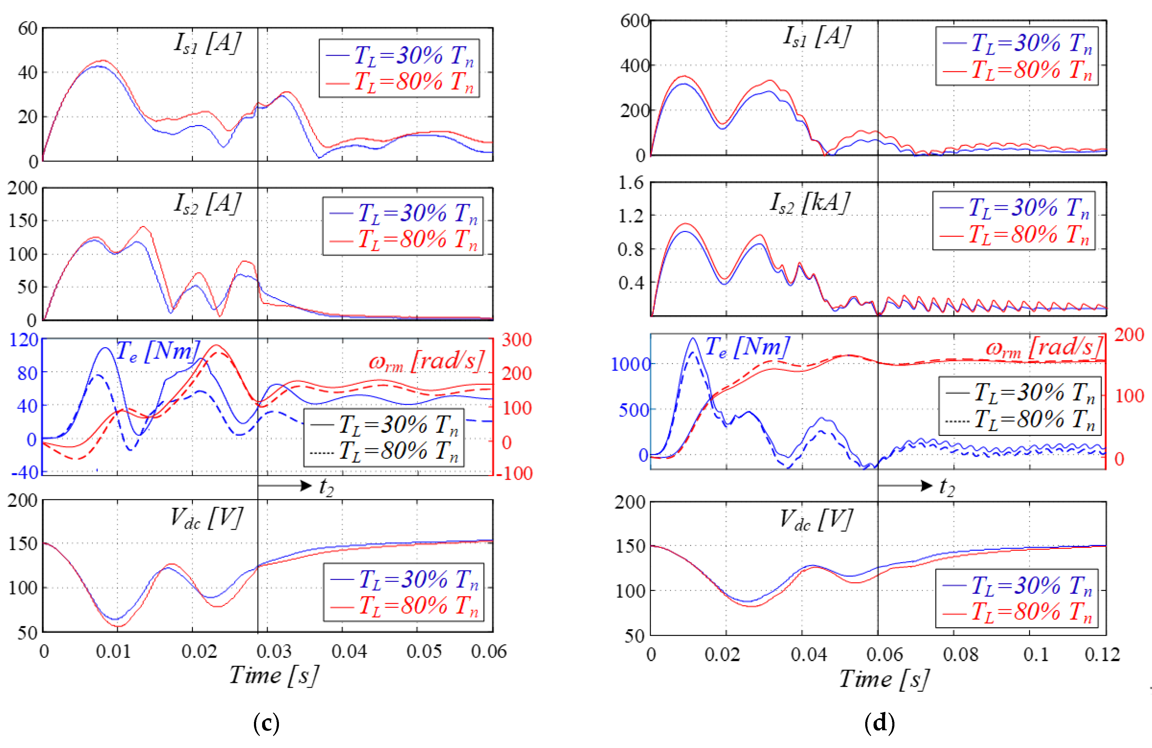
3.4. Inrush Current Mitigation during Startup
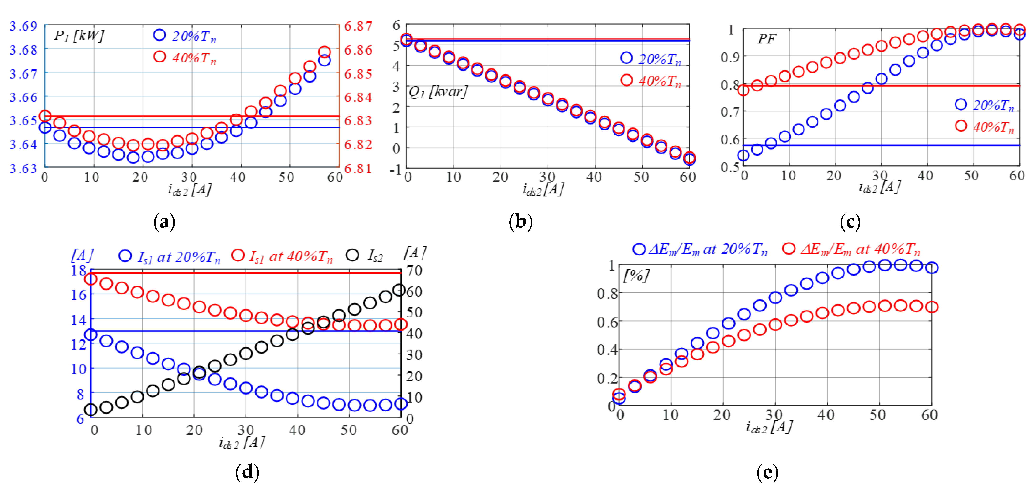
4. Performance Assessment of the Grid-Connected DWIM
5. Conclusions
Author Contributions
Funding
Institutional Review Board Statement
Informed Consent Statement
Data Availability Statement
Conflicts of Interest
References
- G1 IEC 60034-30-1:2014. Rotating Electrical Machines—Part 30-1: Efficiency Classes of Line Operated AC Motors; IEC: Geneva, Switzerland, 2014. [Google Scholar]
- Morimoto, S.; Tong, Y.; Takeda, Y.; Hirasa, T. Loss minimization control of permanent magnet synchronous motor drives. IEEE Trans. Ind. Electron. 1994, 41, 511–517. [Google Scholar] [CrossRef]
- Kim, S.; Yoon, Y.; Sul, S.; Ide, K. Maximum Torque per Ampere (MTPA) Control of an IPM Machine Based on Signal Injection Considering Inductance Saturation. IEEE Trans. Power Electron. 2013, 28, 488–497. [Google Scholar] [CrossRef]
- Uddin, M.N.; Nam, S.W. New Online Loss-Minimization-Based Control of an Induction Motor Drive. IEEE Trans. Power Electron. 2008, 23, 926–933. [Google Scholar] [CrossRef]
- Cacciato, M.; Consoli, A.; Scarcella, G.; Scelba, G. Indirect maximum torque per ampere control of induction motor drives. In Proceedings of the EPE, Aalb, Den, 2–5 September 2007; pp. 1–10. [Google Scholar]
- Attaianese, C.; Perfetto, A.; Tomasso, G. A space vector modulation algorithm for torque control of inverter fed induction motor drive. IEEE Trans. Energy Convers. 2002, 17, 222–228. [Google Scholar] [CrossRef]
- Kim, H.-J.; Lee, H.-D.; Sul, S.-K. A new PWM strategy for common-mode voltage reduction in neutral-point-clamped inverter-fed AC motor drives. IEEE Trans. Ind. Appl. 2001, 37, 1840–1845. [Google Scholar]
- Hava, A.M.; Kerkman, R.J.; Lipo, T.A. Carrier-based PWM-VSI overmodulation strategies: Analysis, comparison, and design. IEEE Trans. Power Electron. 1998, 13, 674–689. [Google Scholar] [CrossRef]
- Zhong, E.; Lipo, T.A. Improvements in EMC performance of inverter-fed motor drives. IEEE Trans. Ind. Appl. 1995, 31, 1247–1256. [Google Scholar] [CrossRef]
- Cacciato, M.; Caro, S.D.; Scarcella, G.; Scelba, G.; Testa, A. Improved space-vector modulation technique for common mode currents reduction. IET Power Electron. 2013, 6, 1248–1256. [Google Scholar] [CrossRef]
- Cacciato, M.; Consoli, A.; Scarcella, G.; Scelba, G.; Testa, A. A novel space-vector modulation technique for common mode emissions reduction. In Proceedings of the International Aegean Conference on Electrical Machines and Power Electronics, Bodrum, Turkey, 2–4 September 2007; pp. 199–204. [Google Scholar]
- Muljadi, E.; Lipo, T.A.; Novotny, D.W. Power Factor Enhancement of Induction Machines by Means of Solid-State Excitation. IEEE Trans. Power Electron. 1989, 4, 409–418. [Google Scholar] [CrossRef]
- Spée, R.; Wallace, A.K. Comparative Evaluation of Power Factor Improvement Techniques for Squirrel Cage Induction Motors. IEEE Trans. Ind. Appl. 1992, 28, 381–386. [Google Scholar] [CrossRef]
- Basak, S.; Chakraborty, C. Dual Stator Winding Induction Machine: Problems, Progress, and Future Scope. IEEE Trans. Ind. Electron. 2015, 62, 4641–4652. [Google Scholar] [CrossRef]
- Muteba, M.C.; Jimoh, A.A.; Nicolae, D.V. Improving three-phase induction machines power factor using single phase auxiliary winding fed by an active power filter. In Proceedings of the IEEE Conference AFRICON, Windhoek, South Africa, 13–15 September 2007; pp. 1–7. [Google Scholar]
- Malik, N.; Sadarangani, C.; Cosic, A.; Lindmark, M. Induction Machine at Uniy Power Factor with Rotating Power Electronic Converter. In Proceedings of the IEEE International Symposium SPEEDAM, Sorrento, Italy, 24–26 June 2012; pp. 401–408. [Google Scholar]
- Knight, A.M.; Salomon, J.C.; Haque, R.; Perera, N.; Toulabi, M.S. A grid-connected induction machine capable of operation at unity and leading power factor. In Proceedings of the IEEE Energy Conversion Congress and Exposition, Denver, CO, USA, 10–14 October 2013; pp. 238–245. [Google Scholar]
- Riley, C.M.; Lin, B.K.; Habetler, T.G.; Kliman, G.B. Stator current harmonics and their causal vibrations: A preliminary investigation of sensorless vibration monitoring applications. IEEE Trans. Ind. Appl. 1999, 35, 94–99. [Google Scholar] [CrossRef]
- Foti, S.; De Caro, S.; Testa, A.; Tornello, L.D.; Scelba, G.; Scarcella, G. Grid-Connected Open-end Winding Induction Motor Drives. In Proceedings of the International Symposium SPEEDAM, Sorrento, Italy, 24–26 June 2020; pp. 30–35. [Google Scholar]
- Basak, S.; Chakraborty, C.; Sinha, A.K. Dual Stator Induction Generator with Controllable Reactive Power Capability. In Proceedings of the IEEE Symposium ISIE, Instabul, Turkey, 1–4 June 2014; pp. 2584–2589. [Google Scholar]
- Marouani, K.; Nounou, K.; Benbouzid, M.; Tabbache, B. Power factor correction of an electrical drive system based on multiphase machines. In Proceedings of the IEEE First International Conference on Green Energy ICGE, Sfax, Tunisia, 25–27 March 2014; pp. 152–157. [Google Scholar]
- Ojo, O.; Davidson, I.E. PWM-VSI inverter-assisted stand-alone dual stator winding induction generator. IEEE Trans. Ind. Appl. 2000, 36, 1604–1611. [Google Scholar]
- Li, Y.; Hu, Y.; Huang, W.; Liu, L.; Zhang, Y. The Capacity Optimization for the Static Excitation Controller of the Dual-Stator-Winding Induction Generator Operating in a Wide Speed Range. IEEE Trans. Ind. Electron. 2009, 56, 530–541. [Google Scholar]
- Levi, E.; Sokola, M.; Boglietti, A.; Pastorelli, M. Iron loss in rotor-flux-oriented induction machines: Identification, assessment of detuning, and compensation. IEEE Trans. Power Electron. 1996, 11, 698–709. [Google Scholar] [CrossRef]
- Scarcella, G.; Scelba, G.; Cacciato, M.; Spampinato, A.; Harbaugh, M.M. Vector Control Strategy for Multidirectional Power Flow in Integrated Multidrives Starter-Alternator Applications. IEEE Trans. Ind. Appl. 2016, 52, 4816–4826. [Google Scholar] [CrossRef]
- Wee, S.-D.; Shin, M.-H.; Hyun, D.-S. Stator-flux-oriented control of induction motor considering iron loss. IEEE Trans. Ind. Electron. 2001, 48, 602–608. [Google Scholar]
- Golestan, S.; Guerrero, J.M.; Vasquez, J.C. Single-Phase PLLs: A Review of Recent Advances. IEEE Trans. Power Electron. 2017, 32, 9013–9030. [Google Scholar] [CrossRef]
- Zou, Z.; Liserre, M. Modeling Phase-Locked Loop-Based Synchronization in Grid-Interfaced Converters. IEEE Trans. Energy Convers. 2020, 35, 394–404. [Google Scholar] [CrossRef]
- De Donato, G.; De Scelba, G.; Borocci, G.; Capponi, F.G.; Scarcella, G. Fault-Decoupled Instantaneous Frequency and Phase Angle Estimation for Three-Phase Grid-Connected Inverters. IEEE Trans. Power Electron. 2016, 31, 2880–2889. [Google Scholar] [CrossRef]
- Nobile, G.; Scelba, G.; Cacciato, M.; Scarcella, G. Losses Minimization Control for an Integrated Multidrive Topology Devoted to Hybrid Electric Vehicles. IEEE Trans. Ind. Electron. 2019, 66, 8345–8360. [Google Scholar] [CrossRef]


| Winding 1 | Winding 2 | |
|---|---|---|
| Stator Voltage Vs | 400 Vrms | 60 Vrms |
| Stator Current Is | 25 Arms | 60 Arms |
| Stator Resistance Rs | 0.2147 Ω | 0.01 Ω |
| Leakage Inductance Lls | 0.991 mH | 40 μH |
| Rotor Resistance r’r | 0.2205 Ω | |
| Magnetizing Inductance LM | 64.2 mH | |
| Iron Losses Resistance RFe | 700 Ω | |
| Nominal Rotor Speed ωrm | 1460 rpm | |
| Mechanical Inertia J | 0.102 kgm2 | |
Publisher’s Note: MDPI stays neutral with regard to jurisdictional claims in published maps and institutional affiliations. |
© 2021 by the authors. Licensee MDPI, Basel, Switzerland. This article is an open access article distributed under the terms and conditions of the Creative Commons Attribution (CC BY) license (https://creativecommons.org/licenses/by/4.0/).
Share and Cite
Tornello, L.D.; Foti, S.; Cacciato, M.; Testa, A.; Scelba, G.; De Caro, S.; Scarcella, G.; Rizzo, S.A. Performance Improvement of Grid-Connected Induction Motors through an Auxiliary Winding Set. Energies 2021, 14, 2178. https://doi.org/10.3390/en14082178
Tornello LD, Foti S, Cacciato M, Testa A, Scelba G, De Caro S, Scarcella G, Rizzo SA. Performance Improvement of Grid-Connected Induction Motors through an Auxiliary Winding Set. Energies. 2021; 14(8):2178. https://doi.org/10.3390/en14082178
Chicago/Turabian StyleTornello, Luigi Danilo, Salvatore Foti, Mario Cacciato, Antonio Testa, Giacomo Scelba, Salvatore De Caro, Giuseppe Scarcella, and Santi Agatino Rizzo. 2021. "Performance Improvement of Grid-Connected Induction Motors through an Auxiliary Winding Set" Energies 14, no. 8: 2178. https://doi.org/10.3390/en14082178
APA StyleTornello, L. D., Foti, S., Cacciato, M., Testa, A., Scelba, G., De Caro, S., Scarcella, G., & Rizzo, S. A. (2021). Performance Improvement of Grid-Connected Induction Motors through an Auxiliary Winding Set. Energies, 14(8), 2178. https://doi.org/10.3390/en14082178