1. Introduction
Despite steady positions of silicon solar elements (currently, 94% of the global market is ruled by Si-based solar cells) the relevance of the development of thin-film photovoltaic energy converters (PECs) is not questioned or in doubt. Over the last 20 years, the study of exciting and versatile thin-film technology has grown fast, and current results are comparable to results with silicon [
1].
Thin-film technology has several advantages over silicon analogs; first of all, it is a low-consumption material that utilizes simple, cost-effective production methods. Second, it has the ability to efficiently convert scattered sunlight into electricity, at a fairly high efficiency (up to 20%). Deposition of thin-film elements is possible on a surface of nearly any configuration (e.g., automobile surfaces, glass facades of buildings), which significantly increases the specific area of the functional surface of PECs [
2].
The semiconducting compound (CZTS) is made up of earth-abundant, low-cost and non-toxic elements, which make it an ideal candidate to replace Cu(In, Ga)Se2 (CIGS) and CdTe solar cells (which face material scarcity and toxicity issues). The device performance of CZTS-based thin-film solar cells has been steadily improving over the past 20 years, and they have now reached near-commercial efficiency levels (10%).
Chemical compounds like kesterite—Cu
2ZnSn(S, Se)
4 or CZTS(Se)—adopt the crystalline kesterite form. They have direct bandgaps around 1.5 and 1.1 eV and high absorption coefficients (>104 cm
−1), both of which are essential properties for photovoltaic applications [
3].
These properties allow kesterite PECs to convert the radiation of an optical spectral band into electric current (with minimal losses) at a thickness of only 2–3 microns. As of 2018, the efficiency of CZTS-PEC has reached 12.7% [
4].
These achievements prove that CZTS-based solar cells have the potential to be used for large-scale deployment in photovoltaics.
To facilitate further development of CZTS-solar technology, it is necessary to solve some technological issues. One issue is the need to obtain a dielectric layer for kesterite PECs on a metal plate that can be used for roofing.
A major problem in insulating the solar cell from the metal plate is the lack of varnishable dielectric polymer materials that are resistant to the temperature conditions of the kesterite solar cell manufacturing process. The main requirements for varnishing are: resistance to short-term (5–30 min) temperatures of about 600 °C, optical transparency, dielectric properties, and good adhesion to steel and molybdenum.
The most high-temperature-resistant polymer is siloxane. Siloxane is chemically stable up to temperatures of about 300 °C [
5]. However, the minimum temperature resistance to withstand the kesterite synthesis process requires tolerances within limits of 500–600 °C, depending on the chosen method. Varnishes and enamels based on siloxane are capable of maintaining resistance at temperatures over 300 °C by transferring heat to a substrate through a heat-conducting disperse phase—the filler.
According to classical concepts of solid-state physics [
6,
7], electron transfer of heat and charge is the most efficient. Thus, generally-used used industrial fillers have excellent metallic-type electrical conductivity. Fine powders of aluminum or graphite are frequently selected for this purpose. Their thermal conductivity is within 237 W⋅m
−1⋅K
−1 (for aluminum) and 25–470 W⋅m
−1⋅K
−1 (for various forms of carbon), with an electrical resistance on the order of 5⋅10
−6–30⋅10
−6 Ω⋅m (
Table 1). Other metal oxides are used as dyes. They do not transfer heat to the substrate, but they have excellent dielectric characteristics (
Table 1).
However, none of these fillers can be used to obtain high thermal conductivity with extremely low electrical conductivity. That could be achieved using materials in which the phonon mechanisms of heat transfer were efficient but the electron mechanisms were limited. Materials with suitable characteristics include beryllium oxide (thermal conductivity 272 W⋅m
−1⋅K
−1, electrical conductivity 8⋅10
−13–4⋅10
−1 Ω
−1cm
−1 [
22]) and undoped ZnO (thermal conductivity 50 W⋅m
−1⋅K
−1, electrical conductivity 10
−7–10
−10 Ω
−1cm
−1) [
23].
The working concept behind the research presented here was the replacement of metal and carbon fillers in industrial varnishes with a nonconducting filler with good heat conductivity.
2. Materials and Methods
The research objectives included: obtaining polymer coating components from well-known industrial products (e.g., high-temperature enamel and heat-conducting paste KPT-8); obtaining a highly dispersed emulsion of polymer coating components with a given viscosity; developing technology for applying the composition to the surface; studying the thermal resistance and electrical strength of the coatings.
As a substrate, we used polished scraps of low-grade sheet roofing steel (GOST 8075—56) with a size of 30x15mm. As a polymer base, a siloxane varnish was used in the composition of a heat-resistant silicone enamel DALI, (GOST TU 2312-114-13238275-2013).
The filler used was a ZnO powder, according to GOST 202-84 grades BTs0 and BTs1, in the composition of a heat-conducting paste KPT-8 (GOST 19783-74). Powder was not separately emitted from the paste because it was made on an organic silicon polymeric basis, which was compatible with the used varnish.
Films were obtained by using spin-coating at a shaft rotational speed of 1200 rpm for 1 s.
The surface of the obtained films was investigated using profilometry on a MicroSpy® FT device. Optical microscopy was performed using a Digital Microscope Electronic Magnifier digital microscope. Differential scanning calorimetry (DSC) was performed on a DSC 204 F1 Phoenix instrument (Netzsch).
The sample (~20 mg) was placed in a corundum crucible and heated at a rate of 10 °C/min in a nitrogen atmosphere (flow 40 mL/min) up to 550 °C. Then, cooling was carried out at the same rate (to check the reversibility of the heating processes). An empty corundum crucible was used as a reference sample.
Electrical measurements were performed using a VC9808 precision multimeter.
The research of thermal properties was conducted via direct heating of a film surface on a metal plate by a dryer in temperature ranging from 50–600 °C. The substrate was in thermal contact with the heat-removing base, which made it possible to obtain a thermal conductivity gradient.
The heating duration at each point was 10 s, the temperature at each subsequent point increased by 50 °C. The temperature difference between films on the side of the open surface and those on the side of the substrate were defined using two thermocouple instruments for thermal measuring based on chromel–alumel alloys, along with two VC9808 devices.
3. Results
Below are the results of measurements of the obtained films (varnish with an oxide filler). The measurements were carried out under conditions close to the conditions for the synthesis of a thin film of kesterite over a varnish applied to a metal substrate. These conditions needed to be met, since a thin film must be synthesized on a layer of varnish applied to a metal plate under these conditions in order to create a CZTS solar energy converter.
The results proved the suitability of the coating for use as an insulating layer.
3.1. Microstructure and Electrical Properties
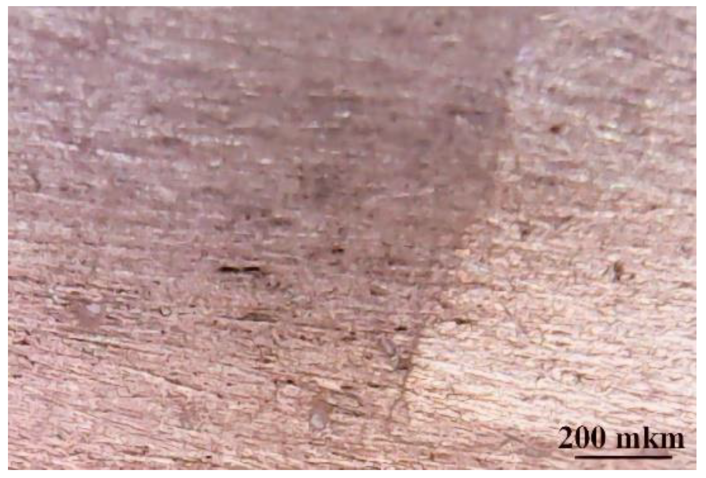
Optical microscopy data are presented in
Figure 1. The contrast in the right of the image shows the transition between the surface of the film and the ground surface of the metal. The film with filler has a light dairy shade. Metal inhomogeneities have been reduced by filling with varnish.
The electrical resistance of the film exceeded the limit of the range of used measuring devices (and was thus more than 2000 MΩ). Therefore, the leakage current of the synthesized heat-conducting films did not exceed 10−9A. At operating currents of an element about 100 mA, this denoted a value of no more than 10−3%. Thus, the received films were dielectric.
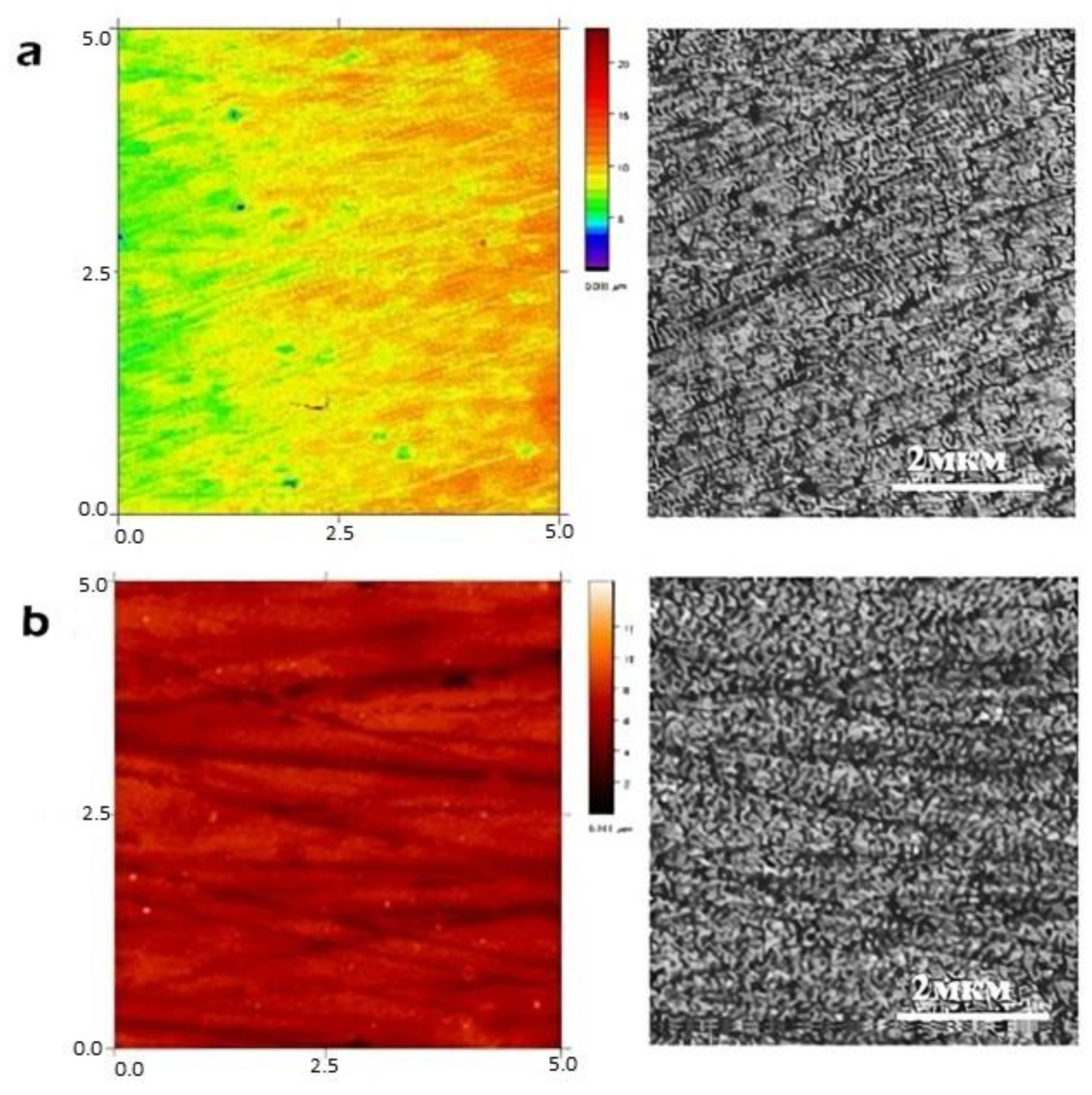
The topology of the film surface at the microscopic level is presented in
Figure 2. The profilometry data demonstrated a good distribution of the covering on the substrate; the film was homogeneous and smooth. The difference in heights in the explored area were on the order of 16–18 μm. This was probably determined by the method of sedimentation of the suspension and its rheological characteristics.
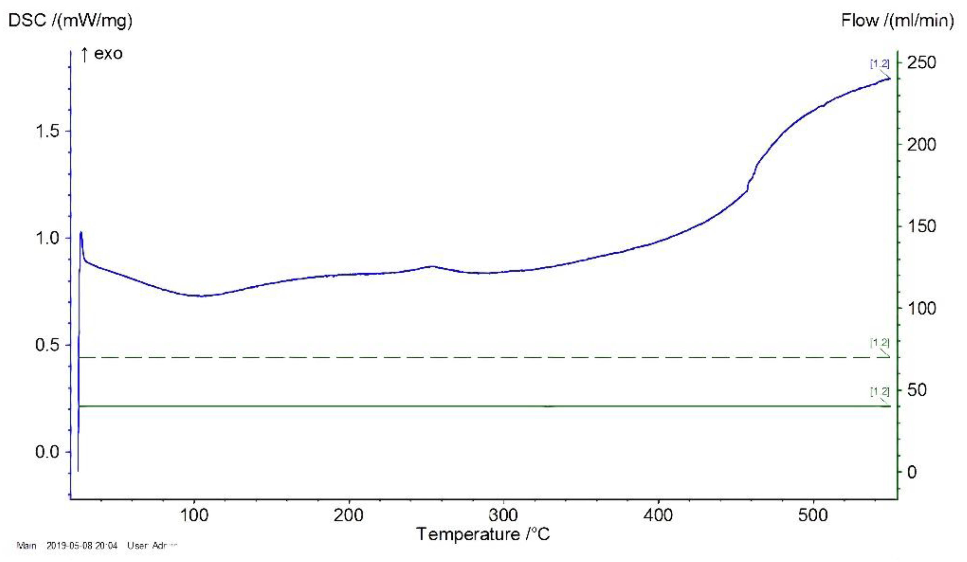
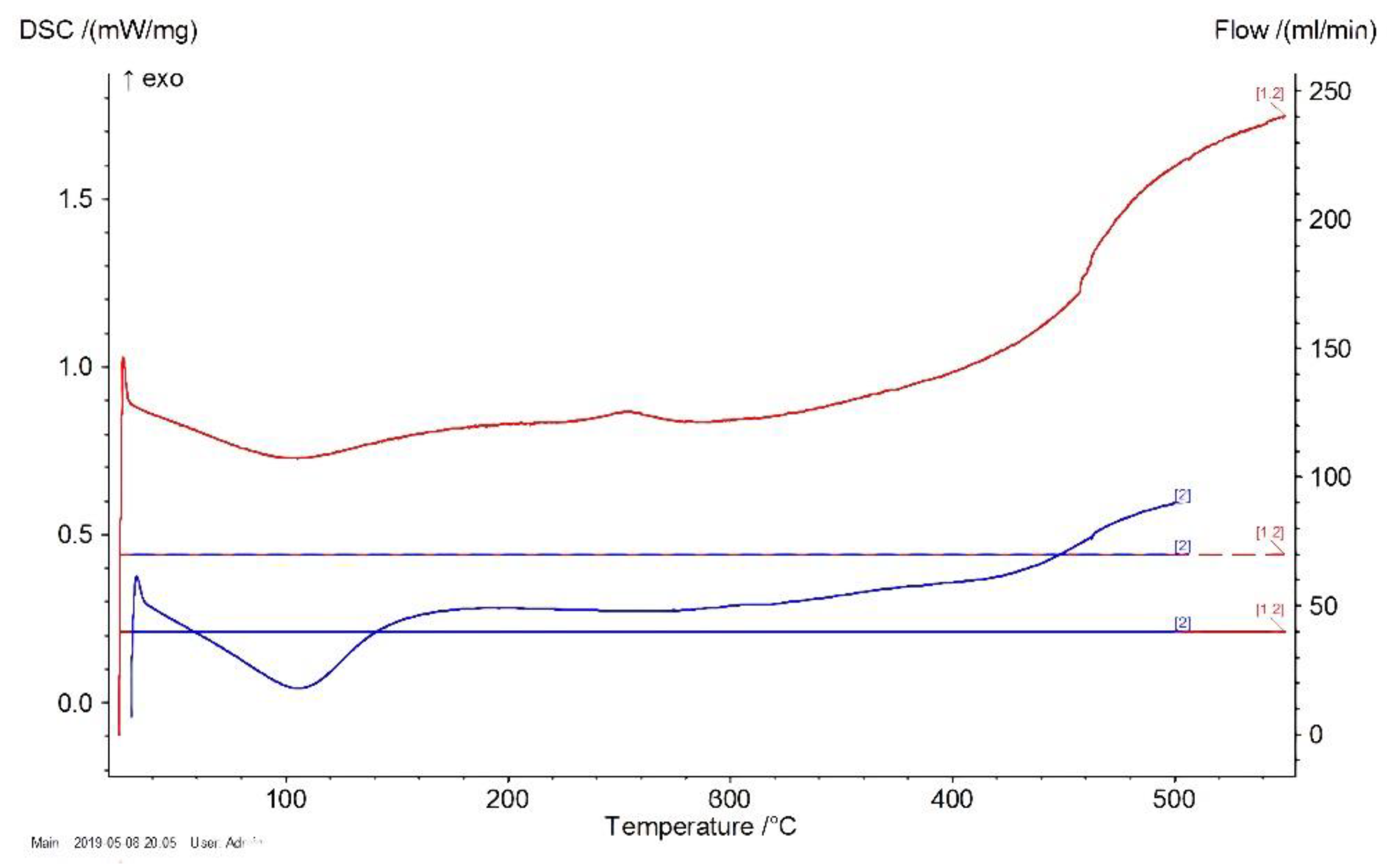
DSC results are presented in
Figure 3 and
Figure 4. The temperature (°C) is shown on the Abscissa axis and the specific heat absorption power (mW/mg) is shown on the Ordinate axis.
As shown in
Figure 3, the processing of a glass transition of polysiloxane without excipient occurred in a temperature range of 402–422 °C. A similar result was obtained in the case of a varnish filled with ZnO, as shown in
Figure 4.
Consequently, during the use of quasistatic heating at a speed of 20 °/min, the filler did not lead to a significant change in the temperature stability of the siloxane coatings.
The measurement of the temperature gradient upon heating was the most suitable experiment to test whether the ZnO filler as effective in increasing the thermal stability of the film. It was assumed that the filler would reduce the degree of overheating of the film by increasing the efficiency of heat transfer to the substrate.
3.2. The Study of Thermophysical Characteristics: Mathematical Description of Thermophysical Processes in the Studied System
A boundary value problem—concerning the heat conductivity of a flat wall at boundary conditions of the first kind—was used for mathematical descriptions of the processes of heat conductivity in the studied films upon heating. Heat conduction processes can be described by the below equation—which in this case takes the appearance of a differential Equation (1). In case of quasistationary conditions (heating occurred periodically, typically within 10 s (most of the time, t) in the absence of internal sources of warmth), the differential equation of heat conductivity of this system takes this form:
If we assume that the temperature changes only perpendicularly to the plane of the substrate, then
and the differential equation can be as follows:
The heat transfer equation for the system under study was received by double integration of Equation (2) and has the form:
where
C1 and
C2 represent constants characterizing the process of heat exchange between a film and a substrate.
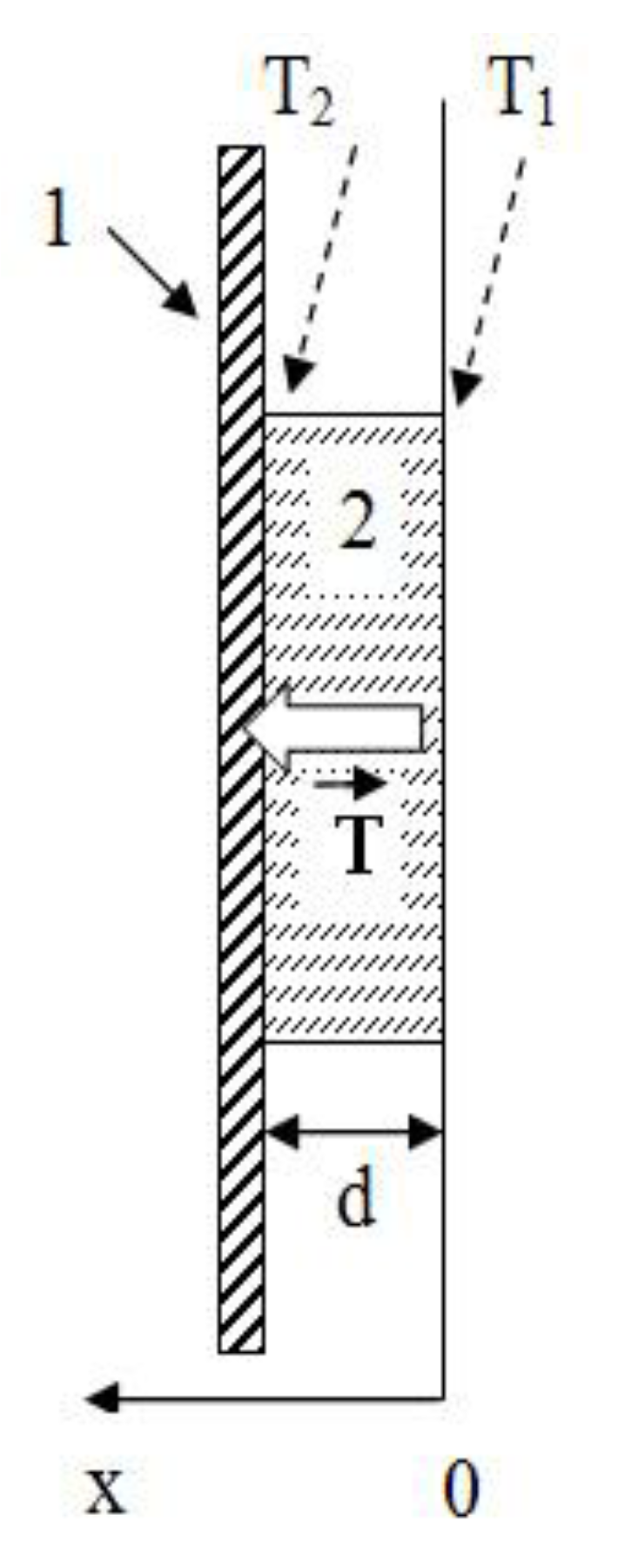
Next, there are initial boundary conditions: d = 10–50 μm (layer thickness), T = T1 at x = 0, T = T2 at x = d find C1 and C2:
at x = 0: T = T1 = C2;
at x = d: T = T2 = C1d + C2.
An equation of motion of the temperature front was received by substituting Equation (4) into Equation (3):
The following
Figure 5 shows a graphical representation of the conditions of the boundary problem being solved:
4. Discussion
Determination of the Quantitative Parameters of the Effectiveness of the Filler
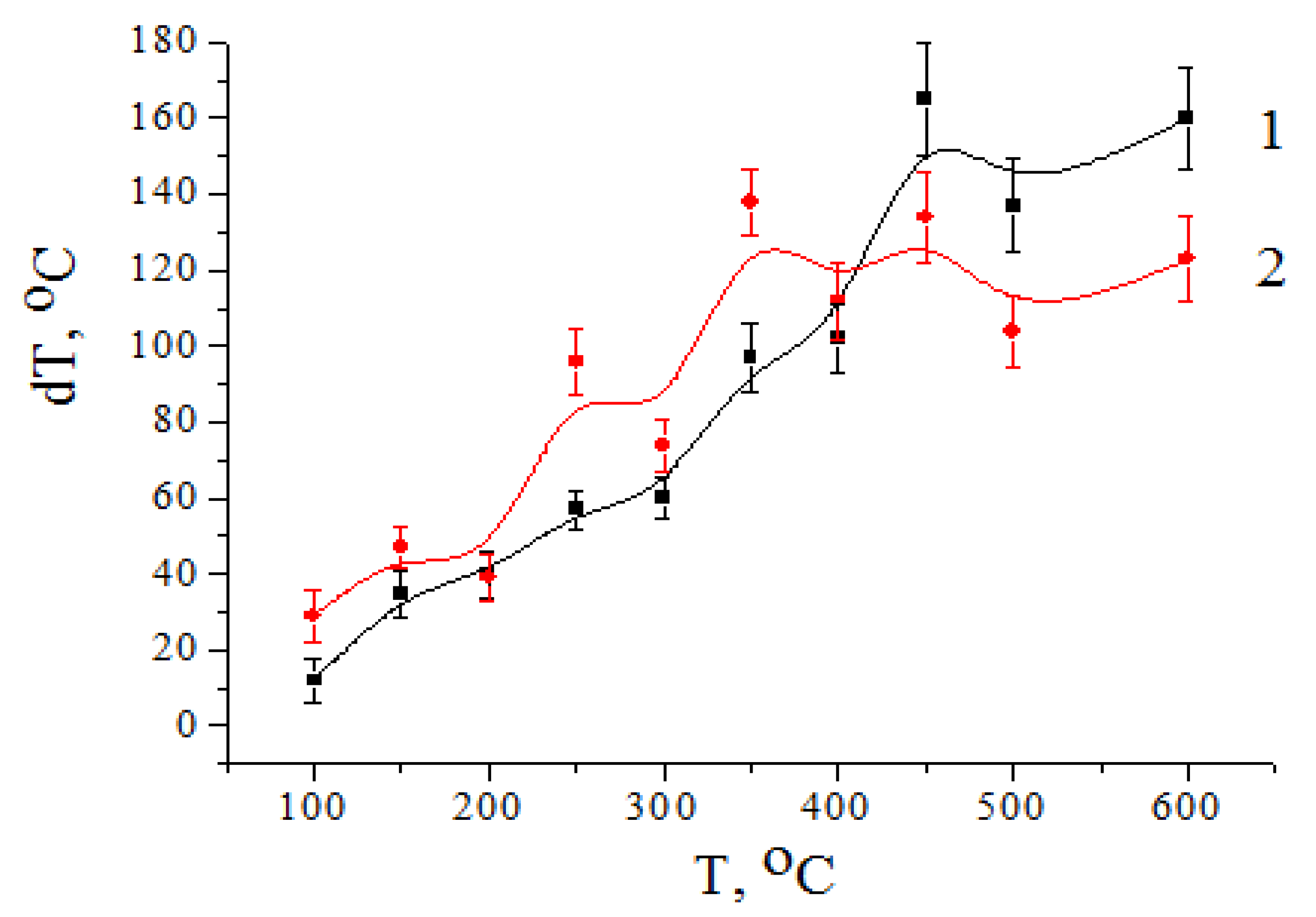
In
Figure 6, the temperature dependences of the temperature gradients in the films obtained (both without using ZnO filler (curve 1) and using ZnO filler (curve 2)) are presented. It can be seen that the value of the temperature gradient Δ
T in the sample volume increased with increasing temperature
T, which indicated an increase in heat flux
q through the sample with a thickness
d:
The Fourier’s law of heat conduction to determinate heat flux density
q is [
24]:
After substituting
C1 for
and replacing
T1 −
T2 on Δ
T in Equation (7):
The ratio of thermal conductivity coefficients of substrates with and without filler in the case of equivalence of external heat fluxes can be estimated by the ratio of the corresponding values of temperature gradients:
Proceeding from the nature of the change of a temperature gradient in the volume of control (a curve 1) and ZnO-filled (a curve 2) samples, it was possible to conclude that the heat conductivity of both films did not differ significantly up to temperatures of about 450 °C.
It can be seen that the growth rate of the temperature gradient for films with a filler was somewhat higher than the growth rate of the temperature gradient in the control sample. Over 450 °C, this tendency did not remain.
Temperature gradient dynamics of growth in films with filler were reduced in comparison with the control sample. The ZnO filler began to limit the growth of heat flux through the sample, stabilizing the temperature gradient at 120–140 °C. The dispersion of values was about 20 °C.
The ratios of thermal coefficients
—which characterize the heat conductivity efficiency of ZnO fillers—are presented in
Table 2 for temperatures above 450 °C.
This ratio averaged about 0.94. Thus, additive significantly changed the constant of heat conductivity of the material of the film in the specified temperature range.
As shown in
Table 2, the thermal conductivity coefficient ratio averaged around 0.93. Thus, the addition of ZnO as a filler increased the thermal conductivity of the film material in the specified temperature range. At the same time, the film did not undergo destruction.
5. Conclusions
1. Polyorganosiloxane coverings filled with heat-conducting oxide powder were obtained. Their main functional properties were investigated.
2. The use of industrial heat-resistant enamel and powders of unalloyed ZnO in the composition of heat-conducting KPT-8 paste allowed us to obtain heat-conducting electrical insulating coverings capable of working in the temperature range required for the synthesis of kesterite (500–600 °C).
3. The mathematical model of thermal processes in film was carried out. The equation of the process of heat transfer was received and numerical solutions were found (in the form of the ratios of thermal conductivity coefficients for temperatures above 450 °C).
4. The data of the thermal experiments confirmed the possibility of using a dielectric to increase the heat resistance of the coating. At temperatures that exceeded the limits of thermal stability of the natural spectrum of coatings, thermal activation of diffusion processes of cationic or ionic sublattices occurred in the dielectric.
Author Contributions
Conceptualization, A.A.T., A.S.D. and P.P.G.; methodology, A.S.D.; software, O.Y.I., O.S.P.; validation, A.S.D., P.P.G. and A.A.T.; formal analysis, A.A.T.; investigation, A.A.T.; resources, M.B.; data curation, A.S.D.; writing—original draft preparation, A.A.T.; supervision, M.B.; project administration, A.S.D. All authors have read and agreed to the published version of the manuscript.
Funding
This research received no external funding.
Institutional Review Board Statement
Not applicable.
Informed Consent Statement
Not applicable.
Data Availability Statement
Not applicable.
Acknowledgments
The study was performed in the scope of the: Project H2020/MSCA/RISE/SSHARE number 871284 project and INR—Romania Cooperation Program Projects: Nos. 268/20.05.2020 item 59, 267/20.05.2020 item 25; Theme 04-4-1121-2015/2020 Projects 268/20.05.2020, items 47 and 269/20.05.2020, item 50; Theme 04-4-1141-2020/2022 Projects 268/20.05.2020, item 73 and 269/20.05.2020, item 76.
Conflicts of Interest
The authors declare no conflict of interest.
References
- Jackson, P.; Wuerz, R.; Hariskos, D.; Lotter, E.; Witte, W.; Powalla, M. Effects of heavy alkali elements in Cu(In, Ga)Se2 solar cells with efficiencies up to 22.6%. RRL 2016, 10, 583–586. [Google Scholar]
- Barnett, A.; Kirkpatrick, D.; Honsberg, C.; Moore, D.; Wanlass, M.; Emery, K. Very high efficiency solar cell modules. Prog. Photovolt Res. Appl. 2009, 17, 75–83. [Google Scholar] [CrossRef]
- Ito, K. Copper Zinc Tin Sulfide-Based Thin Film Solar Cells; Wiley Books: Hoboken, NJ, USA, 2015. [Google Scholar]
- Bernardini, G.P.; Borrini, D.; Caneschi, A. EPR and SQUID magnetometry study of Cu2FeSnS4 (stannite) and Cu2ZnSnS4 (kesterite). Phys. Chem. Minerals. 2000, 27, 453–461. [Google Scholar] [CrossRef]
- Bazhant, V.; Hvalovski, V.; Ratouski, I. Silicones—Silicon Organic Compounds, Their Production, Properties and Applications; GNTI Chem lit.: Moscow, Russia, 1960; p. 710. [Google Scholar]
- Wert, C.A.; Thomson, R.M. Physics of Solids; McGraw-Hill: New York, NY, USA, 1964; 436p. [Google Scholar]
- Kittel, C. Introduction to Solid State Physics; John Wiley: New York, NY, USA, 1976. [Google Scholar]
- Moiseeva, N. Melting and Boiling Point of Various Substances. 2020. Available online: http://temperatures.ru/pages/temperatura_plavleniya_i_kipeniya (accessed on 9 April 2021).
- Moyes, N. List of Thermal Conductivities. 2021. Available online: https://en.wikipedia.org/wiki/List_of_thermal_conductivities (accessed on 9 April 2021).
- Honeywell. Dielectric Constant Table. 2011. Available online: https://www.honeywellprocess.com/library/marketing/tech-specs/Dielectric%20Constant%20Table.pdf (accessed on 9 April 2021).
- Giancoli, D.C. General Physics; Prentice-Hall: Hoboken, NJ, USA, 1984; Volume 2, 892p. [Google Scholar]
- AZoM. Graphite (C)—Classifications, Properties and Applications of Graphite. Available online: https://www.azom.com/article.aspx?ArticleID=1630 (accessed on 9 April 2021).
- Takeda, M.; Onishi, T.; Nakakubo, S.; Fujimoto, S. Physical properties of iron-oxide scales on Si-containing steels at high temperature. Mater. Trans. 2009, 50, 2242–2246. [Google Scholar] [CrossRef]
- Dababneh, M.S.; Ayoub, N.Y.; Odeh, I.; Laham, N.M. Viscosity, Resistivity and Surface Tension Measurements of Fe3O4 Ferrofluid. J. Magn. Magn. Mat. 1993, 125, 34–38. [Google Scholar] [CrossRef]
- AZoM. Titanium Dioxide—Titania TiO2. Available online: https://www.azom.com/article.aspx?ArticleID=1179 (accessed on 9 April 2021).
- AZoM. Aluminium Oxide—Al2O3. Available online: https://www.azom.com/properties.aspx?ArticleID=52 (accessed on 9 April 2021).
- Whitaker, J.C. The Electronics Handbook, 2nd ed.; CRC Press and IEEE Press: Boca Raton, FL, USA, 1996. [Google Scholar]
- AZoM. Silica-Silicon Dioxide (SiO2). Available online: https://www.azom.com/article.aspx?ArticleID=1114 (accessed on 9 April 2021).
- Subramanian, M.A.; Shannon, R.D.; Chai, B.H.T. Dielectric constants of BeO, MgO, and CaO using the two-terminal method. Phys. Chem. Miner. 1989, 16, 741–746. [Google Scholar] [CrossRef]
- Wu, X.; Lee, J.; Varshney, V. Thermal Conductivity of Wurtzite Zinc-Oxide from First-Principles Lattice Dynamics—A Comparative Study with Gallium Nitride. Sci. Rep. 2016, 6, 22504. [Google Scholar]
- Rodnyi, P.A.; Khodyuk, I.V. Optical and luminescence properties of ZnO (Review). Opt. Spectrosc. 2011, 111, 776–785. [Google Scholar] [CrossRef]
- Kiyko, V.S.; Akishin, G.P.; Makurin, Y.N.; Ivanovskiy, A.L. Method for Producing Beryllium Oxide-Based Electrically Conductive Ceramic. RU 2326091; filed 26 December 2005, and issued 10 June 2008,
- Bale, S.; Rahman, S. Role of ZnO in Dc Electrical Conductivity of Lithium Bismuthate Glasses, Int. Sch. Res. Not. 2013, 126805. [Google Scholar]
- Shubin, M.A. Lectures on Equations of Mathematical Physics; Moscow Center for Continuous Mathematical Education: Moscow, Russia, 2003; 303p. [Google Scholar]
| Publisher’s Note: MDPI stays neutral with regard to jurisdictional claims in published maps and institutional affiliations. |
© 2021 by the authors. Licensee MDPI, Basel, Switzerland. This article is an open access article distributed under the terms and conditions of the Creative Commons Attribution (CC BY) license (https://creativecommons.org/licenses/by/4.0/).


 ,
, 


