Article

Innovative Energy Management System for MVDC Networks with Black-Start Capabilities

1
Iberdrola Innovation Middle East, Doha 210177, Qatar
2
Department of Electronic and Electrical Engineering, University of Strathclyde, Glasgow G1 1XW, UK
*
Author to whom correspondence should be addressed.
Energies 2021, 14(8), 2100; https://doi.org/10.3390/en14082100
Submission received: 15 February 2021 / Revised: 4 April 2021 / Accepted: 7 April 2021 / Published: 9 April 2021
(This article belongs to the Special Issue Innovative HVDC and MVDC Connection Schemes for Offshore Wind Farms)

Abstract

:
Medium voltage DC (MVDC) networks are attracting more attention amid increased renewables penetration. The reliability of these DC systems is critical, especially following grid contingencies to maintain critical loads supply and provide ancillary services, such as black-start. This paper proposes an innovative energy management system (EMS) to maintain reliable MVDC network operation under prolonged AC grid contingencies. Similar EMS designs in literature tend to focus on limited operating modes and fall short of covering comprehensive elongated blackout considerations. The proposed EMS in this paper aims to preserve the distribution network functionality of the impacted MVDC system through maintaining a constant DC bus voltage, maximizing critical load supply duration, and maintaining the MVDC system black-start readiness. These objectives are achieved through controlling generation units between Maximum Power Point Tracking (MPPT) and Voltage Regulation (VR) modes, and implementing a smart load shedding and restoration algorithm based on network parameters feedback, such as storage State of Change (SoC) and available resources. Practical design considerations for MVDC network participation in AC network black start, and the following grid synchronization steps are presented and tested as part of the EMS. The proposed system is validated through simulations and scaled lab setup experimental scenarios.

1. Introduction

The share of electricity generation from renewable energy sources (RES) is soaring on a global scale due to their maturing technology and rapidly falling costs. Bloomberg predicts wind and solar energy to contribute to 50% of the world electricity generation by 2050. Batteries are also expected to have an increasingly important role to minimize the RES intermittency impact [1]. Medium and utility scale RES grid integration has traditionally been performed using high voltage AC (HVAC) or DC (HVDC) systems. Technology selection depends on several techno-economic factors, such as network stability and transmission distance [2].
An increasingly attractive trend is emerging to establish intermediate collecting medium voltage DC (MVDC) distribution networks that integrate the output from various renewables, such as PV and offshore wind farms [3,4,5]. Key industrial manufacturers are proposing the use of MVDC solutions in distribution networks, such as the MVDC Plus technology from Siemens [6]. A recent paper from ABB also highlights some implemented MVDC projects in various fields, such as marine applications, distribution networks, and RES collection grids [7]. A recent example of such implementation in 2018 is for MVDC converters connecting distributed generation and load centers in the UK [7]. Another example for MVDC applications is the Angle-DC project, which aims to convert distribution MVAC lines operation to MVDC to increase power transfer limit and improve controllability [8,9].
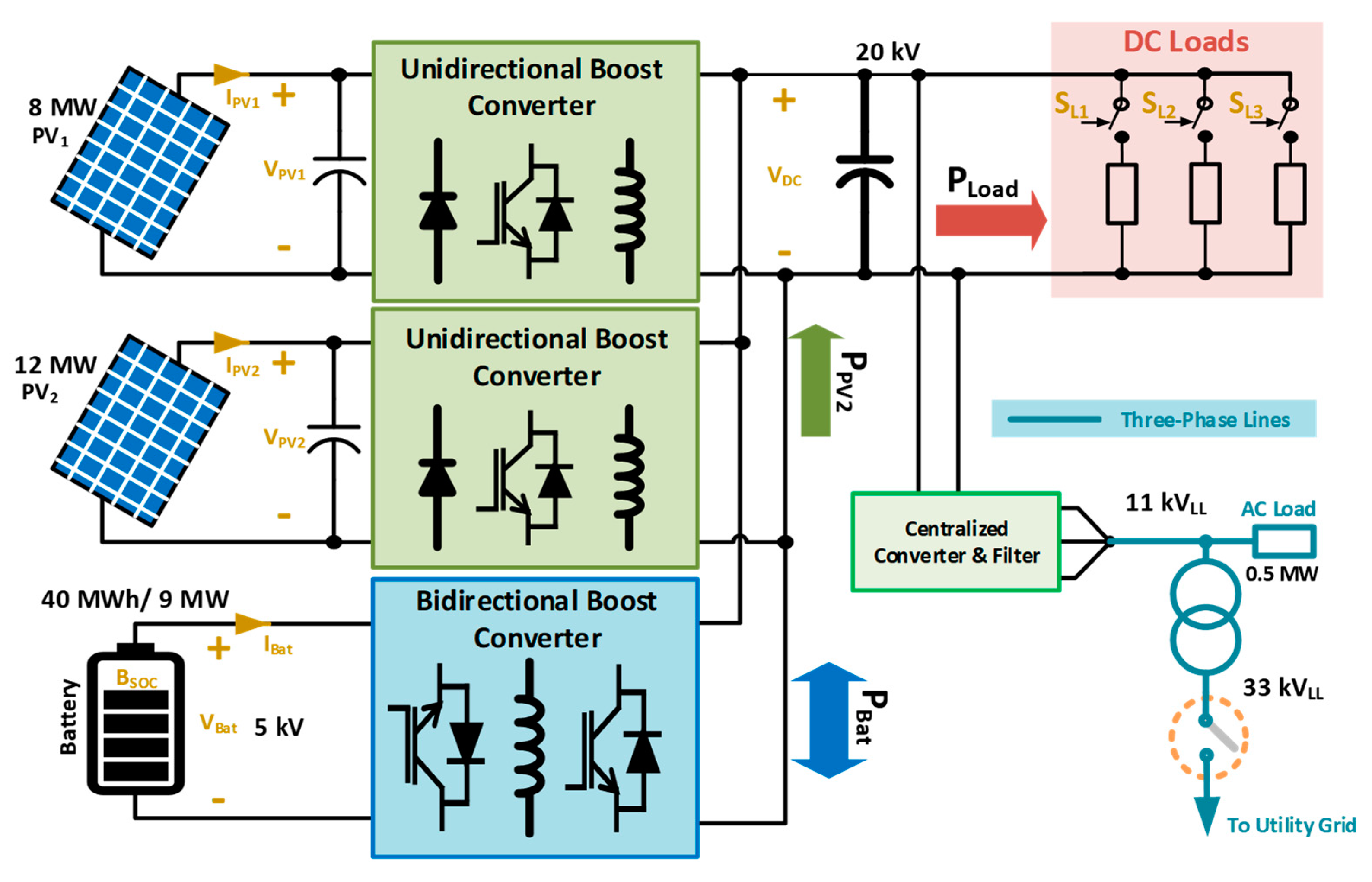
When isolated from the grid under network contingency, distribution systems with local generation can be considered as independent electrical entities that require their own energy management system (EMS) to maintain stable DC bus voltage for load supply reliability and ancillary services provision. Several MVDC system topologies can be practically implemented, depending on the number of resources, grid interface points, etc. Figure 1 shows a generic high-level block diagram of an MVDC distribution system, composed of multiple RES sources (e.g., solar or wind), storage and loads, and interfaced to AC grid through a centralized voltage source converter (VSC) and a three-phase transformer, in addition to the utility grid synchronization static transfer switch (STS) at the point of common coupling (PCC), which is closed under normal operating conditions and open under network contingencies.

1.1. Problem Definition

When a DC distribution system (Figure 1) is disconnected from the AC network because of a grid-side blackout and/or an interfacing converter fault, the MVDC distribution system must swiftly respond to maintain its stable operation. First, to maintain critical loads supply reliability, and second, to be black-start and synchronization ready when receiving the restoration signal command from the network operator. The timescale for such network contingencies can range from short-term that is tackled within moments, to long-term that is resolved in hours, or in worst cases, up to days, as happened in the Japan earthquake in 2011 [10]. The existence of autonomous small-scale systems in Japan, such as the Roppongi Hills microgrid, helped preserve critical load supply during three days of blackout [11].
This associated uncertainty to such events makes it necessary to implement a robust energy management system (EMS) that maintains the system operation while achieving the required power balance between available generation/storage assets and load requirements. The following case illustrates the issue further during AC system blackout: if the combined RES output in Figure 1 exceeds the load requirements, while the storage (battery) is fully charged, then the DC link voltage will increase proportionally to the excess power based on the conventional DC power Equation (1).
Δ P D C = ( V D C n e w 2 V D C n o m i n a l 2 ) Z L o a d
where, V D C n o m i n a l and V D C n e w represent the DC bus voltage before and after the excess power violation, respectively. Δ P D C is the excess power at the DC bus (equal to zero under normal power balance conditions), and Z L o a d represents the combined loads at the DC bus. Under excess power conditions, the DC voltage can be restored to its rated value by either:
(a)
Connecting dump loads at the DC bus to absorb the excess power [12]: this approach requires installing expensive variable controllable loads that track the power output from the RES to attain voltage stability, making it a complex and expensive option.
(b)
Controlling the RES output to match the DC link voltage requirements [13,14,15]. This approach requires shifting the RES operating mode between maximum power point tracking (MPPT) and voltage regulation (VR) based on the network conditions, in addition to achieving adequate power sharing in case of multiple operating RES units.
On the other hand, undervoltage can also occur at the DC bus if no sufficient power is available from RES or storage in cases of prolonged contingencies and limited supply, represented by negative Δ P D C in Equation (1). Maintaining the DC link voltage balance in this case requires prioritized load shedding. This partial load shedding should be proportional to the power shortage to maintain a constant DC voltage.

1.2. EMS Design State-of-the-Art

The defined objectives and case studies by each research paper in literature typically dictate the EMS functionalities and complexity. Research works in this area tend to approach EMS designs in one of the following ways:
(a)
Designing the EMS with technical/economic objectives, assuming the existence of continuous grid-connection to supply/absorb any shortage/surplus power [16,17].
(b)
Designing the isolated EMS for batteries state of charge (SoC) optimization and lifecycle extension, without considering the described special operating cases [18].
(c)
Designing the system with RES mode shift between MPPT and VR taken into consideration, but without accounting to load shedding under light supply conditions [14].
(d)
Considering the load shedding requirement in the design for the whole load as a bulk, without taking load prioritizing into account to prolong critical loads supply [19].
The work presented in [20] considers a DC network with a similar configuration to that in Figure 1. The paper proposes a master-slave droop control for DC voltage stabilization in grid-connected DC networks to balance the load supply contribution between the grid-connected VSC and the battery storage system. Being grid-connected, the DC EMS does not consider RES mode shift to preserve the DC bus voltage. On the other hand, the authors of [21] have expanded the droop application in isolated DC networks into a pseudo droop control mode, which resembles the RES mode-shifting between MPPT and VR through controlling the solar PV converter based on DC link voltage feedback in oversupply periods. Load shedding is briefly addressed as a DC voltage-stabilizing requirement under low supply conditions, but with limited implementation details or recommendations. Similarly, the authors in [14] have developed an optimal VR scheme with a proposal of an adaptive droop EMS for isolated DC distribution systems, but without considering undersupply constraints. In [22], a model predictive control (MPC) based EMS for a DC distribution system consisting of multiple resources has been presented. The paper considers the system design under normal operating conditions with load and weather forecast to achieve system power balance and stabilize DC voltage. The RES mode shift (termed as power curtailment mode) and load shedding are acknowledged in the paper but excluded from its scope. In [16], the EMS was designed to achieve autonomous DC distribution system operation under most conditions but grid-connection was used to cover any shortage or surplus from the DC network. Similarly, the work presented in [23] considers the autonomous operation mode for a DC distribution system, but without the abovementioned power imbalance considerations. On the other hand, the EMS presented in [24] implements both RES mode shift and load shedding, but with the latter considered in a single step without prioritization. The authors in [25] have presented a new unified controller for a simplified PV/BESS network that smooths control mode transitions between MPPT and VR, yet with no considered load prioritization. Conversely, the work presented in [19] does not take RES mode shifting into account, and resorts to proposing the use of dump loads instead. Another consideration in [15,24] is the limitation of battery charge/discharge power through using dual loop Proportional-Integral (PI) with inner current control. Considering this limit is important to comply with storage protection requirements.
On the other hand, network design planning can also contribute to mitigating EMS operational uncertainties. For instance, the intermittent nature of solar and wind power favors the consideration of robust weather forecasts and stochastic system optimization design techniques. Techno-economic considerations for initial network assets and storage system sizing is covered in [26,27]. Multi-objective optimization techniques are also proposed in literature to minimize both short-term uncertainties (e.g., RES intermittency and load variations) and long-term uncertainties (e.g., falling storage costs) in planning for hybrid systems design and operation [28].
Collectively, the EMS design for autonomous DC distribution system operation should include different modes in the RES controllers that allow mode switching, considers load prioritization and the physical system limits. Finally, in case the DC distribution system is to be used for AC network restoration following a blackout, then considerations of black-start sequence should also be taken into account in the overall EMS design. For instance, the EMS battery SoC design limits should be accordingly adjusted to guarantee providing the energy required for the initial AC assets energization.

1.3. Paper Scope and Contributions

A research gap is identified in literature for a comprehensive EMS for DC distribution networks that considers different main operating modes under an elongated AC network contingency scenario. The proposed EMS in this paper aims to preserve the distribution network functionality of the impacted MVDC system through maintaining a constant DC bus voltage, maximizing critical load supply duration, and maintaining the MVDC system black-start readiness. The contributions are summarized as follows:
(a)
New innovative EMS that achieves a robust isolated DC distribution system operation with elongated critical load supply period with the ability to implement power sharing between multiple RES units under oversupply condition or maximum battery power limit violation.
(b)
The inclusion of black-start and power synchronizing functionalities within the EMS to participate in AC network restoration through the central interfacing converter.
The paper is structured as follows: Section 2 introduces the proposed EMS system design. Section 3 then details the different EMS operating modes and control recommendations. The EMS operation is validated in Section 4 through different simulation and experimental case studies, and the manuscript is finally concluded in Section 5.

2. Proposed Energy Management System

The proposed EMS in this work aims to guarantee an extended supply reliability to the isolated MVDC network while maintaining its black-start readiness in a post AC network contingency scenario. In each time step, the EMS first verifies whether the network is grid-connected. If so, normal operation persists with the grid-interface converter in Figure 1 operating in grid-following control mode. RES units simultaneously operate in MPPT mode and the battery operates according to its design objectives, such as energy trading or ancillary services provision [29,30].
If a grid-isolation is detected, then the central converter is disconnected and the MVDC system swiftly shifts to operate in islanded mode under the proposed DC energy management system. From Figure 1, the battery DC–DC converter assumes control of the DC voltage and the RES units operate in MPPT or VR modes based on the existing power-balance conditions. Equation (2) presents the main power-balance equation that should always be satisfied to properly operate the standalone MVDC distributed network using the designed EMS.
P R E S = P L o a d + P B a t     V D C m i n V D C V D C m a x
where, P R E S is the collective RES power output, P L o a d is the total connected load power and P B a t is the charge/discharge storage power, V D C m i n and V D C m a x are the DC bus voltage permissible limits.
The proposed EMS is designed to accommodate single large-scale or multiple RES units. The former case shifts the operation of that unit between MPPT and VR, while the latter scenario also achieves power-sharing between the different RES units under VR mode. Smart load clustering, shedding, and restoration is embedded into the EMS design to prolong critical load supplies (e.g., hospitals) during low RES units generation periods.
The EMS design also considers maintaining a minimum storage state of charge ( S o C m i n ) that is sufficient to energize the network’s AC side assets and supply AC auxiliary loads to ensure its black-start readiness to energize the network AC assets and parts of the immediate connected AC grid based on the network configuration in the targeted area. After that, the EMS synchronization path ensures that the created AC island voltage is synchronized to the extended active grid voltage prior to their connection.
The storage SoC is an important control parameter that is used as a primary decision variable for several EMS operating modes, and thus acquiring accurate estimates of this parameter is essential for proper EMS operation. Several SoC estimation techniques exist in literature such as voltage, impedance or adaptive techniques as discussed in [31]. Mathematically, the SoC of a battery is defined as the ratio of its current capacity Q(t) to its nominal rated capacity Q n as illustrated by Equation (3).
S o C ( t ) = Q ( t ) Q n
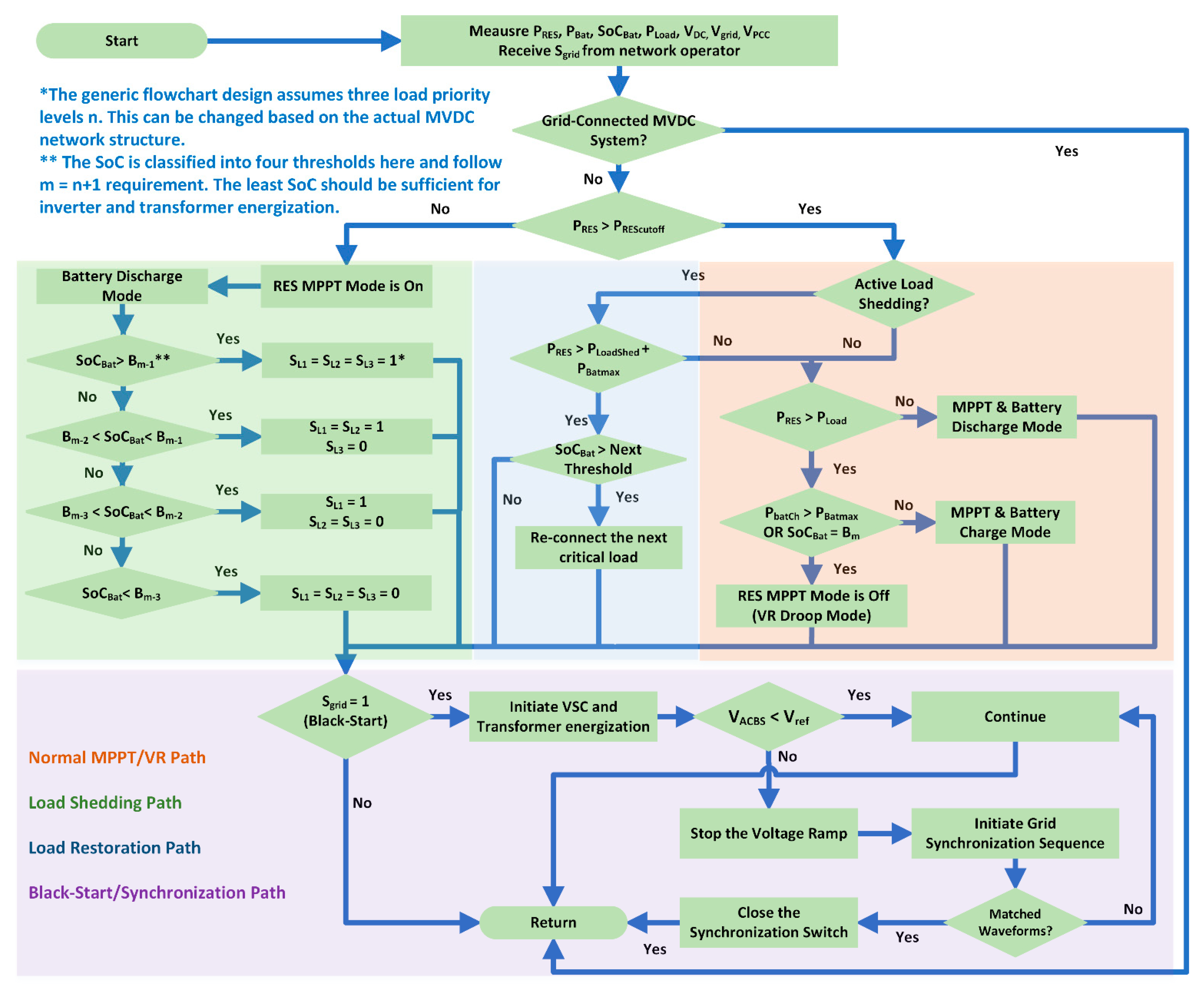
The following section explains the different MVDC network operating modes under the proposed EMS design, where Figure 2 shows a high-level flowchart for the proposed energy management system operation.

3. Proposed EMS Operating Modes

During the MVDC system isolated operation following a grid contingency, the network operates between MPPT and VR modes with load shedding and restoration paths within EMS design as detailed in Section 3.1 and Section 3.2. When the grid restoration signal is received, the black-start and grid synchronization modes of the EMS are activated as explained in Section 3.3. The thresholds defined in Figure 2 are recommended to be designed with small SoC tolerance in both directions to avoid scattered mode switching that may result from RES output intermittency and sudden load variations.

3.1. Maximum Power Point Tracking Modes

The available RES unit operates in MPPT mode when their maximum instantaneous output is not sufficient to cause an over-voltage to the DC bus. For instance, if P R E S > P L o a d , and the storage unit can still be charged (i.e., S o C < S o C m a x ), then the surplus RES power is used to charge the battery. Likewise, RES units should still operate in MPPT mode if P R E S < P L o a d , with the battery operating in its discharge mode to satisfy Equation (2).

3.1.1. Load Shedding Path

If the combined RES output power is consistently below a power cutoff point ( P c u t o f f ) that is defined based on network-specific environmental resources availability and critical load requirements, then the RES units still operate in MPPT mode to extract the maximum power output and the EMS shifts to load shedding operation path.
Once the load shedding path is activated, the remaining load power is supplied by the battery in discharge mode. In this case, clustering the load into different prioritized categories becomes important to maximize the most critical load supply duration. A simplified isolated MVDC network is described here for illustration, where a single offshore wind farm is connected as the power generation source.
If the local wind speed is expected to be below the operating cutoff point for the next x hours, then the local storage should be able to maintain the critical load supply based on its current SoC. The local loads in this case are segmented into n clusters based on their criticality level, while SoC is segmented into m levels between S o C m i n   a n d   S o C m a x , where m = n + 1 . The least critical cluster is disconnected in load shedding path when the SoC falls below the highest segment lower threshold at m 1 , thus elongating the supply period for the remaining load.
If the same condition persists until the SoC reaches m 2 , then the second least-critical load cluster is disconnected. If the weather forecast used to predict the wind farm output has underestimated the plant disconnection period and the SoC eventually falls below the m n level (i.e., S o C m i n ) , then the last resort in this case is for the most critical load to also be temporarily disconnected until the plant generation is restored. Figure 2 demonstrates the load shedding logic for a three load clusters case ( n = 3 ) within the load shedding EMS path. Whereas, Equation (4) illustrates the generic load clustering into n clusters, and Equation (5) mathematically summarizes the load shedding path requirement for each cluster.
P L o a d = S L 1 P L 1 + S L 2 P L 2 + + S L n P L n
S L i s h e d = { 1 : S o C B i 0 : S o C < B i     P R E S < P c u t o f f
where, S L i is the ith load cluster switch, with i ranging from 1 to n, and B i is the lower SoC threshold for the corresponding sector. The lowest SoC sector threshold occurs at B m i n = B 1 = B m n , and the highest SoC sector threshold occurs at B n = B m 1 .

3.1.2. Load Restoration Path

The proposed EMS design only considers load restoration possibility once consistent and sufficient RES power output is accumulated to avoid continuous shedding/restoration modes switching. Based on their availability, weather forecasts (i.e., wind speed, solar irradiance, and temperature) can be additionally used to support the decision-making logic as an adaptive co-factor to load restoration sequence and thresholds definition for increased EMS reliability. If load shedding exists in the network, then battery charging is prioritized, and restoration of the next load cluster is only allowed once the battery is charged to its restoration threshold level. Progressive load reconnection is then carried out as the storage SoC evolves through the defined sectors. Equation (6) summarizes the load restoration path requirements, whereas Figure 2 highlights the path execution within the EMS context.
S L i r e s t o r a t i o n = { 1 : S o C B i 0 : S o C < B i     P R E S > P L o a d s h e d + P B a t m a x
where, P L o a d s h e d is the partial connected load at the considered instant/segment, and i is defined similarly to Equation (5). During this process, the RES units operate in MPPT mode if the required conditions are met, and in VR mode otherwise as explained in the following subsection.

3.2. Voltage Regulation Operating Mode

This mode is activated in one of two cases, either if P R E S > P L o a d and the battery is fully charged, or if the battery is charging at its maximum power P b a t m a x and the charging current is limited by its protective control, which is when P R E S > P L o a d +   P b a t m a x . In either of these cases, the surplus P R E S can cause an overvoltage at the DC bus, and thus shifting the RES units operating mode to VR becomes essential to maintain constant DC bus voltage. Consequently, the battery DC-DC converter control design should consider the overcurrent protection, which can be implemented in many ways, such as dual-loop PI control as illustrated on a high-level in Figure 3.
It should be noted that operation within VR mode is also possible in the load restoration path if the following condition is met: P R E S > P L o a d S h e d + P b a t m a x . This can be considered as a design choice, and is prioritized here compared to direct connection of the shed load before the SoC climbs back to the next segment threshold to avoid scattered mode switching operation (see Figure 2).
Shifting the RES operation mode from MPPT to VR and vice versa for a single RES unit requires shifting the MPPT converter operation point to a new level that stabilizes the DC bus voltage. For instance, if a single PV unit operates in the network, then the DC-DC converter duty ratio D is shifted to a new equilibrium. This can be done using several techniques, such as modified perturb and observe (P&O) [15] or modified voltage reference signal through a switched PI controller [24]. However, power sharing should be considered for multiple RES units. Here, a power sharing technique inspired from droop control is proposed.
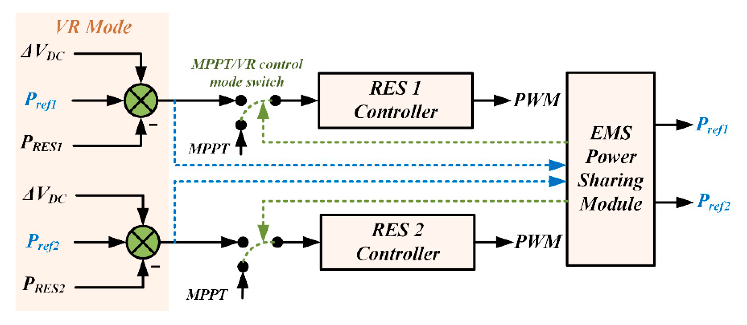
When parallel RES units operate in the isolated MVDC network presented in Figure 1 and a switch to VR mode is required, then different possibilities exist to achieve this requirement, such as shifting the operating point of the largest units only to achieve VR. However, a normalized distribution between the different units is preferred in this case to minimize the impact of large RES unit output intermittency. An analogous principle similar to AC networks droop is considered here. The power reference set-point P r e f V R i of the ith RES unit operating in VR mode is set proportionally to its standard test conditions (STC) rating P S T C . This is mathematically illustrated in Equation (7) for k RES units, thus achieving collaborative, proportional power sharing instead of violent set-point variation of a single unit, where P L o a d refers to the connected load at that instant.
P r e f V R i = { P S T C i i = 1 k P S T C i ( P L o a d + P B a t m a x ) : S o C < S o C m a x P S T C i i = 1 k P S T C i P L o a d                                       : S o C = S o C m a x
To account for possible power mismatches, a supervisory DC bus voltage control is embedded to avoid oversupply and the consequent voltage rise. Namely, if a unit is not able to achieve its new power set-point from Equation (6) due to output shortage, then the EMS instructs the other RES units with higher output availability to increase their power participation for DC bus voltage stabilization. Simultaneously, the power reference is decreased for the units with low output to maintain power balance until environmental conditions allow for proportional sharing again. This is done through imposing converter set-point changes that correspond to DC voltage variations at each generation node through a dynamic EMS power-sharing module.
Figure 4 illustrates the proposed EMS power sharing principle for a simplified case with two RES units. The objective here is to push the VR error to zero for all units through combining the DC VR and the dynamic reference power set-point from Equation (6) to adjust the converter pulse width modulation (PWM) compared to that of MPPT operation. The internal RES controller design depends on the RES type (e.g., solar or wind).

3.3. Black-Start/AC Synchronization Modes

Different network segments may be operated in isolation following large-scale elongated network contingency. Once the issue is alleviated, these segments can be gradually grouped and even used to black-start neighboring areas [32]. In case the investigated MVDC distribution network is required to participate in such black-start scenario upon receiving a request from the utility operator, then it should be ready to energize its AC grid-interfacing assets.
VSCs are interfaced to the grid through three-phase transformer units. Energizing a transformer can result in significant inrush current magnitudes, which can be several time the transformer rated current [33]. VSCs overcurrent capability is far more limited than synchronous generators that have classically been used for transformer energization. Thus, special care should be given when using converters for this task. A transformer inrush current is proportional to its core flux. Flux saturation can thus lead to very high magnetizing (inrush) current. A transformer core flux can be estimated as the integral of winding voltage.
Below, the flux behavior in a transformer core is briefly discussed based on an equivalent single-phase transformer model as in Figure 5, where R1,2 and L1,2 represent the primary and secondary side winding resistance and leakage inductance, respectively, R m and L s a t are the core equivalent resistance and saturation inductance, respectively and i m is the magnetizing current. L s a t is variable in nature and is estimated from the flux-magnetizing current slope, resulting in a very low inductance value in saturation region, and consequently very high magnetizing current.
Assuming negligible L 1 and very high R m values for simplification, and considering that the secondary side is open-circuit during energization, the core flux ϕ can be estimated as in Equation (8) from [34], where ϕ r is the residual core flux following previous de-energization, and α is the voltage angle at the energization instant.
ϕ L s a t V p cos ( ω t + α ) R 1 2 + ( ω L s a t ) 2 + ( ϕ r + L s a t V p cos ( α ) R 1 2 + ( ω L s a t ) 2 ) e R 1 L s a t t
The first term in Equation (8) represents the oscillatory steady state, unsaturated, flux value. For the considered single-phase transformer model, it can be observed that random energizing, for instance at α = 0, would result in a maximum flux value during the first cycle that creates a high magnitude inrush current that can well-exceed the power electronic converter rating. Equivalent observations apply to three-phase transformers with variations that depend on the used topology. This example illustrates the necessity of investigating alternative options for VSC based transformer energization within the proposed EMS design. In this case, soft transformer voltage ramping is used as detailed below.
Collectively, the EMS design takes into account the outlined black-start and grid synchronization requirements by adopting the following steps:
(a)
Always maintaining a minimum battery SoC during isolated MVDC operation, where S o C m i n definition should be set based on network planning and contracted capacity with the utility.
(b)
Applying modified grid-forming control to the interface converter with ramping voltage reference V A C r e f between 0 and 1 pu between time t = 0 and T r a m p to gradually energize the connected network’s AC transformer and avoid inrush current flow. Equation (9) defines the ramping AC voltage V A C B S requirement. The ramping time T r a m p is set in accordance with transformer parameters, such as the residual flux and damping time constant to avoid saturation at lower ramping times.
| V A C B S | = { t T r a m p | V g r i d | : t < T r a m p | V g r i d |             : t > T r a m p
(c)
Matching the AC voltage magnitude, frequency, and phase to the neighboring energized AC network before synchronizing both areas. A common synchronizing requirement from IEEE is summarized in [35]. For further protection, an additional switch is added S E n a b l e that is monitored and manually set to 1 when synchronization conditions are achieved before closing the STS as defined in Equation (10).
S T S c l o s e = { 1     | V g r i d | δ V | V P C C | | V g r i d | + δ V f g r i d δ f f d s f g r i d + δ f θ g r i d δ θ θ d s θ g r i d + δ θ   &   S E n a b l e = 1
where δ V , f , θ indicate the grid-code defined reconnection margin for voltage magnitude, frequency, and phase angle, respectively, and the d s subscript denotes the MVDC distribution system.
Figure 6 summarizes the high-level EMS control for this operating mode, which is activated when S g r i d = 1 from Figure 2. Initially, the ramping voltage reference is applied from 0 to 1 pu in T r a m p and the converter operates in grid-forming mode. The voltage is measured before and after the grid connection point. A phase-locked-loop (PLL) is used to extract the frequency and phase angles. The latter is matched between both voltages by applying a gradual shift the digital V A C r e f signal. When synchronization conditions are satisfied and S E n a b l e is manually changed to 1, then the STS switch closes and the converter shifts to the grid-following PQ operating mode.
A mode switch from grid forming to grid-following is advisable only if the synchronized network is strong enough to sustain reliable PLL reference. Alternatively, more robust grid-forming modes can also be implemented to provide simultaneous grid-support and PQ reference tracking as explained in [36,37].

4. Proposed EMS Design Verification: Case Studies

This section presents two case studies with results illustrating the EMS robustness under different operating conditions and scenarios using simulated models and a scaled experimental laboratory setup. The first case study is simulation-based using MATLAB/Simulink, and is designed to test different EMS operating stages with two solar PV resources and DC switched loads to test the power-sharing VR functionality, soft transformer start with auxiliary AC loads supply, in addition to grid synchronization. The second case study is experimental using a scaled down laboratory setup, and it aims to verify the proposed EMS operation in its main modes using relevant hardware configuration. Table 1 summarizes the tests and their objectives.
All of the used converters in the simulation study are assumed here to have ideal components and are built in MATLAB/Simulink using average model assumptions. In practice, conventional DC–DC converters, for instance, such as boost type have limited gain due to their switching losses and parasitic elements at higher duty ratios. Different topologies are presented in literature to maximize the gain, such as cascading different stages or using isolated converters, and the topology selection depends on the required gain, efficiency and application requirements. Detailed consideration of such topologies can be found in [38,39,40].
In both simulation and experimental tests, the perturb and observe (P&O) MPPT technique is used for PV DC–DC converters, with a modified duty ratio perturbation logic to achieve VR under shifted operation mode. The solar PV systems are simulated using the single-diode model. Dual loop PI is used for the battery (Figure 3), and the control structure in Figure 5 is used for the AC system black-start/synchronization tests. For the experimental DC–AC converter control, dual-loop direct-quadrature (dq) control is used. The outer loop in grid-forming mode generates dq current references through digitally synthesized, scaled, 50 Hz siunsoid reference tracking using PI controllers, whereas in grid-following mode, the current references are generated from PQ reference tracking. Sinusoid pulse width modulation (SPWM) is implemented to drive the controller (see Figure 6).
The simulated three-phase Δ / Y transformer is based on the default parameters of MATLAB/Simulink saturable model, scaled to the system rating. Detailed converter control design is beyond the scope of this work, and comprehensive reviews are selected for further reading on solar [41,42] and wind [43] converters control. Finally, it should be noted that the EMS can operate with different device-level controllers as it mainly operates as a secondary level control structure, adding more user design flexibility.

4.1. Case Study 1: EMS Test with Multiple RES Units (Power Sharing)

The test network in this case study is composed of two parallel-operated PV farms, interfaced to the DC bus through boost DC-DC converters, and the battery is interfaced to the DC bus through a bidirectional boost converter. The connected loads are divided into three priority clusters (n = 3) and controlled through separate switches SL1 to SL3. The SoC thresholds (m = 4) are selected to be at 100%, 70%, 50%, and 20%, where the latter is assumed the minimum network requirement to guarantee a successful black-start in case of zero RES output at that instant to support auxiliary AC loads. The AC system interfacing is performed using a two-level three-phase voltage source converter via a three-phase transformer. Figure 7 shows the configuration used for the EMS simulated tests. From the three parallel-connected DC–DC converters in isolated mode, the battery bidirectional converter is responsible for maintaining DC bus voltage, and its charge/discharge operation depends on the power balance defined in Equation (2) to maintain reliable connected load supply. Similarly, the two uni-directional PV converters operate either in MPPT or VR mode based on the set of constraints defined in Figure 2. In VR mode, the control of both converters is modified to achieve proportional, droop like, power sharing as described in Figure 4.
Key simulated system parameters are summarized in Table 2. The designed ratings and parameters are selected to reflect a medium-power network with a generation capacity exceeding local loads for power export under grid-connected conditions. This is to verify MPPT-VR transitions during the MVDC distribution network isolated operation when excess power cannot be exported to the grid.

4.1.1. RES Mode Shift and Power Sharing Test

In this simulated scenario, load-shedding conditions are not met and thus the proposed EMS operates in the main path from Figure 2. Initially, the irradiance is set to 600   W / m 2 . In this case, both PV systems operate in MPPT and collectively output 12 MW, while the total connected load is 6 MW, and thus the battery is charged with the excess 6 MW. The irradiance is then increased to 700   W / m 2 with P R E S = 14   MW and the MPPT mode persists since the condition P R E S < P L o a d + P b a t m a x is still satisfied. However, when the irradiance is increased to 800 W / m 2 , then the PV output becomes at the MPPT-VR modes barrier as it approaches 15 MW. More evidently, an irradiance of 900   W / m 2 would have resulted in P R E S around 18 MW if MPPT persisted. Figure 8a demonstrates these results through averaged simulations and illustrates that in this case VR mode forces the power sharing functionality to adjust both PV operating points according to Equation (6), forcing PV1 and PV2 to collectively operate around 15 MW. This shift requires modifying the operating point on the PV curve. Figure 8a illustrates this shift between t = 3 to 5 s in the voltage and current for PV1. That is, irradiance increments in solar PV mainly increases the power through current increments with minimal voltage impact, whereas the voltage between t = 3 to 5 s is noticeably decreased to counter current increment thus drifting away from the maximum power to achieve VR and maintain constant DC voltage.

4.1.2. Load Shedding/Restoration Test

For this test, the battery SoC is initially set slightly above 50%, with the irradiance set to zero to simulate a case when the least critical load cluster is already disconnected because SoC < 70% with insufficient RES output. The total connected load at the beginning of the simulation is thus 4 MW, fully supplied by the battery, and the proposed EMS operates following the load shedding path. At t = 1, SoC falls below 50%, and the second load cluster is disconnected to prolong the supply period of the most critical load cluster. On the other hand, the PV systems are switched on at t = 2 with an irradiance pump from 0 to 700   W / m 2 . The collective output power from PV1 and PV2 is initially used to charge the battery until it exceeds its maximum power then the rest will be supplied to the total connected load (Figure 8b). The shedding load cluster can be reconnected through the load restoration path once the battery SoC exceeds 50% again. This sequence is recommended to accelerate the battery SoC buildup.
The least critical load cluster can only be reconnected once SoC exceeds 70%. Figure 8b illustrates the results of this test, where it can be observed that the DC bus voltage is maintained nearly constant during this process. Clearly, the used timescales here are exaggerated to cover different modes and do not necessarily reflect actual ramping times for similarly rated assets.

4.1.3. Black-Start/Transformer Energization

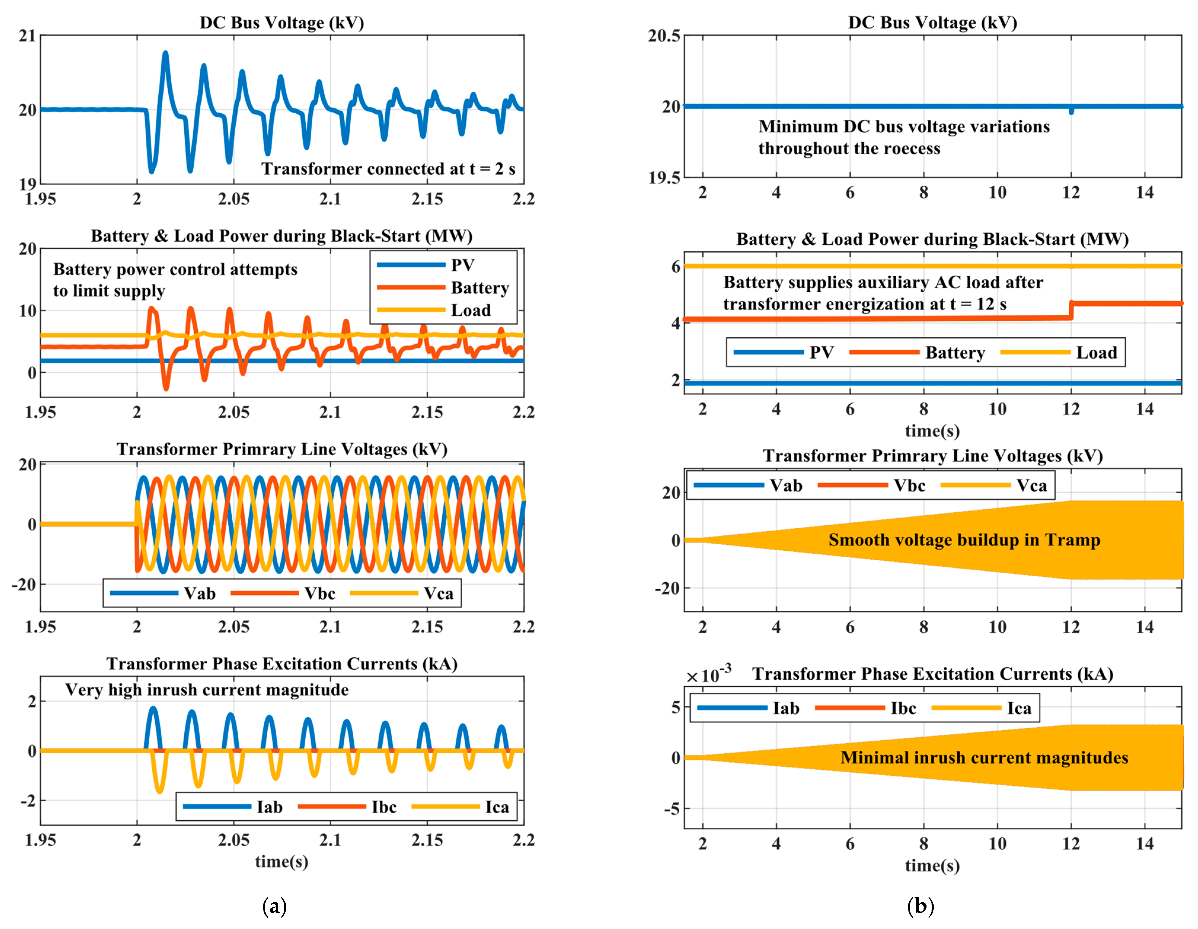
The black-start route in Figure 2 is subject to receiving a restoration signal from the network operator, and the existence of a minimal SoC in the battery storage. When both conditions are satisfied, a successful black-start participation is feasible by the proposed EMS. The test presented in this section first demonstrates the issue of using hard transformer energization and its negative interactions with the proposed EMS, and then illustrates the soft transformer startup as a feasible solution. The PV systems are operated at low irradiance that is selected to be just above the cutoff power for this design ( 100   W / m 2   around   2   MW ) to avoid falling into the shedding/restoration path. This relatively low power is also selected to better visualize the battery and DC bus voltage interactions with AC side during black-start. Simultaneously, the load is fully connected (normal operating path, Figure 2) and the battery supplies 4 MW of the total 6 MW demand. As illustrated in Figure 9a, the black-start signal is received from utility at t = 2, and the converter is energized with a 1 pu voltage instantly, which is simultaneously applied at the transformer and the AC auxiliary load terminals (see Figure 7). In Figure 9a, the converter current control is disconnected, to demonstrate the unrestricted sourced inrush current through the converter while operating in AC voltage control mode.
Very high current pulses in kilo-amperes are generated at the saturated transformer cores, resulting in violent DC link voltage and battery power variations to generate/absorb this inrush power. On the other hand, energizing the same transformer through soft start with T r a m p = 10   s according to Equation (9) resulted in a smooth operation as illustrated in Figure 9b. In this case, the gradual voltage buildup effectively eliminates inrush current, stabilizes the DC link voltage, and only consumes small additional battery power to supply the 0.5 MW auxiliary AC load as compared to Figure 9a, demonstrating clear advantages for the soft transformer start selection within the proposed EMS design.

4.1.4. Grid Synchronization Test

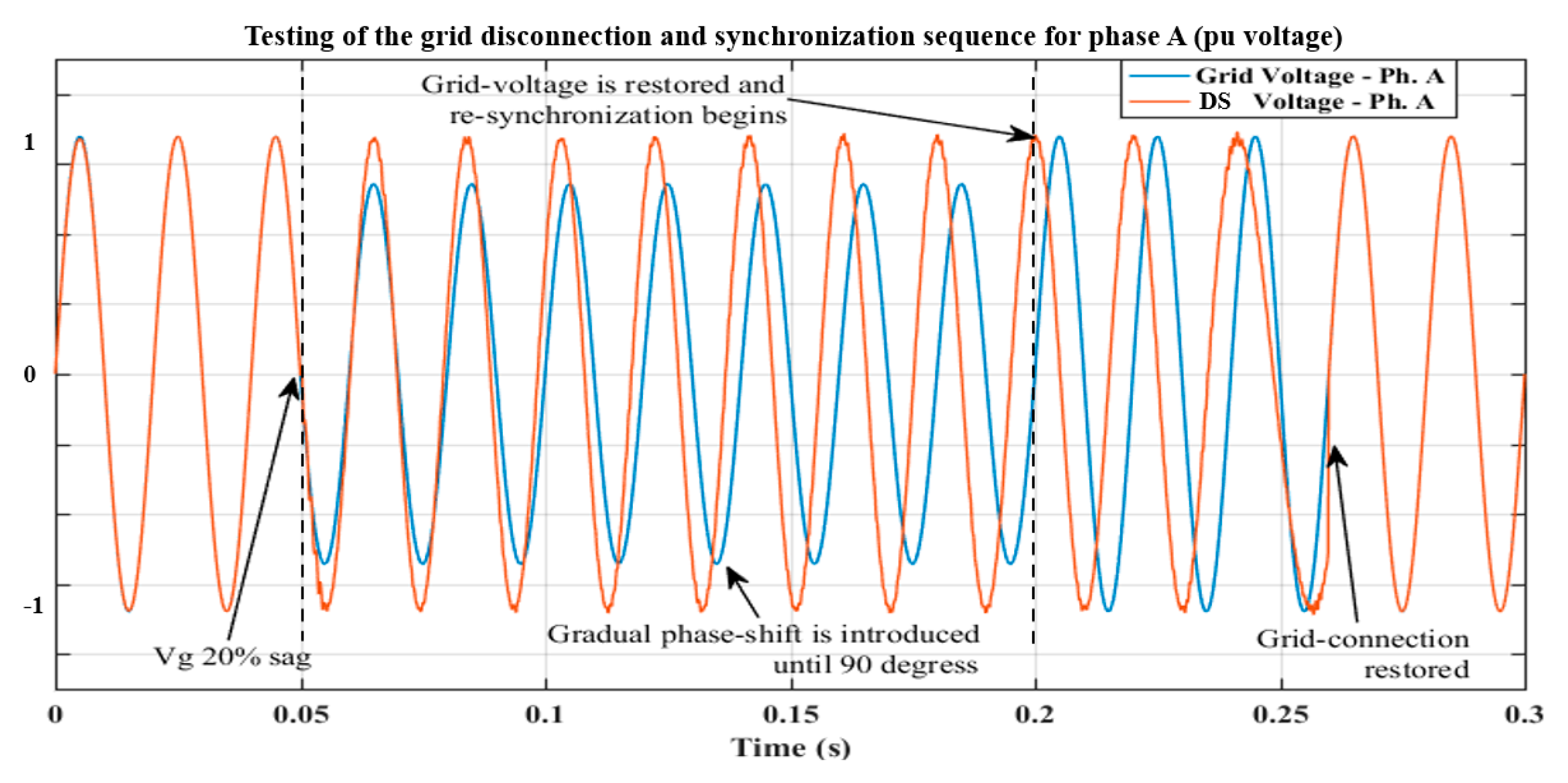
After transformer energization, the voltage at the PCC needs to be synchronized with the utility grid before closing the breakers to avoid causing short circuits. This requires matching the voltage magnitude, frequency, and phase as explained in Section 3.3. This test expands on that and illustrates the process in both directions, starting from grid disconnection to grid reconnection. Figure 10 shows the result for phase A of the synchronizing MVDC distribution system (DS) and grid voltages. At t = 0.05 s, a fault occurs causing the DS to instantly shift from grid-following to grid-forming control. To showcase the resynchronization process, a gradual 90 degrees phase shift is first introduced between both voltages, and at t = 0.2 s, the grid voltage is restored (contingency resolved). However, the DS converter still operates in grid-forming mode due to the existing 90 degrees phase shift. The DS voltage reference is then similarly adjusted to eliminate phase error Δ θ (see Figure 6) using a PLL output matching technique with PI compensators. Around t = 0.265 s, the synchronization requirements are satisfied again, the synchronization switch is closed and the DS converter seamlessly shifts back to grid-following control mode.

4.2. Case Study 2: Proposed EMS Experimental Verification

The proposed EMS functionalities are experimentally verified using a scaled down microgrid lab setup. The setup consists of a flexible and controllable grid, load, and battery emulators from CINERGIA, and a TerraSAS PV emulator. The network unidirectional and bidirectional DC–DC boost converters, and the three-phase DC–AC converter are controlled through a dedicated dSPACE SCALEXIO interface fully developed by the authors. Figure 11a illustrates the setup layout block diagram.
The setup is similar to that used for the simulated case study 1, with the difference being the existence of a single PV source emulator and no grid interface transformer, thus presenting complimentary test scenarios to those presented in simulation. Figure 11b shows the physical setup and controller connections.
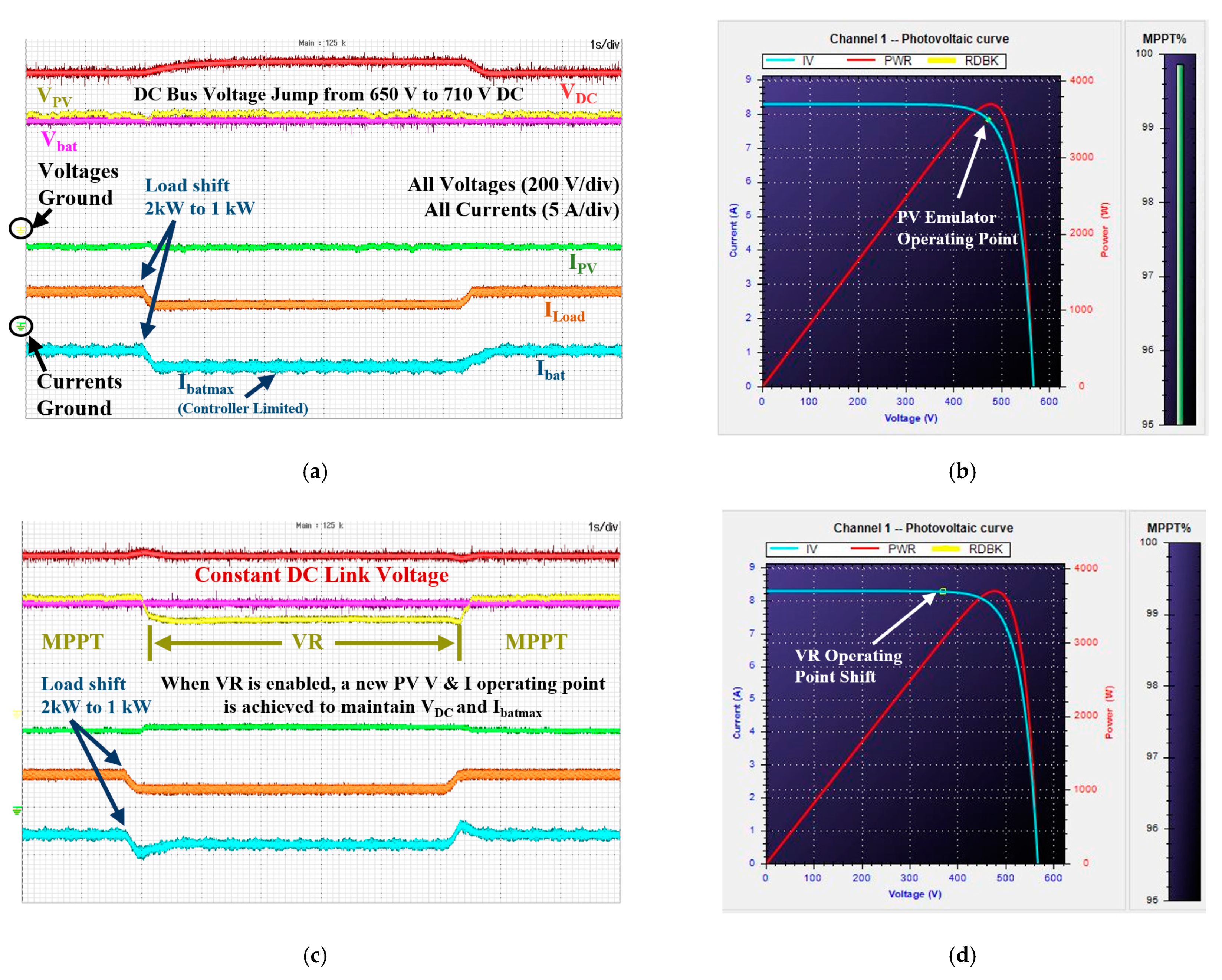
The conducted tests aimed at experimentally verifying the RES mode shift in response to load changes vs. an operation case without active EMS in the isolated network operation mode, in addition to the grid synchronization functionalities. Experimental test parameters are summarized in Table 3.

4.2.1. Proposed EMS Experimental Voltage Regulation Test

The simulated analogous test verified the proposed EMS operation against irradiance variations and to achieve power sharing, whereas the tests performed here expand on different scenarios that include low loading conditions to cover more operating possibilities within the manuscript span. First, the issue of operating the network with no active EMS under this mode is experimentally illustrated. Namely, the PV is initially operating in MPPT mode with a 3.6 kW output, against a 2 kW connected DC load with the surplus power used to charge the battery. PBatma is defined around 2.2 kW, with Vbat = 450 V. Figure 12 illustrates the results of this test. At t = 2 s, the rated load is reduced to 1 kW and back to 2 kW at t = 7.25 s. Between these two points, the PV remains operating at MPPT, the excess power is fed to the battery until PBatmax is reached. The surplus power can only then be forced into the load as in Equation (11), increasing its voltage and consumption, and risking damaging it.
P s u r p l u s = ( V D C n e w 2 V D C n o m i n a l 2 Z L o a d ) = ( P M P P T P B a t m a x P L o a d r a t e d P L o s s e s )
where, P L o a d r a t e d is the rated load power and P L o s s e s are the system power losses.
On the other hand, when the proposed EMS is activated, then the rated load shift from 2 kW to 1 kW is met with a shift in RES operating mode, as illustrated in Figure 12c,d, to preserve DC bus voltage by adjusting the PV emulator set-point with lower voltage and slightly higher current, effectively reducing the PV output from 3.6 kW to 3 kW. Similarly, the PV operating point is shifted again to MPPT when the rated load power is stepped back to 2 kW.

4.2.2. Grid Synchronization Test

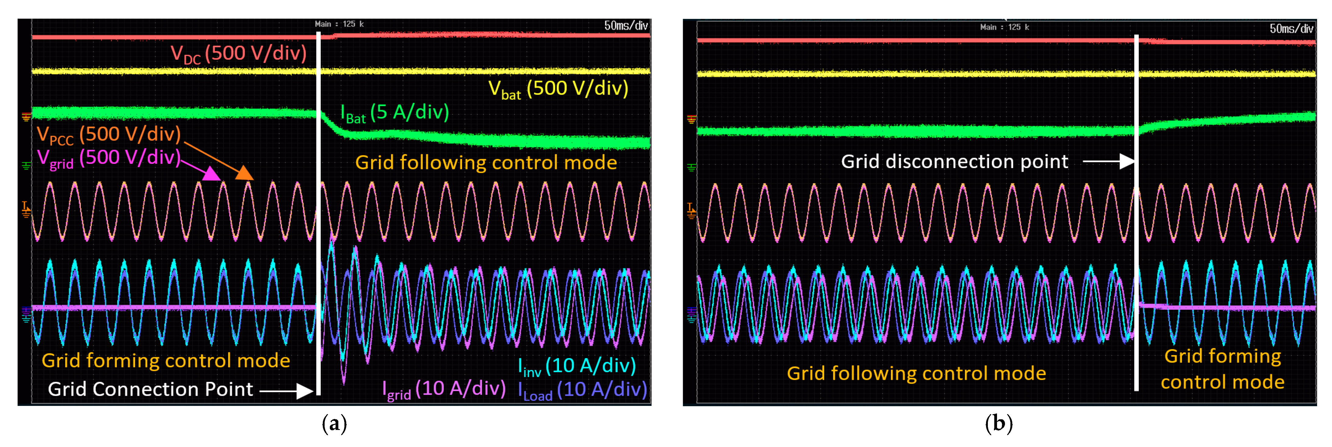
The experimental setup is also used to verify the grid synchronization sequence of the proposed EMS by matching the converter voltage parameters to the grid voltage. Similar to the simulated case, the DC bus current is fed by the battery through its bidirectional boost converter, and the three-phase converter is operated in grid-forming mode as illustrated in Figure 13. In this scenario, an AC load is connected to demonstrate the proposed EMS adaptability to different isolated systems. The AC load is fed by the converter output current ( I i n v ) , and once the voltage waveforms are matched, the synchronization signal is issued at the grid-connection point, and the converter control mode immediately shifts to grid-following operation. The AC current transients in Figure 13a are a result of operating point shift in grid-following mode to test the controller robustness. The AC load is initially 3 kW, and in grid-following mode, the new reference points were set to P r e f = 1.5   kW   and   Q r e f = 2   kVAR , with the shortage immediately supplied by the grid, and the battery current reduced because of the grid taking over part of the AC load supply. Conversely, the network disconnection is also tested for the same set-points in Figure 13b, with the distribution system converter immediately shifting its operation back to grid-forming mode and supplying the load demand. Collectively, the test illustrates the synchronization technique effectiveness based on Figure 6, and the control robustness in shifting between different modes with minimal load supply disruptions.

5. Conclusions

This paper proposed a new energy management system for MVDC networks with black-start capabilities to preserve the operation of an isolated MVDC network in a post-elongated contingency scenario, and to maintain its black-start readiness. The proposed EMS is comprehensively designed to cover various operating paths to achieve these targets. The issue of power oversupply and overvoltage violations in isolated systems is addressed through proposing mode shifts in RES set-points to participate in voltage regulation (VR) when required instead of continuously operating in MPPT. A power sharing strategy has been proposed to proportionally distribute the power between different RES units in VR mode. The proposed EMS design is agnostic to the generation source type and can operate different assets such as wind turbines and solar PV. Moreover, an innovative partial load shedding and restoration strategy with load prioritizing and clustering have been presented to overcome undersupply conditions and prolong the supply duration of critical load assets. Minimum battery SoC requirements are presented to support black-start readiness. Soft transformer energization was compared to hard energization and is shown to be more reliable in eliminating inrush currents that could jeopardize system operation during black-start. Grid synchronization strategy and design considerations are also presented. Simulation and experimental results have confirmed all aforementioned points with performance evaluations and practical design recommendations. The EMS design operates on a secondary control level, allowing for more flexibility on the primary level control of different devices based on the application requirements (e.g., PI, sliding mode, model predictive control, etc.).
Possible improvements to the EMS design can be to integrate load and weather forecasting with artificial intelligence to increase the decisions reliability on the load clustering and SoC thresholds definition. Moreover, distributed storage units coordination and SoC management can be an interesting research path to improve the EMS design in larger networks.

Author Contributions

Conceptualization, A.A. and O.E.; methodology, A.A.; software, A.A.; validation, A.A. and O.E. formal analysis, A.A.; investigation, A.A.; writing—original draft preparation, A.A.; writing—review and editing, A.A., K.A., and A.E.-À.; visualization, A.A.; supervision, K.A., A.E.-À., and O.E. All authors have read and agreed to the published version of the manuscript.

Funding

This research received no external funding.

Data Availability Statement

Not Applicable.

Acknowledgments

This publication is supported by Iberdrola S.A. as part of its innovation department research activities. Its contents are solely the responsibility of the authors and do not necessarily represent the official views of Iberdrola Group.

Conflicts of Interest

The authors declare no conflict of interest.

References

  1. Henbest, S. New Energy Outlook 2019; Bloomberg New Energy Finance: New York, NY, USA, 2019. [Google Scholar]
  2. Alassi, A.; Bañales, S.; Ellabban, O.; Adam, G.; MacIver, C. HVDC Transmission: Technology Review, Market Trends and Future Outlook. Renew. Sustain. Energy Rev. 2019, 112, 530–554. [Google Scholar] [CrossRef]
  3. Zhang, S.; Zhou, M.; Li, G. Applying power margin tracking droop control to flexible operation of renewables generation multi-terminal DC collector system. CSEE J. Power Energy Syst. 2020, 1–10. [Google Scholar] [CrossRef]
  4. Siddique, H.A.B.; Doncker, R.W.D. Evaluation of DC Collector-Grid Configurations for Large Photovoltaic Parks. IEEE Trans. Power Deliv. 2018, 33, 311–320. [Google Scholar] [CrossRef]
  5. Chuangpishit, S.; Tabesh, A.; Moradi-Shahrbabak, Z.; Saeedifard, M. Topology Design for Collector Systems of Offshore Wind Farms with Pure DC Power Systems. IEEE Trans. Ind. Electron. 2014, 61, 320–328. [Google Scholar] [CrossRef]
  6. MVDC Plus: Medium Voltage Direct Current Managing the Future Grid; Siemens: Munich, Germany, 2017.
  7. Steinke, J.K.; Maibach, P.; Ortiz, G.; Canales, F.; Steimer, P. MVDC Applications and Technology. In Proceedings of the PCIM Europe 2019 International Exhibition and Conference for Power Electronics, Intelligent Motion, Renewable Energy and Energy Management, Nuremberg, Germany, 7–9 May 2019; pp. 1–8. [Google Scholar]
  8. Yu, J.; Smith, K.; Urizarbarrena, M.; Bebbington, M.; Macleod, N.; Moon, A. Initial designs for ANGLE-DC project: Challenges converting existing AC cable and overhead line to DC operation. CIRED Open Access Proc. J. 2017, 2017, 2374–2378. [Google Scholar] [CrossRef] [Green Version]
  9. Hunter, L.; Booth, C.; Ferre, A.J.; Finney, S. MVDC for enhanced utility scale distribution power delivery and control. In Proceedings of the 2017 52nd International Universities Power Engineering Conference (UPEC), Heraklion, Greece, 28–31 August 2017; pp. 1–6. [Google Scholar]
  10. Aki, H. Demand-Side Resiliency and Electricity Continuity: Experiences and Lessons Learned in Japan. Proc. IEEE 2017, 105, 1443–1455. [Google Scholar] [CrossRef]
  11. Marnay, C.; Aki, H.; Hirose, K.; Kwasinski, A.; Ogura, S.; Shinji, T. Japan’s Pivot to Resilience: How Two Microgrids Fared after the 2011 Earthquake. IEEE Power Energy Mag. 2015, 13, 44–57. [Google Scholar] [CrossRef]
  12. Kumar, J.; Agarwal, A.; Singh, N. Design, operation and control of a vast DC microgrid for integration of renewable energy sources. Renew. Energy Focus 2020, 34, 17–36. [Google Scholar] [CrossRef]
  13. Augustine, S.; Mishra, M.K.; Lakshminarasamma, N. A Unified Control Scheme for a Standalone Solar-PV Low Voltage DC Microgrid System with HESS. IEEE J. Emerg. Sel. Top. Power Electron. 2020, 8, 1351–1360. [Google Scholar] [CrossRef]
  14. Sahoo, S.; Mishra, S.; Jha, S.; Singh, B. A Cooperative Adaptive Droop Based Energy Management and Optimal Voltage Regulation Scheme for DC Microgrids. IEEE Trans. Ind. Electron. 2020, 67, 2894–2904. [Google Scholar] [CrossRef]
  15. Alassi, A.; Ellabban, O. Design of an Intelligent Energy Management System for Standalone PV/Battery DC Microgrids. In Proceedings of the 2019 2nd International Conference on Smart Grid and Renewable Energy (SGRE), Doha, Qatar, 19–21 November 2019; pp. 1–7. [Google Scholar]
  16. Dos Santos Neto, P.J.; dos Santos Barros, T.A.; Silveira, J.P.C.; Filho, E.R.; Vasquez, J.C.; Guerrero, J.M. Power Management Strategy Based on Virtual Inertia for DC Microgrids. IEEE Trans. Power Electron. 2020, 35, 12472–12485. [Google Scholar] [CrossRef]
  17. Marín, L.G.; Sumner, M.; Muñoz-Carpintero, D.; Köbrich, D.; Pholboon, S.; Sáez, D.; Núñez, A. Hierarchical Energy Management System for Microgrid Operation Based on Robust Model Predictive Control. Energies 2019, 12, 4453. [Google Scholar] [CrossRef] [Green Version]
  18. Vásquez, L.O.P.; Ramírez, V.M.; Thanapalan, K. A Comparison of Energy Management System for a DC Microgrid. Appl. Sci. 2020, 10, 1071. [Google Scholar] [CrossRef] [Green Version]
  19. Benlahbib, B.; Bouarroudj, N.; Mekhilef, S.; Abdeldjalil, D.; Abdelkrim, T.; Bouchafaa, F.; lakhdari, A. Experimental investigation of power management and control of a PV/wind/fuel cell/battery hybrid energy system microgrid. Int. J. Hydrog. Energy 2020, 45, 29110–29122. [Google Scholar] [CrossRef]
  20. Dos Santos Neto, P.J.; Barros, T.A.S.; Silveira, J.P.C.; Ruppert Filho, E.; Vasquez, J.C.; Guerrero, J.M. Power management techniques for grid-connected DC microgrids: A comparative evaluation. Appl. Energy 2020, 269, 115057. [Google Scholar] [CrossRef]
  21. Matayoshi, H.; Kinjo, M.; Rangarajan, S.S.; Ramanathan, G.G.; Hemeida, A.M.; Senjyu, T. Islanding operation scheme for DC microgrid utilizing pseudo Droop control of photovoltaic system. Energy Sustain. Dev. 2020, 55, 95–104. [Google Scholar] [CrossRef]
  22. Batiyah, S.; Sharma, R.; Abdelwahed, S.; Zohrabi, N. An MPC-based power management of standalone DC microgrid with energy storage. Int. J. Electr. Power Energy Syst. 2020, 120, 105949. [Google Scholar] [CrossRef]
  23. Liu, B.; Zhuo, F.; Zhu, Y.; Yi, H. System Operation and Energy Management of a Renewable Energy-Based DC Micro-Grid for High Penetration Depth Application. IEEE Trans. Smart Grid 2015, 6, 1147–1155. [Google Scholar] [CrossRef]
  24. Mirzaei, A.; Forooghi, M.; Ghadimi, A.A.; Abolmasoumi, A.H.; Riahi, M.R. Design and construction of a charge controller for stand-alone PV/battery hybrid system by using a new control strategy and power management. Sol. Energy 2017, 149, 132–144. [Google Scholar] [CrossRef]
  25. Cai, H.; Xiang, J.; Wei, W. Decentralized Coordination Control of Multiple Photovoltaic Sources for DC Bus Voltage Regulating and Power Sharing. IEEE Trans. Ind. Electron. 2018, 65, 5601–5610. [Google Scholar] [CrossRef]
  26. Chowdhury, N.; Pilo, F.; Pisano, G. Optimal Energy Storage System Positioning and Sizing with Robust Optimization. Energies 2020, 13, 512. [Google Scholar] [CrossRef] [Green Version]
  27. Ellabban, O.; Alassi, A. Optimal hybrid microgrid sizing framework for the mining industry with three case studies from Australia. IET Renew. Power Gener. 2021, 15, 409–423. [Google Scholar] [CrossRef]
  28. Wei, J.; Zhang, Y.; Wang, J.; Cao, X.; Khan, M.A. Multi-period planning of multi-energy microgrid with multi-type uncertainties using chance constrained information gap decision method. Appl. Energy 2020, 260, 114188. [Google Scholar] [CrossRef]
  29. Cui, H.; Li, F.; Fang, X.; Chen, H.; Wang, H. Bilevel Arbitrage Potential Evaluation for Grid-Scale Energy Storage Considering Wind Power and LMP Smoothing Effect. IEEE Trans. Sustain. Energy 2018, 9, 707–718. [Google Scholar] [CrossRef]
  30. Shim, J.W.; Verbič, G.; Zhang, N.; Hur, K. Harmonious Integration of Faster-Acting Energy Storage Systems into Frequency Control Reserves in Power Grid with High Renewable Generation. IEEE Trans. Power Syst. 2018, 33, 6193–6205. [Google Scholar] [CrossRef]
  31. Chang, W.-Y. The State of Charge Estimating Methods for Battery: A Review. ISRN Appl. Math. 2013, 2013, 953792. [Google Scholar] [CrossRef]
  32. Pagnani, D.; Blaabjerg, F.; Bak, C.L.; da Faria Silva, F.M.; Kocewiak, Ł.H.; Hjerrild, J. Offshore Wind Farm Black Start Service Integration: Review and Outlook of Ongoing Research. Energies 2020, 13, 6286. [Google Scholar] [CrossRef]
  33. Black Start from Non-Traditional Generation Technologies; National Grid: London, UK, 2019.
  34. Mitra, J.; Xu, X.; Benidris, M. Reduction of Three-Phase Transformer Inrush Currents Using Controlled Switching. IEEE Trans. Ind. Appl. 2020, 56, 890–897. [Google Scholar] [CrossRef]
  35. Ashabani, M.; Freijedo, F.D.; Golestan, S.; Guerrero, J.M. Inducverters: PLL-Less Converters with Auto-Synchronization and Emulated Inertia Capability. IEEE Trans. Smart Grid 2016, 7, 1660–1674. [Google Scholar] [CrossRef]
  36. Tayyebi, A.; Groß, D.; Anta, A.; Kupzog, F.; Dörfler, F. Frequency Stability of Synchronous Machines and Grid-Forming Power Converters. IEEE J. Emerg. Sel. Top. Power Electron. 2020, 8, 1004–1018. [Google Scholar] [CrossRef] [Green Version]
  37. Matevosyan, J.; Badrzadeh, B.; Prevost, T.; Quitmann, E.; Ramasubramanian, D.; Urdal, H.; Achilles, S.; MacDowell, J.; Huang, S.H.; Vital, V.; et al. Grid-Forming Inverters: Are They the Key for High Renewable Penetration? IEEE Power Energy Mag. 2019, 17, 89–98. [Google Scholar] [CrossRef]
  38. Alassi, A.; Massoud, A. High-gain DC-DC converters for high-power PV applications: Performance assessment. In Proceedings of the 2018 IEEE 12th International Conference on Compatibility, Power Electronics and Power Engineering (CPE-POWERENG), Doha, Qatar, 10–12 April 2018; pp. 1–6. [Google Scholar]
  39. Alassi, A.; Al-Aswad, A.; Gastli, A.; Brahim, L.B.; Massoud, A. Assessment of Isolated and Non-Isolated DC-DC Converters for Medium-Voltage PV Applications. In Proceedings of the 2017 9th IEEE-GCC Conference and Exhibition (GCCCE), Manama, Bahrain, 8–11 May 2017; pp. 1–6. [Google Scholar]
  40. Denniston, N.; Massoud, A.M.; Ahmed, S.; Enjeti, P.N. Multiple-Module High-Gain High-Voltage DC–DC Transformers for Offshore Wind Energy Systems. IEEE Trans. Ind. Electron. 2011, 58, 1877–1886. [Google Scholar] [CrossRef]
  41. Murillo-Yarce, D.; Alarcón-Alarcón, J.; Rivera, M.; Restrepo, C.; Muñoz, J.; Baier, C.; Wheeler, P. A Review of Control Techniques in Photovoltaic Systems. Sustainability 2020, 12, 10598. [Google Scholar] [CrossRef]
  42. Mao, M.; Cui, L.; Zhang, Q.; Guo, K.; Zhou, L.; Huang, H. Classification and summarization of solar photovoltaic MPPT techniques: A review based on traditional and intelligent control strategies. Energy Rep. 2020, 6, 1312–1327. [Google Scholar] [CrossRef]
  43. Ghaffarzadeh, H.; Mehrizi-Sani, A. Review of Control Techniques for Wind Energy Systems. Energies 2020, 13, 6666. [Google Scholar] [CrossRef]
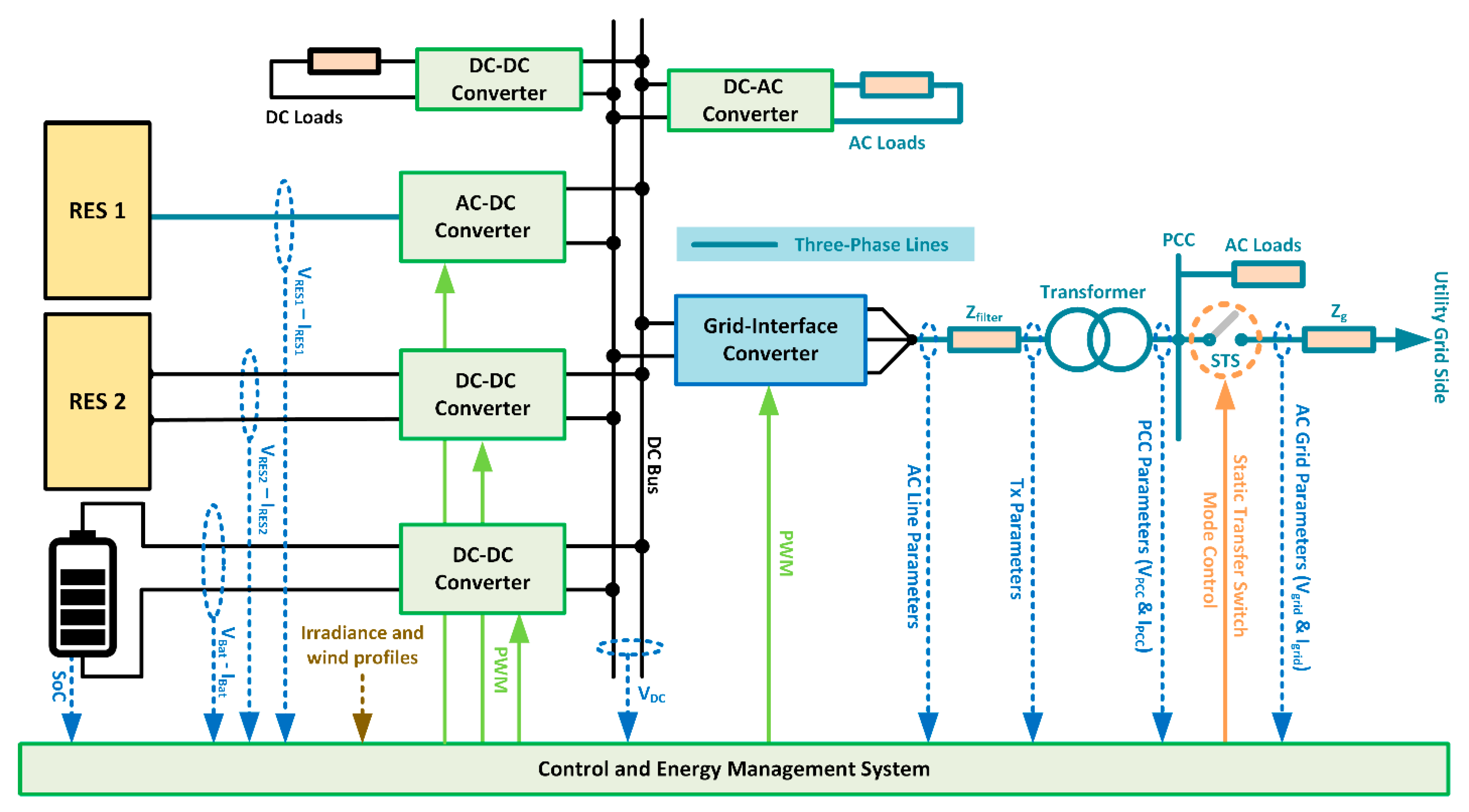
Figure 1. High-level block diagram for a generic MVDC distribution network and its AC grid interface.
Energies 14 02100 g001
Figure 2. Detailed energy management system (EMS) design flowchart with multiple operating modes.
Energies 14 02100 g002
Figure 3. Battery DC–DC converter control with inner overcurrent protection.
Energies 14 02100 g003
Figure 4. Multiple renewable energy sources (RES) units power sharing control in the EMS VR mode.
Energies 14 02100 g004
Figure 5. Electrical model for a single-phase transformer.
Energies 14 02100 g005
Figure 6. High-level EMS control design for AC black-start and synchronization operating modes.
Energies 14 02100 g006
Figure 7. Test network used for case study 1 with key parameters.
Energies 14 02100 g007
Figure 8. Simulation results for the isolated MVDC Distribution System (DC Side): (a) MPPT–VR–MPPT mode shift to maintain constant DC link voltage, (b) load shedding and restoration sequence illustration.
Energies 14 02100 g008
Figure 9. Simulation results for the EMS black-start sequence (AC Side): (a): hard transformer energization, (b): soft transformer energization (voltage ramping).
Energies 14 02100 g009
Figure 10. Grid disconnection/re-synchronization sequence.
Energies 14 02100 g010
Figure 11. Experimental microgrid verification setup: (a) layout block diagram, (b) physical setup.
Energies 14 02100 g011
Figure 12. Experimental MPPT–VR–MPPT mode shift validation for the designed EMS: (a) excess PV generation without implemented EMS with overvoltage violation, (b) MPPT operation of the hardware PV emulator, (c) MPPT–VR–MPPT mode shift with the EMS enabled to maintain DC link voltage, (d) PV operating point shift of the hardware PV emulator.
Energies 14 02100 g012
Figure 13. Experimental grid synchronization test for the designed EMS. (a): grid connection; (b): grid disconnection.
Energies 14 02100 g013
Table 1. EMS design verification tests.
TestObjective
RES mode shiftVerifying MPPT-VR mode shift for DC bus voltage stabilization under variable environmental and loading conditions.
RES Power Sharing (multiple units)Verifying power sharing functionality between multiple units in EMS VR mode.
Load shedding/restoration sequenceVerifying load clustering, shedding, and restoration sequence under variable RES output conditions.
Black-start and transformer energizationVerifying the MVDC network capability to energize the AC network after receiving black-start signal from utility with RES and storage contribution.
Grid synchronization sequenceVerifying the grid disconnection and restoration sequence for PCC synchronization.
Table 2. Simulated System Parameters.
Parameter (unit)ValueParameter (unit)Value
PV1PV2 Rating (MW)8–12PLoad DC Per Cluster (MW)2 (n = 3, total 6 MW)
PV1 and PV2 open-circuit Voltage (kV)1.5AC Auxiliary Load (MW)0.5
VDC (kV)20SoC Thresholds (m = n + 1)20%, 50%, 70%, 100%
Vbat (kV)5Line Converter Voltage (kV)11
Battery Capacity (MWh)40PCC Line Voltage (kV)33
Pbatmax (MW)9Transformer Rating (MVA)25
System frequency (Hz)50Soft Energization Tramp (s)10
Table 3. Experimental proposed EMS test parameters.
Voltage Regulation TestGrid Synchronization Test
Parameter (unit)ValueParameter (unit)Value
Maximum PV Power (kW)3.6PCC Line Voltage (V)346
DC Bus Voltage (V)650 *DC Bus Voltage (V)780
Nominal Load Power (kW)2.0Nominal Load Power (kW)3.0
Pbatmax (kW)2.2Pbatmax (kW)5.0
Vbat (V)450Converter Pref (kW), Qref (kVAR)1.5, 2.0
Disturbance Load Power (kW)1.0System Frequency (Hz)50
* System parameters were varied for both tests because the setup DC bus voltage is reduced in VR test to allow for a sufficient overvoltage headroom for the DC bus capacitor, which is rated at 800 V.
Publisher’s Note: MDPI stays neutral with regard to jurisdictional claims in published maps and institutional affiliations.