Article

Path Planning for a Solar-Powered UAV Inspecting Mountain Sites for Safety and Rescue

School of Electrical Engineering and Telecommunications, University of New South Wales, Sydney 2052, Australia
*
Author to whom correspondence should be addressed.
Energies 2021, 14(7), 1968; https://doi.org/10.3390/en14071968
Submission received: 20 February 2021 / Revised: 18 March 2021 / Accepted: 29 March 2021 / Published: 2 April 2021
(This article belongs to the Special Issue Integrated Energy Systems and Transportation Electrification)

Abstract

:
This paper focuses on the application using a solar-powered unmanned aerial vehicle (UAV) to inspect mountain sites for the purpose of safety and rescue. An inspection path planning problem is formulated, which looks for the path for an UAV to visit a set of sites where people may appear while avoiding collisions with mountains and maintaining positive residual energy. A rapidly exploring random tree (RRT)-based planning method is proposed. This method firstly finds a feasible path that satisfies the residual energy requirement and then shortens the path if there is some abundant residual energy at the end. Computer simulations are conducted to demonstrate the performance of the proposed method.

1. Introduction

With more and more people participating in activities in mountain environments such as mountaineering in recent years and considering the potential hazards in these types of activities, inspecting mountain sites where people, such as missing climbers, may appear is an important safety and rescue mission [1]. Since mountain regions are usually difficult for rescue personnel to quickly access, unmanned aerial vehicles (UAVs) become a significant tool for this mission, and many publications have paid attention to search and rescue missions performed by UAVs from sensing technique development to control and path planning of UAVs [2,3].
The large size and high altitude of mountains create challenges for battery-powered UAVs, since they are limited in energy capacity. Considering this, solar-powered UAVs become an alternative [4,5]. In this paper, we consider using a solar-powered UAV to inspect mountain sites; see Figure 1. A solar-powered UAV can harvest energy, and the harvested amount highly depends on several factors. Firstly, the mountains may create shadow areas where the UAV cannot have line-of-sight (LoS) with the sun. Then, the harvesting power drops significantly. Moreover, the existence of clouds reduces the intensity of solar power. A solar-powered UAV can harvest more energy when flying above clouds than that when flying below clouds. Moreover, the harvesting power is influenced by the sunlight direction [6,7]. For example, the harvesting power at noon is usually larger than that at sunrise. It is necessary to take all these factors into account to obtain an accurate estimation of the harvested energy.
We present an inspection tour planning model in which the solar-powered UAV starts from its depot, visits a set of sites, and then returns to the depot while keeping positive residual energy and avoiding collisions with mountains. Some problems that may attract practitioners are considered in the model, such as the shortest completion time and the minimum initial energy that the UAV should carry. Considering these questions, the corresponding inspection tour planning problem falls into the framework of the conventional travelling salesman problem (TSP) [8]. However, they may differ from TSP and the variants of TSP, such as the time-dependent TSP, the TSP with neighbourhoods (TSPN), and the resource-constrained TSP, in the following aspects. In TSP and its variants, the cost of an edge linking two sites is given [9], though they may be time-varying. In our problem, the trajectory between two sites is determined as the corresponding cost. Additionally, in our problem, the energy of the UAV can be regarded as a resource. Different from the resource-constrained TSP where generally the resource keeps reducing, the UAV residual energy can increase if the harvested amount is larger than the consumption. Thus, the considered problem is more general and more difficult than TSP and its variants.
In this paper, we present a first trial to solve this complex problem. The proposed method consists of two main steps. Firstly, we compute a visiting sequence by solving a TSP instance where the cost between two sites is approximated by the Euclidean distance. With this sequence, we propose a rapidly exploring random tree (RRT)-based method to construct a feasible inspection tour. The feasible inspection tour satisfies the considered constraints including the UAV maintaining positive residual energy at any time during the flight and the UAV avoiding collisions with mountains. Following the idea of RRT* (an optimized version of RRT), we further obtain an asymptotically optimal tour in terms of energy efficiency by rewiring the vertices in the random trees. In the second step, we target shortening of the feasible inspection tour, which is of paramount importance, as a shorter revisit time means that remedial actions can be taken faster. Specifically, when there is abundant energy in the battery at the end of the tour, we can reduce the completion time of the feasible inspection tour by sacrificing energy efficiency. We rewire the vertices in the random trees obtained in the first step to find a shorter tour while maintaining positive residual energy and no collisions with mountains.
The main contributions of this paper are summarized as follows. Firstly, we present a new problem statement about using a solar UAV to inspect mountain sites. We formulate an inspection tour planning problem, which jointly accounts for the time to complete the inspection of the given sites and the energy efficiency of the solar-powered UAV. Secondly, an RRT-based inspection tour planning method is presented. It first finds a feasible tour meeting the energy consumption requirements and then shortens the tour. This method can answer practical questions such as how long it will take to complete the inspection and how much initial energy should be used with the onboard battery.
The rest of the paper is organized as follows. Section 2 discusses the closely relevant publications. Section 3 introduces the system model and formally states the studied problem. Section 4 presents the proposed inspection tour planning method. Section 5 presents the simulation results, and finally, Section 6 concludes the paper.

2. Related Work

A number of publications focus on optimizing the energy efficiency of solar-powered UAVs. The papers [7,10,11] investigated a periodic optimal flight, in which the UAV ascends using the stored energy in a battery to gain potential energy while recharging the battery with surplus harvested solar energy until the battery is full, declines as a glider, and then maintains level flight using the energy in the battery. Such a periodic scheme is promising to enable sustained flight since the potential energy gained in the day can be used to reduce energy consumption in the descending flight during the night. The papers [6,12,13] considered the problem of two-boundary path planning to optimize the final energy or the total amount of harvested energy during the flight. Specifically, constant-altitude flight was investigated in [6], and the authors derived the necessary conditions for energy-optimal flight. For the convenience of analysis, they considered that the flight time is much shorter than a solar day so that the position of the sun is fixed in the sky during the flight. The reference [13] considered the 3-dimensional (3D) two-boundary flight, and the nonlinear programming was used to solve the problem. Moreover, energy-optimal path planning in a loitering mission was considered in [14,15]. While the UAV maintained a constant-altitude flight in [15], it flew on the surface of a vertical cylinder with a target as the centre of the bottom base, and its trajectory was identified by periodic splines in [14].
The aforementioned references all considered that the UAV flies in a free space. When the applications only require the UAV to remotely conduct missions such as surveillance, a UAV can fly high enough for free-space flight. However, they may not be used in applications that require the UAV to be physically close to the targets, such as delivering resources to ground sites. When the UAV needs to be close to ground targets, collision avoidance should be considered in the path planning. The paper [16] used solar-powered UAVs to track a mobile ground target in urban environments. The high-rise buildings were obstacles to be avoided. The paper [5] exploited a solar-powered UAV to securely communicate with a ground node in the presence of some no-fly zones. The reference [17] considered UAV–target communications in urban environments, and the authors focused on the impact of high-rise buildings on signal loss. Considering these application-dependent factors, the path planning problem becomes more difficult. A number of methods have been used to address the path planning problem such as RRT [5], the grasshopper optimization algorithm [16], and the Hermite–Simpson collocation method [17]. Another approach is the construction of geofence. When a certain area is mapped, a geofence can be constructed, which divides the space into two parts: available space and no-fly space [18,19]. Then, the UAV’s path is planned within the available space.
Another group of related work was conducted on multi-target surveillance. The conventional TSP and its variants are commonly used to formulate the corresponding path planning problem. The paper [8] considered surveying sites in a cluttered environment by a UAV that does not harvest solar energy and that treats the problem as the generalization of TSP, i.e., the vehicle routing problem (VRP). It generated a set of tours, and each of the tours started and ended at the UAV depot. The UAV could complete each tour to survey a subset of sites with the limited energy. It is clear that frequently returning to the depot increases the inspection time, which degrades the quality of surveillance. The paper [9] considered the battery capacity allowing a UAV to survey all the targets in one tour and optimal path planning with minimal revisit time of the targets for persistent monitoring over a longer period than that of one tour. Besides returning to a depot for recharging or replacing the battery, the paper [20] considered using controllable ground vehicles as mobile charging stations to address the energy limitation, while the paper [21] considered the idea of installing charging stations on non-controllable public transportation vehicles.
The problem considered in this paper differs from the existing ones in several aspects. Unlike the research on the energy-optimal flight of solar-powered UAVs, which assumes free-space flight at high altitudes (such as 15 km reported in [6]), we consider that the UAV flies in mountain regions. Not only collision avoidance but also shadow regions are considered in our work. Additionally, unlike two-boundary path planning with no-fly zones [5], tracking of a moving target in urban areas [16], and assisting wireless communication around a group of cellular users [17], the considered problem involves multiple targets to be surveyed. Moreover, compared with the publications on TSP-based or its variant-based multi-target surveillance, where the cost between two sites is known, such a cost in our model is unknown in advance. As the considered path planning problem for a solar-powered UAV involves collision avoidance, energy consumption, energy harvesting, and missions of surveying multiple targets, it is more challenging than the problems considered in existing relevant work.

3. System Model and Problem Statement

In this section, we first present the system model and then formulate the problem of interest. The frequently used symbols are listed in Table 1. Most of the symbols are with the time index t. For convenience of presentation, we may omit t if it does not cause confusion.
We consider a bounded 3D Euclidean space X R 3 consisting of mountain regions X m X and the resulting free space X f X X m .

3.1. UAV Model

Let p ( t ) = [ x ( t ) , y ( t ) , z ( t ) ] X f be the position of the UAV at time t in the Earth-fixed reference frame. We consider the following model for the UAV’s motion:
x ˙ = V cos θ cos ψ , y ˙ = V cos θ sin ψ , z ˙ = V sin θ , θ ˙ = μ , ψ ˙ = g tan ϕ V ,
where V is the constant speed, θ is the flight path angle (the angle between the moving direction and the x y -plane (see Figure 2), which describes whether the UAV is climbing or descending), μ is the flight path angle rate, ψ is the heading angle (the angle between the x y -component of the moving direction and the x-axis (see Figure 2), which describes which direction the UAV is moving relative to cardinal directions), and ϕ is the bank angle. In (1), the first three equations describe how the position of the UAV changes over time with respect to the flight path angle θ and the heading angle ψ . The fourth equation of (1) describes the change in the flight path angle impacted by the flight path angle rate, and the fifth equation of (1) gives how the heading angle changes by the bank angle ϕ . Similar models have been widely used in the literature, e.g., see [12,16]. The state of the model (1) is x = { p , θ , ψ } , and the control input is u = { μ , ϕ } . μ and ϕ satisfy | μ | U m a x and | ϕ | Φ m a x , where U m a x and Φ m a x are given constants depending on the maneuverability of the UAV. Note that, in this paper, we focus on the trajectory planning. We assume that we have a proper controller to control the dynamics of the UAV.

3.2. Mountain Site Surveillance

The UAV needs to visit a given set of sites in a mountain area. Let S X m denote the surface of the mountain regions. Let { s 1 , , s n } S be n sites on the surface S to be surveyed by the UAV. We say that the UAV surveys a site s i at time t if the UAV enters a certain neighbourhood of s i at time t, i.e.,
p ( t ) N i ,
where N i denotes the neighbourhood of site i, which can be a sphere centred at s i , a cylinder with s i as the center of the bottom base, or some other region near s i . The shape and size of N i depend on the low-level sensing technique. Generally, N i can be large when a high-accurate sensing device is equipped to the UAV.
For safety, the UAV should avoid collision with mountains. Let q = [ q x , q y , q z ] S denote a point on the surface. The following constraint should hold at any time t:
min q S p ( t ) q d s ,
where · gives the standard Euclidean norm of a vector and d s is the given safety distance. Constraint (3) requires that, at any time, the distance between the UAV and the nearest point on the surface S is no smaller than d s . The safety distance d s is selected based on the type of UAV and should be sufficient to avoid possible collisions; see, e.g., [22]. An alternative method to guarantee safety is to use the geofence [18,19]. It can be constructed with the parameter d s . Then, restricting p ( t ) to the available space can replace constraint (3).

3.3. Energy Harvesting Model

The UAV can harvest solar energy via solar panels fixed on the UAV’s body, if the UAV has LoS with the sun. The harvesting rate depends on several factors including the pose of the UAV, the sunlight vector, and clouds. Following [23], the output power of the solar panels, denoted by P s , is modeled as follows:
P s = η s A s G l cos λ , if z > Z u p η s A s G l cos λ e β c ( Z u p z ) , if Z l o w z Z u p η s A s G l cos λ e β c ( Z u p Z l o w ) , if z < Z l o w
where η s is the efficiency of the solar panels, A s is the area of the solar panels, G is the average solar radiation intensity on the earth on a particular day of a year, l is a binary variable indicating whether the UAV has LoS with the sun, λ is the incidence angle, β c is the absorption coefficient modeling the optical characteristics of the cloud, and [ Z l o w , Z u p ] is the altitude range of clouds.
The incidence angle λ depends on the azimuth angle α z and the elevation angle α e of the sun [15,16], both of which vary with time. In the Earth-fixed reference frame, the sun’s position vector, denoted by V s R 3 , is computed by V s = [ cos α e cos α z , cos α e sin α z , sin α e ] T (where the superscript T represents transpose); see Figure 3. The sun’s position vector can be converted into the UAV body-fixed reference frame: V s b = R x ( ϕ ) R y ( θ ) R z ( ψ ) V s , where R x , R y , and R z are the rotation matrices. Then, in the UAV body-fixed frame, we have cos λ = z b T · V s b , where z b = [ 0 , 0 , 1 ] T is the unit vector along the z-axis of the body-fixed frame; see Figure 3.
The LoS indicator l depends on the sunlight vector, the UAV’s position, and the mountain surface. To verify the LoS condition between the sun and the UAV, we imagine that the sun is located at p + V s κ , given the position of the UAV p, where κ is a large number so that the sun is located far enough from the UAV. Then, we can compute a line segment between the sun and the UAV. Following [16], if this line segment has any intersection points with the surface S, l = 0 and, otherwise, l = 1 .
From the model (4), we can see that the altitude of the UAV z and the incidence angle λ play key roles in solar power harvesting. At a certain altitude, controlling the pose of the UAV to make the solar panels perpendicular to the sunlight achieves the largest harvesting power, as cos λ = 1 in this case.

3.4. Energy Consumption Model

When flying, the UAV also consumes energy. The energy consumption power by the motor, denoted by P m , is calculated as follows:
P m = T V η m ,
where η m is the corresponding efficiency and T is the thrust force.
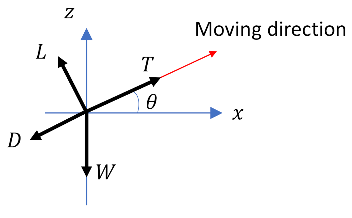
Let W denote the gravity on the UAV, D denote the drag force (parallel to the UAV moving direction; see Figure 4), and L denote the lift force (perpendicular to the UAV moving direction; see Figure 4). These forces have the following relationships:
T D W sin θ = 0 ,
L W cos θ = 0 ,
where D = 1 2 ρ C D A w V 2 , ρ is the air density, A w is the wing area, C D = C D 0 + C L 2 ε π R a is the coefficient of drag, C D 0 is the parasitic drag coefficient, C L = 2 W ρ A w V 2 is the coefficient of lift, R a is the aspect ratio of the wing, and ε is the Oswald efficiency factor [7].
With (6) and the model of the drag D, we have
P m = 1 η m ( 1 2 ρ A w C D 0 V 3 + 2 W 2 cos 2 θ ε π ρ A w R a V + W V sin θ ) .
We can see that the flight path angle θ plays a key role in (8). The power when the UAV ascends (i.e., θ > 0 ) is larger than that when the UAV descends (i.e, θ < 0 ).
Let E denote be the residual energy of the battery, for which the upper bound is E m a x . The residual energy of the battery is defined as the difference between the energy harvesting power and the consumption power, i.e.,
E ˙ = P s P m P 0 ,
where P 0 is the static power consumed to maintain operation of the UAV. Besides (9), some other models can also be used to characterize the residual energy of the battery; see, e.g., [13].

3.5. Problem Formulation

We are interested in planning an inspection tour for the solar-powered UAV so that the UAV starts from an initial position (such as the UAV depot, which can be one of the sites), visits each site once, and returns to the initial position while maintaining positive residual energy and avoiding collision with mountains. The objective function can be set as the minimization of the time to return to the initial position.
Let t 0 denote the given starting time, p 0 X f be the initial position, θ 0 be the initial flight path angle, ψ 0 be the initial heading angle, E 0 be the initial energy in the battery, t f denote the final time when the UAV returns to p 0 , and σ be the inspection tour. Then, our problem can be formulated as follows:
min σ t f
subject to
σ ( t 0 ) = p 0 , θ ( t 0 ) = θ 0 , ψ ( t 0 ) = ψ 0 , E ( t 0 ) = E 0 ,
σ ( t f ) = p 0 ,
σ ( t ) N i , t [ t 0 , t f ] , i ,
min q S σ ( t ) q d s , t [ t 0 , t f ] ,
E ( t ) > 0 , t [ t 0 , t f ] .
In the above problem formulation, constraints (10a) and (10b) set the initial and final conditions. Constraint (10c) requires that each site is visited. Constraint (10d) requires the UAV to avoid collision with mountains. Since the initial position is in the free space, the UAV will always be in the free space during flight with constraint (10d). Constraint (10e) requires that the residual energy is maintained positive.
With the presented models, some other problems can also be formulated. For example, if we look for the minimum initial energy to complete the inspection mission within a certain time, we can replace the objective function using min σ E ( t 0 ) , removing the initial energy condition in (10a), and adding an extra constraint: t f t 0 is no larger than a given constant. Moreover, when we consider safe landing at the end or in any emergency situation, the constraint (10e) can be replaced by E ( t ) being not smaller than a given constant, which should be sufficient for landing.

4. Proposed Solution

As aforementioned, the considered problem (10) is more difficult than the conventional TSP, since it couples low-level trajectory planning and high-level site visiting order scheduling. Moreover, it involves energy management during flight. The residual energy relies on the harvested and consumed amount, which further depend on the UAV trajectory. Instead of completely solving the problem of interest, in this section, we present our method to address the case where we have a visiting order of the sites. This order can be obtained by solving a TSP instance, where the distance between two sites is approximated by the Euclidean distance. With the visiting order, our tour planning method consists of two steps. Firstly, we construct a feasible tour that passes the sites following the visiting order, stays away from the mountains, and satisfies that the residual energy remains positive at any time. Secondly, we improve the tour to shorten the completing time while satisfying the residual energy constraint, staying away from the mountains and not missing any site.

4.1. Feasible Inspection Tour

The proposed feasible inspection tour planning method is based on RRT. Generally, RRT is used to plan a feasible point-to-point path. The reason for using RRT is that it constructs a tree incrementally from a root (1) by randomly generating samples and (2) by finding the nearest vertices in the tree and applying appropriate control inputs to generate new vertices. In the tree structure, each vertex, other than the root, has a unique parent vertex. A path in the tree consists of a sequence of vertices. As a randomized method, in general, RRT can find a path quickly in complex environments. Since any vertex on the path is generated by appropriate control inputs, the constructed path is feasible to the UAV without any further smoothing operation.
For the convenience of presenting the method, we introduce some new symbols.
  • V : the set of vertices of the random tree. Each vertex τ V is annotated with { x , u , e , or t } , which are the state, the control input, the residual energy, and the time instant, respectively (e and t are defined below).
  • E : the set of edges of the random tree.
  • δ : a time interval, used in generating new vertices. Any vertex in the random tree can be reached from its parent vertex in the time interval δ .
  • t: the time instant annotated with a vertex. t increases incrementally from the initial time t 0 by δ , such as t 0 + δ , t 0 + 2 δ , etc.
  • e: the residual energy annotated with a vertex, upper bounded by E m a x .
  • U: the set of control inputs. Let n μ and n ϕ be two given positive integers. They specify the number of feasible control inputs, respectively, and are dependent on the maneuverability of the UAV. Then, u U = { ( μ , ϕ ) | j μ U m a x n μ , j μ = n μ , n μ + 1 , , n μ , j ϕ Φ m a x n ϕ , j ϕ = n ϕ , n ϕ + 1 , , n ϕ } [24].
  • f ( τ ) : gives the specified annotation of the vertex τ . For example, p ( τ ) gives the position of τ and e ( τ ) gives the residual energy of τ .
The roles of the employed functions are explained below.
  • τ 1 = N e a r e s t ( τ , V ) : returns the nearest vertex τ 1 V to τ in terms of a given distance function such as the Euclidean distance.
  • u = S u i t a b l e I n p u t ( τ 1 , τ 2 ) : finds the appropriate control input u U so that, when the UAV starts from the vertex τ 1 and applies u, it will move towards τ 2 for the interval δ in the mostly energy-efficient way.
  • τ 2 = S t e e r ( τ 1 , u ) : generates a new vertex τ 2 from the parent vertex τ 1 by applying the control input u. In this function, the time instant of τ 2 is incremented from that of τ 1 by δ ; the state of τ 2 is computed by the UAV model (1) with the input u; and the residual energy is computed by (9).
  • G a i n ( τ 1 , τ 2 ) : returns the net energy saving when the UAV moves from vertex τ 1 to τ 2 . Consider that the residual energy of the UAV at vertex τ 1 is e ( τ 1 ) and the UAV can further reach τ 2 from τ 1 . Then, the residual energy at τ 2 is given by e ( τ 2 ) = min { e ( τ 1 ) + G a i n ( τ 1 , τ 2 ) , E m a x } . This function can also take several vertices, i.e., a path, as input. This will be used in Section 4.3.
  • C o l l i s i o n F r e e ( τ 1 , τ 2 ) : returns true if the trajectory from τ 1 to τ 2 avoids collisions with mountains.
Let s 0 = s n + 1 = p 0 be the virtual starting and ending sites. Then, the visiting sequence of the UAV becomes { s 0 , s 1 , , s n , s n + 1 } . For every two consecutive sites in this visiting sequence, we can construct a random tree by setting the former site as the starting position and the latter as the goal position. The random tree can be constructed following the framework of the conventional RRT.
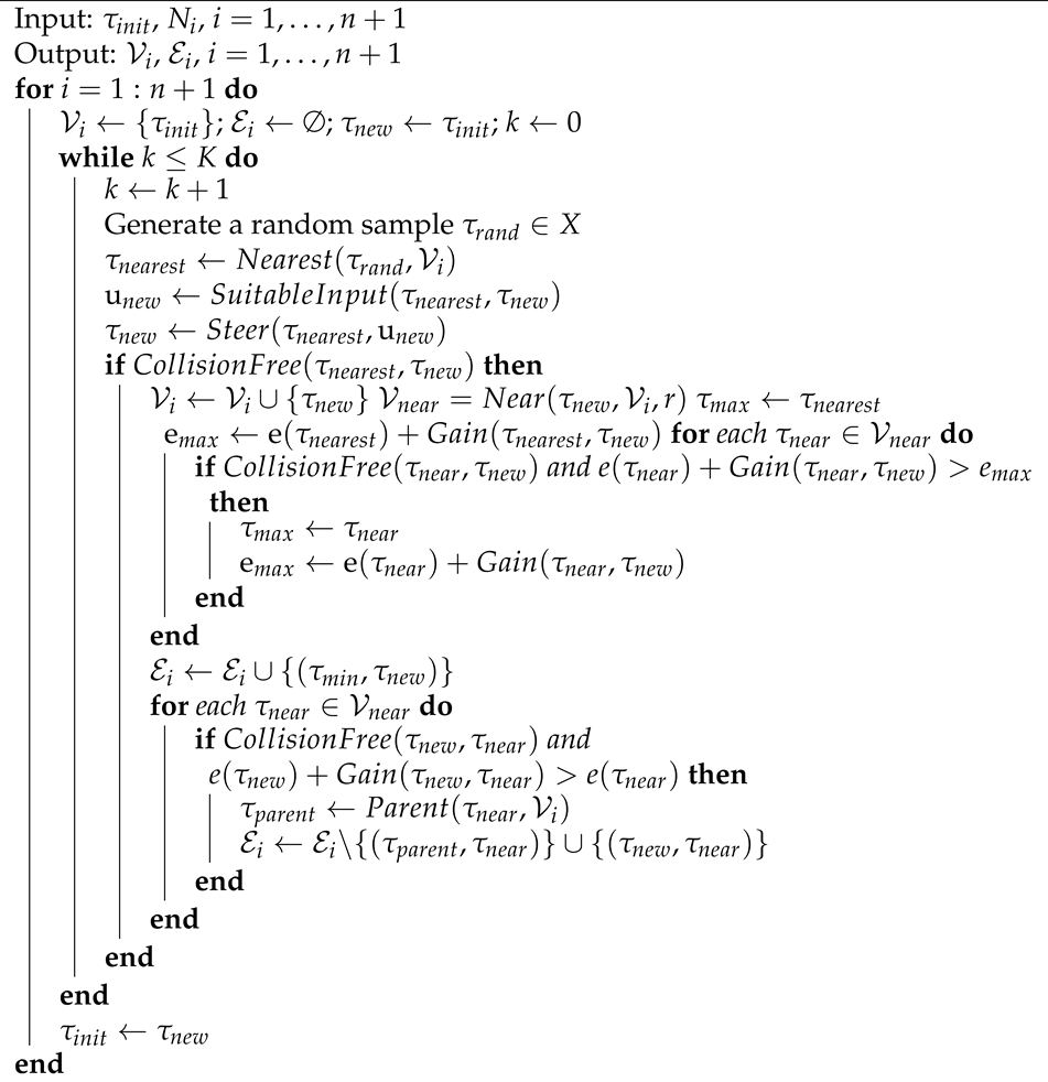
With the above symbols and functions, a set of random trees are constructed by Algorithm 1. N n + 1 is the neighbourhood of s n + 1 , K is the maximum number of generated samples, and τ i n i t = { ( p 0 , θ 0 , ψ 0 ) , , E 0 , t 0 } . In the first while-loop, the algorithm constructs the random tree by taking p 0 as the initial position and N 1 as the destination set. A while-loop terminates after K random samples have been generated. K should be sufficient so that a path exists from the initial position to the destination set. Then, the algorithm constructs the next random tree, where the vertex inside the neighbourhood of the last site becomes the initial vertex, i.e., τ i n i t . Algorithm 1 returns n + 1 trees, where the root of a latter tree is a vertex of the former tree. In other words, the trees are connected by these vertices. If the residual energy at the vertex that enters the neighbourhood N n + 1 is positive, then a feasible tour exists. That vertex is the ending vertex of the tour. We can find this tour by tracking the parent of the last vertex in the tour until the initial vertex is tracked. An illustration is shown in Figure 5.
Algorithm 1: Random trees.
Energies 14 01968 i001
In Algorithm 1, a set of n + 1 random trees are constructed in sequence. One may ask why we do not construct these trees in parallel following the spirit of rapidly exploring dense trees (RDTs) [25]. In RDTs, the cost from one vertex τ 1 to another vertex τ 2 is the same as that from τ 2 to τ 1 . Then, the constructed trees rooting at the starting position and the destination can be merged. However, this does not apply to the considered problem. In our problem, the energy gained when the UAV moves from τ 1 to τ 2 may not be the same as the reverse. A simple example is that the UAV increases its altitude from τ 1 to τ 2 . In this movement, energy is spent for such an increase in the altitude. However, if the UAV moves from τ 2 to τ 1 , the altitude decreases, and it gains energy from the altitude decrease. Another reason is that the energy harvesting power is time-varying, which depends on the sunlight direction. Constructing the trees in parallel cannot characterize well the energy harvesting power as the time to reach the vertices cannot be accurately set. The presented Algorithm 1 can solve these issues. Specifically, the edges of the random trees are directed and each vertex in a tree is annotated with a time, both of which facilitate residual energy computation.

4.2. Energy-Efficient Feasible Inspection Tour

Algorithm 1 constructs a set of connected random trees and then finds the feasible tour satisfying the energy requirement. Although each vertex is generated in a mostly energy-efficient way (see the function S u i t a b l e I n p u t ( ) ), the tour is not optimal in terms of energy, and this is a common shortcoming of RRT-based planning methods.
In this section, we follow the idea of RRT* [26], especially the idea of rewiring, to improve the energy efficiency of the vertices in the random trees. This is necessary when Algorithm 1 fails to find a feasible tour. The body of Algorithm 2 is similar to that of Algorithm 1. The used functions are explained below.
  • τ 1 = P a r e n t ( τ , V ) : returns the parent vertex τ 1 V of τ . By convention, the parent vertex of the root is itself.
  • V n e a r = N e a r ( τ , V , r ) : returns the subset of vertices V n e a r V that are within the ball centred at τ of radius r > 0 . The radius r is used to determine the number of the selected neighbour vertices. As opposed to a fixed value, r scales with the cardinality of V to maintain a small number of rewiring candidates [26].
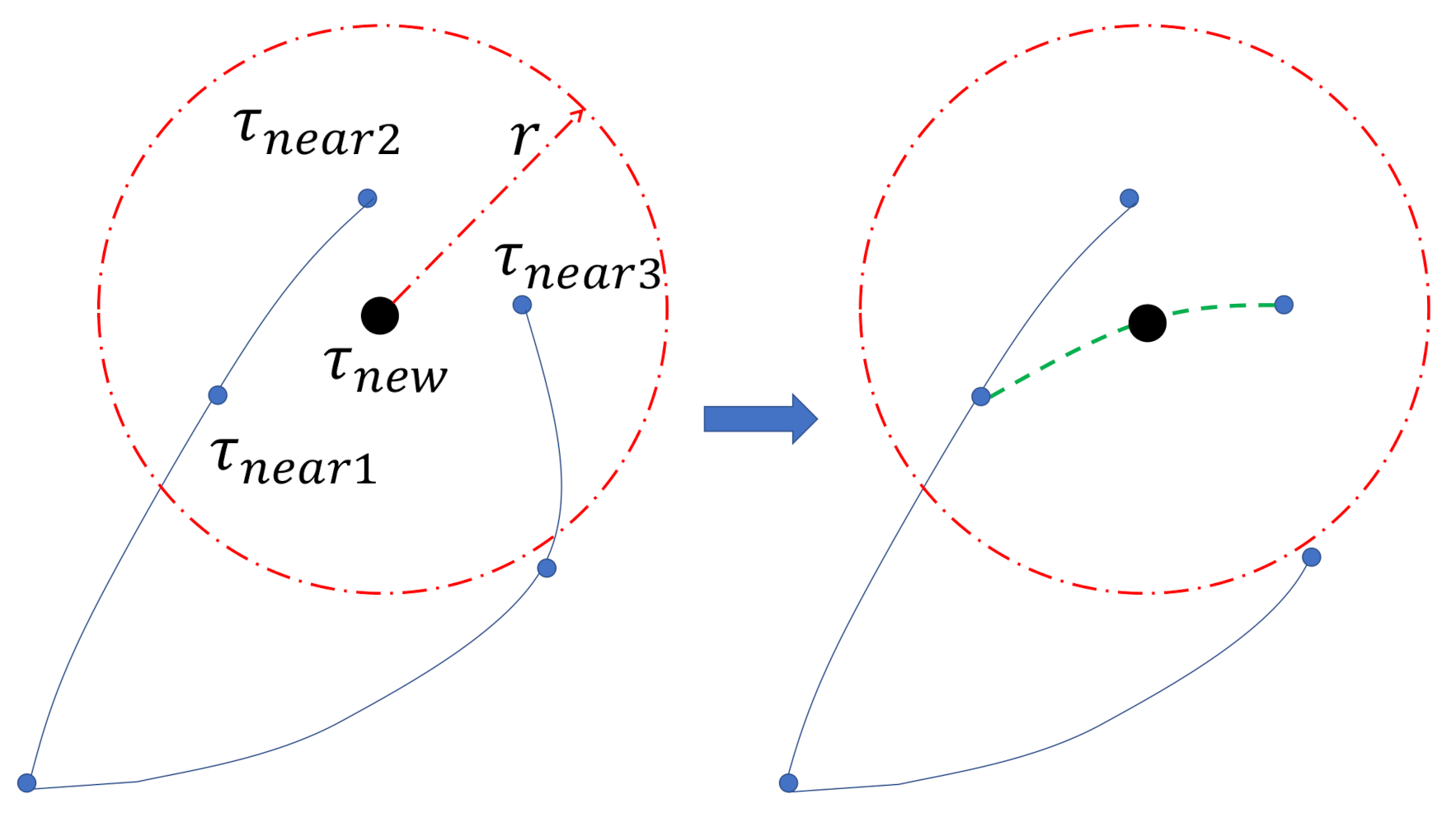
Compared to Algorithm 1, the additional operations of Algorithm 2 include the two for-loops in lines 14–18 and lines 19–22, respectively. The first one (lines 14–18) is to find the vertex in the neighbourhood V n e a r that leads to the maximum residual energy at the new vertex τ n e w . Such a vertex, denoted by τ m a x in line 16, may not necessarily be τ n e a r e s t , since τ n e a r e s t is found according to a distance metric rather than the residual energy. Once this vertex is found, an edge between this vertex and τ n e w is added to the edge set (see line 18). The second operation (lines 19–22) is the rewire for the vertices in V n e a r . Specifically, if a vertex τ n e a r V n e a r that can be reached via τ n e w has more residual energy, we remove the edge from the parent of τ n e a r to τ n e a r from the edge set and add the edge from τ n e w to τ n e a r to the edge set (see line 22). An illustrative example is shown in Figure 6.
It is easy to understand that the inspection path obtained from the random trees generated by Algorithm 2 achieves no smaller residual energy than that obtained by Algorithm 1 for the same set of random samples.
Algorithm 2: Energy-efficient random trees.
Energies 14 01968 i002

4.3. Optimized Inspection Tour

When the inspection tour obtained by Algorithm 1 or 2 has positive residual energy at the end, there is room to shorten the completing time of the tour. The main reason is that, in Algorithms 1 and 2, the vertices are linked to achieve larger residual energies. For example, to increase the energy harvesting power, some long edges that are outside shadow regions may be added to the tree; see Figure 7. Then, substituting this type of edge on the tour with some shorter but less energy-efficient ones but less harvested energy can decrease the completing time while satisfying the positive residual energy constraint. In this section, we target improving the feasible tour to shorten the completing time, which is the objective of our problem (10), by sacrificing the energy efficiency.
The feasible tour σ consists of a sequence of vertices, and these vertices belong to n + 1 random trees. Then, we can break the whole tour into n + 1 sub-tours. Let σ i denote the ith sub-tour, where i = 1 , , n + 1 . We have σ = { σ 1 , , σ n + 1 } . The sub-tour σ i consists of a subset of vertices in V i . The objective of shortening the inspection tour is to shorten each sub-tour.
In the ith random tree, there is one vertex located inside the neighbourhood of s i 1 , which is the root of the ith tree. If i = 1 , this vertex is located at p 0 . Additionally, there is one vertex falling into the neighbourhood of s i , as once such vertex is added to the ith tree, and we move onto the construction of the next random tree. Some new symbols and functions used in the improvement method are explained below.
  • σ f i x e d : the sub-tour that has been improved.
  • F i r s t V e r t e x ( σ ) : returns the first vertex of the tour σ .
  • L a s t V e r t e x ( σ ) : returns the last vertex of σ .
  • F i n a l T i m e ( σ ) : returns the completing time of σ .
  • N u m b e r O f V e r t e x ( σ ) : returns the number of vertices in σ .
  • R e a c h a b l e ( τ 1 , τ 2 ) : returns true if these exists a suitable control input u so that the vertex τ 1 can reach τ 2 with u. It is easy to understand that, under the constraints of the control inputs, the UAV may not reach some states from the current one.
  • U p d a t e ( σ ) : update the annotations of the vertices of σ .
  • T i m e U s e d ( τ 1 , τ 2 ) : returns the time the UAV needs from the vertex τ 1 to the vertex τ 2 . This function can also take several vertices, i.e., a path, as the input.
  • σ = P a t h ( τ 1 , τ 2 , V i ) : returns the path from root vertex τ 1 to another vertex τ 2 in the ith random tree, i.e., σ = { τ 1 , , τ 2 } . Every vertex in a tree is reachable from the root, and this function returns a unique path between the vertices τ 1 and τ 2 .
  • P o s i t i v e E n e r g y ( σ ) : returns true if all the vertices of the tour σ have positive residual energy, i.e., e ( τ ) > 0 , τ σ .
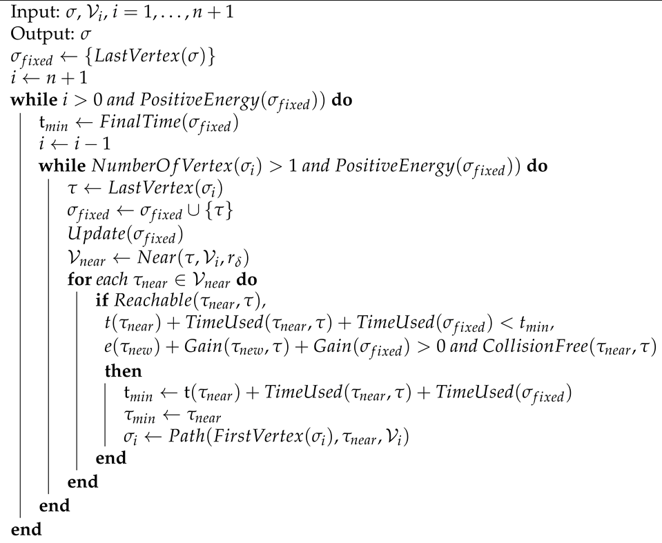
Our improvement method shortens the feasible tour in a backward way, as shown in Algorithm 3. The inputs of this algorithm are the feasible tour σ and the set of the random trees. The improved sub-tour is stored in σ f i x e d , which is initialized by the final vertex of σ . We look at each sub-tour σ i from the last one σ n + 1 until the first one σ 1 . Every time, we examine the last vertex in the sub-tour σ i and add it the final tour σ f i x e d (see line 7–8). Then, the vertices of the tour σ f i x e d are updated. Specifically, as the first vertex of σ f i x e d , i.e., the newly added one, may be reached in an earlier time, the annotations of other vertices of σ f i x e d need to be updated, and such an update is executed in line 9. We look at the neighbourhood of this vertex (see line 10) and find the vertex in its neighbourhood that can shorten the completion time while satisfying the residual energy constraint. Note that this neighbourhood is defined by a radius r δ and that such a neighbourhood is reachable from the vertex in one time interval δ . Among those that satisfy the conditions listed in line 12, the vertex that leads to the quickest completion time is assigned as τ m i n (see line 14). Then, the left sub-tour is updated by the one from the root of this random tree to the vertex τ m i n (see line 15). An illustrative example is shown in Figure 8. The vertex τ is currently under evaluation. There are two vertices in its neighbourhood. Suppose that the previous sub-tour is from τ 1 to τ via τ n e a r 1 . If following the path from τ 1 to τ via τ n e a r 2 leads to less time and satisfies the residual energy constraint, the current sub-tour is updated by P a t h ( τ 1 , τ n e a r 2 , V i ) . The next vertex to be examined becomes τ n e a r 2 . This operation terminates when only one vertex, i.e., the root, left in the current sub-tour or the residual energy of any vertex of σ f i x e d cannot be positive any more (see line 5). The improvement process repeats for each sub-tour, from σ n + 1 back to σ 1 . It may also terminate if the residual energy of a vertex of σ f i x e d becomes negative (see line 3).
It is worth pointing out that Algorithm 3 is one way to shorten the inspection tour. Other options include shortening the tour in a forward way and shortening the most time-consuming sub-tour first. Although Algorithm 3 is not guaranteed to deliver the optimal inspection tour, it can shorten the tour while maintaining positive residual energy, not missing any site and avoiding collisions with mountains.
Algorithm 3: Tour improvement.
Energies 14 01968 i003

5. Simulation Results

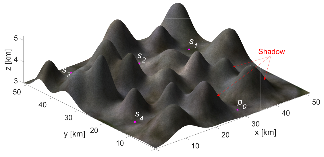
In this section, we present computer simulation results conducted in MATLAB to confirm the performance of the proposed algorithms. The parameters used in our simulations are listed in Table 2 [7,15]. The simulated mountain region is shown in Figure 9, with a UAV depot and four sites (randomly selected). The shadow regions created by the mountains are illustrated in Figure 9. The neighbourhood of a site is set as a cylinder with radius 2 km and height 0.5 km. The iteration number K is first set as 5000. Initially, the UAV heads towards site 1 and the residual energy in the battery is E 0 = 10 Wh. The simulated location is Sydney, where the latitude and longitude are 33.87 S and 115.21 E, and the starting time is 13:00 on the first day of a year. These values are used to compute the azimuth angle α z and the elevation angle α e of the sun. More details can be found in [15,16]. The below results are all in this simulation setting. When we change the number of sites and their locations, similar results can be obtained.
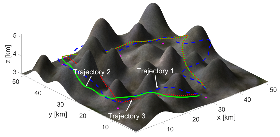
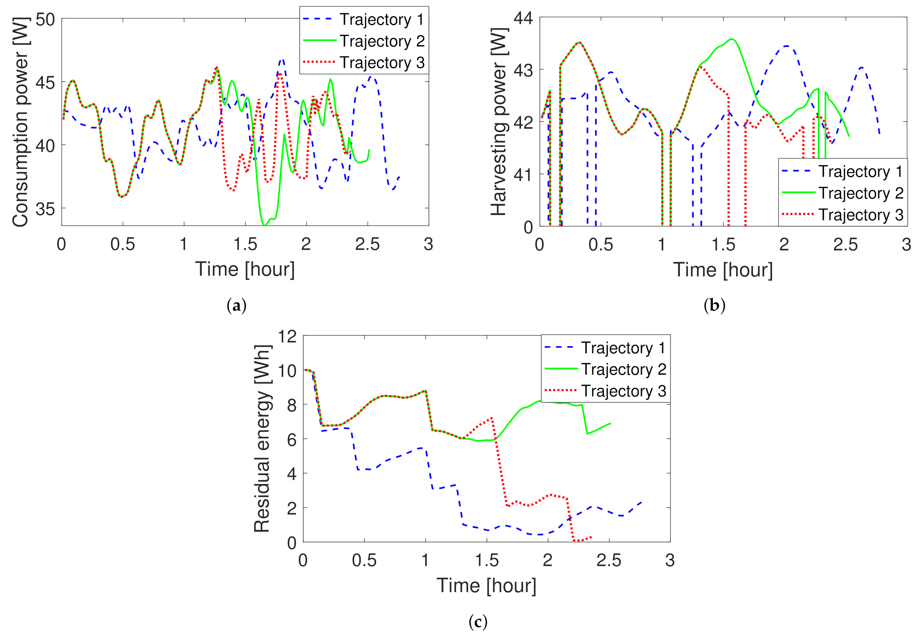
We apply Algorithms 1 and 2 to construct random trees. The obtained trajectories are shown in Figure 10, and the energy consumption power, the energy harvesting power, and the residual energy of these trajectories are shown in Figure 11. We can see that it takes 2.8 h to complete the surveillance mission following Trajectory 1 (which is obtained from the random trees generated by Algorithm 1). Trajectory 2, obtained from the random trees generated by Algorithm 2, achieves much better performance in terms of the residual energy at the end of the mission. Moreover, Trajectory 2 takes less time than Trajectory 1. From Figure 11b, we can see that a smaller part of Trajectory 2 than Trajectory 1 is in the shadow. As seen from Figure 11a, the energy consumption power along Trajectory 1 is generally larger than that along Trajectory 2, and the total consumption energies are 115 and 103.8 Wh, respectively. Trajectory 3, obtained by Algorithm 3, is the same as Trajectory 2 for 1.3 h (see the overlapped part of these two trajectories in Figure 10 and Figure 11). Trajectory 3 takes about 2.39 h to complete the mission, which is 10 min less than that of Trajectory 2. The reason for this is that Trajectory 3 has a larger part inside the shadow regions than Trajectory 2, which harvests less energy but takes less time; see Figure 10 and Figure 11b. As can seen from Figure 11c, the residual energy of the UAV moving along Trajectory 3 is close to zero at the end of the mission. Table 3 summarizes the significant differences between these trajectories.
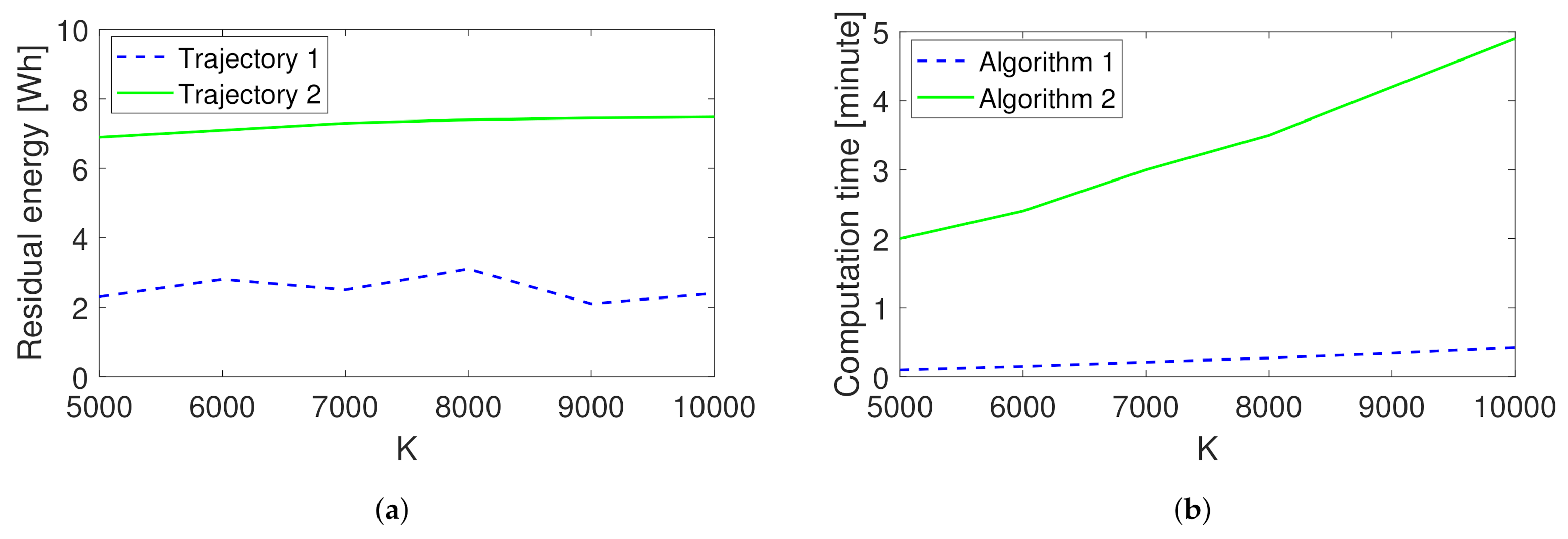
We are also interested in the impacts of several key parameters on our algorithms. K plays an important role in constructing the random trees. To have a look at K’s impact, we keep the set of random samples the same for Algorithms 1 and 2. Moreover, when we increase K, we reuse the existing samples. As seen from Figure 12a, the residual energy of the trajectory obtained by Algorithm 2 increases with K but the increasing rate drops slightly with K. Additionally, the computation time (measured in MATLAB on a computer with Intel(R) Core(TM) i5-6500 CPU @ 3.20 GHz 3.20 GHz and 8 GB RAM) also increases with K; see Figure 12b. The impact of K on the trajectory obtained by Algorithm 1 is different. The reason is as follows. In Algorithm 2, whenever a new vertex is generated, a rewiring operation is executed. Then, the neighbour vertices are reconnected to obtain a lower cost. When K is extremely large, the most energy-efficient trajectory can be obtained, but the cost is the computation time. Differently, Algorithm 1 does not rewire vertices. A better trajectory will be obtained only if the suitable random samples are generated. Moreover, the computational time of Algorithm 3 is independent on K. As it aims to improve a given trajectory, the computational time of Algorithm 3 varies with different given trajectories. For the current considered setting, Algorithm 3 is completed within 10 s.
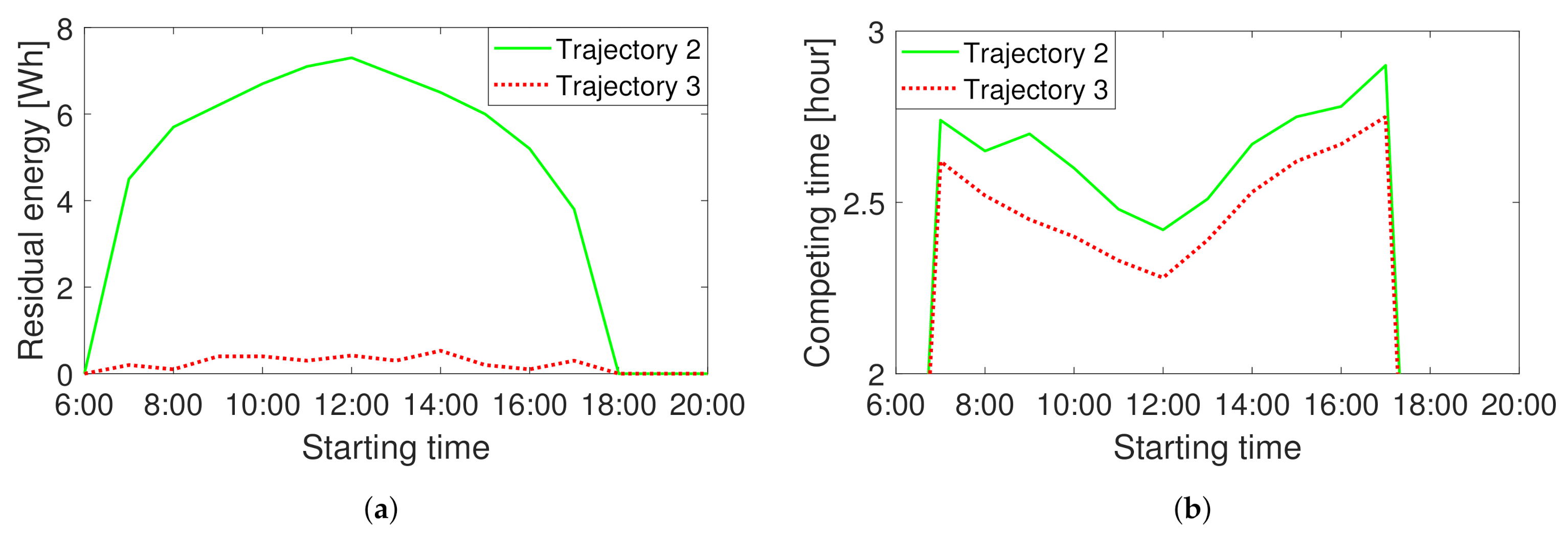
Figure 13 demonstrates the impact of the starting time t 0 . At the considered location and on the considered day, the sunrise was at 5:47 and the sunset was at 20:09. We conducted simulations with starting times from 6:00 to 20:00. We set K as 5000. As shown in Figure 13, starting too early or too late does not result in feasible inspection paths. The reason mainly lies in the harvesting energy. At the time near sunrise and sunset, the harvesting power is very low. During the daytime, with an increase in starting time, the residual energy and the completion time of the trajectory obtained by Algorithm 2 firstly increase and then decrease. For the trajectory obtained by Algorithm 3, the residual energy is near zero no matter when we start, but the completion time first decreases and then increases with the starting time. The shortest completion time is observed when the UAV starts at 12:00. Moreover, Algorithm 3 can shorten the inspection time by about 10 to 15 min in the simulations.

6. Conclusions

In this paper, we considered the path planning problem for a solar-powered UAV inspecting a set of sites for safety and rescue in a mountain area. The proposed path planning method first finds out a feasible inspection path that enables the UAV to complete the mission based on RRT. Moreover, following the idea of RRT*, the energy efficiency of the feasible inspection path can be improved by rewiring the vertices in the random trees. Then, the method targets shortening the path by sacrificing energy efficiency while not violating the residual energy constraint. The effectiveness of the proposed method was confirmed by computer simulations. As a first trail to address this complex problem, the proposed method is based on a given visiting sequence. Developing methods to relax this condition is one of our future research directions. Moreover, taking into account the effects of real-world disturbances, such as wind gusts and the time-varying formation and position of clouds, in the planning is also worth investigating. The current method is designed for a single UAV. To further improve the time locating a target, developing methods for multiple UAVs is another research direction.

Author Contributions

Conceptualization, A.V.S.; methodology, A.V.S.; software, H.H.; validation, H.H.; formal analysis, H.H.; investigation, H.H.; resources, H.H.; writing—original draft preparation, H.H.; writing—review and editing, A.V.S.; visualization, H.H.; supervision, A.V.S.; project administration, H.H.; funding acquisition, A.V.S. Both authors have read and agreed to the published version of the manuscript.

Funding

This work was supported by the Australian Research Council. Additionally, this work received funding from the Australian Government via grant AUSMURIB000001 associated with ONR MURI grant N00014-19-1-2571.

Institutional Review Board Statement

Not applicable.

Informed Consent Statement

Not applicable.

Conflicts of Interest

The authors declare no conflict of interest.

Abbreviations

The following abbreviations are used in this manuscript:
UAVUnmanned aerial vehicles
RRTRapidly exploring random tree
TSPTravelling salesman problem
TSPNTravelling salesman problem with neighbourhood
LoSLine-of-sight

References

  1. Silvagni, M.; Tonoli, A.; Zenerino, E.; Chiaberge, M. Multipurpose UAV for search and rescue operations in mountain avalanche events. Geomat. Nat. Hazards Risk 2017, 8, 18–33. [Google Scholar] [CrossRef] [Green Version]
  2. Nakadai, K.; Kumon, M.; Okuno, H.G.; Hoshiba, K.; Wakabayashi, M.; Washizaki, K.; Ishiki, T.; Gabriel, D.; Bando, Y.; Morito, T.; et al. Development of microphone-array-embedded UAV for search and rescue task. In Proceedings of the 2017 IEEE/RSJ International Conference on Intelligent Robots and Systems (IROS, Vancouver, BC, Canada, 24–28 September 2017; pp. 5985–5990. [Google Scholar]
  3. Hayat, S.; Yanmaz, E.; Brown, T.X.; Bettstetter, C. Multi-objective UAV path planning for search and rescue. In Proceedings of the 2017 IEEE International Conference on Robotics and Automation (ICRA), Singapore, 29 May–3 June 2017; pp. 5569–5574. [Google Scholar]
  4. Huang, H.; Savkin, A.V. Energy-Efficient Autonomous Navigation of Solar-Powered UAVs for Surveillance of Mobile Ground Targets in Urban Environments. Energies 2020, 13, 5563. [Google Scholar] [CrossRef]
  5. Huang, H.; Savkin, A.V.; Ni, W. Energy-Efficient 3D Navigation of a Solar-Powered UAV for Secure Communication in the Presence of Eavesdroppers and No-Fly Zones. Energies 2020, 13, 1445. [Google Scholar] [CrossRef] [Green Version]
  6. Klesh, A.T.; Kabamba, P.T. Solar-powered aircraft: Energy-optimal path planning and perpetual endurance. J. Guid. Control. Dyn. 2009, 32, 1320–1329. [Google Scholar] [CrossRef] [Green Version]
  7. Lee, J.; Yu, K. Optimal Path Planning of Solar-Powered UAV Using Gravitational Potential Energy. IEEE Trans. Aerosp. Electron. Syst. 2017, 53, 1442–1451. [Google Scholar] [CrossRef]
  8. Bouzid, Y.; Bestaoui, Y.; Siguerdidjane, H. Guidance-Control System of a Quadrotor for Optimal Coverage in Cluttered Environment with a Limited Onboard Energy: Complete Software. J. Intell. Robot. Syst. 2019, 95, 707–730. [Google Scholar] [CrossRef]
  9. Hari, S.K.K.; Rathinam, S.; Darbha, S.; Kalyanam, K.; Manyam, S.G.; Casbeer, D. Efficient Computation of Optimal UAV Routes for Persistent Monitoring of Targets. In Proceedings of the 2019 International Conference on Unmanned Aircraft Systems (ICUAS), Atlanta, GA, USA, 11–14 June 2019; pp. 605–614. [Google Scholar] [CrossRef]
  10. Sachs, G.; Lenz, J.; Holzapfel, F. Unlimited Endurance Performance of Solar UAVs with Minimal or Zero Electrical Energy Storage. In Proceedings of the AIAA Guidance, Navigation, and Control Conference, Chicago, IL, USA, 10–13 August 2009; p. 6013. [Google Scholar]
  11. Gao, X.Z.; Hou, Z.X.; Guo, Z.; Chen, X.Q.; Chen, X.Q. Joint optimization of battery mass and flight trajectory for high-altitude solar-powered aircraft. Proc. Inst. Mech. Eng. Part G J. Aerosp. Eng. 2014, 228, 2439–2451. [Google Scholar] [CrossRef]
  12. Dai, R.; Lee, U.; Hosseini, S.; Mesbahi, M. Optimal path planning for solar-powered UAVs based on unit quaternions. In Proceedings of the 2012 IEEE 51st IEEE Conference on Decision and Control (CDC), Maui, HI, USA, 10–13 December 2012; pp. 3104–3109. [Google Scholar]
  13. Hosseini, S.; Dai, R.; Mesbahi, M. Optimal path planning and power allocation for a long endurance solar-powered UAV. In Proceedings of the 2013 American Control Conference, Washington, DC, USA, 17–19 June 2013; pp. 2588–2593. [Google Scholar]
  14. Spangelo, S.; Gilbert, E.; Klesh, A.; Kabamba, P.; Girard, A. Periodic energy-optimal path planning for solar-powered aircraft. In Proceedings of the AIAA Guidance, Navigation, and Control Conference, Chicago, IL, USA, 10–13 August 2009; p. 6016. [Google Scholar]
  15. Wei, X.; Yao, P.; Xie, Z. Comprehensive Optimization of Energy Storage and Standoff Tracking for Solar-Powered UAV. IEEE Syst. J. 2020, 1–11. [Google Scholar] [CrossRef]
  16. Wu, J.; Wang, H.; Li, N.; Yao, P.; Huang, Y.; Su, Z.; Yu, Y. Distributed trajectory optimization for multiple solar-powered UAVs target tracking in urban environment by Adaptive Grasshopper Optimization Algorithm. Aerosp. Sci. Technol. 2017, 70, 497–510. [Google Scholar] [CrossRef]
  17. Padilla, G.E.G.; Kim, K.J.; Park, S.H.; Yu, K.H. Flight Path Planning of Solar-Powered UAV for Sustainable Communication Relay. IEEE Robot. Autom. Lett. 2020, 5, 6772–6779. [Google Scholar] [CrossRef]
  18. Fu, Q.; Liang, X.; Zhang, J.; Qi, D.; Zhang, X. A Geofence Algorithm for Autonomous Flight Unmanned Aircraft System. In Proceedings of the 2019 International Conference on Communications, Information System and Computer Engineering (CISCE), Haikou, China, 5–7 July 2019; pp. 65–69. [Google Scholar] [CrossRef]
  19. Hosseinzadeh, M. UAV geofencing: Navigation of UVAs in constrained environments. In Unmanned Aerial Systems; Elsevier: Amsterdam, The Netherlands, 2021; pp. 567–594. [Google Scholar]
  20. Booth, K.E.C.; Piacentini, C.; Bernardini, S.; Beck, J.C. Target Search on Road Networks With Range-Constrained UAVs and Ground-Based Mobile Recharging Vehicles. IEEE Robot. Autom. Lett. 2020, 5, 6702–6709. [Google Scholar] [CrossRef]
  21. Huang, H.; Savkin, A.V.; Huang, C. A new parcel delivery system with drones and a public train. J. Intell. Robot. Syst. 2020, 100, 1341–1354. [Google Scholar] [CrossRef]
  22. Matveev, A.S.; Savkin, A.V.; Hoy, M.; Wang, C. Safe Robot Navigation among Moving and Steady Obstacles; Elsevier: London, UK, 2015. [Google Scholar]
  23. Sun, Y.; Xu, D.; Ng, D.W.K.; Dai, L.; Schober, R. Optimal 3D-trajectory design and resource allocation for solar-powered UAV communication systems. IEEE Trans. Commun. 2019, 67, 4281–4298. [Google Scholar] [CrossRef] [Green Version]
  24. Savkin, A.V.; Huang, H.; Ni, W. Securing UAV Communication in the Presence of Stationary or Mobile Eavesdroppers via Online 3D Trajectory Planning. IEEE Wirel. Commun. Lett. 2020, 9, 1211–1215. [Google Scholar] [CrossRef]
  25. LaValle, S.M. Planning Algorithms; Cambridge University Press: Cambridge, UK, 2006. [Google Scholar]
  26. Karaman, S.; Frazzoli, E. Sampling-based algorithms for optimal motion planning. Int. J. Robot. Res. 2011, 30, 846–894. [Google Scholar] [CrossRef]
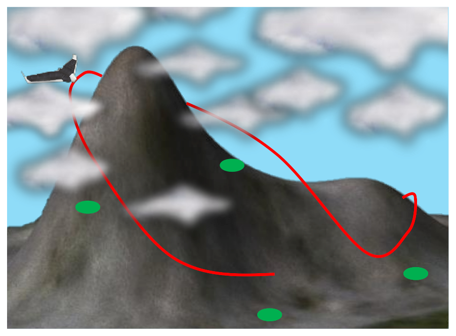
Figure 1. Inspecting mountain sites by a solar-powered unmanned aerial vehicle (UAV).
Energies 14 01968 g001
Figure 2. Illustration of the flight path angle θ , the heading angle ψ , and the bank angle ϕ .
Energies 14 01968 g002
Figure 3. Illustration of the azimuth angle α z , the elevation angle α e , the incidence angle λ , and vectors V s and V s b .
Energies 14 01968 g003
Figure 4. The forces acting on the UAV.
Energies 14 01968 g004
Figure 5. A illustrative feasible inspection tour. The random trees are in different colors, and the red dash curve is a feasible tour. The feasible tour is obtained by repeatedly backtracking the parent of the vertex from the one falling into the neighbourhood of p 0 in the last random tree.
Energies 14 01968 g005
Figure 6. Illustration of rewiring. On the left, three vertices are in the neighbourhood of τ n e w . τ n e a r 3 is rewired to τ n e w as the residual energy via the corresponding path is larger, and the odd edge is removed. The new tree is shown on the right.
Energies 14 01968 g006
Figure 7. The red path, which is outside the shadow region, can harvest more energy but takes a longer time than the blue path, which crosses the shadow region.
Energies 14 01968 g007
Figure 8. An illustration of shortening the ith sub-tour. Suppose in the feasible tour that the vertex τ connects to τ 1 via τ n e a r 1 . τ n e a r 1 and τ n e a r 2 are inside the r δ neighbourhood of τ . If replacing the path from τ 1 to τ via τ n e a r 1 using the path via τ n e a r 2 results in a shorter completion time of the whole tour and the residual energy constraint is satisfied, we update the tour using the latter path via τ n e a r 2 .
Energies 14 01968 g008
Figure 9. The simulated mountain region with a UAV depot and four sites.
Energies 14 01968 g009
Figure 10. The UAV trajectories by Algorithms 1, 2, and 3.
Energies 14 01968 g010
Figure 11. Results about energy. (a) Energy consumption power. (b) Energy harvesting power (When the harvesting power is zero, it means that the UAV is located in the shadow created by the mountains). (c) Residual energy in the battery.
Energies 14 01968 g011
Figure 12. The impact of K on (a) residual energy and (b) computation time.
Energies 14 01968 g012
Figure 13. The impact of t0 on (a) residual energy and (b) path completing time.
Energies 14 01968 g013
Table 1. Frequently used symbols and their meanings.
SymbolMeaningSymbolMeaning
p ( t ) UAV positionVUAV speed
θ ( t ) Flight path angle ψ ( t ) Heading angle
μ ( t ) Flight path angle rate ϕ ( t ) Bank angle
T ( t ) Thrust force D ( t ) Drag force
SMountain surface V s ( t ) Sunlight vector
λ ( t ) Incidence angle E ( t ) UAV residual energy
P s ( t ) Harvesting power P ( t ) Consuming power
s i Site i N i Neighbourhood of site i
l ( t ) LoS indicator σ Inspection tour
Table 2. Parameters used in simulations.
SymbolValueSymbolValue
η m 0.65 η s 0.17
A w 0.787 m 2 A s 0.525 m 2
W25 N P 0 3.9 W
V15 m/s E m a x 20 Wh
C D 0 0.011 R a 3.2
ε 0.8 d s 100 m
δ 2 minG1.367 kW / m 2
Z l o w 3.5 km Z u p 8 km
β c 0.01 ρ 1.29 kg / m 3
U m a x 1 / min Φ m a x 5
n μ 2 n ϕ 2
Table 3. Comparison of the three trajectories.
Trajectory123
Completing time2.80 h2.55 h2.39 h
Residual energy2.3 Wh6.9 Wh0.3 Wh
Energy consumption115.0 Wh103.8 Wh97.4 Wh
Energy harvesting107.3 Wh100.7 Wh87.6 Wh
In-shadow ratio9.0%6.6%12.9%
Publisher’s Note: MDPI stays neutral with regard to jurisdictional claims in published maps and institutional affiliations.