1. Introduction
Gear transmissions are components of propulsion systems commonly used to transform parameters of mechanical energy (torque and speed) between load and drive systems. In other words, gears are applied to fit the values of the rotational speed and mechanical torque of a power source to the required values of their output parameters [
1]. Nowadays, in most commonly applied mechanical gears, the power is transmitted by meshing the gear teeth. The undeniable advantages of mechanical gears are high torque density, efficiency, and ease of manufacture. However, their inherent disadvantages include high noise and vibration levels [
1,
2,
3], friction between teeth [
4], as well as a substantial maintenance cost. The use of magnetic forces for the transmission of mechanical power instead of physical contact removes at least some of the unwanted features of mechanical gears. Magnetic gears (MGs) provide contactless transmission of torque, which allows reducing vibrations and noise as well as increasing the durability [
5,
6,
7,
8], which decreases maintenance cost. Another advantage of the MG is its natural protection against overload [
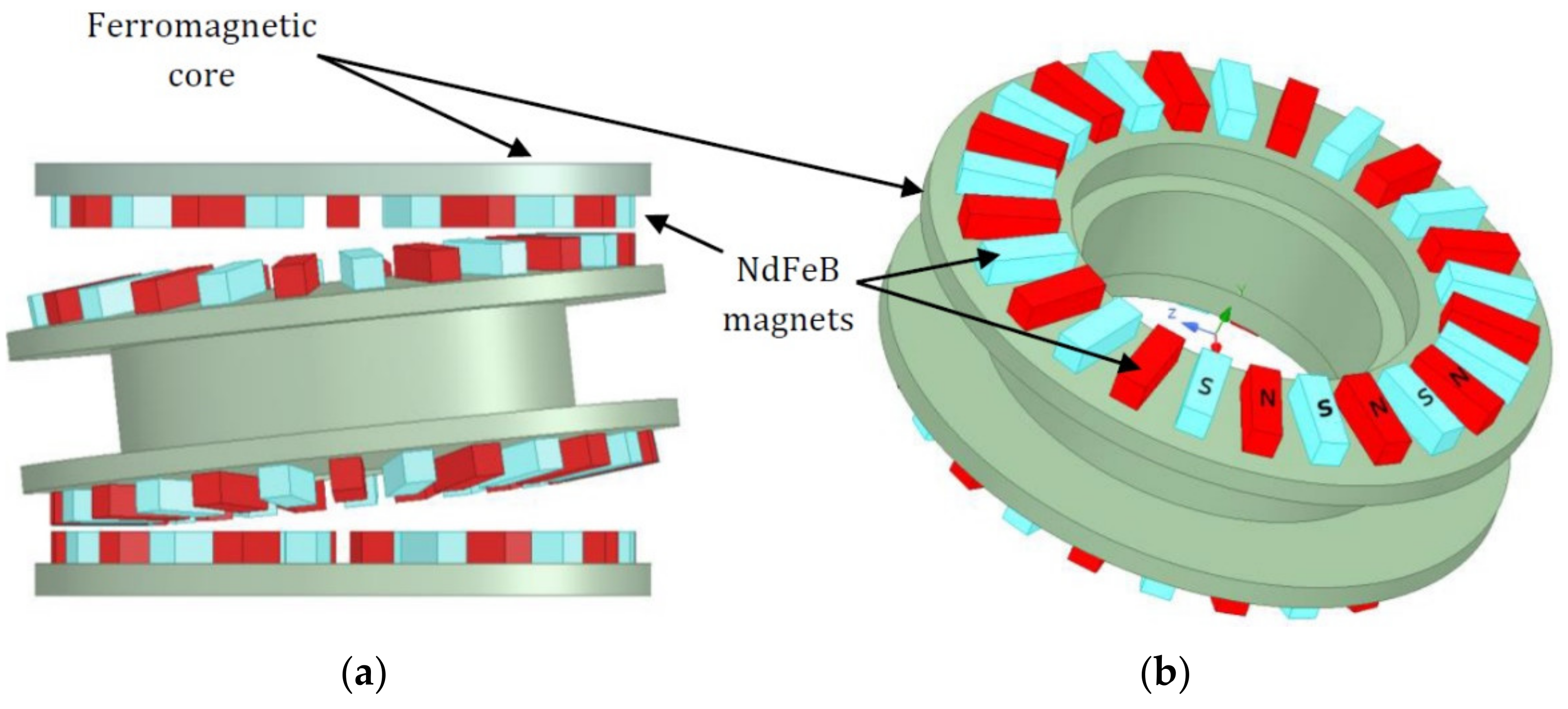
9]. The concept of the MG is not new. The first magnetic gear (shown in
Figure 1a) was patented more than 100 years ago by Armstrong [
10]. The torque transmission was achieved by using the system of electromagnets located on the driving wheel, which were supplied by mechanically commutated currents. The magnetic flux excited by the system of electromagnets was coupled to the driven wheel having non-silent magnetic poles producing reluctance torque. Despite the discussed advantages of reluctance-torque-based designs of MGs, they could not compete with mechanical gears in terms of torque density, due to the limited exploitation of the magnetic circuit and magnetic flux density, which limited the focus on MGs for many years.
Nevertheless, a dynamic growth of interest in MGs can be observed in recent years. The observed rapid development of many different MG designs has become possible, mainly thanks to the invention of neodymium magnets (NdFeB) in the 1980s [
11], as well as the availability of advanced analytical and numerical methods and tools for the analysis and design of complex magnetic circuits such as magnetic equivalent circuits (MECs) [
12], current sheet models (CSMs) [
13,
14,
15], and the finite element method [
16].
Currently, the most common type of magnetic transmissions are the improved topologies of the coaxial magnetic gear (CMG) with ferromagnetic pole-pieces, proposed by Atallah and Howe in 2001 [
17] (
Figure 1b). A change in speed between the inner and outer rotors in a CMG is achieved thanks to the use of ferromagnetic pole pieces (modulators) for modulation of the magnetic field spatial distribution in the working air gaps. The main advantage of CMGs, in contrast to other MG types, is the high torque density (max. 150 Nm/dm
3) resulting from the high exploitation of the magnetic circuit (the torque is transmitted over the whole circumference of the working air gaps). Based on the CMG design, the pseudo direct drive (PDD) was proposed by Magnomatics (shown schematically in
Figure 2). The PDD is an integration of a motor and an MG in one drive unit that consists of an outer stator with electrical windings and an integrated CMG. Such a drive unit offers a much higher torque density in comparison with a conventional drive unit combined with a motor and a gearbox [
18,
19].
According to [
18], the PPD is suitable for many applications ranging from aerospace, automotive, and marine propulsion systems to generators in wind turbines.
Despite its undeniable advantages, CMG and PDD designs allow obtaining only very low transmission ratios (max. 1/10) [
17], which might be a significant limitation in applications requiring high transmission ratios, for example, robots and positioners [
20]. To overcome this limit, a new two-stage magnetic precession gear (MPG) was developed by the authors. It enables obtaining a transmission ratio even higher than 1/1000, which is an unattainable value for any other currently known magnetic gear type. Thanks to this feature and the durability of magnetic gears in general, the MPG may be applied, for example, in precise robots for working in places and environments hard to reach by humans, e.g., in outer space. The detailed 3D finite element method (FEM) analysis of this new type of magnetic gear as well as the experimental investigations of its prototype will be presented in this paper.
The paper is organized as follows. In
Section 2, the design, principle of operation, and brief kinematical analysis are presented. The description of the developed numerical model employing a 3D finite element method is given in
Section 3. Next, the design of the MPG prototype as well as the experimental setup are described in
Section 4. In
Section 5, the results of numerical and experimental tests are presented and discussed. Finally, the conclusions resulting therefrom are formulated in
Section 6.
2. Design of a Two-Stage Magnetic Precession Gear
The idea of an MPG was preceded by mechanical precession gears with face meshing [
20]. Their main advantages were a wide range of possible ratios and a large number of meshing teeth, which allowed transmission of high torque. However, their main drawback turned out to be low maximum efficiency, usually around 20–30% [
21]. To address this problem, the traditional teeth were replaced with neodymium magnets. This eliminated the problem of energy losses associated with the friction occurring in the meshing teeth by the contactless transmission of torque. The magnetic type of precession gear is also considered easier to manufacture as the precise machining of face gears can be challenging [
22].
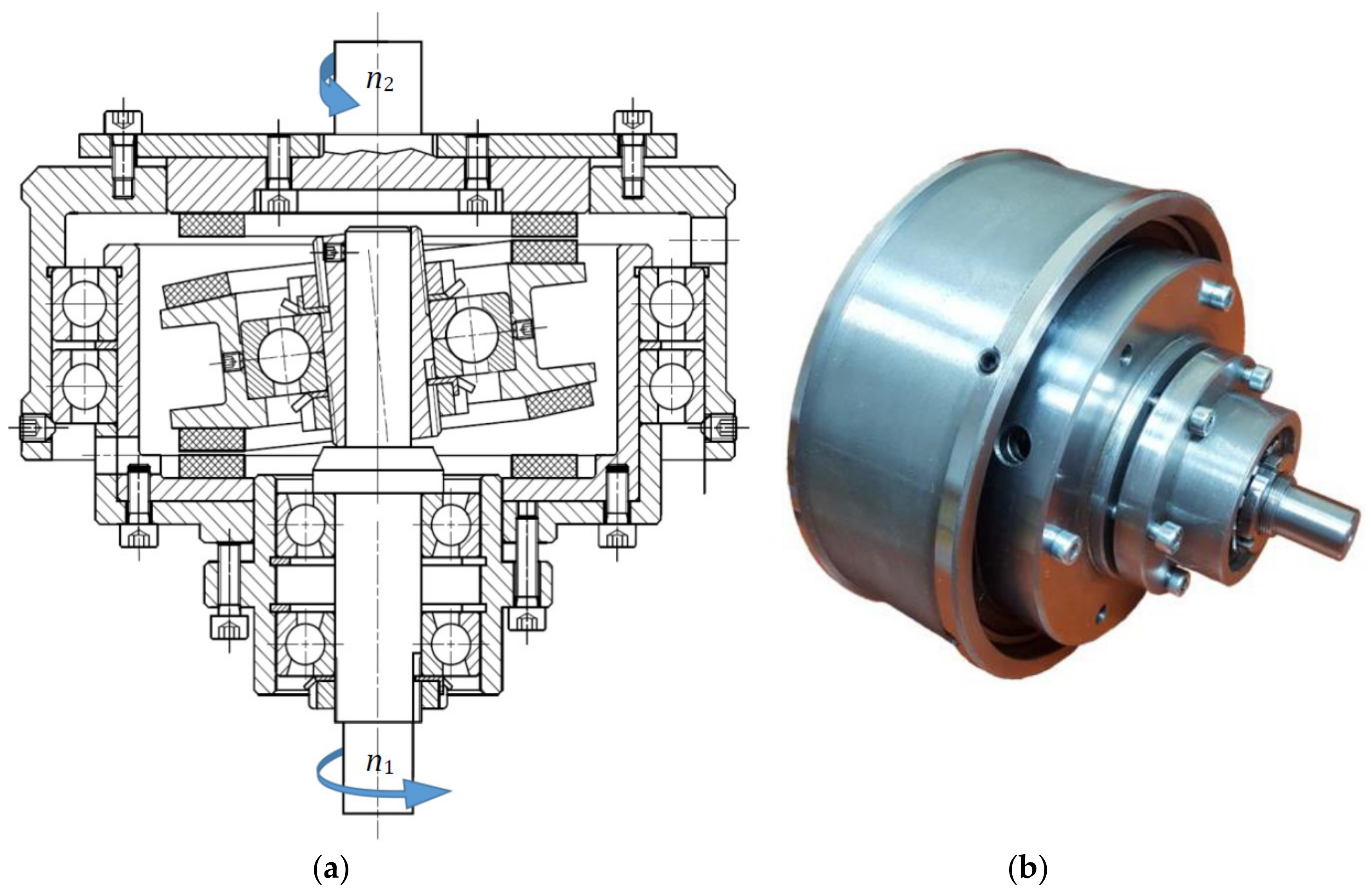
The main components of the proposed two-stage MPG (shown in
Figure 3) are (a) an input shaft, (b) an immovable ring, (c) an intermediate ring, and (d) an output ring with an output shaft. On the circumferences of these rings, permanent magnets are fixed. To achieve a high value of transmitted torque, neodymium, iron and boron magnets of high magnetic energy are applied.
The rotational speed of the output disk (
n2 in
Figure 3) depends on the number of magnets on each disk and is expressed by the formula
where
n1 is the input rotational speed,
n2 is the output rotational speed, and
Ni is the number of neodymium magnets on the
i-th ring.
However, a necessary condition is
The maximal transmission ratio
is achieved when
The input shaft and the output ring rotate about the same main axis of gear rotation (labeled as
Z axis in
Figure 3). The precession movement of the intermediate ring, which is angularly mounted with bearings on the input shaft, has two components. The first one is the rotation about the main
Z axis of gear rotation, forced by the rotational movement of the input shaft. The other is the rotation of the intermediate ring about its own axis (
Zp axis in
Figure 3), inclined relative to the main axis by a precession angle. The rotation about
Zp is caused by the interaction of the magnets placed on the intermediate disk with the magnets on the stationary disk. The magnets fixed to the other side of the intermediate ring interact with the magnets located on the output disk, which causes its rotation.
The movement of the intermediate ring is described by the relation [
23]
where
is the angular velocity of the intermediate ring,
ωin is the angular speed of the input shaft around the
Z axis,
is the unit vector in the
Z direction,
ωp is the angular speed of the intermediate ring around its own axis, and
is the unit vector in the
Zp direction.
The angular speed of the intermediate ring rotation about the
Zp axis is expressed by the formula
The detailed geometrical and kinematical analysis of the presented MPG has been discussed in [
24].
3. Calculation of Torque Transmission
The torque transmitted by the magnetic gears originates from the magnetic forces exerted on the elements of the gear by the interaction of magnetic fields excited by magnetically active materials, i.e., permanent magnets, windings, and ferromagnetic components. To calculate the value of the torque transmitted by the gear, a model allowing one to determine the magnetic fields in the studied transducer must be developed. For determining the distribution of the magnetic fields and calculating the transmitted torque of MGs, an analytical technique based on the current sheet model (CSM) of permanent magnets is often proposed [
13,
14,
15]. The application of the magnetic equivalent circuit (MEC) method [
12] and CSM allows for the determination of the magnetic flux density within the air gaps between movable elements of the MG. The magnetomotive force (MMF) of each permanent magnet is represented by a series of infinitesimal current sheets placed along the magnet height. Despite low computational complexity, the suitability of this method for designing the MG is rather limited. The main reasons for this are the high number of assumptions needed to be made and the complexity of model formulation. The limited usefulness of the analytical methods for designing the MG is especially apparent for MGs with sophisticated geometries and kinematics. Due to the complex structure of the magnetic circuit of the studied MPG, to calculate the transmitted torque in the considered system, a numerical model of the magnetic field was proposed and developed. A detailed discussion about magnetic gear modeling techniques has been given in [
24]. However, in contrast to the previously developed numerical model, the major dimensions of the magnetic circuit (precession angle, magnet sizes, air-gap lengths, as well as the thickness of yokes) were parameterized in order to enable optimized calculations. The application of the FEM to determine the magnetic field distribution allows the precise analysis of the torque transmission process in the studied MPG. Nevertheless, due to the high complexity of the magnetic circuit of the proposed precession gear, a number of simplifications have been imposed in order to find a balance between the computational complexity and the credibility of the results.
First, the geometry of the model was limited to the magnetically active materials such as ferromagnetic discs and permanent magnets. All structural components not interacting directly with the magnetic field, like an enclosure, bearings, shafts, and screws, were neglected. In the development of the mechanical design of the prototype, all auxiliary components potentially electromagnetically active (ferromagnetic, conductive components) were intentionally located at a minimum distance of 20 to 30 mm from the working air gaps in the magnetic field. Moreover, in the studies of torque transmission, the angular positions of the magnetically active elements of the gear were assumed to be known in advance according to the presented kinematical analyses. In other words, the model did not include equations of mechanical equilibrium of the system. Therefore, at the current stage of the research, the impact of the eddy currents induced in the massive conductive elements of the magnetic circuit was neglected. It should be emphasized that the calculation of the eddy currents in the magnetic circuit of such a complex structure is a challenging task in terms of the numerical analysis of systems with an electromagnetic field, and in general, it leads to the necessity of development and application of a model of coupled transient electromagnetic and mechanical phenomena. Such models have extremely high computational complexity, and thus their usefulness at the design stage of MPGs is limited. The general structure of the studied MPG model is shown in
Figure 4a,b. The blue and red colours of the permanent magnet indicate its magnetization directions.
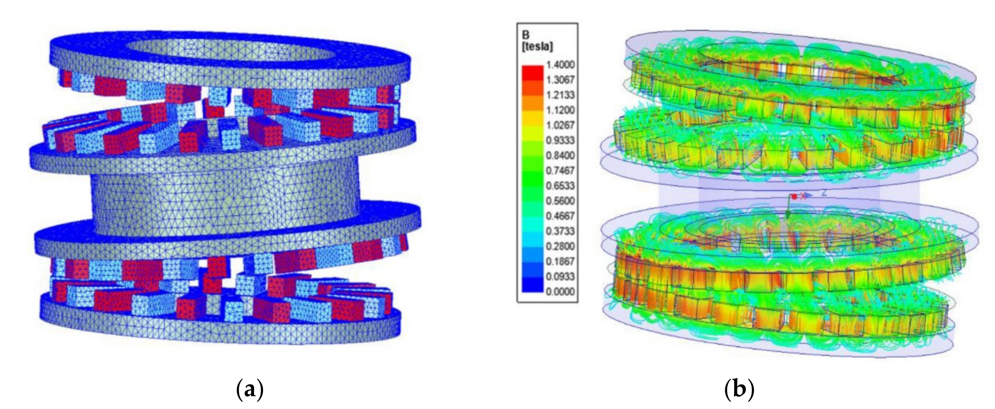
To achieve the precise distribution of the magnetic field allowing for detailed analysis of a torque transmission process, the studied domains were subdivided into more than 830,000 tetrahedral elements. The mesh was refined for magnetically active regions as magnets and air gaps. The visualization of the finite element mesh excluding the air region at the selected position of the gear elements is shown in
Figure 5a, while the corresponding distribution of the magnetic field lines is depicted in
Figure 5b. It can be observed that the studied magnetic circuit is not saturated since the maximum value of the magnetic flux density does not exceed 1.4 T. The increased value of the magnetic flux density can be observed in the regions of the minimum value of the air-gap lengths. It can also be noticed that in these regions, a closed loop of the magnetic flux is formed according to the magnetization direction of the magnets. This flux contributes to the transmission of torque by the gear.
To calculate the transmitted torque between the movable elements of the proposed gear, the Maxwell stress tensor method [
25] was applied. In this approach, the value of the torque acting on each movable component of the gear is calculated as an integral of Maxwell stress tensor components over the integration surface Γ located in the air region that encloses the magnetically active materials of each component highlighted in
Figure 6.
The characteristic feature of magnetic gears, in general, is significantly lower stiffness when compared to mechanical gears. The relation of torque and a mechanical angle between movable elements, due to the similarity of distribution of the magnetic field and occurring physical phenomena, can be understood as an analogue of the dependence of the internal load angle on the load torque value in the synchronous motors [
26,
27].
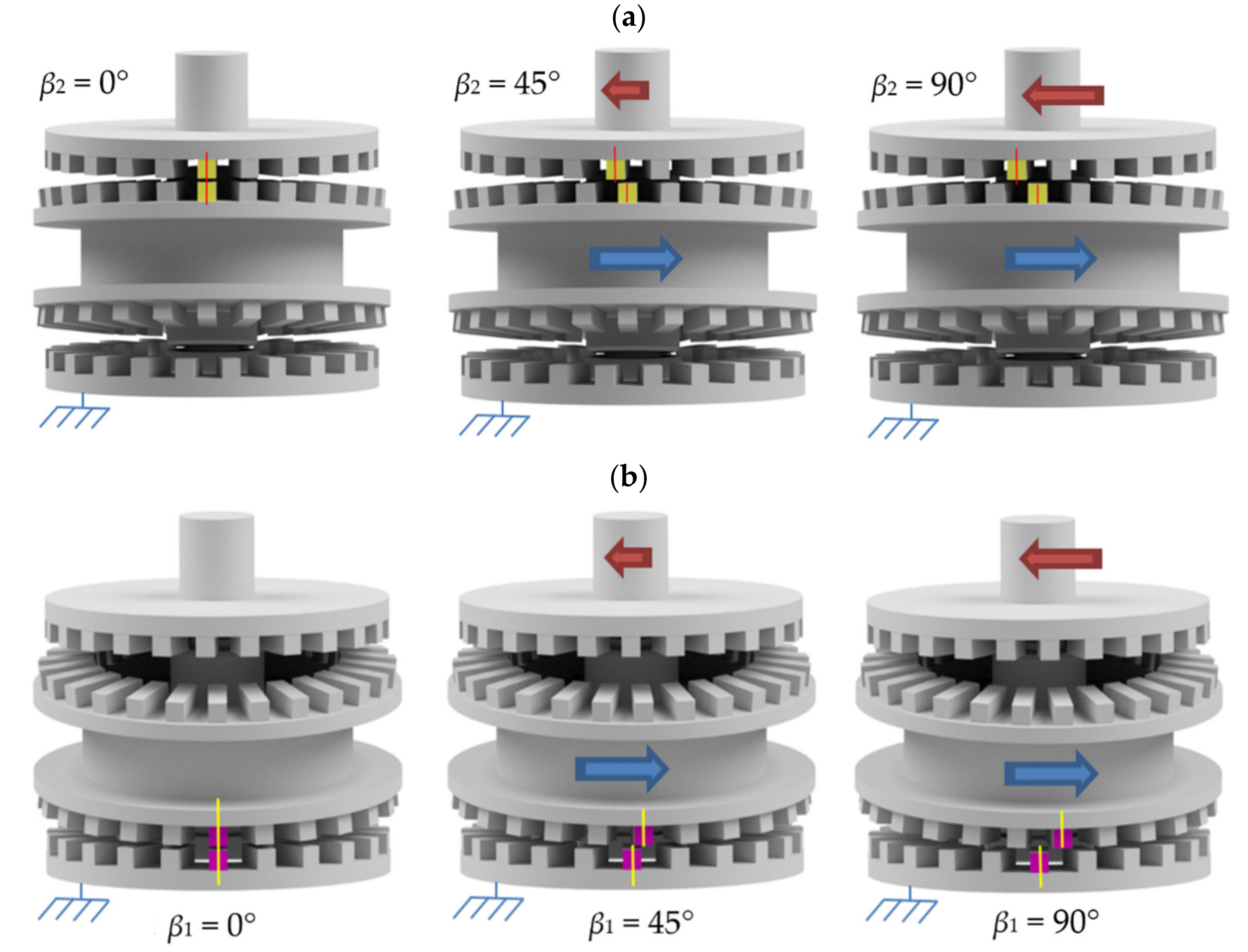
For example, if the mechanical angle
β2m between the intermediate ring and the output ring is expressed by its relation to a number of magnetic pole pairs
p on the output ring (
β2 =
β2m N4/2), the output torque
Tout can be approximated by a sine function of the load angle
β2. By analogy,
Tbase can be expressed as sinusoidal dependence on the load angle
β1 =
β1m N1/2. A more complex situation occurs for torque
Tin, in general, when the input torque is affected by both angles, i.e., it depends on the magnetic field distribution on each side of the intermediate ring. The load angles
β2 and
β1 defined for the studied system are illustrated in
Figure 7a,b, respectively. The blue arrows indicate the direction of rotation, and the red ones indicate the direction of load torque.
In the proposed approach, the dependencies of the torques
Tbase,
Tout, and
Tin on the load angles
β1 and
β2 and air-gap lengths
δ1 and
δ2 (see
Figure 6) are determined on the basis of the developed 3D FEM model of the magnetic field in the proposed MPG. To prove both the correctness and the accuracy of the developed FEM model, the prototype of the gear was designed and built. The design of the MPG prototype as well as the experimental setup are described in the next section of this paper.
4. Prototype and Test Stand
The construction of the two-stage MPG (
Figure 8) was designed to enable adjustment (with the use of gauge blocks and hex keys) of the length of both air-gaps, i.e., between the input ring and the intermediate ring as well as independently between the intermediate ring and the output ring. All the metal parts were made of S235 grade steel. Permanent magnets were glued to rings with the use of special 3D-printed cages. The prototype was built to confirm the principle of MPG operation. Due to the high cost of custom-made magnets, NdFeB magnets in stock were used instead. This affected other geometrical dimensions of the designed MPG, which led to a transmission ratio of 1/144. A precession angle was assumed through initial finite element analysis to achieve the highest output torque. The most important parameters of the prototype of the investigated gear are presented in
Table 1, and its technical drawing, as well as photograph, is shown in
Figure 8.
The research stand (shown in
Figure 9) consists of a servo motor drive produced by BECKHOFF, placed at the input and composed of a servomotor (AM8042) and a servo controller (AX5000); two torque transducers (MT5 and KTR DATAFLEX 22/20) to measure torque at the input and output of the tested gear; as well as a brake (EMA—ELFA P80) to load the gear at the output. Additionally, an encoder (LIKA CK59) was installed at the output to measure the uniformity of the gear operation. The main purpose of this test stand was to determine the gear efficiency as well as the maximum allowable torque for a given rotational speed and given air-gap lengths.
During the tests, no excessive warming of the prototype was registered. The noise level appeared to be lower than in mechanical transmissions with similar ratios; however, thermal and noise-level measurements were not conducted at the current stage of the research. Three repetitions of the same measurements were made under identical conditions.
The results of the conducted experimental investigations and numerical simulations carried out were compared and are discussed in
Section 5.
5. Results and Discussion
This section is organized as follows. First, the results of the experiments are presented and discussed. The conducted tests enable determining the efficiency and examining the influence of rotational speed and air-gap lengths on the maximum load torque. Subsequently, these experimental results are supplemented with simulation results, which show the dependence of the load angle on the length of the air gaps. Finally, a comparison of the characteristics of the load torque as a function of the load angle determined experimentally and by the FEM analysis conducted for selected air-gaps lengths is presented and discussed.
First, the dependence of the maximum load torque carried by the tested gearbox at different values of rotational speed of the input shaft was examined. The obtained characteristic is shown in
Figure 10. A decrease in the maximum load torque transmitted by the examined gear at higher rotational speeds can be observed. Such behavior of the MPG can be explained by the impact of the eddy current losses induced in the steel cores [
28] and the permanent magnets as well as magneto-mechanical resonances occurring in the studied gear [
29,
30].
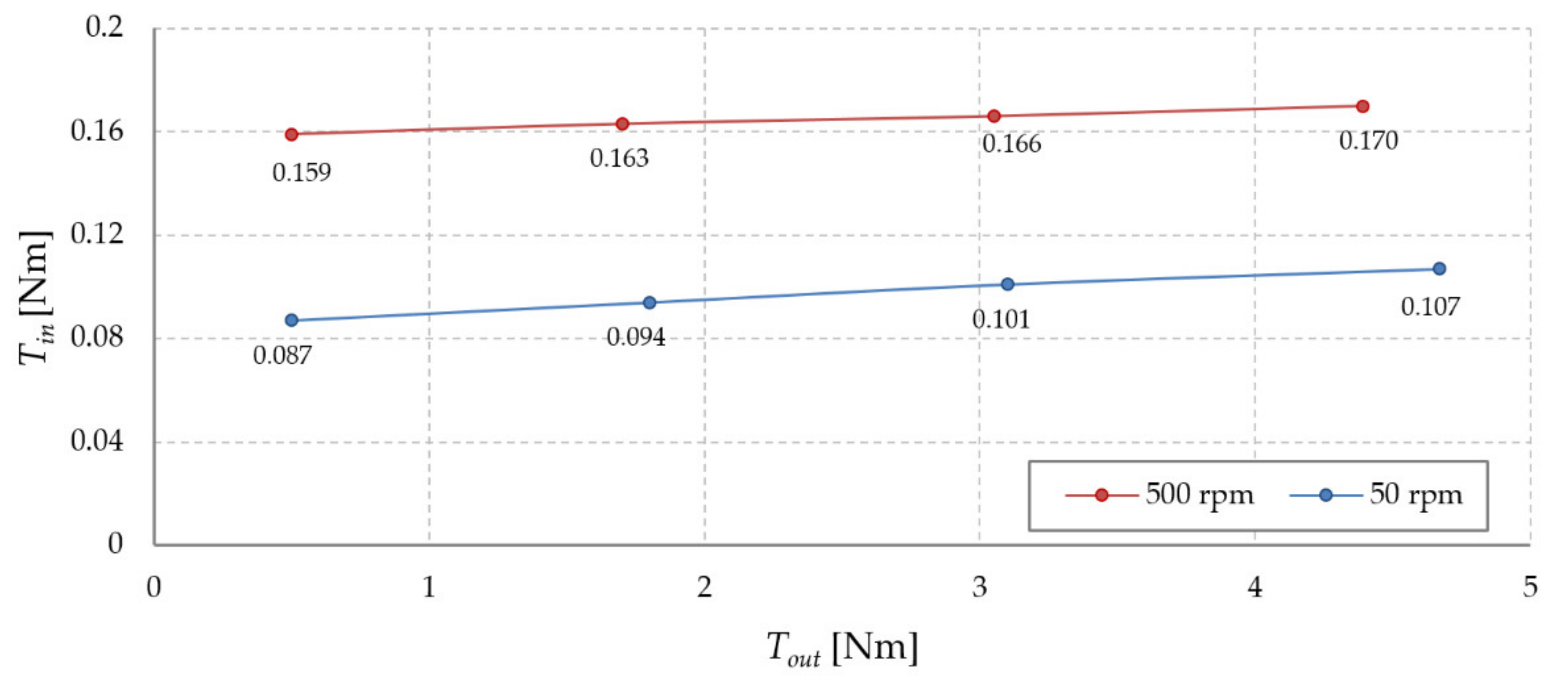
The impact of the load torque on the input torque of the studied MPG was examined next. The tests were carried out for two selected rotational speeds of the input shaft. The obtained characteristic is shown in
Figure 11.
As can be observed, when the load torque increases, so does the input torque. Assuming that the efficiency of the MPG is equal to 100%, the input torque should depend only on the gear ratio and for the studied MPG design should be 144 times less than the load torque. For example, when the load torque equals 3 Nm, the input torque should be 0.021 Nm. Due to frictional and eddy current losses, the measured values of the input torque are about five times higher than in the ideal case.
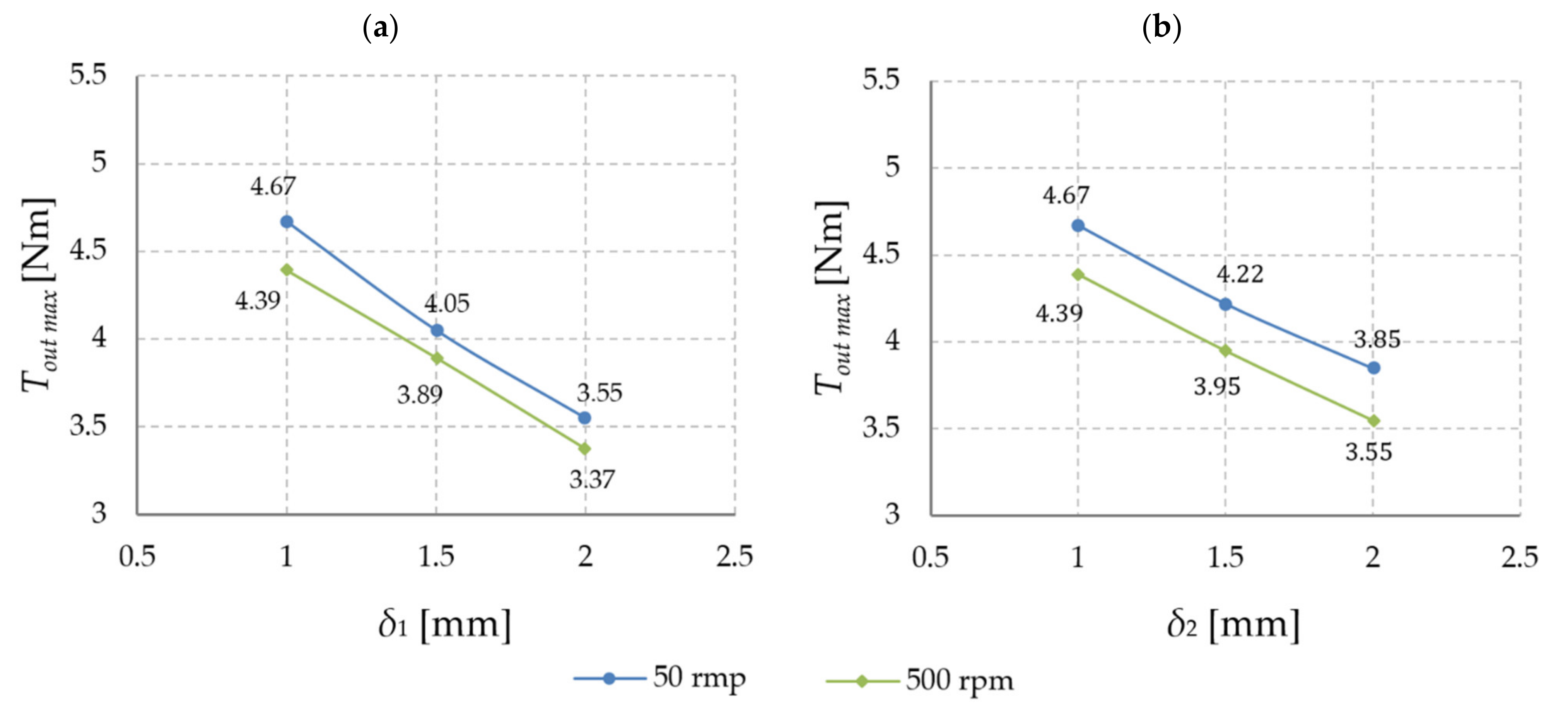
The maximum load torque that can be transmitted by the gear depends also on the air-gap lengths
δ1 and
δ2. When the length of the air gaps increases, the lower value of the torque can be transmitted because of the decreasing strength of the magnetic coupling; see the characteristics of the maximum load torque determined for two rotational speeds of the input shaft shown in
Figure 12.
When the rotational speed is low, the losses in the system are mainly generated by the bearings, whereas with an increase in the rotational speed, the contribution of the eddy current losses becomes more crucial, which also results in deterioration of the overall efficiency. An increase in the load torque leads to an increase in the load angle between movable elements (described in
Section 3) and, in consequence, to an increase in the magnetic torque, which influences the transmission efficiency. To illustrate the dependence of efficiency on rotational speed and load torque value, the efficiency map is shown in
Figure 13.
Next, the dependence of MPG efficiency on air-gap lengths was examined. The obtained gear efficiency vs. load torque characteristics determined for an input speed equal to 50 rpm and different values of air-gap lengths are shown in
Figure 14. Dotted vertical lines in
Figure 14 indicate the maximum load torque that the gear is able to transmit. It can be noticed that the air-gap lengths have a marginal impact on the slope of the efficiency characteristic; however, due to a change in
Tout max, the maximum value of efficiency undergoes significant changes.
Then, the dependencies of the magnetic torques affecting magnetically active components of the studied gear on the air-gap lengths
δ1 and
δ2, as well as load angles
β1 and
β2, were determined. The use of the developed numerical model of the magnetic field in the studied MPG allows studying the influence of each parameter independently. In this study, the influence of the discussed parameters of the magnetic circuit on values of the torques
Tout,
Tbase, and
Tin were examined. The obtained results are summarized in
Figure 15,
Figure 16 and
Figure 17.
It can be noticed that the output torque Tout depends on the length of the air gap, δ2, and the load angle β2 and is independent of β1 and δ1. As expected, the torque vs. load angle characteristic Tout = f (β2) is close to sinusoidal in shape. The dependence of the output torque Tout on the air-gap length δ2 shows that decreasing the value of the air-gap length increases the torque value at a given load angle.
It can also be noted that the torque acting on the immovable ring of the gear, Tbase, depends on the length of the air gap, δ1, and the load angle β1, while it is independent of β2 and δ2. Analogically to the output torque, the torque vs. load angle characteristic Tbase = f (β1) is sinusoidal in shape and Tbase, at a given load angle, increases with the shorter length of the air gap, δ1.
Regarding the dependence of the input torque Tin on the studied parameters, it can be seen that it is much more complex than for Tbase and Tout. The input torque depends on magnetic field distributions in both air gaps, and therefore, its value will be affected by both air-gap lengths δ1 and δ2 as well as both load angles β1 and β2.
Experimental verification of whether the developed numerical model of the magnetic field inside the gear is credible is a challenging task. In practice, the most technically difficult is to measure the dependence of the input torque on parameters of the magnetic circuit. To carry out such experiments, precise angular position sensors, as well as torque sensors, should be installed to accurately measure the angular positions of all movable elements of the studied gear. In the proposed approach, to mitigate the discussed problems and experimentally verify the proposed 3D FEM model, the angular positions of the input shaft of the prototype as well as the intermediate disk were fixed. Then, the angular position of the output shaft was forced by the external drive, and the output torque and the angular position of the shaft were measured, allowing one to determine the output torque vs. the internal load angle. The results of the simulations and measurements carried out are compared in
Figure 18. The achieved concordance between the results of the simulations and measurements proves satisfactory accuracy of the developed 3D FEM model. For all analyzed cases, the root-mean-square error does not exceed 10% of the maximum transmitted torque, which is considered a good agreement between the model and the experiment.
6. Conclusions
The concept of a two-stage magnetic precession gear was proposed and analyzed. A detailed analysis of the performance of the proposed gear was carried out using a developed numerical model of the magnetic field exploiting the FEM. To validate the developed model and study the gear efficiency, the prototype of an MPG with a 1/144 gear ratio was built and examined. The comparison results of the experiments and calculations were presented and discussed. The efficiency of the energy transmission via the studied gear was examined.
Due to lower exploitation of magnetically active materials, the proposed MPG cannot compete with a CMG in terms of torque density. Nevertheless, it should be noted that the proposed MPG enables one to obtain the value of a transmission ratio even higher than 1/1000, which is an unattainable value for other known types of magnetic gears.
The main conclusions from this research can be formulated as follows:
The concept of the proposed magnetic gear was validated via simulations and experiments.
The maximum obtained efficiency (approx. 30%) was limited by the maximum load torque carried by the gear as well as losses in the bearings and was related to the eddy current induced in the steel cores.
The maximum obtained efficiency of the MPG is a value comparable to the efficiency of mechanical two-stage precession transmission with face meshing [
21].
The shorter the lengths of the air gaps, the bigger the torque that the gear is able to carry because of the increasing strength of the magnetic coupling.
The model, determined by the developed numerical FEM, torques vs. load angle characteristics, can be further applied to develop a numerical model of the dynamic operation of the studied gear.
The authors will carry out further research on the development of the MPG, focusing on the analysis and optimization of its magnetic circuit to improve its performance, i.e., efficiency, torque density, as well as energy conversion quality, in terms of torque ripples. The coverage of the pole pitch by the magnet, as well as the magnet’s shape, will be optimized to increase the value of transmitted torque, allowing one to obtain an efficiency above 30%. The application of a soft magnetic composite as a core material as well as the segmentation of the permanent magnets are considered to reduce losses in the magnetic circuit. According to [
31,
32], the eddy current power loss in the permanent magnets decreases as a quadratic function of the number of circumferential permanent magnet segments. Simultaneously, efforts will be made to develop a numerical model of gear dynamics based on the obtained simulation results.


