Article

Effects of Two Pilot Injection on Combustion and Emissions in a PCCI Diesel Engine

1
School of Automotive and Traffic Engineering, Jiangsu University, Zhenjiang 212013, China
2
School of Business, Jinken College of Technology, Nanjing 210000, China
3
Shanghai FEV Powertrain Technology Company, Shanghai 200336, China
*
Author to whom correspondence should be addressed.
Energies 2021, 14(6), 1651; https://doi.org/10.3390/en14061651
Submission received: 10 February 2021 / Revised: 25 February 2021 / Accepted: 3 March 2021 / Published: 16 March 2021

Abstract

:
The effects of two pilot injections on combustion and emissions were evaluated in a single−cylinder turbocharged diesel engine, which operated in premixed charge compression ignition (PCCI) modes with multiple injections and heavy exhaust gas recirculation under the low load by experiments and simulation. It was revealed that with the delay of the start of the first pilot injection (SOI−P1) or the advance of the start of second pilot injection (SOI−P2), respectively, the pressure, heat release rate (HRR), and temperature peak were all increased. Analysis of the combustion process indicates that, during the two pilot injection periods, the ignition timing was mainly determined by the SOI−P2 while the first released heat peak was influenced by SOI−P1. With the delay of SOI−P1 or the advance of SOI−P2, nitrogen oxide (NOx) generation increased significantly while soot generation varied a little. In addition, increasing Q1 and decreasing the second pilot injection quantity (Q2) can manipulate the NOx and soot at a low level. The advance in SOI−P2 of 5 °CA couple with increasing Q1 and reducing Q2 was proposed, which can mitigate the compromise between emissions and thermal efficiency under the low load in the present PCCI mode.

1. Introduction

With increasing concerns about fossil fuel consumption, environmental protection, and stricter emission regulations, the production of engines urgently needs higher fuel conversion efficiency and lower emissions. Diesel engines are widely used in industry and traffic due to the advantages such like high heat efficiency and low fuel consumption. Nevertheless, high nitrogen oxides (NOx) and soot emissions have been the most prominent problem in diesel engines, so the newly developed diesel engine should have lower soot and NOx emissions when maintaining high thermal efficiency. Another challenge is the difficulty in simultaneously reducing the two types of emission, for which there is a trade-off [1,2].
At present, the main measures taken include multi-stage injection, high injection pressure, micro injector orifices, and new clean alternative fuels. Fraioli et al. [3] evaluated the feasibility of applying methane-diesel dual-fuel to a light-duty engine using one-stage and two-stage injection strategies under medium and high engine load, and found that simulated predicted values are reasonably consistent with experimental values. Mueller et al. [4] put forward the concept of ducted fuel injection for a direct injection engine, which is an effective approach for mitigating the compromise between harmful pollutants and thermal efficiency. Homogeneous charge compressed ignition (HCCI) combustion has been widely researched in order to reduce soot and NOx emissions and improve the thermal efficiency. However, its combustion rate and combustion phase are difficult to control, and the diluted mixing characteristics lead to a narrow operating range [5,6,7]. Different from the complete homogeneous charge in HCCI modes, premixed charge compression ignition (PCCI) operates with larger proportions of premixed charge than traditional model, and in the meantime it deploys multiple injection strategies and exhaust gas recirculation (EGR) rates to greatly increase the controllability of combustion rate [8,9]. The effect of EGR in a diesel engine adopting the PCCI mode has been discussed by Jain et al. [10]. It was reported that a satisfactory two-stage injection timing coupled with an appropriate EGR rate can achieve a good compromise in improving engine performance and reducing emissions. Lu et al. [11] also found that EGR coupled with multi-stage injection can simultaneously reduce soot and NOx emissions. Regarding multi-stage injection strategies, after the comparison between the single and two stage injections, Yu et al. [12] discovered a better effect on combustion and emission characteristics which can be achieved by using two-stage injection strategies. A similar conclusion was obtained in the work of Park et al. [13], in which they adopted one-stage and two-stage injection strategies to reduce HC and CO emissions in a PCCI diesel engine. Cao et al. [14] demonstrated that in a two-stage injection strategy, the second injection flame propagated faster, and the soot concentration was more evenly distributed. On the side, the impacts of the injection parameters on fuel combustion have also been investigated. Yin et al. [15] found that, in comparison to one-stage injection strategy, the two-stage injection strategy with suitable injection parameters can cut emissions. He et al. [16] reported that the emissions of soot and NOx simultaneously decreased with the advance of the pilot injection timing. Fajri et al. [17] concluded that prolonging the combustion duration had a positive effect on the combustion process and the reduction of NOx emissions. Hence, the combination of an appropriate multi-stage injection strategy and EGR can play a significant part in lessening soot and NOx emissions in PCCI combustion mode [18,19,20]. Besides, the gasoline fuel also can be an available solution for the next emissions legislation targets since the pollutant emissions will be reduced drastically, and the partially premixed combustion process employing gasoline blend can allow us to reduce soot and NOx emissions and improve the thermal efficiency [21].
A variety of fuel injection strategies such as pilot-main injection, main-post injection, and pilot-main-post injection has been adopted to explore the impacts of injection strategies on performance and harmful pollutants [22,23,24]. However, the pilot-pilot-main injection strategy has been less put into effects. In addition, compared with the high load, the lower fuel amount can lead to the low local concentration and incomplete combustion of fuel-air mixtures in the cylinder, and the increase of NO and soot emissions under the low load in normal PCCI mode [25]. Hence, in the present study, the authors studied the combustion process, NO, and soot generation using pilot-pilot-main injection strategy under the high EGR rate of 44% and low IMEP of 0.44 MPa at 1900 rpm through experiments to broaden the load range of PCCI mode. Moreover, to further mitigate the compromise between harmful pollutants and thermal efficiency, the timing and proportion of the two pilot injections were adjusted through simulation software to probe into the performance and harmful pollutants characteristics of the PCCI mode.

2. Methodology

2.1. Experimental Facility

The experiment was brought into operation on a high-pressure common-rail single-cylinder diesel engine originating from the 4-cylinder Daimler OM646 diesel engine. The detailed test prototype parameters are shown in Table 1, and the experimental facility is presented in Figure 1. In order to meet the European V and stricter emission standards, the high-pressure common-rail system was equipped to flexibly dominate the number of injections and the injection pulse width. The indicated mean effective pressure (IMEP) was used to assess engine performance. A heavy EGR rate of 44% was coupled with the intake supercharging to achieve the diesel PCCI combustion mode.
The main test equipment is displayed in Table 2. The in-cylinder pressure was ascertained by a pressure sensor (Model 6043ASP, Germany). The engine crank angle was recorded by an encoder. The heat release attributes were obtained by using a combustion analyzer IndiCom software. NOx and soot emissions were measured by a chemiluminescence analyzer and an AVL439 optical Hartridge opacimeter, respectively.
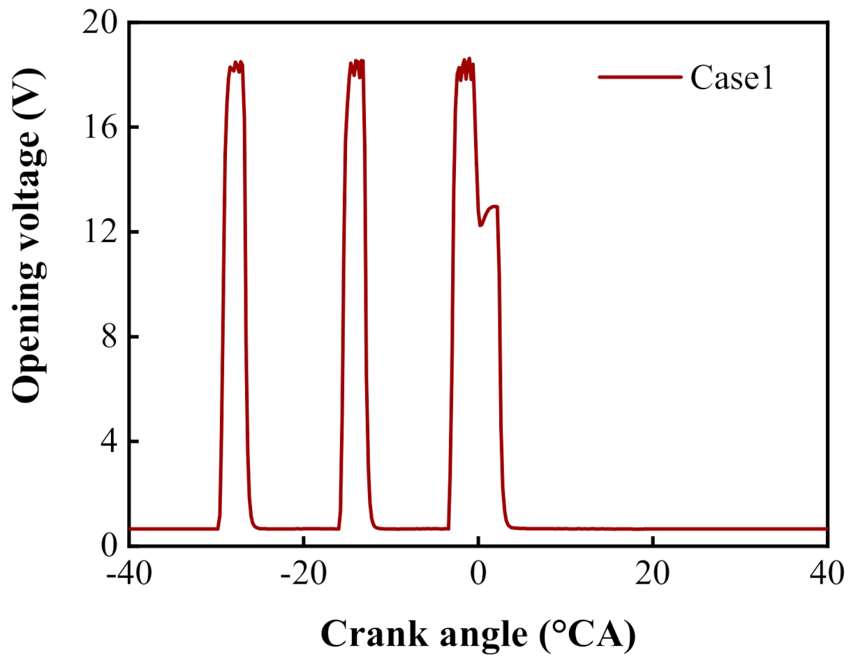
At the mode of the IMEP of 0.44 MPa at 1900 rpm, the parameters of the fuel supply system are shown in Figure 2. Figure 2 indicates the opening timing of the solenoid valve and injection pulse width under the fuel injection, in which the three pulses of solenoid valve are two pilot injection and main injection.

2.2. Modeling

The Pressure-Implicit with Splitting of Operators (PISO) algorithm was implemented by the AVL Fire software to simulate the pressure-velocity coupling process [26]. In order to accurately describe the physical and chemical changes of working medium in a real PCCI diesel engine [27], the sub-models, including turbulence [28], spray impingement [29], combustion [30], and emission [31] models were adopted, which are shown in Table 3.
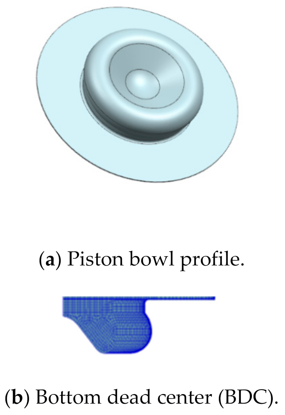
The piston bowl profile is shown in Figure 3a. Since the diesel injector used in the research has seven equally distributed orifices, the calculation was carried out using a seventh of the combustion chamber. The computational grids applied in this study were composed of approximately 21,840 and 17,840 cells, respectively, as shown in Figure 3b,c. The simulation was implemented with a bounded system, from the intake valve closing at 122 °CA to the exhaust valve opening at 116 °CA.
The initial calculation conditions and boundary parameters are shown in Table 4, among which the simulated initial temperature, initial pressure, initial fuel temperature, and EGR were obtained based on experiments. The opposite cut surface of the sector was used as the cycle boundary. The cylinder wall, cylinder head, and the top of the combustion chamber were used as fixed wall surfaces. The initial temperatures around chambers were endowed with experienced data.

2.3. Operating Methodology and Model Validation

Fuel injection schemes are shown in Table 5. Based on Case1, Case2 tunes the first and second pilot injection timings, and Case1-1 and Case1-2 change the fuel mass of the two pilot injection. Case1-3 adjusts the fuel amount and the second pilot injection timing of the two pilot injection simultaneously.
The simulation model established in this article was verified at experimentally operation model at 0.44 MPa, of which the specific parameters are presented in Table 6. Figure 4 manifests the validation of the simulated and experimental values of cylinder pressure, heat release rate (HRR), NO, and soot. It seems that the profile of simulated cylinder pressure, HRR, NO, and soot processed well with the experimental one, only having a little larger outbreak pressure. It can be explained as, in a real engine operation, there were more practical losses. The error between the simulated pressure and measured one was found to be basically less than 5%, which indicates the simulation model can be used for the research schemes of various pilot injection parameters.

3. Results

3.1. Effects of Pilot Injection Timing

3.1.1. Characteristic of Heat Release

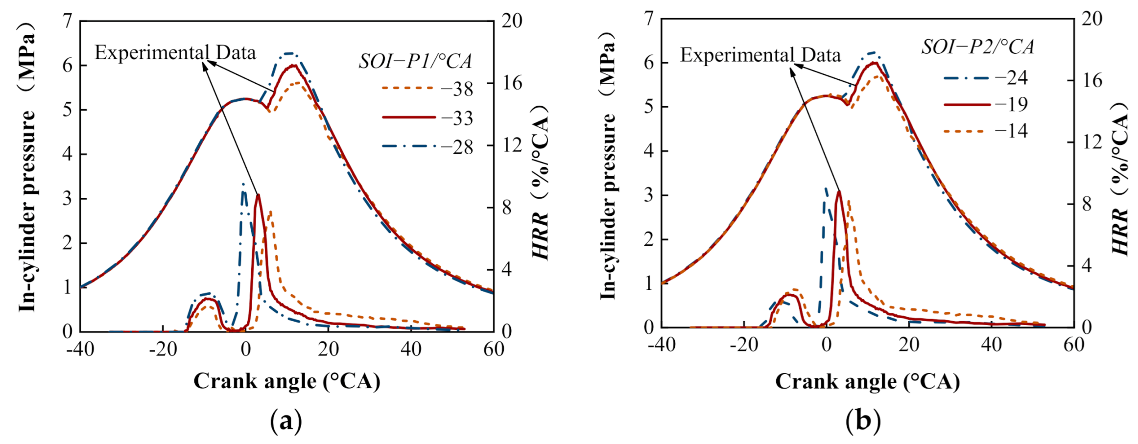
The pressure and HRR at diverse SOI−P1 schemes and SOI−P2 schemes are, respectively, shown in Figure 5, in which the experimental data have been indicated. It can be easily found that the second peak pressure and maximum HRR increased with delaying SOI−P1. Generally, after the first pilot fuel was injected into the cylinder, it was difficult to form the ignition area due to factors such as insufficient fuel amount, fuel-air diffusion, and lower temperature. Hence, the ignition and the spread of flame take placed after the second pilot injection [32]. With the delay of SOI−P1, a favorable atmosphere of high pressure, high temperature, and strong turbulent was developed in cylinder, which made the first pilot fuel mix well with air to form combustible mixtures. The combustible mixtures formed by the first pilot fuel and the second pilot fuel were automatically ignited under appropriate conditions and released more heat. Hence, the increase in heat release from pilot fuel made the temperature and pressure rose significantly before the main injection. In addition, more combustible mixtures can be formed after the main injection fuel, enhancing the combustion temperature. Owing to the combined heat released by the pilot fuel and main injection, the energy forming the main injection fuel and air mixtures was enhanced. Therefore, the mixing rate was increased, which resulted in an acceleration in heat release and the advance in main combustion.
With the advance SOI−P2, the pressure peak and maximum HRR gradually increased, and the phase advanced smoothly. The second pilot fuel injection earlier with advancing SOI−P2 brought about the advance of the pilot fuel ignition timing. Simultaneously, more incompletely burnt mixtures formed by the pilot fuel participated in the subsequent main combustion. The former heat release coupled the main combustion, which enhanced the turbulences and accelerated the heat release of the main combustion.
The bulk gas temperature in cylinder for different SOI−P1 schemes and SOI−P2 schemes are presented in Figure 6. More pilot fuel was involved in burning the combustion in time due to the postponed SOI−P1, which intensified the formation of the fuel-air mixture and accelerated the heat released from the main combustion. As a result, with the delay of SOI−P1, the bulk gas temperature rose accordingly, and the differences in the maximum combustion temperature reached 100 K. Conversely, the bulk gas temperature peak gradually dropped with delaying the SOI−P2. With the remaining SOI−P1 unchanged and delaying SOI−P2, the ignition timing of the pilot fuel was postponed, which resulted in more pilot fuel burning in the initial stage. Consequently, the heat release in the main combustion slowed down and the combustion duration was prolonged, resulting in further significant low-temperature combustion effects. The maximum temperature was dropped by 80 K in Case3, with the delay of SOI−P2.

3.1.2. Combustion Features at Particular Moments

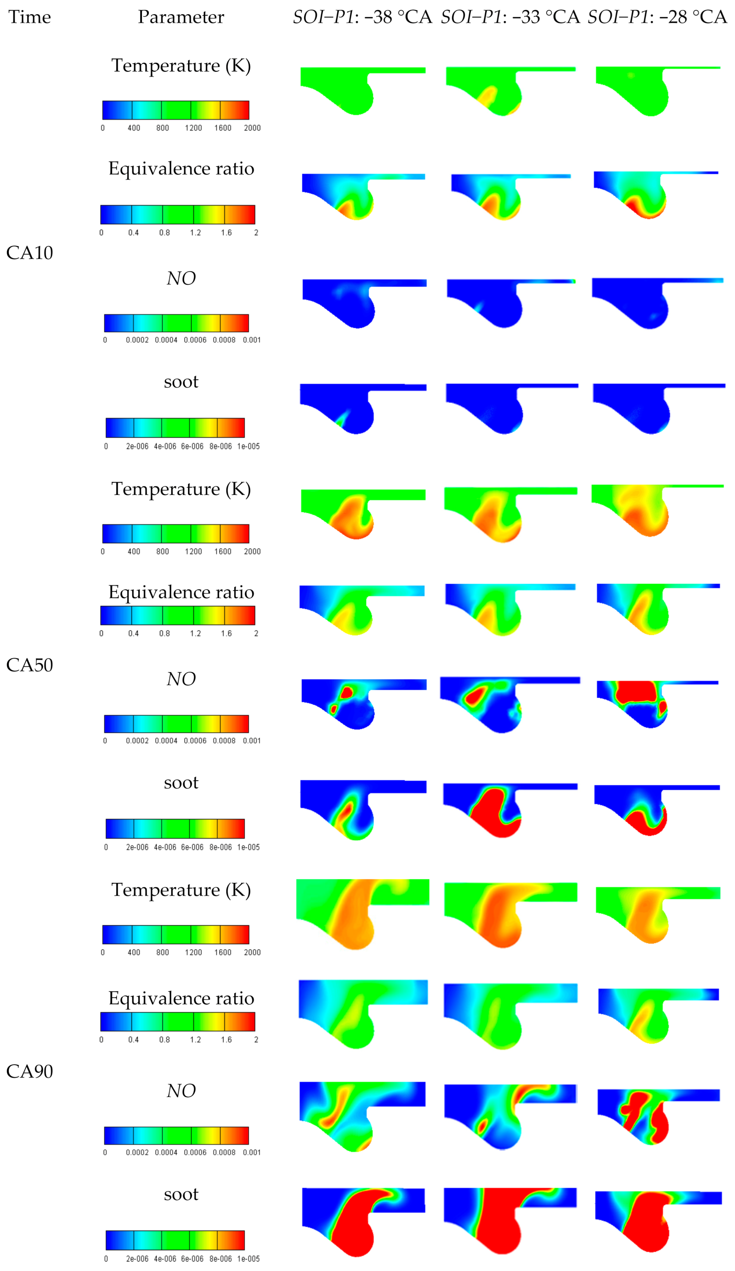
Figure 7 displays the temperature, fuel-air equivalence ratio, NO, and soot graphs for diverse SOI−P1 schemes of Case2. Only the combustion features for different SOI−P1 schemes are shown in this paper since the combustion features for different SOI−P1 schemes and SOI−P2 schemes are similar. Analysis are focused on three typical heat release timings, namely CA10, CA50, and CA90 (Appendix A). In the initial combustion, for the SOI−P1 of −38 °CA and −33 °CA, a small amount of NO was generated because the high temperature and equivalence ratio zones were mainly concentrated in the bottom of the combustion chamber. However, for the SOI−P1 of −28 °CA, more NO was generated due to the more high-temperature zones formed at the edge of rich mixtures. At the CA50 moment or later, the mixtures diffused quickly with the assistance of the squeezed flows. In addition, the temperature rose rapidly with the ongoing combustion at areas of suitable fuel-air equivalence ratio. NO generation corresponded well to those scorching areas with proper lean mixtures. With the advance of SOI−P1, the generation of NO reached its minimum at the SOI−P1 of −38 °CA, which was caused by the low reaction temperature as a whole. In general, the proper advance of SOI−P1 was beneficial for the NO reduction.
The soot generation regions appeared fine accordance with the fuel-air equivalence ratio. Firstly, soot was generated near the combustion chamber wall. This can be attributed to the relatively higher fuel-air equivalence ratio and the nethermore balk gas temperature. At the CA50 moment, the generation of soot was concentrated near the cylinder wall and in the concave with high fuel-air equivalence ratio. Working volume expanded continuously with the proceeding of combustion, which resulted in the rapid diffusion of mixtures. Thus, the mixtures became lean. The flame gradually diffused to the whole chamber as the piston moved down, when the high-temperature zones coincided with the fuel concentration area, resulting in the increase of soot formation zones. With the advance of SOI−P1, the generation of soot slightly reduced under combined effects of the temperature and fuel-air mixtures. At the SOI−P1 of −38 °CA, the soot generation at CA50 and CA90 moments dropped to its minimum, compared with the other two schemes, respectively. It can be explained as the advance of SOI−P1 led to a prolongation in the main combustion duration, the delay of the CA50 and CA90 moments and the enough large working volume, which was more suitable for fuel-air diffusion and combustion.

3.1.3. Emission Characteristics

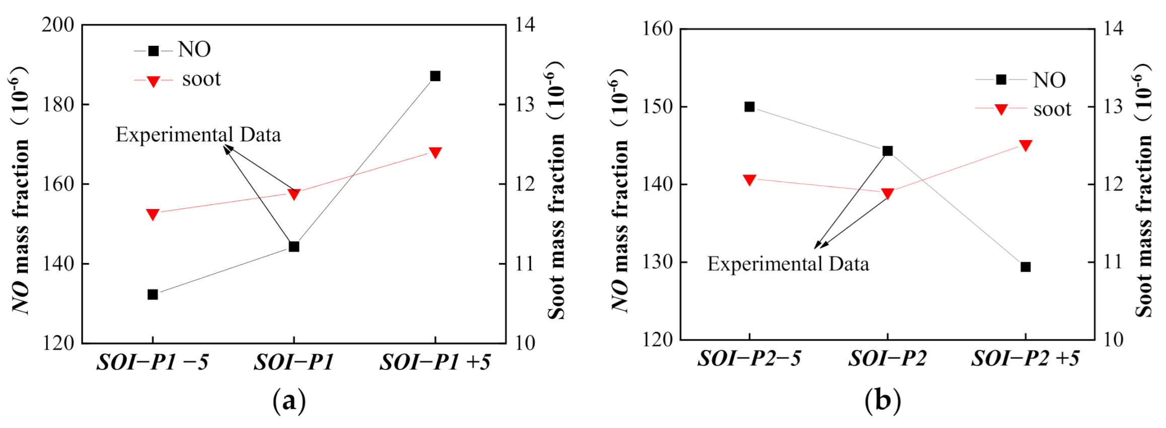
The generation of NO and soot in cylinder for SOI−P1 injection schemes are presented in Figure 8a. It was worth nothing that NO generation kept good agreement with the bulk gas temperature, as shown in Figure 6a. With the delay of SOI−P1, the generation of NO increased since more mixtures burnt at that moment and released a large amount of heat, which led the bulk gas temperature rise. The multiple injections made the fuel and air mix better, which beneficially repressed the generation of soot. Generally, the terminal soot was deeply dependent on not only the distribution of fuel-air equivalence ratio, but also the bulk gas temperature. As shown in Figure 6b, delaying SOI−P1 increased the maximum combustion temperature which promoted the oxidation of soot, however, it also decreased the post combustion temperature rapidly which restrained the oxidation of soot slightly. On the whole, the final soot was increased with the delay of SOI−P1.
Figure 8b depicts the generation of NO and soot in cylinder for the SOI−P2 injection schemes. The generation of NO was generally determined by the bulk gas temperature and oxygen concentration in the reaction area. With the delay of SOI−P2, the generation of NO was reduced. At different injection schemes, the generation of NO coincided conformably to the temperature with referring to Figure 6, which indicates that the temperature had a decisive impact on the generation of NO. Advancing SOI−P2 raised the reaction temperature, which reinforced the soot oxidation rate, and shortened the combustion duration, which impaired the diffusion and mixing of fuel with air. Owing to these two aspects, there was only a little change in the final soot generation.

3.2. Effect of Two Pilot Injection Proportions

3.2.1. Characteristic of Heat Release

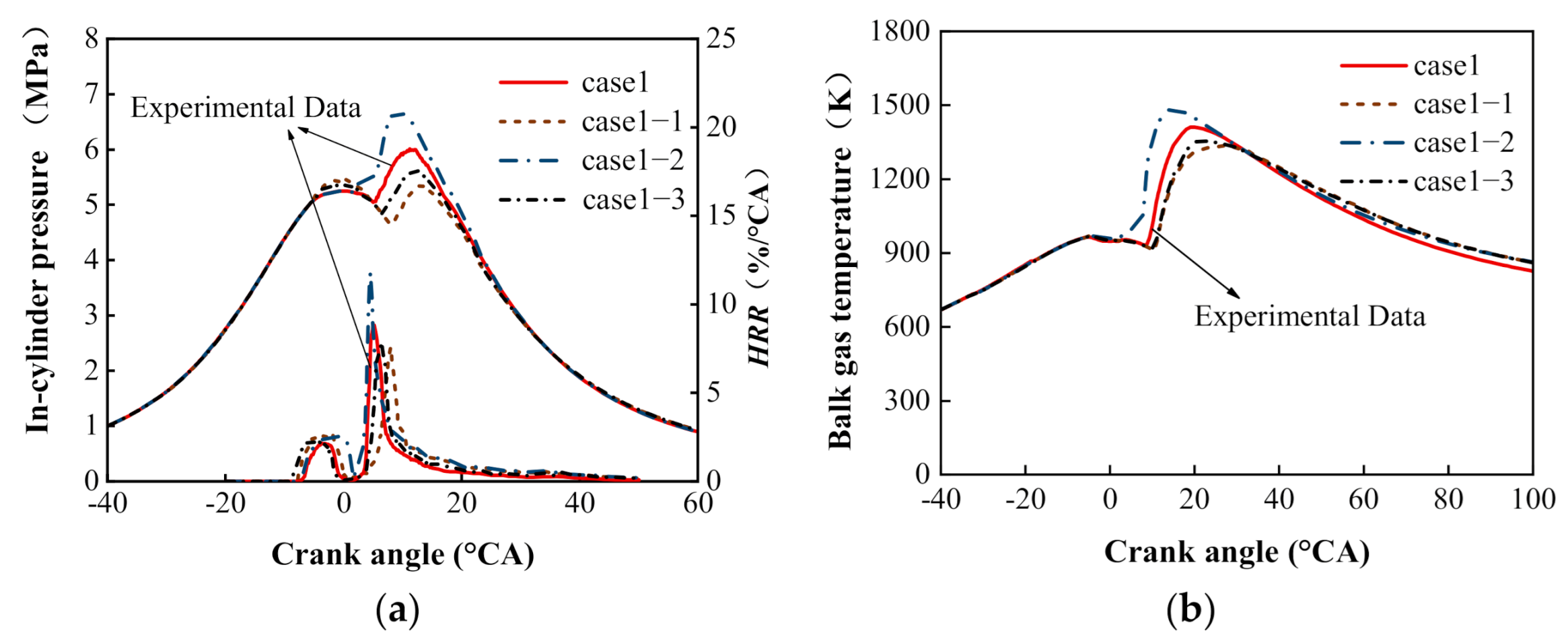
The cylinder pressure and HRR at diverse pilot injection ratio schemes are, respectively, shown in Figure 9a, which contains experimental data. Increasing Q1 and decreasing Q2, the first peak of cylinder pressure and HRR increased, while the primary peak declined. On the one hand, more mixtures formed by the pilot fuel burnt and released heat in the initial combustion, raising the first peak of cylinder pressure. On the other hand, the countering unburnt mixtures were reduced, which decreased the mixing rate of fuel with air, the burst pressure and HRR in the main injection. In contrast, the pressure and HRR of the main combustion increased and the heat release phase advanced in Case1-2. It can be explained as the unburnt mixtures mainly stemmed from the second pilot fuel combined with the main combustion since Q2 was greater than Q1, which brought about more intense turbulences and accelerated the mixing rate of fuel with air as well. Compared with Case1-1, the main pressure peak rose in Case1-3. This was due to the fact that more pilot fuel participated in the main combustion when ahead of SOI−P2, resulting in faster main heat release. Similarly, more unburnt mixtures originated from the pilot fuel participated in the subsequent main combustion, leading to an increase in the main heat release peak.
The temperature decreased, and the phase was delayed with the reduction of Q2, as shown in Figure 9b. At the initial combustion, when the pilot injection proportion was 1:4, the bulk gas temperature rose rapidly because of the greater HRR. Although a greater Q1 was more favorable to fulfilling low-temperature combustion, the thermal efficiency was reluctantly reduced. Hence, coupled with increasing Q1 and reducing Q2, the scheme of advancing SOI−P2 was adopted in Case1-3 to remedy this issue.

3.2.2. Combustion Features at Particular Moments

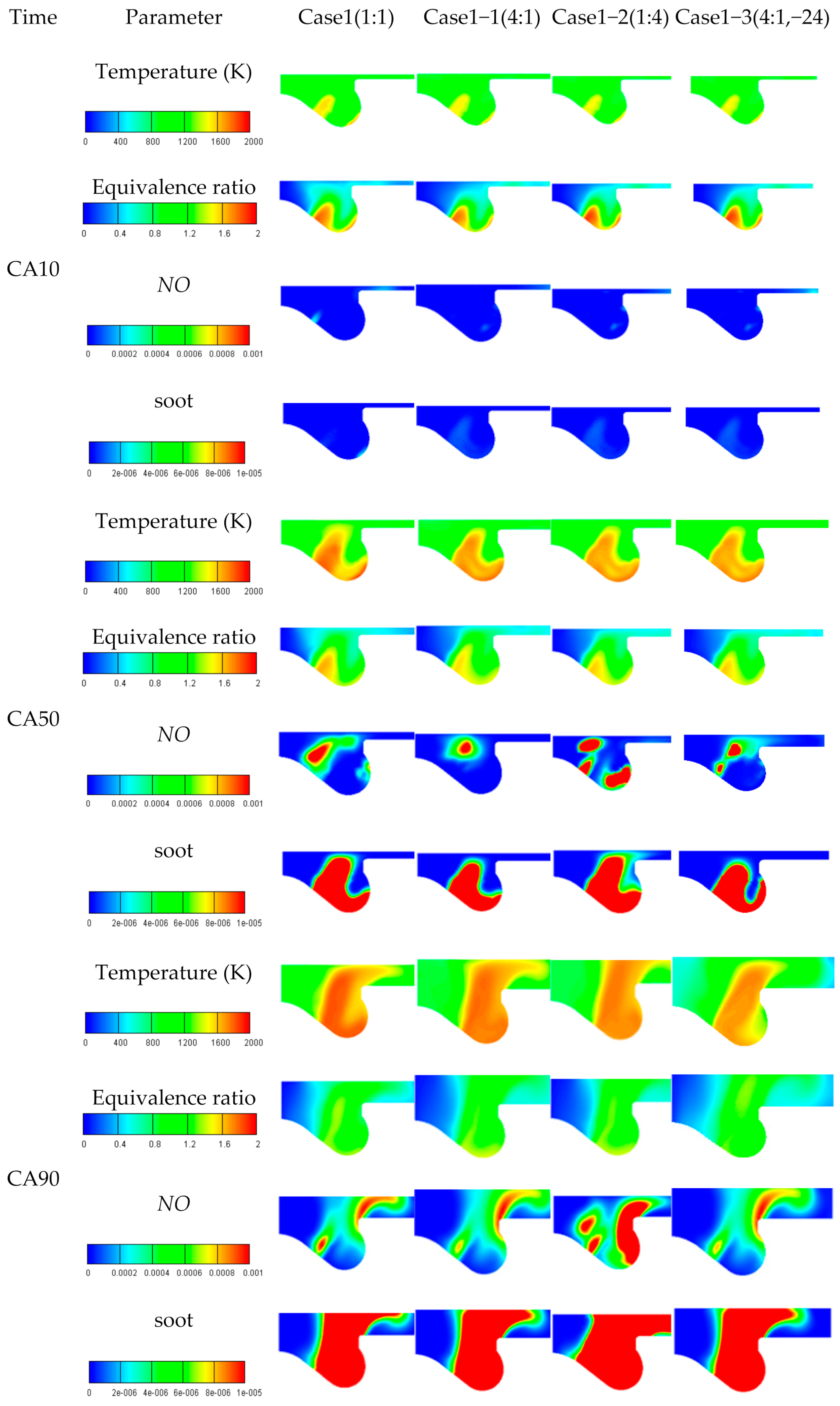
Temperature, fuel-air equivalence ratio, NO, and soot emissions graphs for diverse pilot injection ratio schemes are displayed in Figure 10. Analysis is focused on three typical heat release timings, namely CA10, CA50, and CA90. From the detailed combustion proceeding with the heat release timing of CA10, marginally fuel-air mixtures accumulated at the bottom of the concave. At this moment, high temperature zones also emerged in the local area of the concave wall with rich mixtures. With reference to emissions, a little NO emission was generated, which was mainly diffused at the bottom of the concave and in the wall zone of high temperature. Tiny soot was generated at the bottom of the concave only in Case1 because of its high local temperature. Compared with the CA10 moment, the first pilot injection proportion increased at the CA50 moment, which brought about the relatively light color on the temperature and the fuel concentration area. This demonstrated the relatively low local temperature and lean mixture zones at the CA50 moment. It was worth mentioning that NO emission was mainly distributed in the areas with high temperature and low equivalence ratio. Thus, NO generation lessened since the rise of the first pilot injection proportion. However, in Case1-3, partial NO concentration zones increased slightly with a growing tendency in the first pilot injection proportion and the advance of SOI−P2. At the CA90 moment, the cylinder volume increased quickly. Correspondingly, mixtures diffused speedily and thus the fuel-rich area reduced, which resulted in the improvement on the mixture uniformity and even the quick spread of flame spread to the whole concave. With the increase of high-temperature regions, NO gradually diffused to the middle and upper concave, and the zone near the concave wall with a small amount of fuel-air mixtures. NO generation dropped with the increase of first pilot injection proportion. Soot generation was in agreement with the distribution of the high temperature and fuel-rich zones.

3.2.3. Emission Characteristics

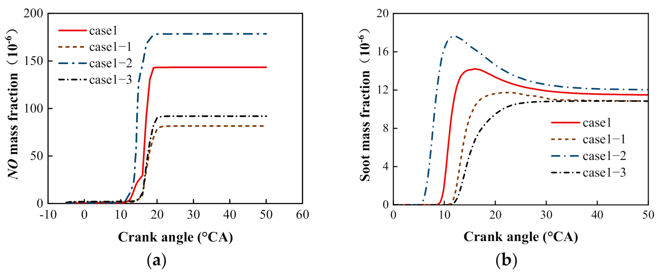
The NO and soot mass fraction profile for diverse pilot injection ratio schemes are shown in Figure 11. Figure 11a demonstrates that NO generation, which was controlled by the bulk gas temperature, increased, and its phase advanced with the increase of Q2. Generally speaking, increasing Q2 was analogous to the function of advancing the main injection or increasing the main fuel injection. Thus, compared with Case1, heat release was more focused and its phase was near the top dead center (TDC) in Case1-2, which brought about the high temperature and the increase of NO generation. In addition, with the increase of Q2, a lot of fuel cannot burn adequately before the main injection began. Hence, large amounts of fuel in the main injection were injected into the pilot combustion area, and it didn’t mix well with air under the high temperature and anoxic condition, leading to a rise in soot generation. Compared with Case1, increasing Q1 lessened the generation of NO and soot, but it was not conducive to the thermal efficiency in Case1-1. In consequence, on the basis of increasing Q1 and reducing Q2, the scheme of advancing SOI−P2 was proposed in Case1-3, which reduced the emission of NO and soot and improved the combustion process in cylinder referring to Figure 9 and Figure 10.

4. Discussion

Compared with the high load, the lower fuel amount can lead to the low local concentration and incomplete combustion of fuel-air mixtures in the cylinder, and the increase of NO and soot emissions under the low load in normal PCCI mode. Hence, the effects of two pilot injection timings and injection ratios on the emission and combustion using pilot-pilot-main injection strategy under the high EGR rate of 44% and low IMEP of 0.44 MPa at 1900 rpm were researched by experiments and simulation to broaden the load range of the present PCCI mode, and the following conclusions were gained.
With remaining SOI−P2 unchanged and advancing SOI−P1, the heat release in the two pilot injection periods decreased. With remaining SOI−P1 unchanged, the ignition took place early with advancing SOI−P2. The in-cylinder pressure, HRR and temperature peak decreased and their corresponding phases were postponed with the advance of SOI−P1, which was contrary to that of advancing SOI−P2. In addition, with the advance of SOI−P1 or SOI−P2, respectively, NO emissions presented fine accordance with the temperature peak, while the soot generation regions were consistent with the fuel-air equivalence outline.
Increasing Q1 and reducing Q2 can effectively restrain the generation of NO and soot. However, the pressure, HRR, and combustion temperature peak were all decreased. It can be found from the foregoing analysis that the pressure, HRR, and combustion temperature peak were all increased with the advance of SOI−P2. Hence, the advance in SOI−P2 of 5 °CA coupled with increasing Q1 and reducing Q2 was proposed in Case1-3, which can improve the thermal efficiency while maintaining little change in emissions under the low load in the present PCCI mode. In summary, effects of adjusting two pilot injection timings and proportions simultaneously in Case1-3 on combustion were evaluated based on simulation works, which can provide valuable references for mitigating the compromise between emissions and thermal efficiency under the low load in the present PCCI mode.

5. Conclusions

A scheme of the advance in SOI−P2 of 5 °CA coupled with increasing Q1 and reducing Q2 was proposed in Case1-3, which can improve the thermal efficiency while maintaining little change in emissions under the low load in the present PCCI mode. Future research activities will be focused on the effects of using new clean alternative fuels, such as dimethyl carbonate (DMC) and biodiesel, as blending components with diesel, respectively, on combustion and emissions in the PCCI diesel engine, in order to further reduce emissions and meet the next emissions legislation targets.

Author Contributions

Conceptualization, D.M. and Q.Y.; methodology, D.M. and Q.Y; software, D.M. and Q.Y.; validation, D.M. and Q.Y.; formal analysis, D.M., Q.Y., Z.Z., S.Y., and L.T.; investigation, D.M., Q.Y., Z.Z., S.Y., and L.T.; resources, D.M.; data curation, D.M., Q.Y., Z.Z., S.Y., and L.T.; writing—original draft preparation, Q.Y.; writing—review and editing, D.M.; visualization, D.M., Q.Y., Z.Z., S.Y., and L.T.; supervision, D.M., Q.Y., Z.Z., S.Y., and L.T.; project administration, D.M., Q.Y., Z.Z., S.Y., and L.T.; funding acquisition, D.M. All authors have read and agreed to the published version of the manuscript.

Funding

This research was funded by the National Natural Science Foundation of China (No. 51876082 and No. 51876133).

Institutional Review Board Statement

Not applicable.

Informed Consent Statement

Not applicable.

Data Availability Statement

All data are presented in this article. Data sharing is not applicable to this article.

Conflicts of Interest

The authors declare no conflict of interest.

Appendix A

Table A1. The abbreviations used in this manuscript.
QMMain injection quantity
TDCTop dead center
BDCBottom dead center
CA10When the accumulated HRR attained ten percent of the total HRR
CA50When the accumulated HRR attained fifty percent of the total HRR
CA90When the accumulated HRR attained ninety percent of the total HRR
HRRHeat release rate

References

  1. Landau, D.; Novack, L.; Yitshaksade, M. Nitrogen dioxide pollution and hazardous household environment: What impacts more congenital malformations. Chemosphere 2015, 139, 340–348. [Google Scholar] [CrossRef] [PubMed]
  2. Pedersen, M.; Andersen, Z.J.; Stafoggia, M. Ambient air pollution and primary liver cancer incidence in four European cohorts within the ESCAPE project. Environ. Res. 2017, 154, 226–233. [Google Scholar] [CrossRef] [PubMed]
  3. Fraioli, V.; Beatrice, C.; Blasio, G.D.; Belgiorno, G.; Migliaccio, M. Multidimensional Simulations of Combustion in Methane-Diesel Dual-Fuel Light-Duty Engines. In Proceedings of the SAE World Congress Experience (WCX 17), Detroit, MI, USA, 4–6 April 2017. [Google Scholar] [CrossRef]
  4. Mueller, C.J.; Nilsen, C.W.; Ruth, D.J.; Gehmlich, R.K.; Pickett, L.M.; Skeen, S.A. Ducted fuel injection: A new approach for lowering soot emissions from direct-injection engines. Appl. Energy 2017, 204, 206–220. [Google Scholar] [CrossRef]
  5. Singh, A.P.; Agarwal, A.K. Combustion characteristics of diesel HCCI engine: An experimental investigation using external mixture formation technique. Appl. Energy 2012, 99, 116–125. [Google Scholar] [CrossRef]
  6. Singh, G.; Singh, A.P.; Agarwal, A.K. Experimental investigations of combustion, performance and emission characterization of biodiesel fueled HCCI engine using external mixture formation technique. Sustain. Energy Technol. Assess. 2014, 6, 116–128. [Google Scholar]
  7. Sharma, T.K.; Rao GA, P.; Murthy, K.M. Homogeneous Charge Compression Ignition (HCCI) Engines: A Review. Arch. Comput. Methods Eng. 2015, 23, 1–35. [Google Scholar] [CrossRef]
  8. Kiplimo, R.; Tomita, E.; Kawahara, N.; Yokobe, S. Effects of spray impingement, injection parameters, and EGR on the combustion and emission characteristics of a PCCI diesel engine. Appl. Therm. Eng. 2012, 37, 165–175. [Google Scholar] [CrossRef]
  9. Torregrosa, A.J.; Broatch, A.; García, A.; Mónico, L.F. Sensitivity of combustion noise and NOx and soot emissions to pilot injection in PCCI Diesel engines. Appl. Energy 2013, 104, 149–157. [Google Scholar] [CrossRef] [Green Version]
  10. Jain, A.; Singh, A.P.; Agarwal, A.K. Effect of split fuel injection and EGR on NOx and PM emission reduction in a low temperature combustion (LTC) mode diesel engine. Energy 2017, 122, 249–264. [Google Scholar] [CrossRef]
  11. Lu, Y.; Yu, W.; Su, W. Using Multiple Injection Strategies in Diesel PCCI Combustion: Potential to extend Engine Load, Improve Trade-Off of Emissions and Efficiency; SAE Technical Papers 2011-0148-7191; SAE International: Warrendale, PA, USA, 2011; ISSN 0148-7191. [Google Scholar]
  12. Yu, H.; Liang, X.; Shu, G.; Wang, Y.; Sun, X.; Zhang, H. Numerical investigation of the effect of two-stage injection strategy on combustion and emission characteristics of a diesel engine. Appl. Energy 2018, 227, 634–642. [Google Scholar] [CrossRef]
  13. Park, Y.; Bae, C. Effects of Single and Double Post Injections on Diesel PCCI Combustion; SAE Technical Papers 2013-01-0010; SAE International: Warrendale, PA, USA, 2013; ISSN 0148-7191. [Google Scholar]
  14. Cao, J.; Leng, X.; He, Z.; Wang, Q.; Shang, W.; Li, B. Experimental study of the diesel spray combustion and soot characteristics for different double-injection strategies in a constant volume combustion chamber. J. Energy Inst. 2019, 93, 335–350. [Google Scholar] [CrossRef]
  15. Yin, B.; Wang, J.; Yang, K.; Jia, H. Optimization of EGR and split injection strategy for light vehicle diesel low temperature combustion. Int. J. Automot. Technol. 2014, 15, 1043–1051. [Google Scholar] [CrossRef]
  16. Xuan, T.; He, Z.; Jiang, Z.; Yan, Y. Study on effect of fuel injection strategy on combustion noise and exhaust emission of diesel engine. Therm. Sci. 2013, 17, 81–90. [Google Scholar]
  17. Fajri, H.R.; Jafari, M.J.; Shamekhi, A.H.; Jazayeri, S.A. A numerical investigation of the effects of combustion parameters on the performance of a compression ignition engine toward NOx emission reduction. J. Clean. Prod. 2017, 167, 140–153. [Google Scholar] [CrossRef]
  18. Choi, H.; Lee, J.; Hong, K.; Lee, S.; Choi, S.; Yu, S.; Min, K. Comparison of the effects of multiple injection strategy on the emissions between moderate and heavy EGR rate conditions: Part 2—Post injections. J. Mech. Sci. Technol. 2013, 27, 2217–2223. [Google Scholar] [CrossRef]
  19. Park, S.; Lee, K.S.; Park, J. Parametric study on EGR cooler fouling mechanism using model gas and light-duty diesel engine exhaust gas. Energies 2018, 11, 3161. [Google Scholar] [CrossRef] [Green Version]
  20. D’Ambrosio, S.; Ferrari, A. Potential of multiple injection strategies implementing the after shot and optimized with the design of experiments procedure to improve diesel engine emissions and performance. Appl. Energy 2015, 155, 933–946. [Google Scholar] [CrossRef]
  21. Dimitrakopoulos, N.; Belgiorno, G.; Tunér, M.; Tunestål, P.; Di Blasio, G. Effect of EGR routing on efficiency and emissions of a PPC engine. Appl. Therm. Eng. 2019, 152, 742–750. [Google Scholar] [CrossRef]
  22. Herfatmanesh, M.R.; Lu, P.; Attar, M.A.; Zhao, H. Experimental investigation into the effects of two-stage injection on fuel injection quantity, combustion and emissions in a high-speed optical common rail diesel engine. Fuel 2013, 109, 137–147. [Google Scholar] [CrossRef] [Green Version]
  23. Yang, K.; Nishida, K.; Yamakawa, H. Effect of split injection ratio on combustion process of diesel spray into two-dimensional piston cavity. Fuel 2020, 260, 116316. [Google Scholar] [CrossRef]
  24. Ishiyama, T.; Kang, J.; Ozawa, Y. Improvement of performance and reduction of exhaust emissions by pilot-fuel-injection control in a lean-burning natural-gas dual-fuel engine. SAE Int. J. Fuels Lubr. 2012, 5, 243–253. [Google Scholar] [CrossRef]
  25. Elzahaby, A.M.; Elkelawy, M.; Bastawissi, H.A.; El_Malla, S.M.; Naceb, A.M.M. Kinetic modeling and experimental study on the combustion, performance and emission characteristics of a PCCI engine fueled with ethanol-diesel blends. Egypt. J. Pet. 2018, 27, 927–937. [Google Scholar] [CrossRef]
  26. Dawson, M.; Borman, D.; Hammond, R.B.; Lesnic, D.; Rhodes, D. Moving boundary models for the growth of crystalline deposits from undetected leakages of industrial process liquors. Comput. Chem. Eng. 2014, 71, 331–346. [Google Scholar] [CrossRef] [Green Version]
  27. Kavtaradze, R.Z.; Sergeev, S.S. New alternative (partially homogeneous) combustion process as a method for reduction of concentrations of nitric oxides and soot in combustion products of diesel. High Temp. 2014, 52, 282–296. [Google Scholar] [CrossRef]
  28. Gafoor, C.P.A.; Gupta, R. Numerical investigation of piston bowl geometry and swirl ratio on emission from diesel engines. Energy Convers. Manag. 2015, 101, 541–551. [Google Scholar] [CrossRef]
  29. Jafarmadar, S.; Khalilarya, S.; Shafee, S.; Barzegar, R. Modeling the effect of spray/wall impingement on combustion process and emission of DI diesel engine. Therm. Sci. 2009, 13, 23–33. [Google Scholar] [CrossRef]
  30. Renganathan, M.; Raj, R.T.K. Numerical investigations of spray droplet parameters in a direct injection diesel engine using 3-Z extended coherent flame model. ICEETS 2013, 768, 226–230. [Google Scholar] [CrossRef]
  31. Trisjono, P.; Pitsch, H. A direct numerical simulation study on NO formation in lean premixed flames. Proc. Combust. Inst. 2017, 36, 2033–2043. [Google Scholar] [CrossRef]
  32. Mei, D.; Hielscher, K.; Baar, R. Study on combustion process and emissions of a single-cylinder diesel engine fueled with DMC/diesel blend. J. Energy Chem. 2014, 140, 04013004. [Google Scholar] [CrossRef]
Figure 1. Test bench.
Energies 14 01651 g001
Figure 2. Injection pulse.
Energies 14 01651 g002
Figure 3. Simulation model: (a) piston bowl profile; (b) bottom dead center (BDC); (c) calculation grids.
Energies 14 01651 g003aEnergies 14 01651 g003b
Figure 4. Validation of the simulated and experimental values of cylinder pressure, heat release rate (HRR), NO, and soot: (a) SOI−M = −3 °CA; (b) SOI−M = −6 °CA; (c) SOI−M = −9 °CA; (d) NO and soot.
Energies 14 01651 g004
Figure 5. Pressure and HRR: (a) adaptation of SOI−P1; (b) adaptation of SOI−P2.
Energies 14 01651 g005
Figure 6. Bulk gas temperature in cylinder: (a) adaptation of SOI−P1; (b) adaptation of SOI−P2.
Energies 14 01651 g006
Figure 7. Temperature, fuel-air equivalence ratio, NO, and soot graphs for diverse SOI−P1 schemes in Case2.
Energies 14 01651 g007
Figure 8. The generation of NO and soot in the cylinder: (a) adaptation of SOI−P1; (b) adaptation of SOI−P2.
Energies 14 01651 g008
Figure 9. Characteristic of heat release: (a) pressure and HRR; (b) bulk gas temperature.
Energies 14 01651 g009
Figure 10. Temperature, fuel-air equivalence ratio, NO, and soot graphs for diverse pilot injection ratio schemes.
Energies 14 01651 g010
Figure 11. Emission characteristics for diverse pilot injection ratio schemes: (a) NO; (b) soot.
Energies 14 01651 g011
Table 1. Specifications of the actual engine.
Make and ModelDirect Injection
Number of nozzle orifices7
Spray angle (°)153
InjectorBosch CRI-2.2
Rated speed (rpm)4000
Compression ratio15.88
Displacement (L)0.537
Piston stroke (mm)88.34
Cylinder bore (mm)88
Table 2. Main equipment for engine testing.
InstrumentationManufacturerType
Fuel mass flow meterSiemens AG1GG6164
Air mass flow meterABBSensyflow
Piezoelectric sensorKistler6043ASP
Combustion analyzerAVL List GmbHIndiCom
Gas analyzerHORIBA7170DEGR
OpacimeterAVL415 SE
Table 3. Sub-models.
ModelsDefinition
Turbulencek−zeta−f
Atomization/breakup modeDukowicz/WAVE
CombustionECFM−3Z
Spray impingementWalljet1
Nitrogen oxide (NOx) formationExtended Zeldovich
Soot formationKinetic
Table 4. The boundary conditions of calculation.
ItemValue
Piston top temperature (K)596
Cylinder head temperature (K)557
Cylinder wall temperature (K)407
Initial fuel temperature (K)320
Exhaust gas recirculation (EGR) (%)44
Initial temperature (K)367
Initial pressure (MPa)0.135
Table 5. Injection timing for various injection schemes.
Injection SchemeSOI−P1
(°CA)
SOI−P2
(°CA)
SOI−M
(°CA)
QM
(mg)
Q1
(mg)
Q2
(mg)
Case1−33−19−68.261.841.84
Case2−38/−33/−28−19−68.261.841.84
Case3−33−24/−19/−14−68.261.841.84
Case1-1−33−19−68.262.940.74
Case1-2−33−19−68.260.742.94
Case1-3−33−24−68.262.940.74
Table 6. Injection parameters for a real operation mode.
Injection SchemeSOI−P1
(°CA)
SOI−P2
(°CA)
SOI−M
(°CA)
QM
(mg)
Q1
(mg)
Q2
(mg)
Pmi = 0.44 MPa−30−16−38.311.841.84
−33−19−68.261.841.84
−36−22−98.121.841.84
Publisher’s Note: MDPI stays neutral with regard to jurisdictional claims in published maps and institutional affiliations.