Article

HVDC Breaker Power Loss Reduction by Bridge-Type Hybrid Breakers

1
Department of Electrical Engineering, Zanjan Branch, Islamic Azad University, Zanjan 45156-58145, Iran
2
Department of Electrical Engineering, Zanjan Branch, University of Zanjan, Zanjan 45371-38791, Iran
3
Department of System Engineering and Automatic Control, University of Seville, 41004 Seville, Spain
*
Author to whom correspondence should be addressed.
Energies 2021, 14(6), 1526; https://doi.org/10.3390/en14061526
Submission received: 2 February 2021 / Revised: 28 February 2021 / Accepted: 3 March 2021 / Published: 10 March 2021

Abstract

:
Several types of high voltage direct current (HVDC) breakers have been introduced and commercialized. Each of them has advantages and disadvantages. Among them, the hybrid HVDC breaker is highly successful. One of the most important concerns that the hybrid HVDC breaker has faced is high power loss throughout its fault current breaking process. The hybrid HVDC breaker comprises a high voltage bidirectional main HVDC breaker. A significant number of electronic switches need to be connected in a series where anti-parallel diodes are essentially embraced. During fault inception, a number of series solid-state switches and a number of series diodes dramatically increase the power loss of the main breaker. This study, firstly, studies the power loss of the hybrid HVDC breaker and later develops a structure of a full-bridge hybrid breaker (FBHB) to reduce the losses of the current structure both in the normal and fault protection states. In this paper simulations are done based on PSCAD. In addition to the analytical study and simulations, we show that the developed structure substantially decreases the amount of power lost during the normal operation and fault current breaking stage.

1. Introduction

A high voltage direct current (HVDC) system is a prominent solution for the integration of the energy source of offshore wind farms to the alternative current (AC) grid [1]. However, HVDC systems are far more vulnerable to direct current (DC) faults in comparison with AC systems. Once a DC fault takes place, the relatively low impedance of the HVDC system is a serious concern as fault penetration is much faster and sharper than in the case of AC systems [2]. Although several HVDC breakers have been developed, their performance always is debatable [3,4,5,6].
The most important characteristics of DC breakers are their rapid operation, low power loss, capability of reclosing, prevention of overvoltage and arcing [4]. In recent years, the hybrid HVDC breaker has been introduced as one of the most promising devices for HVDC grid applications [7,8,9,10,11]. Small conductive power losses of the hybrid breaker are because of using the solid-state low voltage switch [9]. There are several structures that have been presented in recent research to enhance the performance of the hybrid breaker such as a controllable reactor-based breaker [12], an L-C-type DC breaker [13] and a parallel-bridge HVDC breaker [14].
On the other hand, series reactors as fault current limiters are integrated to the hybrid breaker, which causes the fault current rate of rise to decrease [15,16]. A superconductive fault current limiter (FCL) [17,18] influences hybrid breaker operation as well as inductive FCLs [19,20]. Furthermore, a fault current limiter has been used to enrich solid-state breakers [21,22,23]. As of the present day, a hybrid HVDC breaker consists of a series reactor [24,25] that is able to limit the magnitude and rising rate of a fault current [24,25,26,27] and is commercialized for power grids [28,29]. In short, the limitation of the fault current magnitude can substantially decrease main breaker power loss during faults, which this issue can reach by fault current limiters. In addition, a few other types of DC hybrid breakers have been utilized for developing HVDC lines. In the Zhangbei 500 kV project and Nan’ao 160 kV projects in China, the topology of the DC circuit breakers were a combination of mechanical and solid-state-based electronic switches. A topology of a coupling mechanical HVDC circuit breaker [30] was used in the Nan’ao 160 kV project, which operated based on stored energy in the reservoir capacitor bank. In the Zhangbei 500 kV project, there were several topologies such as hybrid direct current circuit breaker (DCCB) with current a commutation drive circuit [31] and an H-bridge modular cascaded hybrid DC breaker [32,33] that properly protected the DC system from a fault current.
In this paper, a bridge structure of a hybrid breaker (BHB) is presented and its power loss and performance are compared with an ABB hybrid breaker as a DC breaker already in the market [28], which can prove the prosperity of the proposed power loss reduction in such breakers. The contributions of the proposed BHB are as follows:
  • DC circuit breaker power loss reduction;
  • Decreasing number of power electronic sections in a DC circuit breaker;
  • Decreasing forward voltage drop of main breaker;
  • Decreasing forward voltage drop of load commutation switch.
The rest of the paper is organized as follows. Section 2 presents a concern of DC system faults and describes the details of the hybrid breaker. Section 3 presents the topology of the BHB and its details. In Section 4, analytical studies and a simulation clarify the performance of the BHB. In Section 5, a brief comparison is given and in the last section conclusions are summarized by presenting the achieved results of the paper.

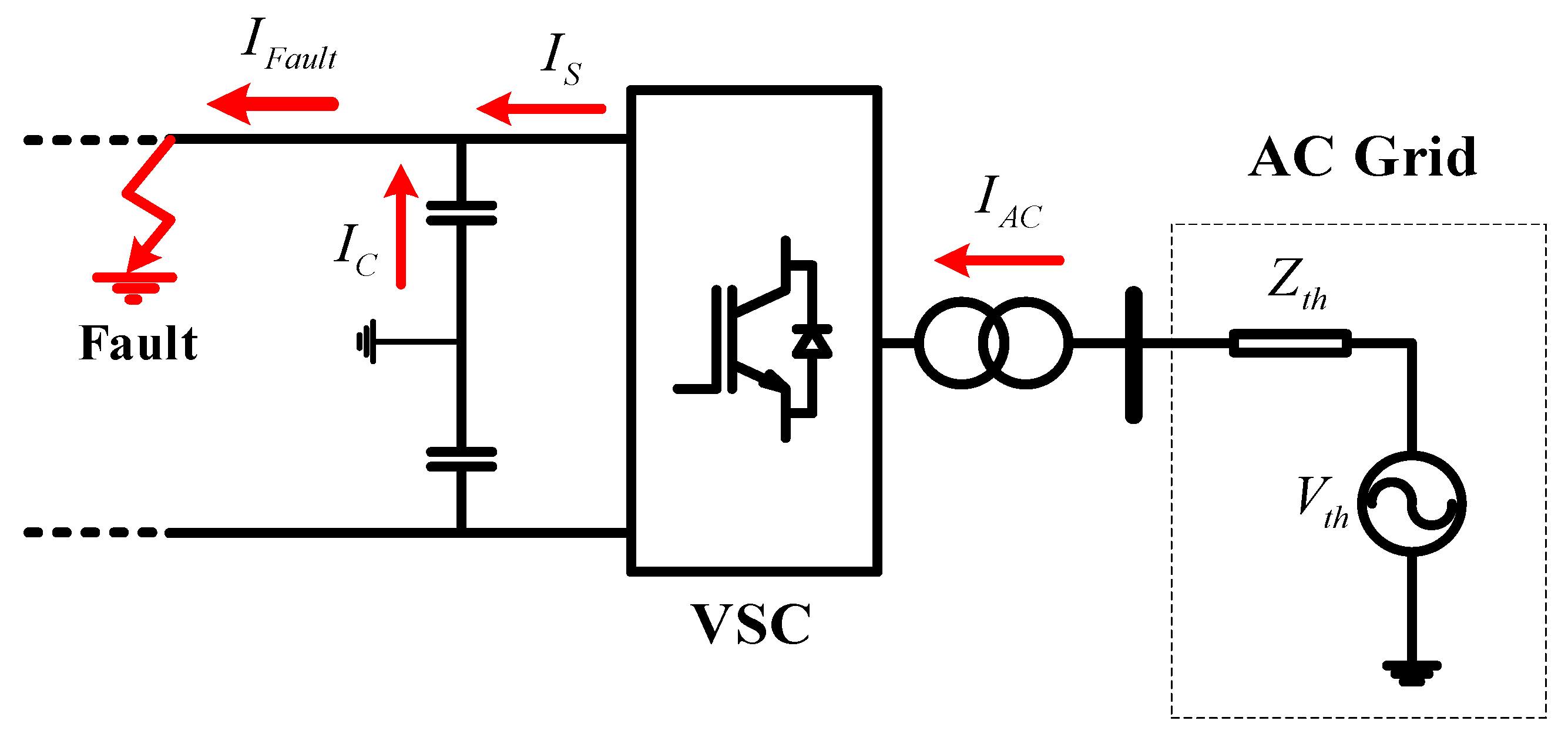
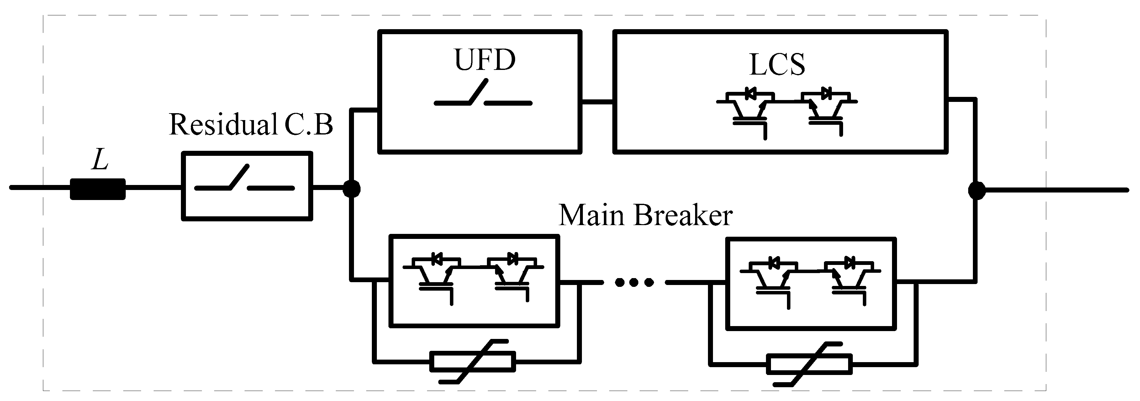
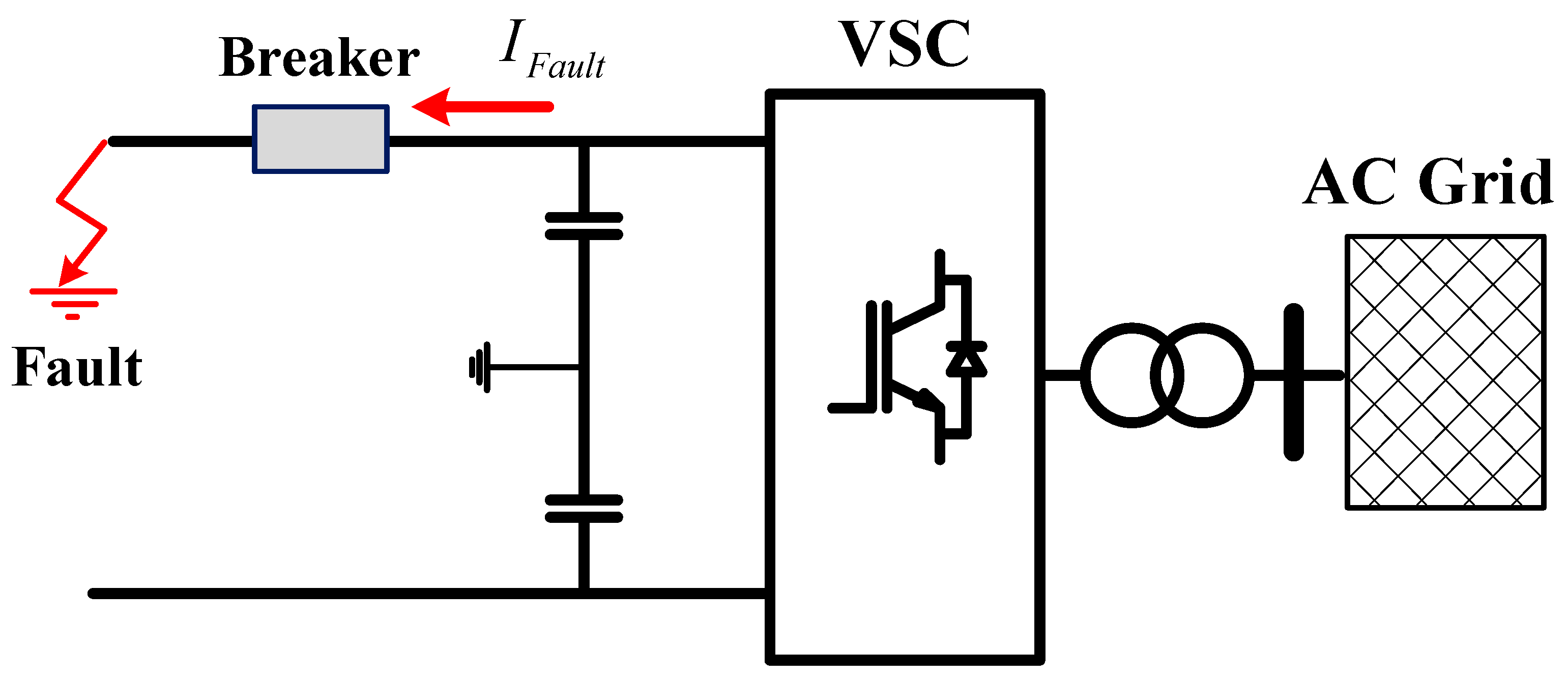
2. DC Fault Challenges and HVDC Hybrid Breaker Operation

The HVDC fault current is fed by the discharging current of the DC line capacitor and the injected current of the voltage source converter (VSC) that is provided by the AC side. Considering the low impedance of the DC line and the high provided fault current by the DC system, a fault occurrence can damage the solid-state devices. This situation is illustrated in Figure 1 where the fault occurred in the positive terminal of the DC line.
To protect the HVDC system against a fault current, a hybrid breaker is implemented in the DC line. A structure of this type of breaker is depicted in Figure 2. This topology consists of an inductive limiter that is connected in a series with the residual mechanical breaker. Moreover, there are two parallel branches. One is the load commutation switch (LCS) IGBT branch and its series ultrafast disconnector (UFD). The second branch is comprised of series diodes, IGBTs and parallel arresters. The features data of the hybrid breaker parts and DC system parameters are listed and described in Table 1. Its operation in the fault occurrence is as follows: when a fault detection signal is received by the breaker as a trip comment, the LCS opens and the current will be commutated to the main breaker while in the normal operation state this switch conducts the line current by imposing a very low impedance to the DC line. Until the UFD isolates the LCS from the DC system voltage in the fault state, the current will pass through the main breaker. Immediately thereafter, the main breaker switches off the fault current and dissipated energy is damped by the conducted current of the arresters throughout the damping time constant. In terms of the main breaker operation, this switch contacts the current throughout approximately 1 m/s in the fault occurrence state. The structure of the main breaker consists of packed 4.5 kV IGBTs and series diodes that are connected in series. The voltage of each packed switch is 3.65 V [30]. Considering a 200 kV direct voltage, this breaker must tolerate almost 400 kV as the peak of the recovery voltage. Consequently, 89 series IGBTs and 89 series diodes must be prepared to tolerate the voltage level. Moreover, considering the fault current curve, the main breaker power loss can be calculated as presented in Equation (7).

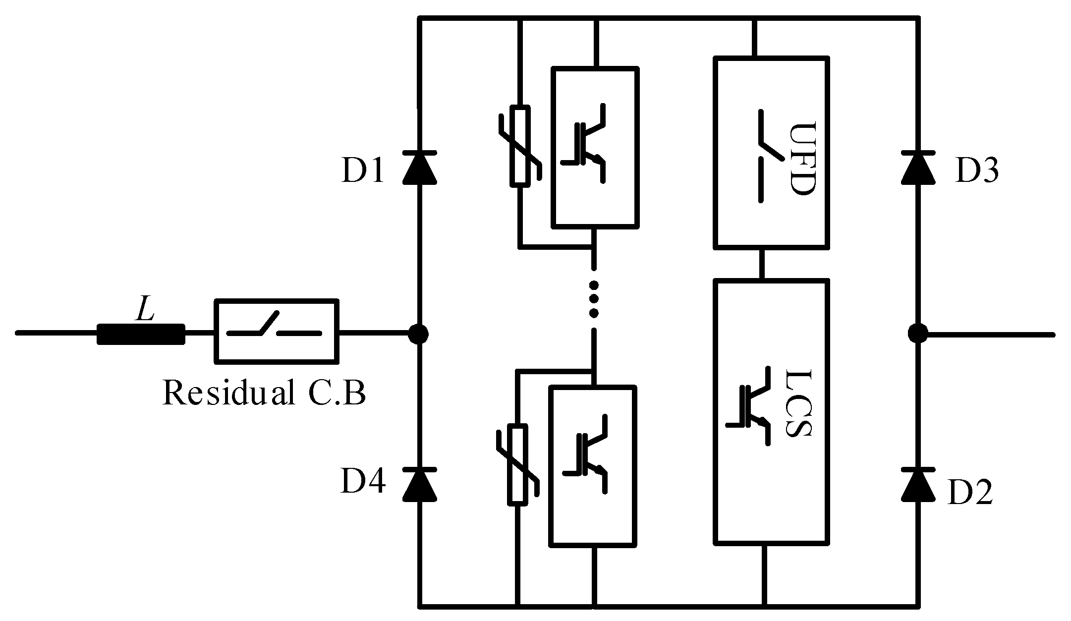
3. The Concept of the BHB

In this section, the concept of the BHB is discussed. This topology consists of a high current low voltage full-bridge that works as a bidirectional switch, the unidirectional main breaker, unidirectional LCS switch, UFD and arrester. The proposed BHB is depicted in Figure 3.
In this topology, the main breaker and the LCS are unidirectional switches. It means that there are no diodes in these switches and the number of the semiconductor switches becomes half. For instance, D1, D2 and the LCS are a contacted line current in a forward direction; besides D3, D4 and the LCS the backward line current is contacted. Therefore, the main breaker can break a fault current in both current directions. In the forward direct fault instance, first of all the LCS including a high current low voltage IGBT switch is turned off and it commutates the current to the main breaker switch. The fault current is then conducted through the main breaker. Thereafter, the UFD commences to isolate the LCS from the DC system voltage and breaking process voltage stress. After opening the UFD, the main breaker opens the faulty line and ultimately the stored energy in the DC system is damped by the operation of an arrester. An arrester as a nonlinear voltage depended resistor comprises of a series of units. By increasing the voltage in the main breaker terminals, the arrester starts to conduct the current and its operation is finished by suppressing voltage stress. By considering the proper operation of the BHB, the leakage current is passed through the equipment of the BHB, which can cause a high power loss. Thus, the residual switch opens the faulty line in the final stage to impose a high isolation to the HVDC line. According to the above-mentioned operational process of the BHB, the fault current is interrupted using less amounts of semiconductor rather than the hybrid HVDC breaker.

4. Power Loss Study of the BHB and the Hybrid Breaker

In this section, the operation of both the BHB and the hybrid breaker was simulated and then its power loss was analytically studied to clarify the performance enhancement of the proposed BHB. HVDC line parameters were included as shown in Table 1 while the considered diagram for simulation was configured as in Figure 4. The model detail was selected from a point-to-point HVDC line of the CIGRE B4-58 MT HVDC test system. In Figure 4 it is illustrated that the fault occurred in the positive terminal of the DC line whereas the fault current was provided by the capacitor and send ending of the VSC. On the other hand, the studied DC breakers were connected to the faulty line.

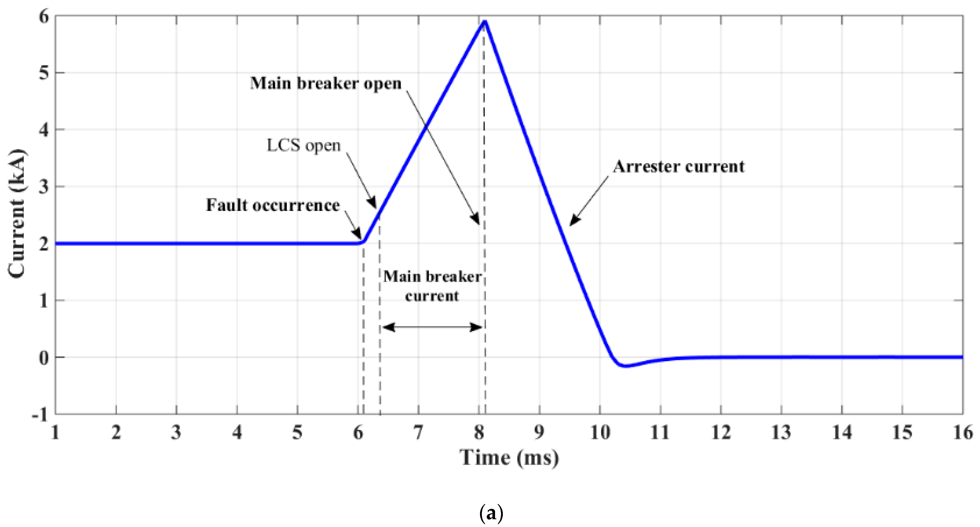
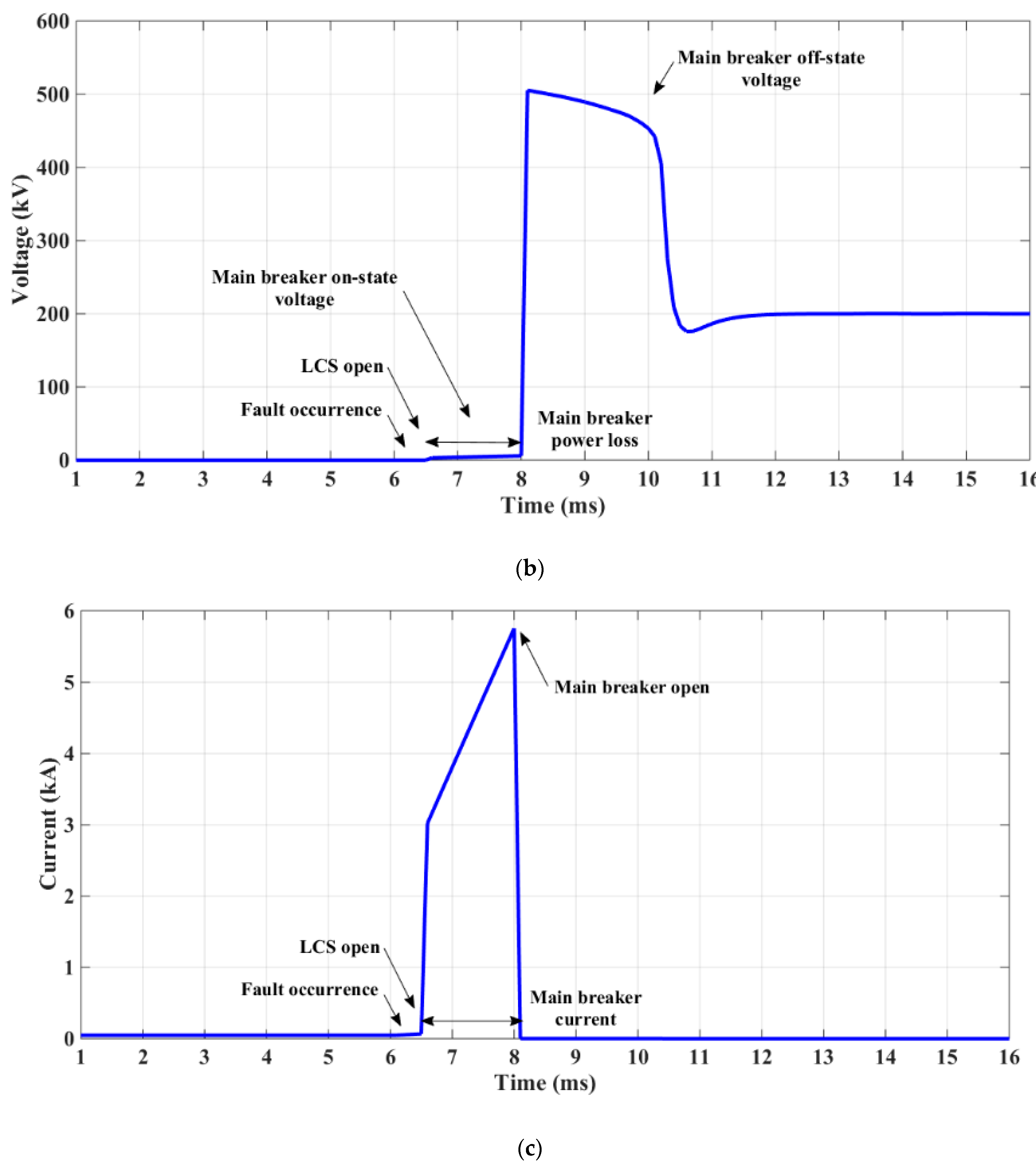
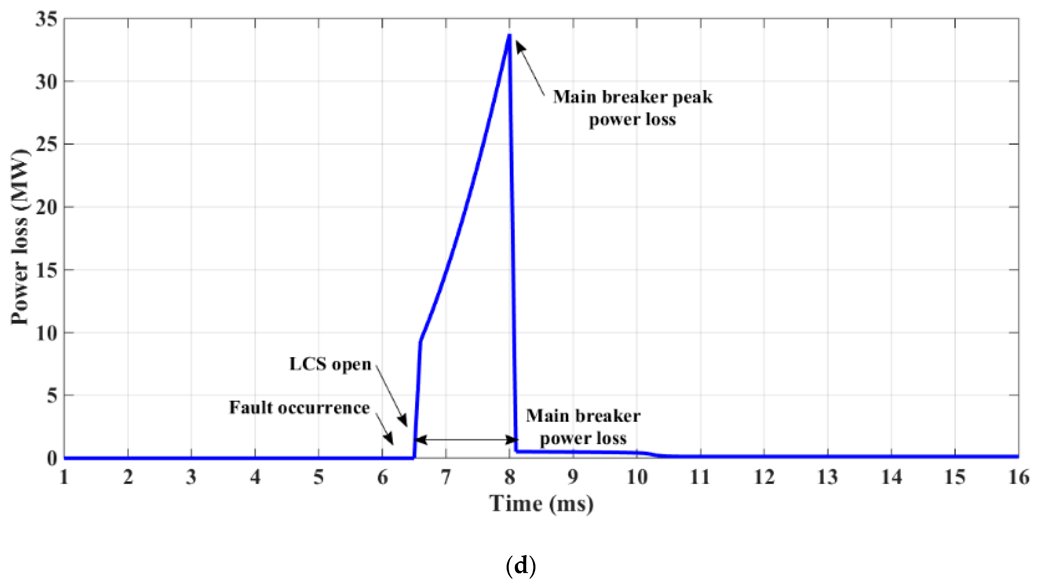
4.1. Hybrid Breaker Operation Analysis

In this case, a fault occurred between the positive terminal and the ground at t1 = 6.1 m/s whereas the line was protected by a hybrid breaker. After a short delay, the LCS was turned off at t2 = 6.4 m/s to commutate the current to the main breaker. The line fault current was passed by the main breaker from t2 to t3 = 8.1 m/s and then by operating the UFD, the main breaker operation was opened and the current passed through an arrester to damp the stored energy in the system. The line current equation in the three above-mentioned states is given in Equations (1)–(3). Its simulated line current signal is demonstrated in Figure 5a, which experienced almost 5.8 kA as its maximum value.
i ( t ) = V d c ( R e q + R l c s ) ( 1 e ( R e q   +   R l c s L e q   +   L s r ) )   t 0 t < t 1
where Req was the equivalent resistance of the DC system and Rlcs was the resistance of the LCS. Additionally, Leq was the equivalent inductance of DC system and Lsr was the inductance of the limiter series reactor. Vdc was the voltage of the DC system and i(t) was the DC line current. In Equation (2), the resistance of the conducted pass was increased by Rmb as the resistance of the main breaker.
i ( t ) = V d c ( R e q   +   R m b ) ( 1 e ( R e q   +   R m b L e q   +   L s r ) )   t 1 t < t 2 .
By operating the main breaker to an open status, the current passed through a nonlinear resistor as the arrester. The behavior of the arrester depended on its structure. The signal of the main breaker current is given in Figure 5c and its maximum value reached 5.7 kA. Equation (3) describes the line current in the third part of the hybrid breaker function.
  i ( t ) = v ( t ) R ( V ) = v ( t ) R f   +   e α v ( t )   t 2 t < t 3 .
Here, v(t) was the voltage of the breaker and R(V) was the voltage-dependent resistor of the arrester. Rf was the constant resistor of the arrester, α was a coefficient of the arrester and e-α defined the nonlinear behavior of the arrester.
In the terms of the voltage signal of the hybrid breaker, the voltage drop in the first section of the breaker operation was close to zero because of the very low impedance of LCS as shown in Figure 4. In Equation (4), Rlcs was the resistance of the switch, iline was the line current, Vlcs was the forward voltage drop of the IGBTs and Vd was the forward voltage drop of the diodes, respectively. In the second phase of the breaker operation, the voltage drop appeared on the main breaker as shown in Equation (5) and in the last section, the voltage drop of the breaker consisted of voltage stress and line voltage depending on the arrester behavior as shown in Equation (6). The voltage signal is reported in Figure 5b. As a simulation result, its maximum exceeded 500 kV.
v ( t ) = R l c s i l i n e + V l c s + V d   t 0 t < t 1 .
v ( t ) = R m b V d c ( R e q + R m b ) ( 1 e ( R e q + R m b L e q + L s r ) ) + n ( V f s + V f d )   t 1 t < t 2 .
v ( t ) = R e q v ( t ) ( R f + e α v ( t ) ) + ( L e q + L s r ) d ( R e q v ( t ) ( R f + e α v ( t ) ) ) / d t   t 2 t < t 3 .
In Equation (5), n was the number of solid-state elements, Vfs was a forward voltage drop of the IGBT and Vfd was a forward voltage drop of the diodes, respectively. Figure 5c demonstrates only the current of the main breaker, which considered its voltage drop as a result from its power loss during its close state as shown in Figure 5d. The peak value of power loss in the hybrid breaker reached close to 34 MW. The following Equation presents the main breaker power loss.
p l o s s ( t ) = R m b ( V d c ( R e q + R m b ) ( 1 e ( R e q + R m b L e q + L s r ) ) ) 2 + n ( V f s + V f d ) ( V d c ( R e q + R m b ) ( 1 e ( R e q + R m b L e q + L s r ) ) ) .

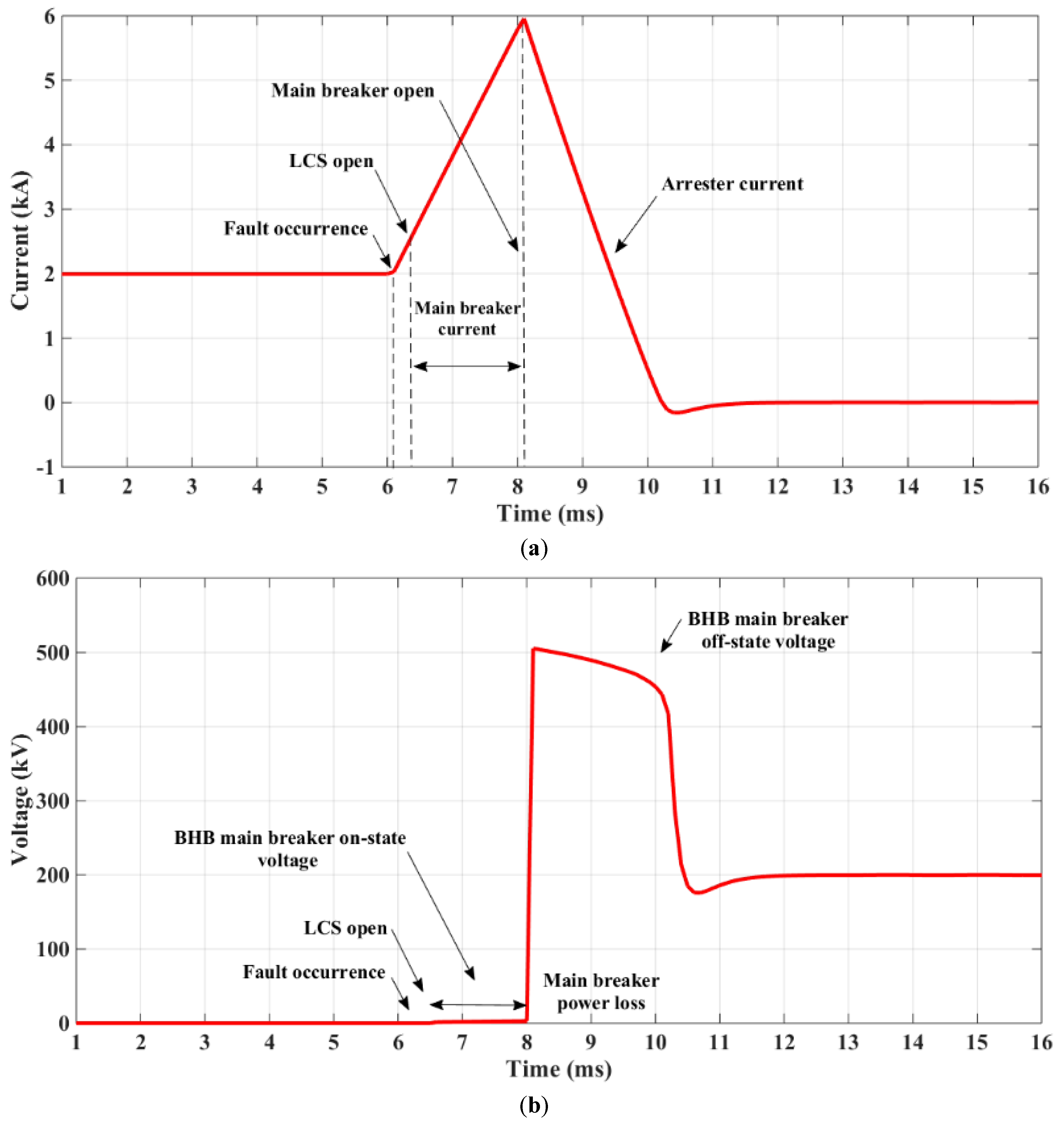
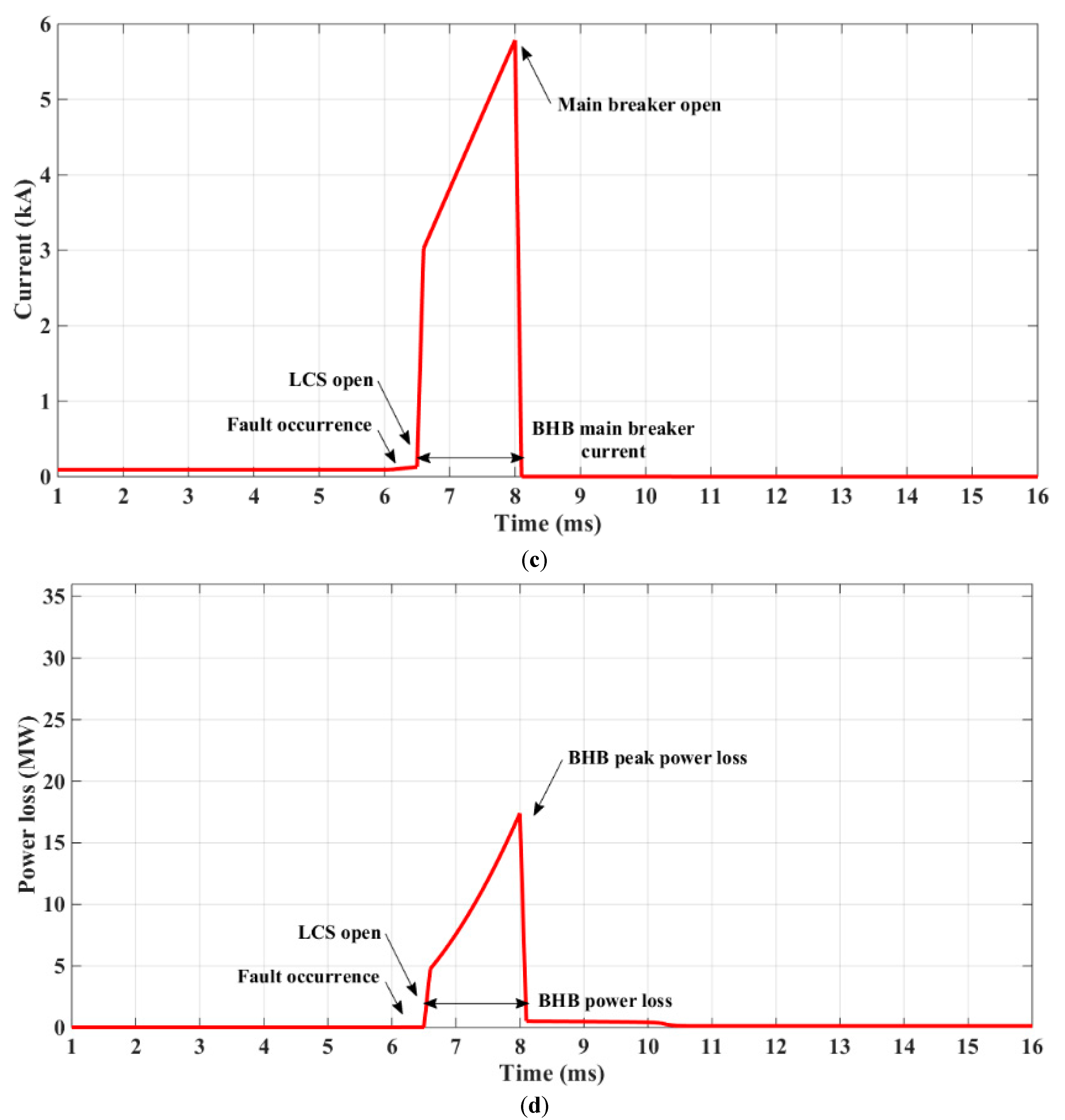
4.2. BHB Operation Analysis

In the first and third phase of the DC breaker operation, the BHB operated the same as the hybrid breaker. The only difference that enhanced the BHB operation was related to the second phase of the operation when the current was conducted by the main breaker. In this part, it was clear that the resistance of the main breaker and its forward voltage drop was considerably reduced. Accordingly, the current of the BHB main breaker, its voltage drop and power loss was calculated as follows:
i ( t ) = V d c ( R e q + R b h b ) ( 1 e ( R e q + R b h b L e q + L s r ) )   t 1 t < t 2 .
v ( t ) = R b h b V d c ( R e q + R b h b ) ( 1 e ( R e q + R b h b L e q + L s r ) ) + n ( V f s )   t 1 t < t 2 .
p l o s s ( t ) = R b h b ( V D C ( R e q + R b h b ) ( 1 e ( R e q + R b h b L e q + L s r ) ) ) 2 + n ( V f s ) ( V d c ( R e q + R b h b ) ( 1 e ( R e q + R b h b L e q + L s r ) ) ) .
Here, Rbhb was the resistance of the BHB main breaker that was less than Rmb. It was shown that the power loss in Equation 10 was drastically decreased because of the elimination of the diode’s voltage drop. In Figure 6, the line current, BHB voltage drop, main breaker current and main breaker power loss are depicted. In Figure 6a it is shown that the peak of the line current experienced a very small increase from 5.8 kA to 5.9 kA because of the BHB voltage drop decreasing. As a result of BHB benefits, the voltage drop of the main breaker was considerably reduced as shown in Figure 6b. This voltage was reduced from 387 V to 324 V. In Figure 6c, the current of the main breaker is depicted once the LCS commutated the current to the main breaker and its peak reached almost 5.9 kA. The power loss of the main breaker decreased from almost 34 MW to approximately 17 MW as shown in Figure 6d.

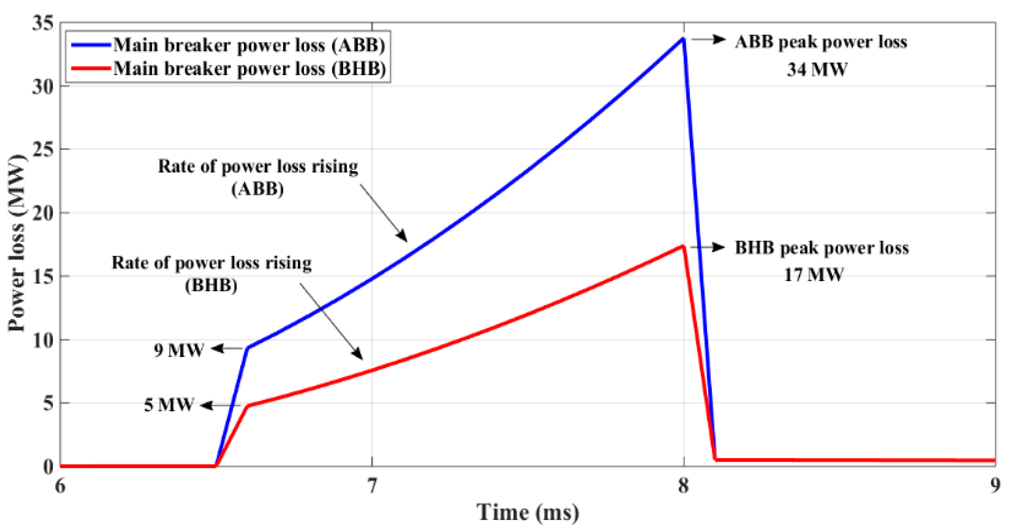
5. Comparison of the BHB and the Hybrid Breaker

In this section, a comparison of the hybrid breaker and the proposed BHB is reported. In the BHB, the LCS consisted of a series of unidirectional IGBTs but did not have anti-parallel diodes. Additionally, the main breaker of the BHB consisted only of unidirectional IGBTs whereas no diodes were used. Thus, the forward voltage drop of the main breaker and its equivalent resistance was substantially lower than the hybrid breaker. The power loss of the main breaker of the BHB was entirely less than the hybrid breakers. To show the comparison of the BHB and the hybrid breaker Table 2 is given. Here, the nominal voltage of the DC system was considered to be 200 kV, 2 kA.
As shown in Table 2, the main breaker forward voltage drop decreased up to 16% and the LCS forward voltage became half. In addition, the number of anti-parallel diodes in the BHB reached zero. To sum up, the power loss of the main breaker as shown in Table 2 was substantially decreased (near to the half of the power loss in the hybrid breaker). To depict this enhancement, Figure 7 compares the power loss of both breakers together.
As shown in Figure 7, the power loss of the main breakers reached the first peak after 0.1 m/s and then its rate considerably decreased. Thereafter, the main breakers experienced their maximum power loss in t = 8 m/s. In Figure 7, it is clearly shown that not only was the magnitude of power loss in the BHB significantly lower than the hybrid breaker, which was a decrease of up to 50%, but also the rate of power loss was considerably decreased from almost 16,700 in the DC hybrid breaker to 7900 in the BHB.

6. Conclusions

In this paper, a new topology named bridge-type hybrid breaker (BHB) was developed and studied for the purpose of the hybrid HVDC breaker power loss reduction throughout its operation. By utilizing a diode full-bridge, the developed unidirectional hybrid breaker became a bidirectional breaker. As has been shown, there was no need to install anti-parallel diodes compared with the hybrid HVDC breaker. In the developed breaker, the forward voltage of the main breaker and its resistance was substantially decreased while the number of solid-state switches was reduced. Consequently, by developing this type of DC circuit breaker, the power loss of the DC circuit breaker was properly reduced, which directly depended on a considerable decrease of the number of series semiconductor switches.

Author Contributions

Main contributor and preparing the first draft, M.H., A.B.; Resources, anaysis and figure preparing, S.M.; Mathematical analysis and verifications K.R. and J.M.E. All authors have read and agreed to the published version of the manuscript.

Funding

This research received no external funding.

Institutional Review Board Statement

Not applicable.

Conflicts of Interest

The authors declare no conflict of interest.

References

  1. Rodriguez, P.; Rouzbehi, K. Multi-terminal DC grids: Challenges and prospects. J. Mod. Power Syst. Clean Energy 2017, 5, 515–523. [Google Scholar] [CrossRef] [Green Version]
  2. Rouzbehi, K.; Candela, J.I.; Gharehpetian, G.B.; Harnefors, L.; Luna, A.; Rodriguez, P. Multiterminal DC grids: Operating analogies to AC power systems. Renew. Sustain. Energy Rev. 2017, 70, 886–895. [Google Scholar] [CrossRef]
  3. Franck, C.M. HVDC Circuit Breakers: A Review Identifying Future Research Needs. IEEE Trans. Power Deliv. 2011, 26, 998–1007. [Google Scholar] [CrossRef] [Green Version]
  4. Mokhberdoran, A.; Carvalho, A.; Leite, H.; Silva, N. A review on HVDC circuit breakers. In Proceedings of the 3rd Renewable Power Generation Conference (RPG 2014), Naples, Italy, 24–25 September 2014; pp. 1–6. [Google Scholar]
  5. Kinjo, R.; Ohta, R.; Matayosh, H.; Senjyu, T.; Howlader, A.M. Resonant DC circuit breaker in MMC-HVDC transmission system. In Proceedings of the 2017 IEEE 12th International Conference on Power Electronics and Drive Systems (PEDS), Honolulu, HI, USA, 12–15 December 2017; pp. 71–74. [Google Scholar]
  6. Thomas, J.; Chaffey, G.P.; Franck, C.M. Small-Scale HVDC Circuit Breaker. IEEE Trans. Compon. Packag. Manuf. Technol. 2017, 7, 1058–1068. [Google Scholar] [CrossRef]
  7. Sano, K.; Takasaki, M. A Surgeless Solid-State DC Circuit Breaker for Voltage-Source-Converter-Based HVDC Systems. IEEE Trans. Ind. Appl. 2014, 50, 2690–2699. [Google Scholar] [CrossRef] [Green Version]
  8. Li, C.; Liang, J.; Wang, S. Interlink Hybrid DC Circuit Breaker. IEEE Trans. Ind. Electron. 2018, 65, 8677–8686. [Google Scholar] [CrossRef]
  9. Grieshaber, W.; Dupraz, J.; Penache, D.; Violleau, L. Development and Test of A 120 kV Direct Current Circuit Breaker. In CIGRÉ Session; Paper B4-301; CIGRÉ: Paris, France, 24 August 2014. [Google Scholar]
  10. Hassanpoor, A.; Häfner, J.; Jacobson, B. Technical Assessment of Load Commutation Switch in Hybrid HVDC Breaker. IEEE Trans. Power Electron. 2015, 30, 5393–5400. [Google Scholar] [CrossRef]
  11. Kontos, E.; Schultz, T.; Mackay, L.; Ramirez-Elizondo, L.M.; Franck, C.M.; Bauer, P. Multiline Breaker for HVdc Applications. IEEE Trans. Power Deliv. 2018, 33, 1469–1478. [Google Scholar] [CrossRef]
  12. Heidary, A.; Bigdeli, M.; Rouzbehi, K. Controllable reactor based hybrid HVDC breaker. High Volt. 2020, 5, 543–548. [Google Scholar] [CrossRef]
  13. Jovcic, D. Series LC DC circuit breaker. High Volt. 2019, 4, 130–137. [Google Scholar] [CrossRef]
  14. Heidary, A.; Rouzbehi, K.; Hesami, M.; Bigdeli, M.; Bordons, C. Bridge-type fault current limiter and hybrid breaker for HVDC grids applications. IET Gener. Transm. Distrib. 2020, 14, 3913–3919. [Google Scholar] [CrossRef]
  15. Sima, W.; Fu, Z.; Yang, M.; Yuan, T.; Sun, P.; Han, X.; Si, Y. A Novel Active Mechanical HVDC Breaker with Consecutive Interruption Capability for Fault Clearances in MMC-HVDC Systems. IEEE Trans. Ind. Electron. 2019, 66, 6979–6989. [Google Scholar] [CrossRef]
  16. Yang, Q.; Blond, S.L.; Liang, F.; Yuan, W.; Zhang, M.; Li, J. Design and Application of Superconducting Fault Current Limiter in a Multiterminal HVDC System. IEEE Trans. Appl. Supercond. 2017, 27, 1–5. [Google Scholar] [CrossRef] [Green Version]
  17. Noe, M.; Steurer, M. High-temperature superconductor fault current limiters: Concepts, applications, and development status. Supercond. Sci. Technol. 2007, 20, R15–R29. [Google Scholar] [CrossRef]
  18. Khan, U.A.; Lee, J.; Amir, F.; Lee, B. A Novel Model of HVDC Hybrid-Type Superconducting Circuit Breaker and Its Performance Analysis for Limiting and Breaking DC Fault Currents. IEEE Trans. Appl. Supercond. 2015, 25, 1–9. [Google Scholar] [CrossRef]
  19. Heidary, A.; Radmanesh, H.; Rouzbehi, K.; Pou, J. A DC-Reactor-Based Solid-State Fault Current Limiter for HVdc Applications. IEEE Trans. Power Deliv. 2019, 34, 720–728. [Google Scholar] [CrossRef]
  20. Heidary, A.; Radmanesh, H.; Fathi, H.; Gharehpetian, G.B. Series transformer based diode-bridge-type solid state fault current limiter. Front. Inf. Technol. Electron. Eng. 2015, 16, 769–784. [Google Scholar] [CrossRef]
  21. Heidary, A.; Radmanesh, H.; Rouzbehi, K.; Moradi, H.; CheshmehBeig, H.M. A Multifunction High-Temperature Superconductive Power Flow Controller and Fault Current Limiter. IEEE Trans. Appl. Supercond. 2020, 30, 1–8. [Google Scholar] [CrossRef]
  22. Heidary, A.; Radmanesh, H.; Rouzbehi, K.; Mehrizi-Sani, A.; Gharehpetian, G.B. Inductive fault current limiters: A review. In Electric Power Systems Research; Elsevier: Amsterdam, The Netherlands, 2020; Volume 187, p. 106499. [Google Scholar]
  23. Heidary, A.; Radmanesh, H.; Moghim, A.; Ghorbanyan, K.; Rouzbehi, K.; MG Rodrigues, E.M.; Pouresmaeil, E. A Multi-Inductor H Bridge Fault Current Limiter. Electronics 2019, 8, 795. [Google Scholar] [CrossRef] [Green Version]
  24. Radmanesh, H.; Heidary, A.; Fathi, S.H.; Gharehpetian, G.B. Dual function ferroresonance and fault current limiter based on DC reactor. IET Gener. Transm. Distrib. 2016, 10, 2058–2065. [Google Scholar] [CrossRef]
  25. Heidary, A.; Radmanesh, H.; Naghibi, S.H.; Samandarpour, S.; Rouzbehi, K.; Shariati, N. Distribution system protection by coordinated fault current limiters. IET Energy Syst. Integr. 2020, 2, 59–65. [Google Scholar] [CrossRef]
  26. Radmanesh, H.; Fathi, S.H.; Gharehpetian, G.B.; Heidary, A. A Novel Solid-State Fault Current-Limiting Circuit Breaker for Medium-Voltage Network Applications. IEEE Trans. Power Deliv. 2016, 31, 236–244. [Google Scholar] [CrossRef]
  27. Heidary, A.; Radmanesh, H.; Bakhshi, A.; Rouzbehi, K.; Pouresmaei, E. A Compound Current Limiter and Circuit Breaker. Electronics 2019, 8, 551. [Google Scholar] [CrossRef] [Green Version]
  28. Callavik, M.; Blomberg, A.; Hafner, J.; Jacobson, B. The Hybrid HVDC Breaker—An Innovation Breakthrough Enabling Reliable HVDC Grids. ABB Grid Syst. Tech. Paper 2012, 361, 143–152. [Google Scholar]
  29. Heidary, A.; Radmanesh, H.; Fathi, S.H.; Khamse, H.R. Improving transient recovery voltage of circuit breaker using fault current limiter. Res. J. Appl. Sci. Eng. Technol. 2012, 4, 5123–5128. [Google Scholar]
  30. Eicher, S.; Rahimo, M.; Tsyplakov, E.; Schneider, D.; Kopta, A.; Schlapbach, U.; Carroll, E. 4.5 kV press pack IGBT designed for ruggedness and reliability. In Proceedings of the Conference Record of the 2004 IEEE Industry Applications Conference, Seattle, WA, USA, 3–7 October 2004; Volume 3, pp. 1534–1539. [Google Scholar]
  31. Liu, L.; Yuan, Z.; Xu, H.; Chen, L.; He, J.; Pan, Y.; Cen, Y. Design and Test of A new kind of Coupling Mechanical HVDC circuit breaker. Inst. Eng. Technol. Gen. Transm. Dist. 2019, 11, 1751–8687. [Google Scholar] [CrossRef]
  32. Wen, W.; Huang, Y.; Li, B.; Wang, Y.; Cheng, T. Technical Assessment of Hybrid DCCB with Improved Current Commutation Drive Circuit. IEEE Trans. Ind. Appl. 2018, 54, 5456–5464. [Google Scholar] [CrossRef]
  33. Pang, H.; Wei, X. Research on key technology and equipment for Zhangbei 500kV DC grid. In Proceedings of the 2018 International Power Electronics Conference (IPEC-Niigata 2018-ECCE Asia), Niigata, Japan, 20–24 May 2018. [Google Scholar]
Figure 1. Fault occurrence in the high voltage direct current (HVDC) line.
Energies 14 01526 g001
Figure 2. Structure of the ABB HVDC hybrid breaker.
Energies 14 01526 g002
Figure 3. Proposed bridge configuration of the hybrid breaker.
Energies 14 01526 g003
Figure 4. Simulated diagram of a DC system and a DC breaker.
Energies 14 01526 g004
Figure 5. Simulated HVDC line and hybrid breaker. (a) The DC line current in the normal and fault condition. (b) The hybrid breaker voltage drop in operation mode. (c) The main breaker current (hybrid breaker). (d) The main breaker power loss (hybrid breaker).
Energies 14 01526 g005aEnergies 14 01526 g005bEnergies 14 01526 g005c
Figure 6. Simulated HVDC line and bridge structure of a hybrid breaker (BHB). (a) Line current in normal and fault conditions. (b) BHB voltage drop in operation mode. (c) Main breaker current (BHB). (d) Main breaker power loss (BHB).
Energies 14 01526 g006aEnergies 14 01526 g006b
Figure 7. Comparison of the BHB and hybrid breaker power loss.
Energies 14 01526 g007
Table 1. Hybrid breaker components and direct current (DC) system parameters.
ComponentsDescriptionValue
LCSLow voltage high current IGBT switch2 kA, 5 kV
UFDMechanical HV ultrafast disconnector400 kV, 2 m/s
Main breakerSeries IGBT and anti-parallel diodes2 kA, 400 kV
ArresterVoltage-dependent resistor for dissipation energy damping4 MJ
Limiter inductorSeries reactor as a current limiter100 mH
VlinePositive or negative pole voltage200 kV
IlineThe DC line maximum current2 kA
LlineThe DC line inductance50 mH
RlineThe DC line resistance0.5 Ω
ClineThe DC line modeled capacitor0.6 uf
CSThe DC line Smoothing capacitor80 mF
RfaultFault resistance0.01 Ω
Table 2. Comparison of the BHB and the hybrid breaker.
Compared FactorsBHBHybrid Breaker
Number of LCS IGBTs10 IGBT switches10 IGBT switches
Number of LCS diodes0 10
Number of main breaker IGBTs89 IGBT switches89 IGBT switches
Main breaker forward voltage drop324 V387 V
LCS forward voltage drop0.9 V1.78 V
Number of main breaker diodes0 89
Number of full-bridge diodes4 0
Main breaker peak power loss during fault current17 MW34 MW
Publisher’s Note: MDPI stays neutral with regard to jurisdictional claims in published maps and institutional affiliations.

