Article

A Comparison of Partial Admission Axial and Radial Inflow Turbines for Underwater Vehicles

1
School of Marine Science and Technology, Northwestern Polytechnical University, Xi’an 710072, Shaanxi, China
2
Xi’an Precision Machinery Research Institute, Xi’an 710077, Shaanxi, China
*
Author to whom correspondence should be addressed.
Energies 2021, 14(5), 1514; https://doi.org/10.3390/en14051514
Submission received: 9 February 2021 / Revised: 24 February 2021 / Accepted: 5 March 2021 / Published: 9 March 2021

Abstract

:
The metal fueled steam Rankine cycle has been successfully applied to Unmanned Underwater Vehicles. However, the suitable turbine configuration is yet to be determined for this particular application. In this paper, the mean-line design approach based on the existing empirical correlations is first described. The corresponding partial admission axial and radial inflow turbines are then preliminarily designed. To assess the performance of designed turbines, the three-dimensional Computational Fluid Dynamics (CFD) simulations and steady-state structural analysis are performed. The results show that axial turbines are more compact than radial inflow turbines at the same output power. In addition, since radial inflow turbines can reduce the exit energy loss, this benefit substantially offsets the increment of the rotor losses created by the low speed ratios and supersonic rotor inlet velocity. On the contrary, due to the large volume of dead gas and strong transient effects caused by the high rotor blade length of radial inflow turbines, the overall performance between axial and radial inflow turbines is comparable (within 4%). However, the strength of radial inflow turbines is slightly superior because of lower blade inlet height and outlet hub radius. This paper confirms that the axial turbine is the optimal configuration for underwater vehicles in terms of size, aerodynamics and structural performance.

1. Introduction

Unmanned Underwater Vehicles (UUVs) are used in different applications, for example, oceanographic data measurements, bottom and bathymetric imaging, collecting intelligence, surveillance and reconnaissance, cable-laying and mine-detection [1]. Because of the relative low energy density of electrochemical energy, the operational range is limited by using primary and secondary batteries [2]. The Stored Chemical Energy Propulsion System (SCEPS) [3] was successfully applied to power UUVs due to the high energy density of the metal fuel (aluminum and lithium) [4]. The axial turbine is typically selected as the power conversion unit [5]. However, radial inflow turbines are also an alternative. The suitable turbine configuration needs to be reexamined for UUVs.
The United States first applied turbines to UUVs as the alternative of reciprocating engines [6]. Due to its simplicity, reliability, strength, and durability compared to reciprocating engines, a one-inch pitch diameter impulse turbine was developed by Pennsylvania State University to power UUVs [7]. The axial turbine characterized by a single-stage, partial admission and supersonic structure is desired because of the easy manufacture of impulse blades and low leakage losses. Partial admission axial turbines are also used in rocket engines for simplex turbopumps [8,9]. However, radial inflow turbines can also be employed because of low cost, small size, high efficiency, and simple manufacturing [10]. They are mainly used in small turbochargers to achieve significant power gain when working with internal combustion engines [11,12]. In recent years, the investigation of axial and radial inflow turbines with the partial admission configuration has mainly focused on ORC (Organic Rankine cycle) [13,14] and supercritical CO2 cycles [15,16].
The selection criteria of axial and radial inflow turbines are still unclear, especially using the partial admission configuration. Existing studies indicate that the performance of radial and axial turbines is similar when the optimal specific speed is satisfied [17,18]. Dunham and Panton [19] proposed that due to the high rotor exit absolute velocity, the total-to-static efficiency of axial turbines is lower than that of radial inflow turbines. Branchini et al. [20] presented that the axial turbine is more suitable for high power application (10 MW) by summarizing the data of the existing turbomachinery applied to ORCs. Daabo et al. [21] concluded that, for solar Brayton cycle applications, radial inflow turbines are better than axial turbines, especially at high pressure ratio. Bahamonde et al. [22] showed that the performance of radial inflow turbines is better than axial turbines and radial outflow turbines for Mini-ORC. Weißa et al. [23] showed that the efficiency of radial inflow turbines is significantly higher than axial turbines by summarizing the existing experimental data of small ORC turbines.
In the literature, radial inflow turbines seem to be more suitable for low-power and full-admission applications [20,21,22,23]. Besides, axial turbines usually use multi-stage for high pressure applications [20,21,22] and fewer studies for single stage [19,23], while radial turbines typically use single stage [19,20,21,22,23]. In addition, the existing studies for turbine comparisons are mainly established upon experimental results for full-admission radial inflow turbines [17,18,19,20,21,22,23]. The suitable turbine configuration under supersonic and partial admission conditions is still unclear. This paper aims to compare the performance of axial and radial inflow turbines for UUVs. The remainder of this paper is organized as follows. Section 2 and Section 3 introduce the radial and axial turbine mean-line and 3-D design method, followed by the introduction of the numerical model in Section 4. The comparisons of axial and radial inflow turbines are detailed in Section 5. The conclusions demonstrate the optimal micro-turbine selected for UUVs considering a low-power at low speed ratio working condition.

2. Radial Inflow Turbines

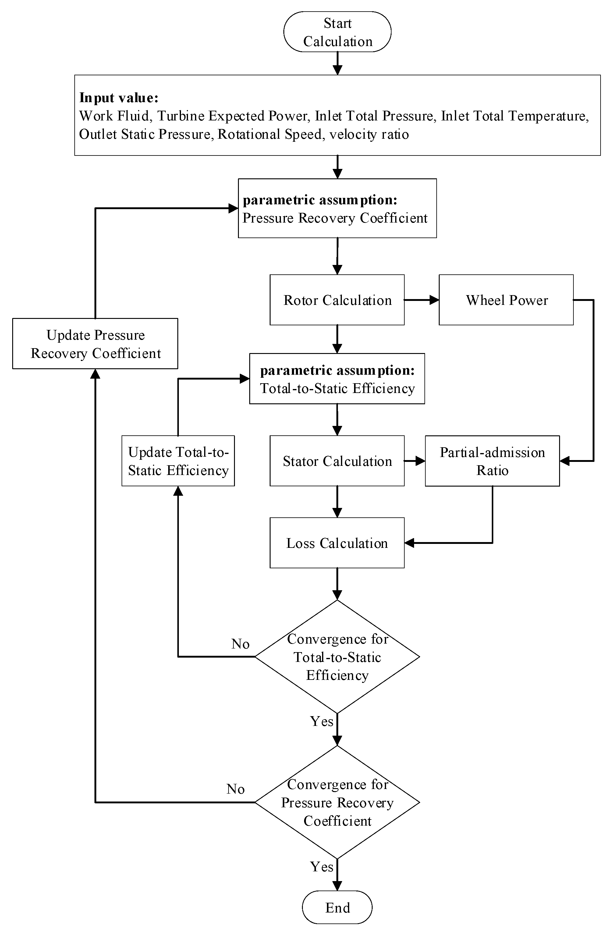
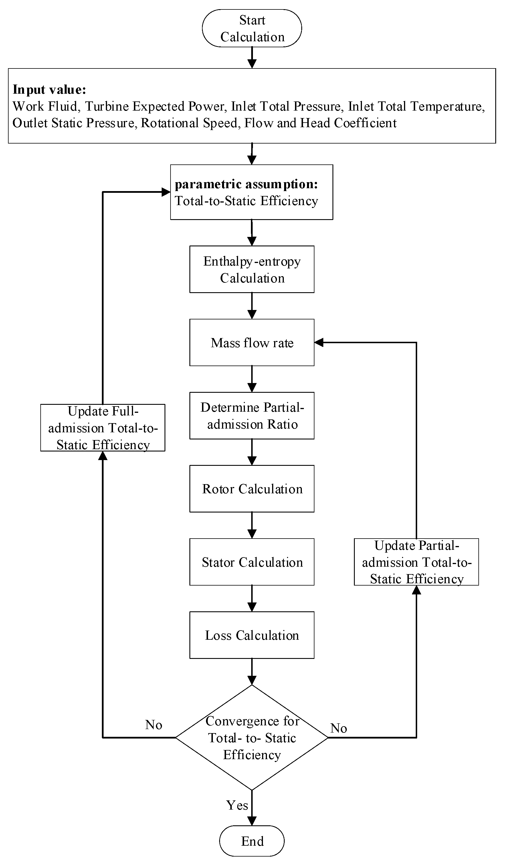
To choose the optimal point among many design parameters, this paper first uses the mean-line method to narrow the scope. The mean-line design method is derived from existing models [24]. The turbine input parameters (output power, rotational speed, inlet pressure and temperature, outlet pressure) are determined by the power system. For radial inflow turbines, the optimal design point is selected by the flow (ϕ) and head coefficients (ψ), as proposed by Whitfield and Baines [25]. The radial inflow turbine design process is shown in Figure 1. It is noted that the rotor outlet area is 0.4 times the full admission case to reduce partial admission losses when the partial admission ratio is less than 0.4. The performance prediction method is established upon the empirical correlations. The loss model considers the entropy increase due to secondary flow loss, viscosity loss, and mass flow loss [26]. Table A1 in Appendix A details the loss model used for radial inflow turbines [27,28,29,30,31,32,33,34,35]. The magnitude of the loss for radial inflow turbines is represented by the enthalpy drop, and the total-to-static efficiency is then calculated as:
η t s , f u l l = Δ h 0 Δ h 0 + Δ h l o s s , f u l l
η t s , p a r = Δ h 0 Δ h l o s s , p a r Δ h 0 + Δ h l o s s , f u l l
Some parameters, for instance, the total-to-static efficiency, must be assumed initially. The turbine is then preliminarily designed, and the assumed parameters are updated accordingly. The whole calculation process is iterated until the convergence is achieved. Typically, five iterations are required to obtain the converged solution when the relative error of the turbine efficiency between two consecutive steps is less than 1 × 10⁻³.
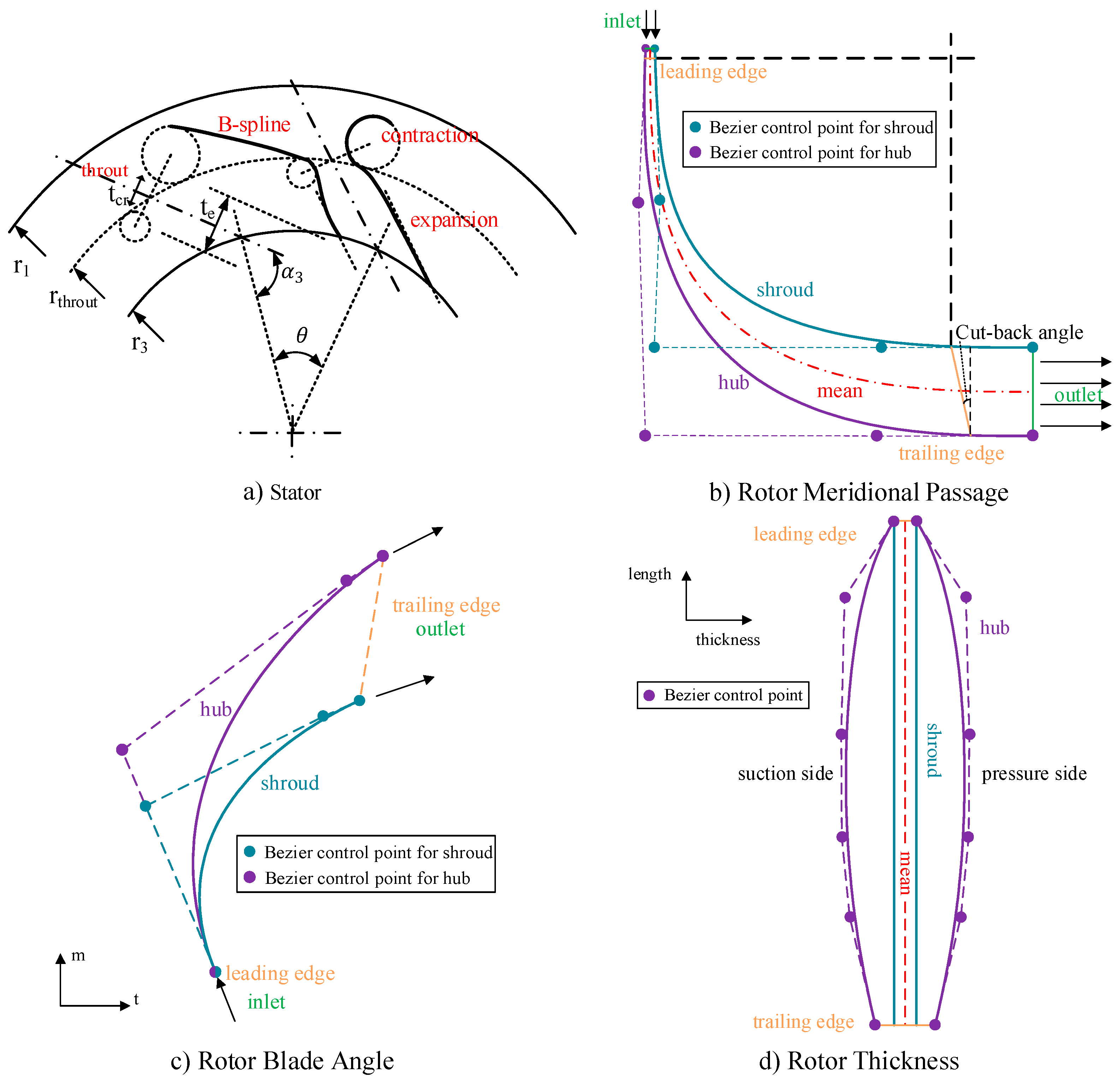
For the stator profile, it follows the design methods of Seo [36] and Anand [37]. As shown in Figure 2a, the contraction section and trailing edge are designed with circular arcs, and the divergent section follows the method of characteristics (MOC) based on the Prandtl–Meyer function. The transition employs a B-spline curve to reduce the loss caused by sudden area changes.
As shown in Figure 2b, the rotor shroud in the meridional-plane is assumed to be circular, while the hub is elliptical [38]. Referring to the design methodology from Wheeler [39], the rotor anterior segments should have a larger passage height than the usual design. Therefore, a more suitable transition (Bezier curves) for supersonic endwall lines is used [40]. In addition, the relative exit speed angle is assumed to be the same as the exit blade angle, and the blade curve from hub to tip is the line (see Figure 2c). For the inlet blade angle, the optimal incidence angle is calculated as proposed by Aungier [33]. The spatially curved meridional flow surfaces are mapped to a plane using coordinate transformation. This coordinate system has the angle in circumferential direction (t) and the dimensionless meridional extension (m). As shown in Figure 2c, the Bezier curve is used as the leading-to-trailing edge connection. For the blade thickness, the Bezier curve is also used from leading to trailing edge (see Figure 2d). The tip and hub thickness are initially selected as 0.5 mm, and the structural assessment is then performed. The hub thickness needs to be adjusted. Usually, the hub thicknesses are 1 to 5 times the tip thickness. To reduce the loss at the rotor inlet, the hub blade thickness at the rotor inlet is the same as the tip thickness. The maximum thickness is placed at the middle of the blade and gradually reduced to 1.5~2 mm at the trailing edge. In addition, to reduce the stress concentration caused by the centrifugal force at the trailing edge, the cut-back is used at the trailing edge, as shown in Figure 2b. The fillet is also added between the blade and hub.

3. Axial Turbines

For axial turbines, the velocity ratio ( χ = U m / C 0 ) is the key parameter to evaluate turbine performance [41]. The axial turbine design process is shown in Figure 3. Since the working fluid from the stator outlet decelerates and pressurizes in the rotor and outlet domain, it is necessary to assume the pressure recovery coefficient to calculate the actual pressure at the stator outlet. The pressure recovery coefficient kp is calculated as:
k p = ( 1 + ( B t 1 γ γ 1 ) ( 1 φ v 2 ) ) φ T φ m φ v = B t B a
The loss calculation method refers to Ohlsson [41], Linhardt [42], Zhang [43], and Li [44]. Different from the radial inflow turbines, the losses are represented by the equivalent loss factor, power drop and efficiency coefficient, as shown in Table A2 (Appendix A). The isentropic efficiency is then obtained:
η t s = P u η t i p P f r P w P exp m ˙ ( h 6 h 01 )
Similar to radial inflow turbines, five iterations are usually required to obtain the converged solution. The rotor geometry parameter is then determined by empirical parameters related to stator exit diameter.
The stator geometry adopts the traditional circular-type stator. As shown in Figure 4a, the convergent section profile uses a Witozinsky curve [45] based on the ideal incompressible symmetrical flow. The divergent section uses a typical straight line. The airfoil design adopts the traditional impulse airfoil, as shown in Figure 4b.

4. Numerical Model

Due to the lack of detailed experimental investigations on the partial admission configuration for this particular application, some empirical correlations might be inaccurate. The numerical method is then used to explore the suitability of empirical correlations. The three-dimensional CFD (Computational Fluid Dynamics) analysis is employed and the governing equation in ANSYS CFX can be expressed as [46]:
Continuity Equation
ρ t + ( ρ U ) = 0
Momentum Equations
( ρ U ) t + ( ρ U U ) = p + τ + S M
Total Energy Equation
( ρ h t o t ) t p t + ( ρ U h t o t ) = ( λ T ) + ( U τ ) + U S M + S E
The SST (Shear Stress Transfer) turbulence model can be expressed as follows:
( ρ k ) t + x j ( ρ U j k ) = x j [ ( μ + μ t σ k 3 ) k x j ] + P k β ρ k ω + P k b
( ρ ω ) t + x j ( ρ U j ω ) = x j [ ( μ + μ t σ ω 3 ) ω x j ] + ( 1 F 1 ) 2 ρ 1 σ ω 2 ω k x j ω x j + α 3 ω k P k β 3 ρ ω 2 + P ω b
The eddy-viscosity in SST model is limited, which is:
υ t = a 1 k max ( a 1 ω , S F 2 )
The second order numerical scheme is used to discretize advection and the first order is selected for turbulence numeric. All walls are modeled as non-slip and adiabatic. The calculation mesh must ensure that the y+ is in the scope between 10 and 100. The second order backward Euler scheme is used for time advancement. To improve the convergence, the steady state result is usually used as the initial results. The Courant number of 10 is then used for unsteady calculation. Moreover, the convergence criterion is based on the difference between two iterations of the total-to-static efficiency (less than 10–3), and the time-average value between two cycles is used for transient calculation. The total-to-static efficiency is defined as the ratio of the output power and available power (Equation (11)). The mass flow rate m ˙ and moment M can be directly recorded from the nozzle inlet and the rotor wall, respectively. In addition, the enthalpy drop Δ h i s is the ideal enthalpy difference between the turbine inlet and outlet, and the rotation speed ω is the input value. For transient results, the value is the time-averaged value in a single cycle.
η t s = P o u t p u t P a v a i l a b l e = M ω m ˙ Δ h i s
For the strength calculation, the static analysis governing equation is
( K ) { U } = { f }
The iterative solver with Preconditioned Conjugate Gradient (PCG) is used for steady-state structure analysis. The pressure from fluid calculation is remapped and transformed to the normal direction of the structure elements. The profile preserving transfer is applied to control the accuracy during data transfers. In addition, the bucket surface search algorithm is used to locate a source element that each target node can be mapped to. The triangulation method is set as the weighting type. In addition, the convergence tolerance is 10–8 and maximum iteration is defined by the DOF (degree of freedom) per node and number of nodes.
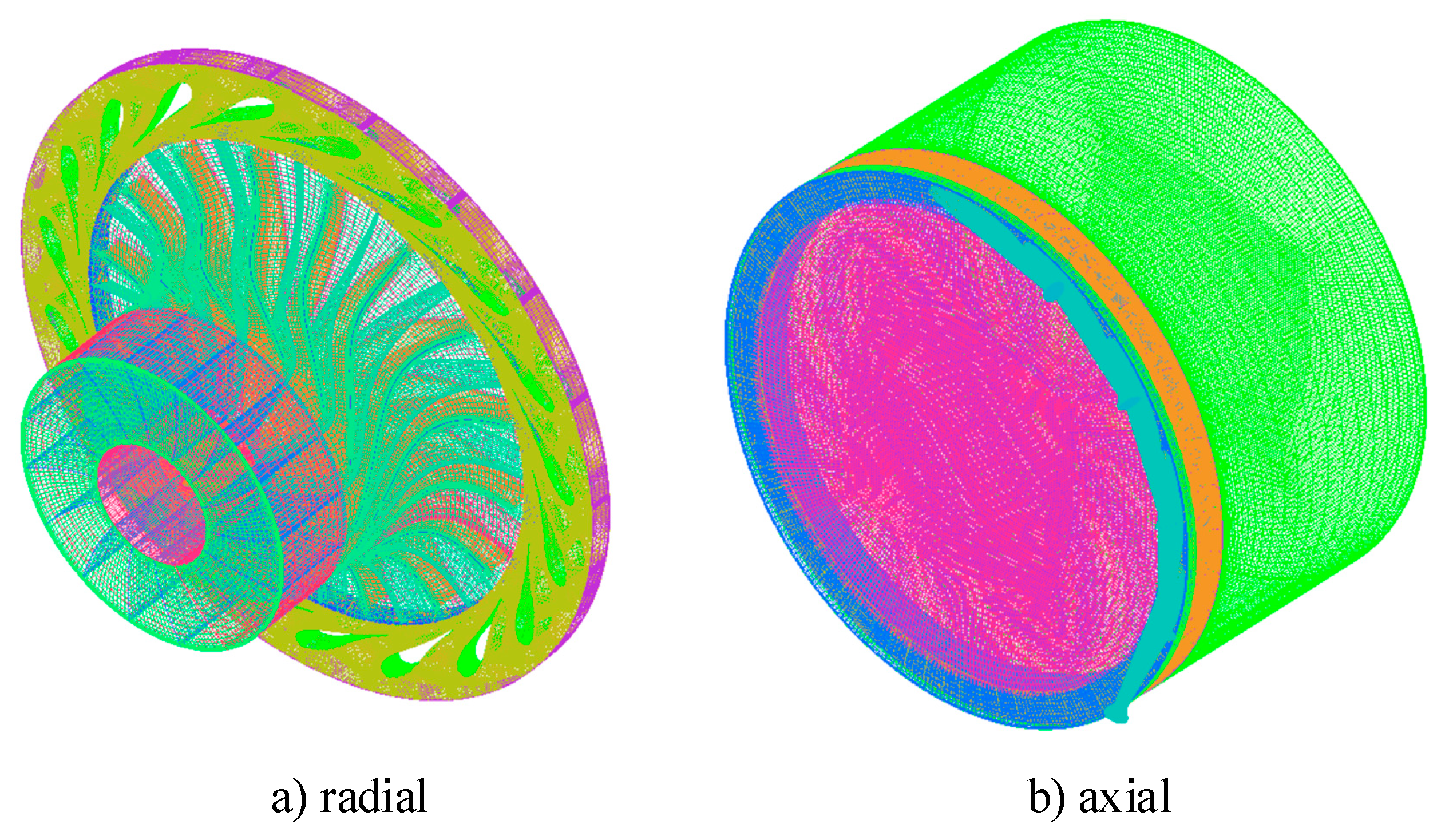
The CFD method is verified by comparing the simulation with the experiment. For radial inflow turbines, the experiment is selected using the turbine implemented in the T-100 Multipurpose Small Power Unit [47]. For axial turbines, the validation case of a small axial turbine used in a hydrocarbon fueled UUV is selected [7]. The boundary conditions are obtained by the experiment design point. The mesh independent study is performed based on three computational grids (coarse: 1500 K, medium: 2000 K and fine: 2500 K). As shown in Table 1, the difference between medium and fine meshes is less than 0.05%, and the medium mesh will be used for the following turbine analysis. The computational meshes for radial and axial turbines can be seen in Figure 5.
The mean-line and 3-D CFD total-to-static efficiencies are compared against the experimental result (see Table 2). Good agreement is achieved, and the maximum difference in the total-to-static efficiency is less than 5%, indicating that both the mean-line and numerical methods are well validated.

5. Results and Discussion

Now both the mean-line and numerical methods are well validated, the performances of axial and radial inflow turbines are compared for underwater vehicles.

5.1. Mean-Line Design Result

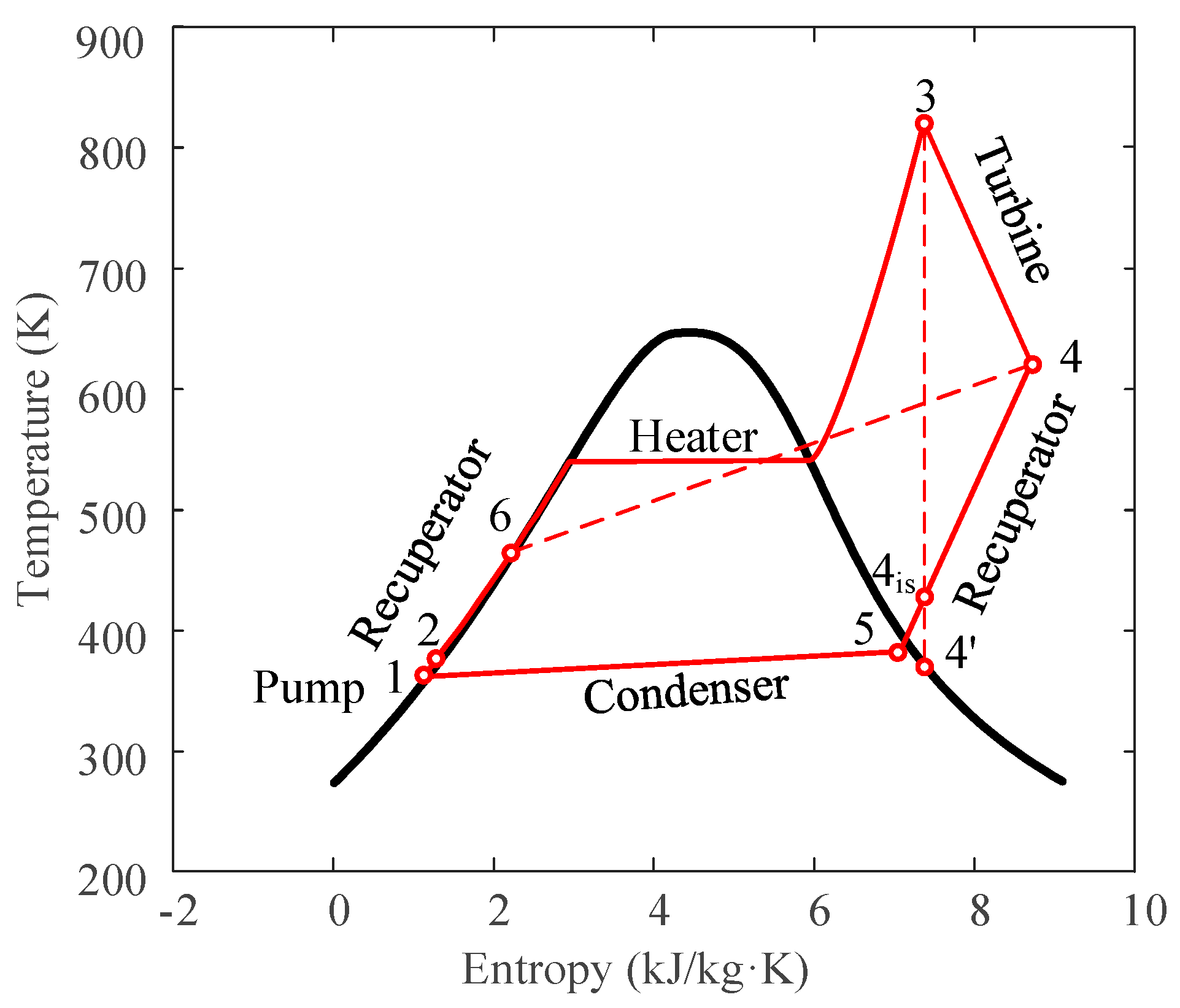
The thermodynamic cycle of the proposed steam Rankine cycle for UUVs is shown in Figure 6 [43,48]. Process 3–4 is the turbine expansion process, while 3–4 expresses the ideal isentropic expansion. As shown in Figure 6, a turbine inlet temperature of 823 K is selected, while the inlet pressure is 5 MPa. The outlet pressure is approximately 0.2 MPa.
Two cases with different output powers (11 kW and 75 kW) are selected, and this corresponds to the different partial admission ratios. Design constraints [43] are listed in Table 3. The radial clearance of the rotor is equal to 0.1 mm [49]. The thermodynamic properties are obtained from REFPROP 9.0.
For radial inflow turbines, Figure 7a–c shows the contour of efficiency (black), partial admission ratio (red) and absolute rotor inlet flow angle (blue) obtained from the mean-line method. The rotor radius ratio ε is initially set as 0.3 [24]. The flow coefficient 0.1 ≤ φ ≤0.3 and head coefficient 0.8 ≤ ϕ ≤2.4 are selected. The stator absolute velocity angle is limited to 80°. Therefore, the flow and head coefficients are selected as 0.2 and 1.2, respectively, as marked in Figure 7a. In addition, the results from Baines [28] and Ma [50] show that the outlet radius of the radial inflow turbine needs to be increased in microturbine applications, and the rotor radius ratio ε is then changed to 0.55. As shown in Figure 7b, the optimal flow and head coefficient are now chosen as 0.2 and 1.6. The partial admission ratio is larger than 0.8. The full-admission configuration can be realized by increasing the stator chord slightly. For the calculation of 11 kW, the rotor radius ratio ε is also set to 0.55, and the lower limit of ϕ is adjusted from 0.8 to 1.2 (see Figure 7c). Generally, the full-admission efficiency of the radial inflow turbine is higher than 80% at the low flow coefficient (~0.8), resulting in the low partial admission efficiency with low partial admission ratio. With the decrease in the output power, the optimal flow coefficient will gradually increase (Figure 7).
For axial turbines, Figure 7d shows the calculation results of axial turbines and the selected optimal points. It is noted that the stator angle for the axial turbine is typically set as 15°. A velocity ratio between 0.2 and 0.6 is selected for high partial admission, while 0.2~0.4 is for the low partial admission. Similar to radial inflow turbines, the optimal velocity ratio is decreased with the decreased output power.
The mean-line design results are summarized in Table A3 and Table A4 in Appendix B. The axial turbines present a high rotor number (five times the radial inflow turbine), and the edge thickness (0.21 mm for 75 kW and 0.13 mm for 11 kW) is smaller than radial inflow turbines (0.5 mm), which presents a negative influence on the strength performance.
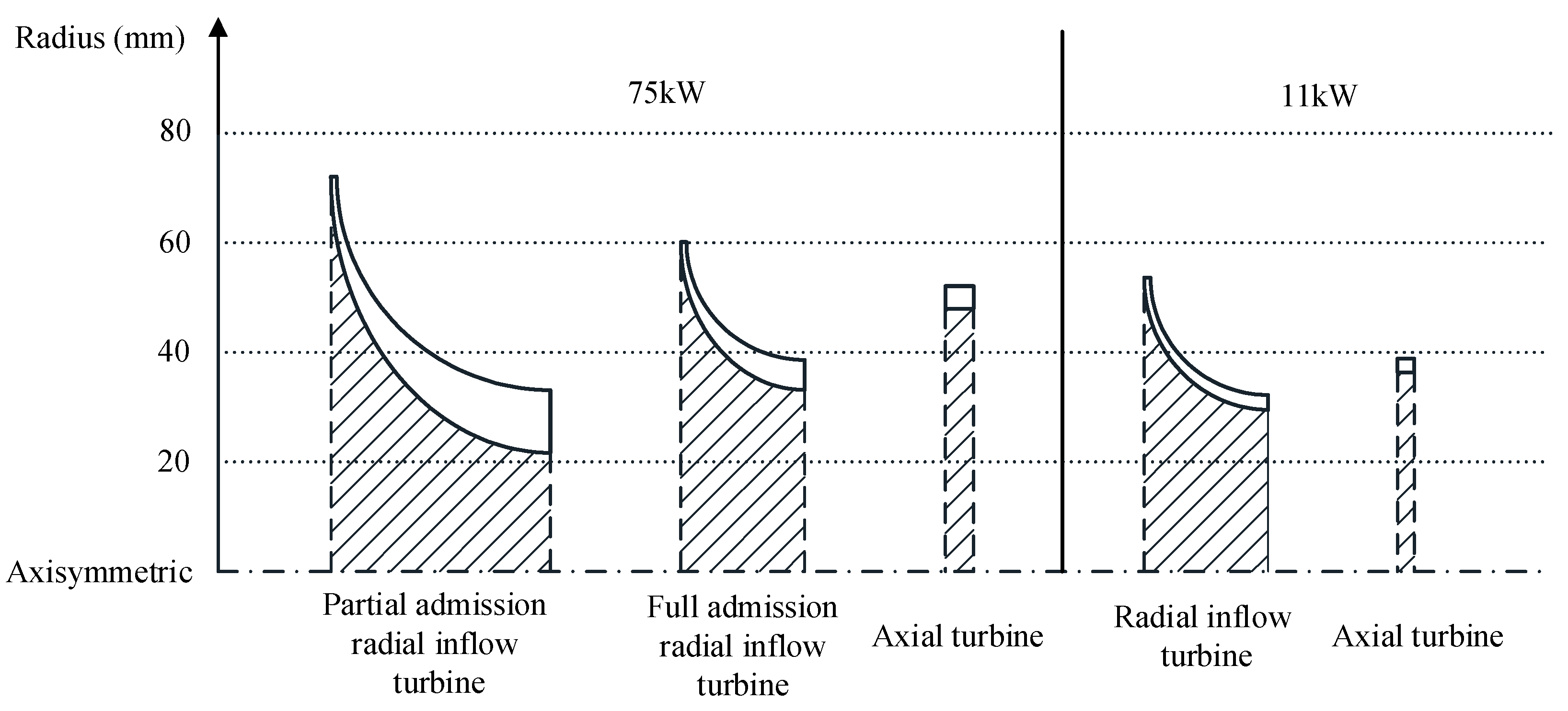
Figure 8 shows the meridional plane of the designed turbines. It is found that axial turbines have advantages in size at both axial and radial directions. The structure of axial turbines is compact and it is more suitable for limited space application. Additionally, the axial turbines can facilitate a larger blade height compared to radial inflow turbines. For radial inflow turbines, the blade height gradually increases from the inlet to outlet. At the rotor outlet, the blade height is larger than the axial turbines. This configuration makes the radial inflow turbines have less mechanical stress when the blade height is increased. In addition, with an inlet blade height around 1 mm and supersonic inlet velocity for radial inflow turbines, it is extremely different from existing applications. The rotor experiences relatively large clearance losses, increased viscous losses and a partial admission effect, especially at 11 kW.

5.2. Aerodynamic Performance

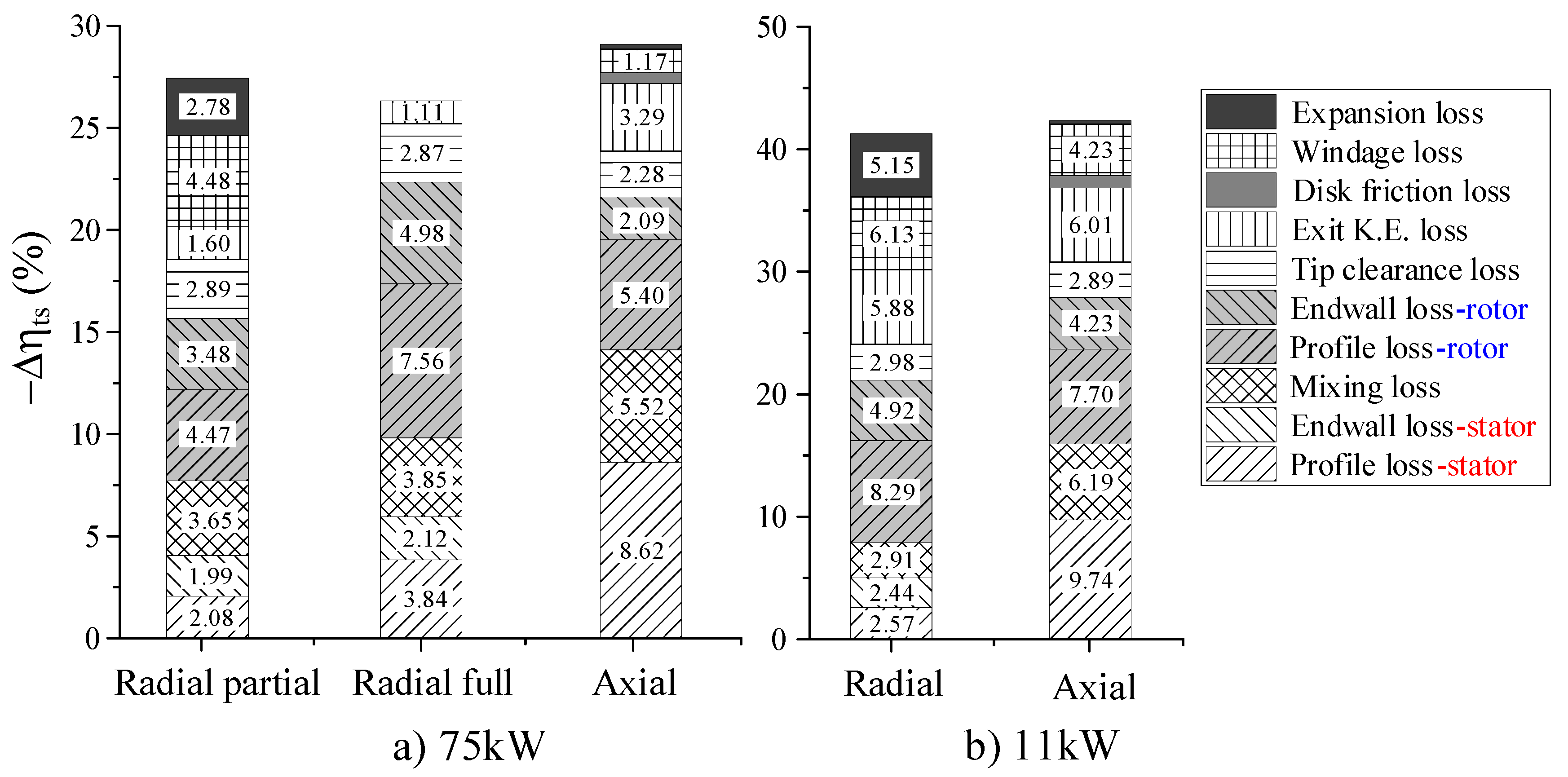
The radial and axial turbines obtained from the mean-line method are further assessed with the high-fidelity CFD method, and the comparison is listed in Table 4. Great agreement is achieved, and the relative difference is within 4%. It is shown that the performance of the radial inflow turbines is slightly higher than axial turbines. To provide more detail, the numerical loss breakdown study is performed based on the entropy rise at different surfaces with various computational setups. The losses are profile loss, endwall loss, mixing loss, tip clearance loss, exit kinetic energy loss and partial admission losses. The computational setup refers to Wheeler [51], Keep [52] and De Servi [49]. Table 5 shows the method of the numerical loss break-down used in this paper.
The profile loss is determined as the entropy rise over each component due to the blade boundary layer, trailing edge, and shock. The tip clearance, windage loss and expansion loss are considered the efficiency difference between different computational setups. The tip clearance loss describes the mixing of leaked and mainstream fluid combined with the friction loss at the shroud of the blade. The windage loss is caused by the centrifuging of the dead gas in the non-working segment. The expansion loss reflects the transient effect of partial admission when reentering the non-working or working segment. In addition, the exit kinetic energy loss reflects the dissipated kinetic energy at the rotor outlet. As shown in Table A3, the contribution of the disk friction loss to the total loss is less than 1%; therefore, the wheel is ignored in the radial inflow turbine modeling. Typically, the mixing-plane model is switched to the rotation-station interface. Due to the significant change at the interface caused by the shock wave and trailing edge wake, the loss decomposition of the rotor may be distorted. Therefore, the loss must also refer to the calculation results from the frozen rotor interface to achieve a reasonable result. Figure 9 shows a loss breakdown of the radial and axial turbine at different powers with the data of the efficiency loss contribution exceeding 1%.
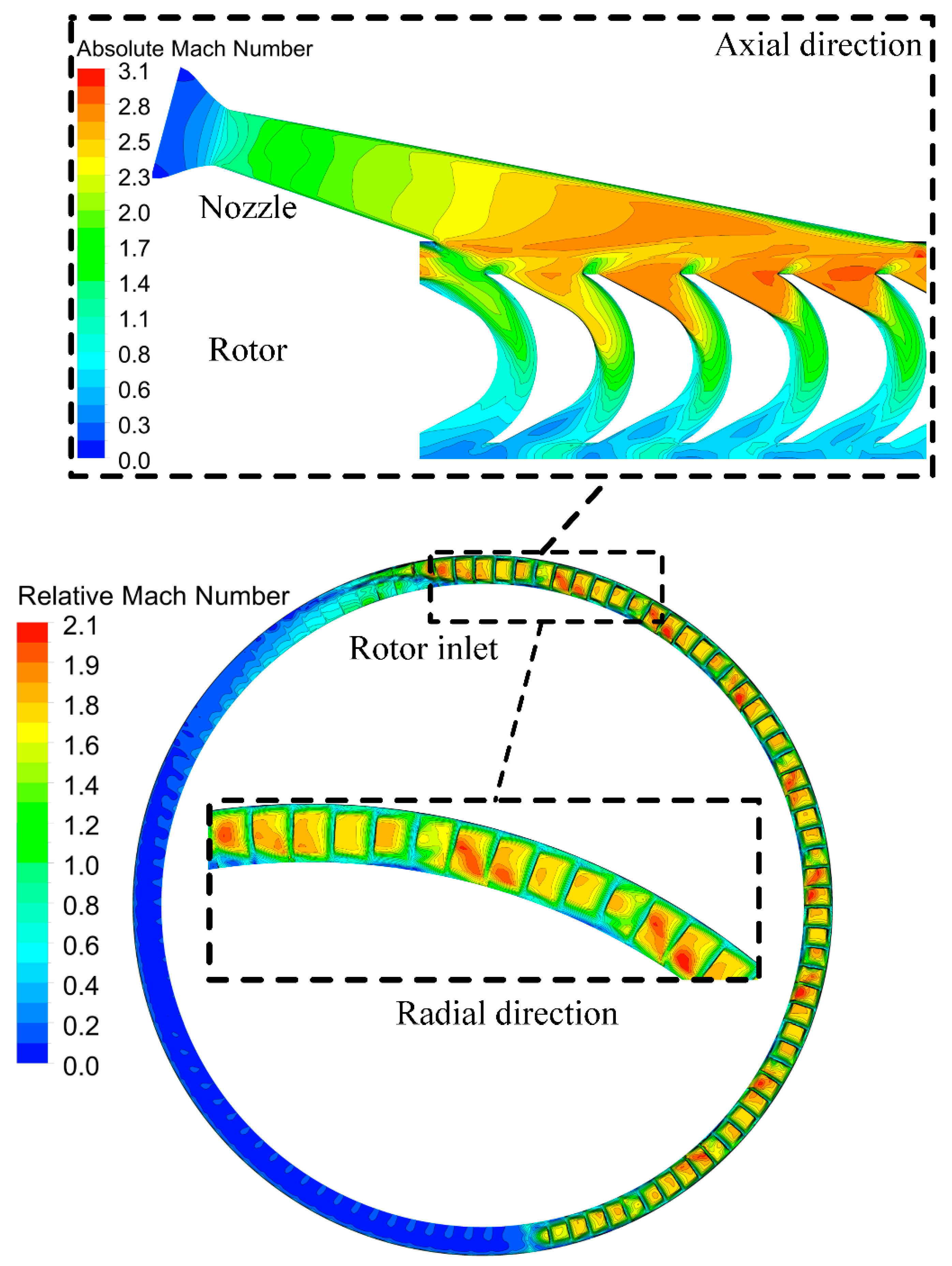
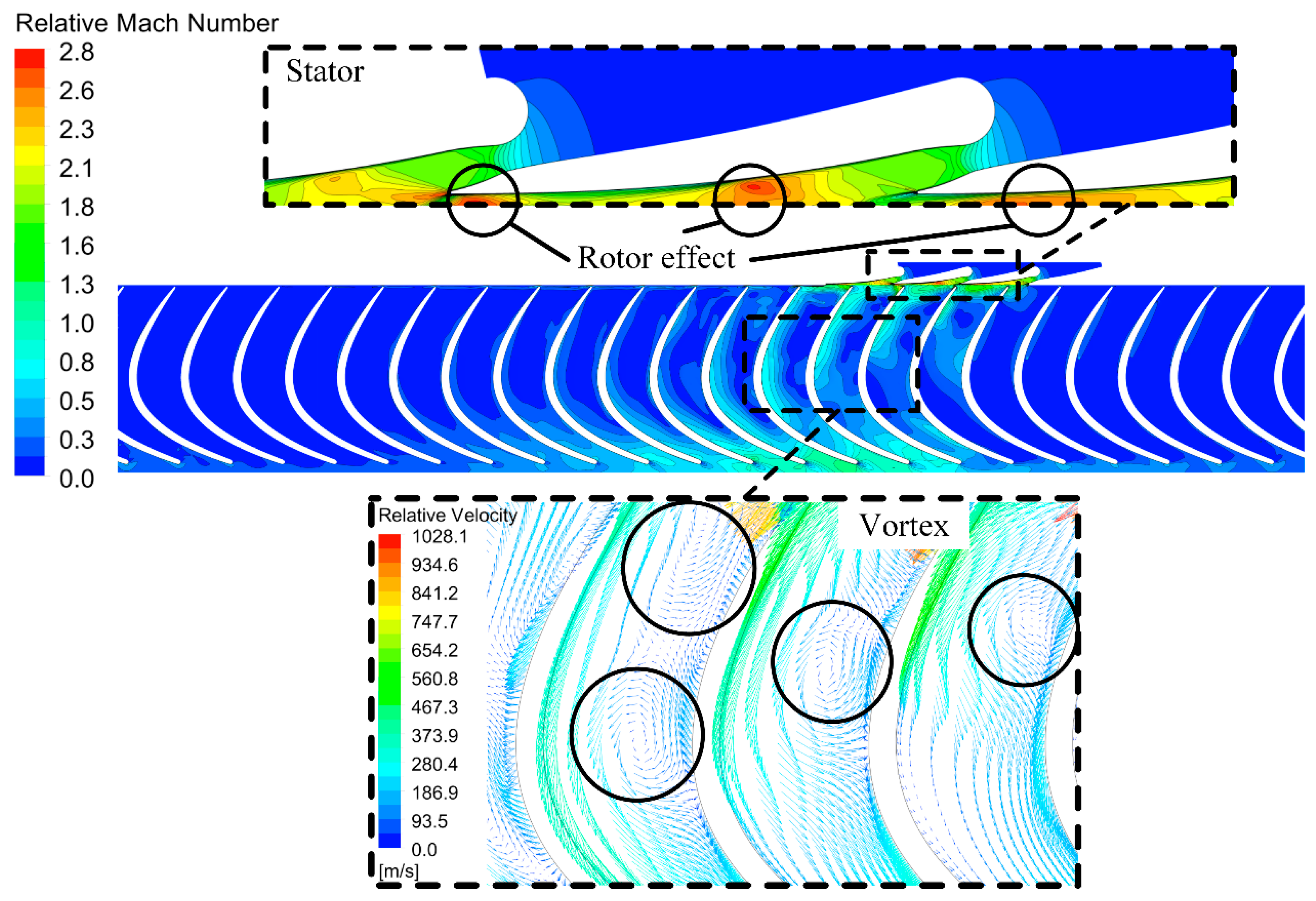
As shown in Figure 9, the stator loss of radial inflow turbines (7.72% for 75 kW partial admission; 9.81% for 75 kW full admission; 7.92% for 11 kW) is lower than that of the axial turbine (14.14% for 75 kW; 15.93% for 11 kW). For axial turbines, since the stator trailing edge is cut-off and irregular, this results in a large stator loss and mixing loss (see Figure 10). In addition, the straight-line shape of the expansion section makes the passage loss even higher. For radial inflow turbines, due to the longer chord of the stator after the expansion section, the flow at the outlet is greatly affected by the rotor leading edge, as shown in Figure 11. However, due to the smaller stator exit absolute velocity of the radial inflow turbines (75 kW full admission: 1016 m/s; 75 kW partial admission: 951.5 m/s; 11 kW: 985.4 m/s), the stator loss is lower than the axial turbines (1174 m/s).
For rotor loss, the length of the rotor blades is significantly longer than the axial turbines (in Figure 8), resulting in a decrease in efficiency of the radial inflow turbines due to the larger rotor passage losses at low velocity ratio (Figure 9 rotor losses). As shown in Figure 11, the working fluid only partially fills the rotor passage in the admitted channel because of the lower blade number and thinner rotor blade thickness. As shown in Figure 11 (Velocity vector), the supersonic flow and high absolute angle at the rotor inlet create the enhanced secondary flow loss. However, in Figure 10 Axial direction—Rotor, the flow in axial turbines is much smoother. Therefore, the loss caused by the blade shape of radial inflow turbines (7.56% for 75 kW full admission; 8.29% for 11 kW) is higher than the axial turbines (5.4% for 75 kW; 7.7% for 11 kW), while at 75 kW partial admission radial inflow turbine (4.47%), the profile loss is smaller due to the lower rotor inlet relative velocity.
The rotor loss of axial turbines cannot be further decreased, since the speed distribution of axial turbines with the circular-type stator at the rotor inlet is not uniform (Figure 10 Radial direction), and the flow characteristics in different sections are greatly different. Therefore, although the flow is more uniform in the axial direction, the difference in the radial direction is still large. In addition, due to the high continuous blade height from the rotor inlet to outlet, the end wall (Radial inflow turbine: 3.48% for 75 kW partial admission; 4.98% for 75 kW full admission; 4.92% for 11 kW. Axial turbine: 2.09% for 75 kW; 4.23% for 11 kW) and tip clearance loss (Radial inflow turbine: 2.89% for 75 kW partial admission; 2.87% for 75 kW full admission; 2.98% for 11 kW. Axial turbine: 2.28% for 75 kW; 2.89% for 11 kW) of the axial turbines is lower than the radial inflow turbines. Moreover, the exit K.E. loss of radial inflow turbines (1.6% for 75 kW partial admission; 1.11% for 75 kW full admission; 5.88% for 11 kW) is smaller than the axial turbines (3.29% for 75 kW; 6.01% for 11 kW) because of the lower rotor exit radius. The 11 kW radial inflow turbine has a higher exit K.E. loss (5.88%) close to the axial turbine (6.01%) because of the blade height reduction at the rotor outlet.
The partial admission losses of the radial inflow turbines (7.26% for 75 kW; 11.28% for 11 kW) are significantly higher than the axial turbines (1.38% for 75 kW; 4.47% for 11 kW). The longer rotor blades of radial inflow turbines have a larger blade passage volume, which directly causes the increment of dead gas in the non-working segment. This leads to more centrifugal force to rotate the dead gas. Therefore, the windage loss for radial inflow turbines (4.48% for 75 kW; 6.13% for 11 kW) is higher than the axial turbines (1.17% for 75 kW; 4.23% for 11 kW) (Figure 9). The strong transient effects in the rotor lead to an extremely high loss. When the rotor enters the working segment, the dead gas needs to be pumped out. Due to the larger volume of dead gas and longer blades in the radial inflow turbine passage, more energy is required to push the dead gas out of the turbine. Radial inflow turbines are inferior in terms of partial admission losses. However, because of the higher full-admission efficiency, the efficiency with a partial admission structure is not much different from the axial turbine.
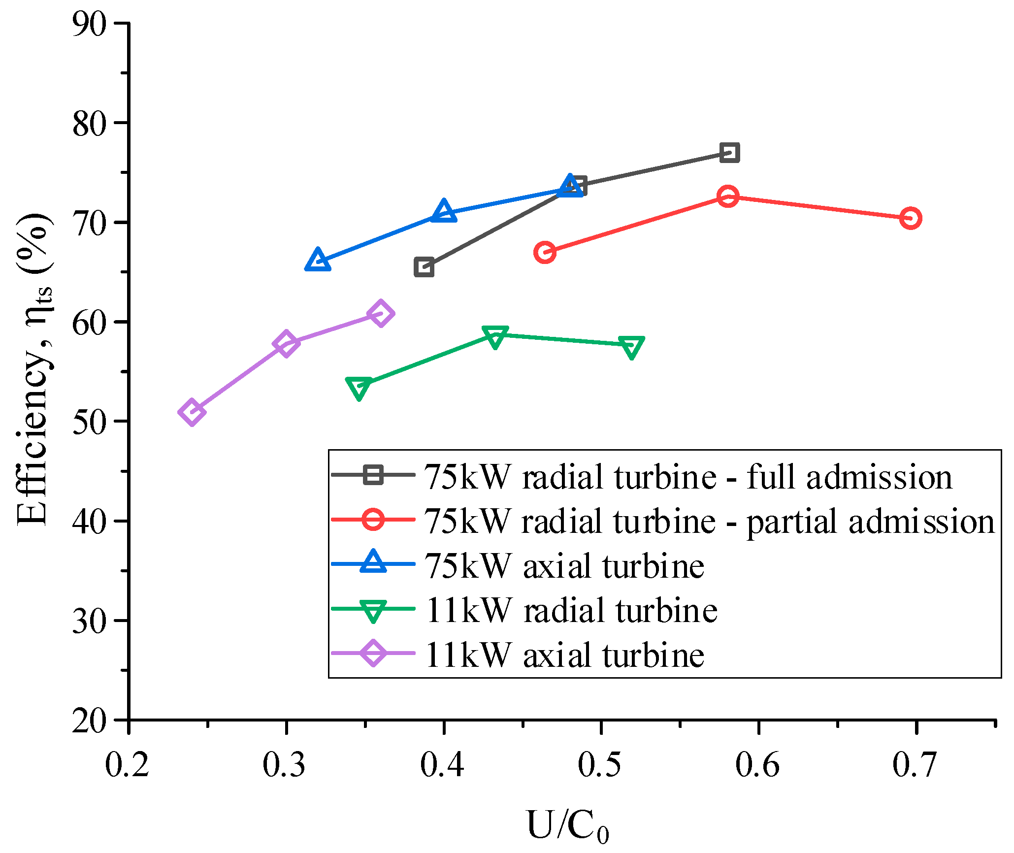
The turbine off-design performance is also essential for the UUV power system. Figure 12 shows the variation in the total-to-static efficiency as a function of the velocity ratio. The results are calculated by keeping the pressure ratio constant while varying the rotational speed from 80% to 120% of its nominal value. For the full-admission radial inflow turbine, it is not suitable at a velocity ratio under 0.5. For partial admission radial inflow turbines, the efficiency is still higher than axial turbines at the low rotational speed. However, with the rotor inlet diameter of radial inflow turbines further increasing the velocity ratio, the axial turbines still have a great advantage at low velocity ratio.

5.3. Strength Comparison

To evaluate the strength performance, the von Mises stress distribution is determined by the ANSYS Structural module. The blade is made of a nickel chromium INCONAL 718 [24] material with a mass density of 8220 kg/m3. The Young’s modulus and Poisson’s ratio of the material are 127 GPa and 0.4, respectively. A fixed support condition is set at the hub of the blade, and a rotation speed of 100,000 rpm around the z axis is also prescribed. In addition, the aerodynamic force is then considered by full admission steady-state node pressure transformed from fluid to structure.
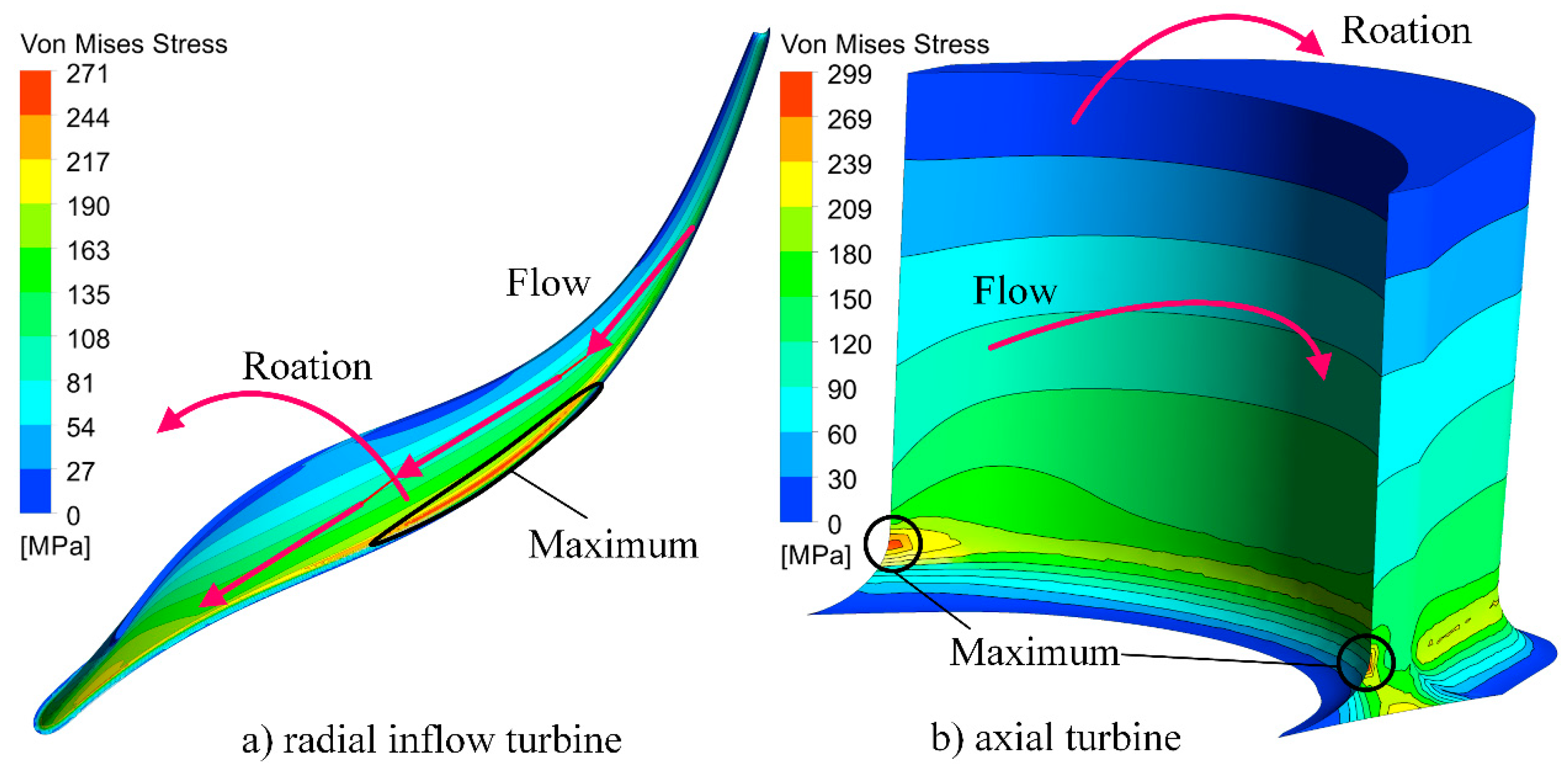
The structural analysis results show that the maximum equivalent stress of radial inflow turbines is smaller than axial turbines (see Table 6). The distribution of von Mises stress of the blade is shown in Figure 13. The maximum Von Mises stress for radial inflow turbines is at the middle of the blade, while for axial turbines it is at the leading and trailing edge of the blade. The result shows that although the radius at the rotor inlet is the highest, the lower inlet blade height of the radial inflow turbines results in the smaller centrifugal force. Similarly, the hub radius is small at the exit with the highest blade height; therefore, the strength is still small. Therefore, the radial inflow turbine can have a higher speed ratio than the axial turbine under better stress conditions. However, the radial inflow turbine requires the proper blade profile design to achieve this result. Sometimes, undesirable design not only affects turbine efficiency, but also concentrates stress at the inlet or outlet like the axial turbine. In addition, since the blade height for 11 kW is smaller than the 75 kW (Table A3 and Table A4), the torque generated by the supersonic flow on the bottom of the blade will be reduced. Therefore, the influence of aerodynamics decreases with the reduction in the output power.
6. Conclusions

This paper presents the comparison of axial and radial inflow turbines applied to UUVs in terms of size, aerodynamics and structural performance, and the suitable turbine configuration is compared. The key findings are:
(1) The size of axial turbines is small in both axial and radial directions compared to radial inflow turbines. In addition, by considering the size of the volute and stator, the size of radial inflow turbines is approximately twice as large as that of axial turbines at the same output power.
(2) The radial inflow turbines can achieve a higher efficiency with the full admission configuration, but partial admission losses are larger than axial turbines. Therefore, the turbine efficiency is approximately the same and the difference between axial and radial inflow turbines is less than 4%.
(3) The radial inflow turbine has a small inlet blade height and rotor outlet radius. Therefore, the blade structural performance of radial inflow turbines is better than axial turbines. The maximum Von Mises stress of radial turbines can be reduced to approximately 10% to 30% of the axial turbines.
It is noted that the efficiency of the radial inflow turbine is only slightly higher than the axial turbine under supersonic and partial admission conditions. Even though the radial inflow turbine performs better in stress distribution and efficiency, it is still too large to be used in UUVs. Therefore, the axial turbine is preferred for this particular application.

Author Contributions

Conceptualization, H.W.; funding acquisition, K.Q.; investigation, K.L.; methodology, H.W., Y.C. and T.T.; resources, K.L.; writing—original draft, H.W.; writing—review and editing, Y.C., T.T. and K.Q. All authors have read and agreed to the published version of the manuscript.

Funding

This research is supported by the National Natural Science Foundation of China (NSFC) (Grant No. 51805435), the Fundamental Research Funds for the Central Universities and Natural Science Basic Research Plan in Shaanxi Province of China (Grant No. 2019JQ-159).

Institutional Review Board Statement

Not applicable.

Informed Consent Statement

Not applicable.

Data Availability Statement

Not Applicable.

Acknowledgments

The authors would like to thank the National Natural Science Foundation of China (NSFC) and the Fundamental Research Funds for the Central Universities and Natural Science Basic Research Plan in Shaanxi Province of China for the sponsorship.

Conflicts of Interest

The authors declare no conflict of interest.

Highlights

  • Two cases under supersonic and partial admission conditions are designed for axial and radial inflow turbines.
  • Axial and radial inflow turbines are compared in size, aerodynamics and strength performance.
  • The axial turbine is confirmed more suitable for underwater vehicles.
Nomenclature η Efficiency
A Area, m2 θ Angle between two stators, °
a 1 Coefficient λ Thermal conductivity, kg·m/(s3·K)
B Pressure ratio μ Molecular (dynamic) viscosity, kg/(m·s)
C Absolute flow velocity, m/s μ t Turbulent viscosity, kg/(m·s)
C x , C r Loss model multiplier υ t Eddy-viscosity, m2/s
c Blade chord, m ξ Meridional velocity ratio
d Diameter, m ρ Density, kg/m3
e Partial admission ratio σ k 3 Turbulence model constant for the k equation
F 1 , F 2 Blending function σ ω 3 , σ ω 2 k- ω turbulence model constant
{ f } External force vector, N τ Molecular stress tensor, kg/(m·s2)
g Gravitational acceleration, m/s2 ϕ Flow coefficient
h Specific enthalpy, J/kg; Blade height, m φ Coefficient
M Mach number; Moment, N·m χ Velocity ratio
K Factor; Relative velocity ratio ψ Head coefficient
K p , K p l , K w Loss model multiplier ω Rotation speed, rad/s; Turbulent frequency, s−1
( K ) Stiffness matrices, N/mSubscripts
k Coefficient; Turbulence kinetic energy per unit mass, m2/s2 0 Absolute
l Length, m 1 Stator inlet
m ˙ Mass flow rate, kg/s 3 Stator outlet
m Meridional extension 4 Rotor inlet
P Power, W; Blade pitch, m 6 Rotor outlet
P k Production rate of turbulence, kg/(m·s3) a Actual
P k b , P ω b Buoyancy turbulence terms, kg/(m·s3), kg/(m3·s2) c r Critical
p Pressure, Pa e Exit
R 1 , R 2 Pressure/Suction side radius, m exp Expansion
Re Reynolds number f Factor; Friction
r Radius, m f r Friction
S E Energy source, kg/(m·s3) f u l l Full admission
S M Momentum source, kg/(m2·s2) h Hydraulic; Hub
S Invariant measure of the strain rate i s Ideal enthalpy drop
s Edge thickness, m; Arc length of one passage, m; Rotor meridional length, m m Mass flow; Mean
T Temperature, K o p t Optimal
t Thickness, m; Circumferential direction, °; Time, s p Pressure
U Vector of velocity, m/s p a r Partial admission
U Peripheral velocity, m/s p e Post-expansion
U j Mean velocity in tensor notation, m/s r Rotor; Radial direction
{ U } Displacement vector, m r e l Relative
W Relative velocity, m/s r m s Root mean square
w Passage width, m s Stator
x j Position vector in tensor notation, m T Temperature
y + Non-dimensional grid spacing at wall t Theory; Tip
Z Blade number t e Trailing edge
Greek Symbols t o t Total
α Absolute flow angle, ° t s Total to static
α 3 Coefficient in k-ω turbulence model u Wheel
β Relative flow angle, ° v Velocity
β , β 3 Coefficient in k-ω turbulence model w Windage
γ Specific heat ratio; Expansion angle, ° θ Tangential
ε Clearance, m; Rotor (outlet/inlet) radius ratio x Axial direction

Appendix A. Loss Model for Axial and Radial Inflow Turbine

Table A1. Loss Models for Radial Inflow Turbine.
Loss MechanismLoss Model
Rotor Losses
Incidence loss Δ h i n c i d e n c e = W θ 4 2 2 sin n ( β 4 β 4 , o p t ) , n = { 2 , β 4 β 4 , o p t < 0 3 , β 4 β 4 , o p t > 0
Passage loss Δ h p a s s a g e = K p { ( l h d h ) + 0.68 [ 1 ( r ¯ 6 r 4 ) 2 cos β 6 ( h 6 / c ) ] } 1 2 ( W 4 2 + W 6 2 ) 2
Trailing edge loss Δ h t e = 2 γ M 6 , r e l 2 ρ 6 W 6 , r m s 2 2 g P 6 , t o t , r m s ( Z r t π ( r 6 t + r 6 h ) cos ( β 6 , r m s ) ) 2
Exit energy loss Δ h e x i t = 0.5 C 6 2
Tip clearance loss Δ h t i p = U 4 4 l r 8 π ( 0.4 ε x C x + 0.75 ε x C x 0.3 ε x ε r C x C r )
Disk friction loss Δ h f = 1 4 ρ k f ω 2 r 4 2
Stator losses
Passage loss Δ h p a s s a g e , s = K p l 0.05 Re 3 0.2 [ 3 tan α 3 s 3 / c s + s 3 cos α 3 b 3 ] 1 2 C 3 2
Trailing edge loss Δ h t e , s = ( Z s t 3 2 π r 3 cos α 3 ) 2 1 2 C 3 2 [ 1 + γ 1 2 M 3 2 ] γ 1 γ
Post-expansion loss Δ h p e , n o z = ( M 3 M 2 M 3 ) 2 1 2 C 3 2 [ 1 + γ 1 2 M 3 2 ] γ γ 1
Partial admission losses
Windage loss Δ h w = K w ( 1 e ) π d m h m ( ρ m / 2 ) U m 3 / m ˙
Expansion loss Δ h exp = [ K / ( 1 + K ) ] ( s / 3 a ) η t s Δ h i s
Table A2. Loss Models for Axial Inflow Turbine.
Loss MechanismLoss Model
Stator loss
Stator passage loss V 3 = φ v , s 2 Δ h i s
Rotor losses
Rotor passage loss φ v , r = 0.95 0.00015 W 4
Disk friction loss P f = 1.2 10 3 ( U m 100 ) 3 d m 2 ρ m
Tip clearance loss η t i p = 1 1.725 ε r h r
Exit energy loss Δ h e x i t = 0.5 C 6 2
Partial Admission Losses
Windage loss P w = 7.5 10 4 ( 1 e ) d m h r ( U m 100 ) 3 ρ m
Expansion loss P exp = 0.078 c r h r A e U m η u h 6 h 01 m ˙

Appendix B. Results Obtained from Mean-Line Design

Table A3. Mean-line Design Result of Radial Inflow Turbines.
ParameterUnits75 kW Partial75 kW Full11 kW
Flow coefficients, φ-0.20.20.21
Head coefficients, ψ-1.21.61.8
Rotor (outlet/inlet) radius ratio, ε-0.30.550.55
Meridional velocity ratio, ξ -1.01.01.0
Admission fraction, e-0.43110.8756 (1.0)0.1702
Reaction, ρ -0.44470.32000.3152
Specific speed ,   n s ( N s )-0.1367 (17.6313)0.1389 (17.9240)0.0622 (8.0233)
Velocity ratio, χ -0.58030.48450.4326
Stator   inlet   radius ,   r 1 mm837061
Stator   outlet   radius ,     r 3 mm72.560.754.1
Stator   blade   height ,   h 1 ,   h 3 mm1.01211.01571.1413
Stator   outlet   absolute   flow   angle ,   α 3 °80.537782.875083.3456
Stator   number   of   vanes ,   Z s -9203
Rotor   inlet   radius ,   r 4 mm72.081960.169153.6534
Rotor   inlet   blade   height ,   h 4 mm1.01211.01571.1413
Rotor   outlet   blade   height ,   h 6 mm11.47225.50892.6936
Rotor   outlet   hub   radius ,   r 6 h mm21.624633.093029.5094
Rotor   outlet   shroud   radius ,   r 6 t mm33.096838.601932.2029
Axial   clearance ,   ε a mm0.10.10.1
Radial   clearance ,   ε r mm0.10.10.1
Backface   clearance ,   ε b mm0.10.10.1
Rotor   inlet   absolute   flow   angle ,   α 4 °80.537782.875083.3456
Rotor   inlet   relative   flow   angle ,   β 4 °4571.565175.2917
Rotor   outlet   absolute   flow   angle ,   α 6 °000
Rotor   outlet   relative   flow   angle ,   β 6 °−62.7203−71.4942−69.9577
Rotor   number   of   blades ,   Z r -192223
Stator passage loss contribution%3.43795.51165.8321
Stator expansion loss contribution%1.57442.75102.8115
Stator trailing edge loss contribution%0.23100.46480.5452
Rotor incidence loss contribution%2.25097.01768.5035
Rotor passage loss contribution%5.05545.15826.8464
Rotor trailing edge loss contribution% 0 0 0
Rotor tip clearance loss contribution%5.22743.00902.8918
Rotor disk fraction loss contribution%0.05030.03790.0299
Windage loss contribution%3.44970.33724.1575
Expansion loss contribution%5.34451.37715.8521
Exit energy loss contribution%1.34710.93895.1585
Total-to-static efficiency, η t s p a r %72.0373.4057.37
Table A4. Mean-line Design Result of Axial Inflow Turbines.
ParameterUnits75 kW11 kW
Pitch   diameter ,   d m mm100.062975.1895
Number   of   blades ,   Z r -106133
Blade height, hmm4.16952.5034
Blade chord, cmm5.14233.0876
Inlet   angle ,   β i n °27.840323.8303
Exit   angle ,   β o u t °27.840323.8303
Edge thickness, smm0.20850.1252
Stator   number ,   Z s -105
Admission fraction, e-0.45520.1823
Reaction, ρ -00
Specific   speed ,   n s ( N s ) 0.1323 (17.0660)0.0562 (7.2507)
Stator   throat   diameter ,   d c r mm1.75991.0501
Stator   exit   diameter ,   d e mm3.47452.0862
Stator angle ,   α s °1515
Velocity ratio, χ -0.40.3
Radial   clearance ,   ε r mm0.10.1
Axial   clearance ,   ε a mm11
Stator loss contribution%8.45658.1087
Rotor blade loss contribution%11.059416.4822
Exit energy loss contribution%4.47047.6675
Tip clearance loss contribution%3.14644.6711
Disk friction loss contribution%1.64622.1848
Windage loss contribution%2.33563.7155
Expansion loss contribution%0.76381.0230
Total-to-static efficiency, η t s %68.1256.15

References

  1. French, D.W. Analysis of Unmanned Undersea Vehicle (UUV) Architectures and an Assessment of UUV Integration into Undersea Applications. Ph.D. Thesis, Naval Postgraduate School, Monterey, CA, USA, 2010. [Google Scholar]
  2. Eagle, W.; Waters, D.; Cadou, C. System Modeling of a Novel Aluminum Fueled UUV Power System. In Proceedings of the 50th AIAA Aerospace Sciences Meeting including the New Horizons Forum and Aerospace Exposition, Nashville, TN, USA, 9–12 January 2012. Paper No: 2012-1135. [Google Scholar]
  3. Harper, A.D. Thermochemical power systems for underwater applications. In Proceedings of the 6th International Symposium on Unmanned Untethered Submersible Technology, Durham, NH, USA, 12–14 June 1989; pp. 136–152. [Google Scholar]
  4. Miller, T.F.; Walter, J.; Kiely, D. A next-generation AUV energy system based on aluminum-seawater combustion. In Proceedings of the 2002 Workshop on Autonomous Underwater Vehicles, San Antonio, TX, USA, 20–21 June 2002; pp. 111–119. [Google Scholar]
  5. Hughes, T.G.; Smith, R.B.; Kiely, D.H. Stored chemical energy propulsion system for underwater Applications. J. Energy 1983, 7, 128–133. [Google Scholar] [CrossRef]
  6. Epstein, K.C. Torpedo; Harvard University Press: Cambridge, MA, USA, 2014. [Google Scholar]
  7. Kiely, D.; Moore, J. Hydrocarbon fueled UUV power systems. In Proceedings of the 2002 Workshop on Autonomous Underwater Vehicles, San Antonio, TX, USA, 20–21 June 2002. [Google Scholar]
  8. Dorney, D.; Griffin, L.; Sondak, D. Full- and partial-admission performance of the simplex turbine. J. Propuls. Power 2004, 3, 486–491. [Google Scholar] [CrossRef] [Green Version]
  9. Yada, K.; Uchiumi, M.; Funazaki, K.-I. Thomas/alford force on a partial-admission turbine for the rocket engine turbopump. J. Fluids Eng. 2018, 141, 011105. [Google Scholar] [CrossRef]
  10. Dixon, S.L.; Hall, C.A. Fluid Mechanics and Thermodynamics of Turbomachinery, 6th ed.; Butterworth-Heinemann/Elsevier: Burlington, MA, USA, 2010. [Google Scholar]
  11. Copeland, C.D.; Martinez-Botas, R.; Seiler, M. Unsteady performance of a double entry turbocharger turbine with a com-parison to steady flow conditions. J. Turbomach. 2012, 134, 021022. [Google Scholar] [CrossRef]
  12. Xue, Y.; Yang, M.; Martinez-Botas, R.F.; Romagnoli, A.; Deng, K. Loss analysis of a mix-flow turbine with nozzled twin-entry volute at different admissions. Energy 2019, 166, 775–788. [Google Scholar] [CrossRef]
  13. Sun, H.; Qin, J.; Yan, P.; Huang, H.; Hung, T.-C. Performance evaluation of a partially admitted axial turbine using R245fa, R123 and their mixtures as working fluid for small-scale organic Rankine cycle. Energy Convers. Manag. 2018, 171, 925–935. [Google Scholar] [CrossRef]
  14. Rzadkowski, R.; Zywica, G.; Kaczmarczyk, T.Z.; Koprowski, A.; Kowalski, M. Design and investigation of a partial admission radial 2.5-kW organic Rankine cycle micro-turbine. Int. J. Energy Res. 2020, 44, 11029–11043. [Google Scholar] [CrossRef]
  15. Huang, G.; Shu, G.; Tian, H.; Shi, L.; Zhuge, W.; Zhang, J.; Atik, M.A.R. Development and experimental study of a super-critical CO2 axial turbine applied for engine waste heat recovery. Appl. Energy 2020, 257, 113997. [Google Scholar] [CrossRef]
  16. Shin, H.; Cho, J.; Baik, Y.J.; Cho, J.; Huh, J. Partial admission, axial impulse type turbine design and partial admission radial turbine test for SCO2 cycle. In Proceedings of the ASME Turbo Expo 2017: Turbomachinery Technical Conference and Exposition, Charlotte, NC, USA, 26–30 June 2017. [Google Scholar]
  17. Balje, O.E.; Japikse, D. Turbomachines—A Guide to Design Selection and Theory; John Wiley& Sons: Hoboken, NJ, USA, 1981. [Google Scholar]
  18. Japikse, D.; Baines, N. Introduction to Turbomachinery; Concepts ETI, Inc.: Norwich, VT, USA; Oxford University Press: Norwich, VT, USA, 1994. [Google Scholar]
  19. Dunham, J.; Panton, J. Experiments on the design of a small axial turbine. In Proceedings of the Conference on Heat and Fluid Flow in Steam and Gas Turbine Plant, Coventry, UK, 3–5 April 1973; pp. 56–65. [Google Scholar]
  20. Branchini, L.; De Pascale, A.; Peretto, A. Systematic comparison of ORC configurations by means of comprehensive perfor-mance indexes. Appl. Therm. Eng. 2013, 61, 129–140. [Google Scholar] [CrossRef]
  21. Daabo, A.M.; Mahmoud, S.; Al-Dadah, R.K.; Al Jubori, A.M.; Ennil, A.B. Numerical analysis of small scale axial and radial turbines for solar powered Brayton cycle application. Appl. Therm. Eng. 2017, 120, 672–693. [Google Scholar] [CrossRef]
  22. Bahamonde, S.; Pini, M.; Servi, C.D.; Rubino, A.; Colonna, P. Method for the preliminary fluid dynamic design of high-temperature mini-ORC turbines. J. Eng. Gas Turbines Power 2017, 139, 082606. [Google Scholar] [CrossRef]
  23. Weiß, A.P.; Popp, T.; Müller, J.; Hauer, J.; Brüggemann, D.; Preißinger, M. Experimental characterization and comparison of an axial and a cantilever micro-turbine for small-scale Organic Rankine Cycle. Appl. Therm. Eng. 2018, 140, 235–244. [Google Scholar] [CrossRef]
  24. Ventura, C.A.; Jacobs, P.A.; Rowlands, A.S.; Petrie-Repar, P.; Sauret, E. Preliminary design and performance estimation of radial inflow turbines: An automated approach. J. Fluids Eng. 2012, 134, 031102. [Google Scholar] [CrossRef]
  25. Baines, N.C.; Whitfield, A. Design of Radial Turbomachines; Longman Scientific and Technical: Essex, UK, 1990. [Google Scholar]
  26. Persky, R.; Sauret, E. Loss models for on and off-design performance of radial inflow turbomachinery. Appl. Therm. Eng. 2019, 150, 1066–1077. [Google Scholar] [CrossRef]
  27. Wasserbauer, C.A.; Glassman, A.J. FORTRAN Program for Predicting off-Design Performance of Radial-Inflow Turbines; NASA Lewis Resedrcb Center: Washington, DC, USA, 1975. [Google Scholar]
  28. Moustapha, H.; Zelesky, M.F.; Baines, N.C.; Japikse, D. Axial and Radial Turbines; Concepts NREC: White River Junction, VT, USA, 2003. [Google Scholar]
  29. Ghosh, S.K.; Sahoo, R.K.; Sarangi, S.K. Mathematical analysis for off-design performance of cryogenic turboexpander. J. Fluids Eng. 2011, 133, 031001. [Google Scholar] [CrossRef]
  30. Suhrmann, J.F.; Peitsch, D.; Gugau, M.; Heuer, T.; Tomm, U. Validation and development of loss models for small size radial turbines. In Proceedings of the ASME Turbo Expo 2010: Power for Land, Sea, and Air, Glasgow, UK, 14–18 June 2010. Paper No: GT2010-22666. [Google Scholar]
  31. Rodgers, C. Mainline Performance Prediction for Radial Inflow Turbine in Small High Pressure Ratio Turbine; Von Karman Institute Lecture Series; Sundstrand Turbo: Pacoima, CA, USA, 1987. [Google Scholar]
  32. Glassman, A.J. Enhanced Analysis and Users Manual for Radial-Inflow Turbine Conceptual Design Code RTD; NASA Lewis Resedrcb Center: Washington, DC, USA, 1995. [Google Scholar]
  33. Aungier, R.H. Turbine Aerodynamics–Axial Flow and Radial Flow Turbine Design; ASME Press: New York, NY, USA, 2005. [Google Scholar]
  34. Suter, P.; Traupel, W. Untersuchungen über den Ventilationsverlust von Turbinenrädern; Verlag Leemann: Zürich, Switzerland, 1959. [Google Scholar]
  35. Stenning, A.H. Design of Turbines for High-Energy-Fuel Low-Power-Output Applications; MIT Dynamic Analysis and Control Laboratory: Cambridge, MA, USA, 1953. [Google Scholar]
  36. Seo, J.; Han, S. Supersonic turbine stator design using dense gas with numerical method. J. Mech. Sci. Technol. 2017, 31, 4297–4303. [Google Scholar] [CrossRef]
  37. Anand, N.; Vitale, S.; Pini, M.; Otero, G.J.; Pecnik, R.; Otero-Rodríguez, G.J. Design Methodology for supersonic radial vanes operating in nonideal flow conditions. J. Eng. Gas Turbines Power 2019, 141, 022601. [Google Scholar] [CrossRef]
  38. Glassman, A.J. Computer Program for Design Analysis of Radial-Inflow Turbines; NASA Lewis Resedrc Center: Washington, DC, USA, 1976. [Google Scholar]
  39. Wheeler, A.P.S.; Ong, J. the role of dense gas dynamics on organic rankine cycle turbine performance. J. Eng. Gas Turbines Power 2013, 135, 102603. [Google Scholar] [CrossRef]
  40. Pini, M.; De Servi, C.; Burigana, M.; Bahamonde, S.; Rubino, A.; Vitale, S.; Colonna, P. Fluid-dynamic design and charac-terization of a mini-ORC turbine for laboratory experiments. Energy Procedia 2017, 129, 1141–1148. [Google Scholar] [CrossRef]
  41. Ohlsson, G.O. Partial-Admission Turbines. J. Aerosp. Sci. 1962, 29, 1017–1023. [Google Scholar] [CrossRef]
  42. Linhardt, H.D.; Silvern, D.H. Analysis of partial admission axial impulse turbines. ARS J. 1961, 31, 297–308. [Google Scholar] [CrossRef]
  43. Zhang, J.; Qin, K.; Li, D.; Luo, K.; Dang, J. Potential of organic rankine cycles for unmanned underwater vehicles. Energy 2019, 192, 116559. [Google Scholar] [CrossRef]
  44. Li, D.; Dang, J.; Zhang, J. Technique of Torpedo Thermal Power; Northwestern Polytechnical University Press: Xi’an, China, 2015. [Google Scholar]
  45. Cao, X.; Bian, J. Supersonic separation technology for natural gas processing: A review. Chem. Eng. Process. Process. Intensif. 2019, 136, 138–151. [Google Scholar] [CrossRef]
  46. ANSYS. ANSYS CFX User’s Guide Releases 18.2; ANSYS Inc.: Concord, MA, USA, 2017. [Google Scholar]
  47. Jones, A.C. Design and test of a small, high pressure ratio radial turbine. In Proceedings of the International Gas Turbine and Aeroengine Congress and Exposition, Hague, The Netherlands, 13–16 June 1994. [Google Scholar]
  48. Qin, K.; Wang, H.; Wang, X.; Sun, Y.; Luo, K. Thermodynamic and experimental investigation of a metal fuelled steam Rankine cycle for Unmanned Underwater Vehicles. Energy Convers. Manag. 2020, 223, 113281. [Google Scholar] [CrossRef]
  49. De Servi, C.M.; Burigana, M.; Pini, M.; Colonna, P. Design method and performance prediction for radial-inflow turbines of high-temperature mini-organic rankine cycle power systems. J. Eng. Gas Turbines Power 2019, 141, 091021. [Google Scholar] [CrossRef] [Green Version]
  50. Ma, H. Numerical Study on Flowfield of Partial-Admission Radial-Inflow Turbine. Master of Engineering Thesis, Harbin Institute of Technology, Harbin, China, 2013. [Google Scholar]
  51. Wheeler, A.P.S.; Ong, J. A study of the three-dimensional unsteady real-gas flows within a transonic ORC turbine. In Proceedings of the ASME Turbo Expo 2014: Turbine Technical Conference and Exposition, Düsseldorf, Germany, 16–20 June 2014. Paper No: GT2014-25475. [Google Scholar]
  52. Keep, J.A.; Jahn, I.H.J. Numerical Loss Investigation of a Small Scale, Low Specific Speed Supercritical CO2 Radial Inflow Turbine; Global Power and Propulsion Society: Zurich, Switzerland, 2018. [Google Scholar]
Figure 1. Mean-line Design Process for Radial Inflow Turbines.
Energies 14 01514 g001
Figure 2. Diagram of the Radial Turbine. (a) stator diagram; (bd) rotor diagram.
Energies 14 01514 g002
Figure 3. Mean-line Design Process for Axial Inflow Turbines.
Energies 14 01514 g003
Figure 4. Diagram of the Axial Turbine. (a) stator diagram; (b) rotor diagram.
Energies 14 01514 g004
Figure 5. Computational Mesh for radial and axial turbines. (a) radial inflow turbine; (b) axial turbine.
Energies 14 01514 g005
Figure 6. Schematic Diagram of Steam Rankine Cycle.
Energies 14 01514 g006
Figure 7. Mean-line Design Results (radial inflow turbine (ac): efficiency contour; axial turbine (d): variation efficiency with velocity ratio.
Energies 14 01514 g007
Figure 8. Size Comparison of Axial and Radial Inflow Turbines.
Energies 14 01514 g008
Figure 9. CFD Loss Breakdown Contributions to Efficiency. (a) loss breakdown for 75 kw; (b) loss breakdown for 11 kw.
Energies 14 01514 g009
Figure 10. Snapshot of Axial Turbine Mach Number Contour (75 kW).
Energies 14 01514 g010
Figure 11. Snapshot of Radial Inflow Turbine Mach Number Contour and Velocity Vector (11 kW).
Energies 14 01514 g011
Figure 12. Comparison of Off-Design Point Performance.
Energies 14 01514 g012
Figure 13. Stress Analysis Results. (a) 75 kW partial admission radial inflow turbine; (b) 75 kW axial turbine.
Energies 14 01514 g013
Table 1. Mesh Independent Study.
Nodes number1500 K2000 K2500 K
Cells number1300 K1800 K2300 K
Radial   inflow   turbine   η t s (%)85.4585.5385.52
Axial   turbine   η t s (%)61.2561.3961.38
Table 2. Verification Result.
UnitsMean-LineCFD ResultExperiment
Radial inflow turbine%86.385.586.4
Axial turbine%60.0461.462.9
Table 3. Turbine Design Parameters.
ParameterUnitsValue and Limits
Fluid-Steam, real gas
Rotation speedrpm≤100,000
Inlet total pressureMPa5
Inlet total temperatureK823
Outlet static pressureMPa0.2
PowerkW75, 11
Throat measurementmm≥1
Table 4. Comparison of the Mean-line and CFD Result.
Turbine TypeRadial and PartialRadial and FullRadialAxialAxial
Power75 kW75 kW11 kW75 kW11 kW
Mean-line ηts (%)72.0373.4057.3768.1256.15
CFD ηts (%)72.5873.6858.7270.8857.80
Table 5. Loss Break-down Scheme.
Loss TypeCalculation MethodComputational Setup
Full Admission Losses
Profile lossSpanwise surface average:
from inlet to outlet
Full admission, zero tip clearance gap, free slip endwalls
Endwall lossSpanwise surface average:
from inlet to outlet
Full admission, zero tip clearance gap, free and no slip endwalls
Tip clearance lossEfference changeFull admission, free slip endwalls, (zero) tip clearance gap
Mixing lossSpanwise surface average:
mixing plane between rotation and station
Full admission, tip clearance gap, no slip endwalls
Disk friction lossFriction torquePartial admission
Exit K.E. (Kinetic Energy)Spanwise surface average:
Rotor outlet
Full admission, tip clearance gap and no slip endwalls
Partial Admission Losses
Windage lossEfference changePartial admission steady state and full-admission
Expansion lossEfference changePartial admission transient and steady state
Table 6. Comparison of the Maximum Von Mises Stress (MPa).
75 kW11 kW
Radial-FullRadial-PartialAxialRadialAxial
Rotation24425728797135
Rotation and Aerodynamic24627129998138
Publisher’s Note: MDPI stays neutral with regard to jurisdictional claims in published maps and institutional affiliations.