Article

An Experimental Investigation into the Stress-Strain Characteristic under Static and Quasi-Static Loading for Partially Embedded Rock Bolts

by
Krzysztof Skrzypkowski
Faculty of Mining and Geoengineering, AGH University of Science and Technology, Mickiewicza 30 av., 30-059 Kraków, Poland
Energies 2021, 14(5), 1483; https://doi.org/10.3390/en14051483
Submission received: 11 February 2021 / Revised: 2 March 2021 / Accepted: 5 March 2021 / Published: 9 March 2021
(This article belongs to the Special Issue Mining Innovation)

Abstract

:
This article deals with a static and quasi-static load using the maximum power of a hydraulic pump. Additionally, quasi-static coefficients for the partially embedded rock bolts were determined. The laboratory tests included 2.2 m long bolts, which were embedded segmentally on the lengths of 0.05 m, 0.3 m and 0.9 m and were tested. To fix the ribbed bolt rods in the steel cylinders, resin cartridges with a length of 0.45 m long were used. The main aim of the research was to determine the load-displacement characteristics. Knowing the bolt rod tensile mechanism, the points of failure in the material continuity were identified, on the basis of which stress-strain characteristics are made. Particular attention was paid to the definition of: tensile stress for the yield point (σ1), maximum stress (σ2), stress at failure (σ3), strain in the elastic range (ε1), strain for maximum stress (ε2) and strain corresponding to the failure (ε3).

1. Introduction

Rock bolt support as a technological procedure for strengthening excavations is very often tested in terms of optimal cooperation with the rock mass. One of the most important technical parameters for the partially embedded rock bolts is the minimum fixing length at which the support operates in the full load-displacement characteristic. Currently, the bolt support is installed in the rock mass where there are natural hazards of a dynamic nature [1,2]. Masoudi and Sharifzadeh [3] presented the load-displacement characteristics for various bolt support installation mechanisms for dynamic loads, detailing the amount of energy absorbed and the division into load capacity categories. Li et al. [4] stated that in conditions of a rock burst hazard, particular elements of the support are of certain importance, as they must be adapted to deformation in order to avoid premature destruction of the support. Rahimi et al. [5] presented the principles of designing the rock bolt support in conditions of deep mines and the risk of rock bursts, pointing to possible reliability systems. Li [6] stated that under dynamic hazards, the support should be 1 m longer than the range of rocks thrown into the excavation. Kim et al. [7] made a list of parameters influencing the performance of the grouted bolt support, while indicating that the load capacity of the bolt increases with increasing length of the embedment. Ozturk et al. [8] drew attention to the aspect of taking into account micro-seismic events in the support design procedure under dynamic hazard conditions. One of the ways to reflect industrial conditions are laboratory tests in which the support and load conditions are modeled [9]. Cao et al. [10] made a physical model of the stratified rock mass, in which they installed and tested super pre-stressed rock bolts. Feng et al. [11] used two steel cylinders, 0.1 m and 0.3 m long, in which a 22 mm diameter bolt rod was installed in order to model the manners of the bolt support in the stratified rock mass. Feng et al. [12] performed tests of the fixing of the bolt rod in a steel pipe 0.3 m long, which was divided into five different lengths, creating eight variants of installation. Skrzypkowski et al. [13] defined a minimum reinforcement length for a ribbed bolt with a wound bar. Bacić et al. [14] determined experimentally the fixing defects of the 2 m long bolts. The tests used bolt rods made of B500B steel with a diameter of 25 mm, which were fixed in 94 configurations by means of a cement binder. Zhan et al. [15] created a rock mass model using C40 class concrete, in which bolt rods were installed at lengths of 0.15 m, 0.2 m, 0.25 m and 0.3 m. Model tests allow for studying the behavior of the already existing bolt support solution in order to improve it. Moreover, they provide information on the mechanisms of cooperation between the rock mass and the support. First of all, by searching for the optimal solution, the support model can be brought into a state that meets the industrial requirements. Zhao et al. [16] examined the cable anchors on the laboratory stand with bilateral restraint and opposing extension using a hydraulic pump. Rock bolt support installed in a rock mass where dynamic phenomena occur is exposed to additional loads, the intensity of which depends, among others, on the energy and location of the tremors. In the conditions of dynamic hazards, the bolt support should not only have a high load-bearing capacity, but above all, it should be adjusted to absorb the greatest possible kinetic energy. The execution of additional work by the rock bolts can be realized by adding yielding elements, using special geometries of the rock bolt or by partially fixing. As a result of incomplete embedment, the rock bolt may deform more, contributing to the absorption of a greater deformation of the roof rocks. He et al. [17] designed a special rock bolt adapted to large displacements of the rock mass. One of the characteristics of this bolt is the partial embedment at the bottom of the hole. Zhao et al. [18] created a novel J energy-releasing rock bolt support, which can be fixed in the hole with resin cartridges or a cement binder. In the case of using a grouted bolt, the decisive parameter for the effective fixing of the rock bolt is the quality of mixing the adhesive components. One of the most important issues regarding the safe use of construction materials is the measurement of stresses and strains especially in underground mining after tremors. Withers et al. [19] characterized three strain mapping methods: magnetic, synchroton and contour, pointing to the scope and possibilities of its application. Morozov et al. [20] used pulsed eddy current to study residual stress state. Wilson et al. [21] applied the residual magnetic field technique to stress measurement in order to study structures with complex geometries. In the case of bolt support test, Skrzypkowski et al. [22] studied Self-Excited Acoustic System for measuring stress variations in expansion rock bolts. Crompton et al. [23] proved that the cause of poor mixing of the components of the adhesive charge is eccentric bolt location. Feng et al. [24] examined bolts with a diameter of 18 mm, 20 mm and 22 mm, which were fixed in steel cylinders with 450 mm long resin cartridges. Tests found that the addition of fine steel particles to the resin cartridge significantly increases the effectiveness of the embedment. Xu et al. [25] drew attention to the fact that the use of binders for fixing the bolt rods is associated with the formation of defects, which may result from the displacement of rock layers and the existing cracks and fissures in the rock mass. Campbell et al. [26] stated that for a bolt rod installed on a length of 0.5 m with the use of resin cartridge in a glove, about 40% is a good mixing of the components of the load, and connection with the bolt rod.

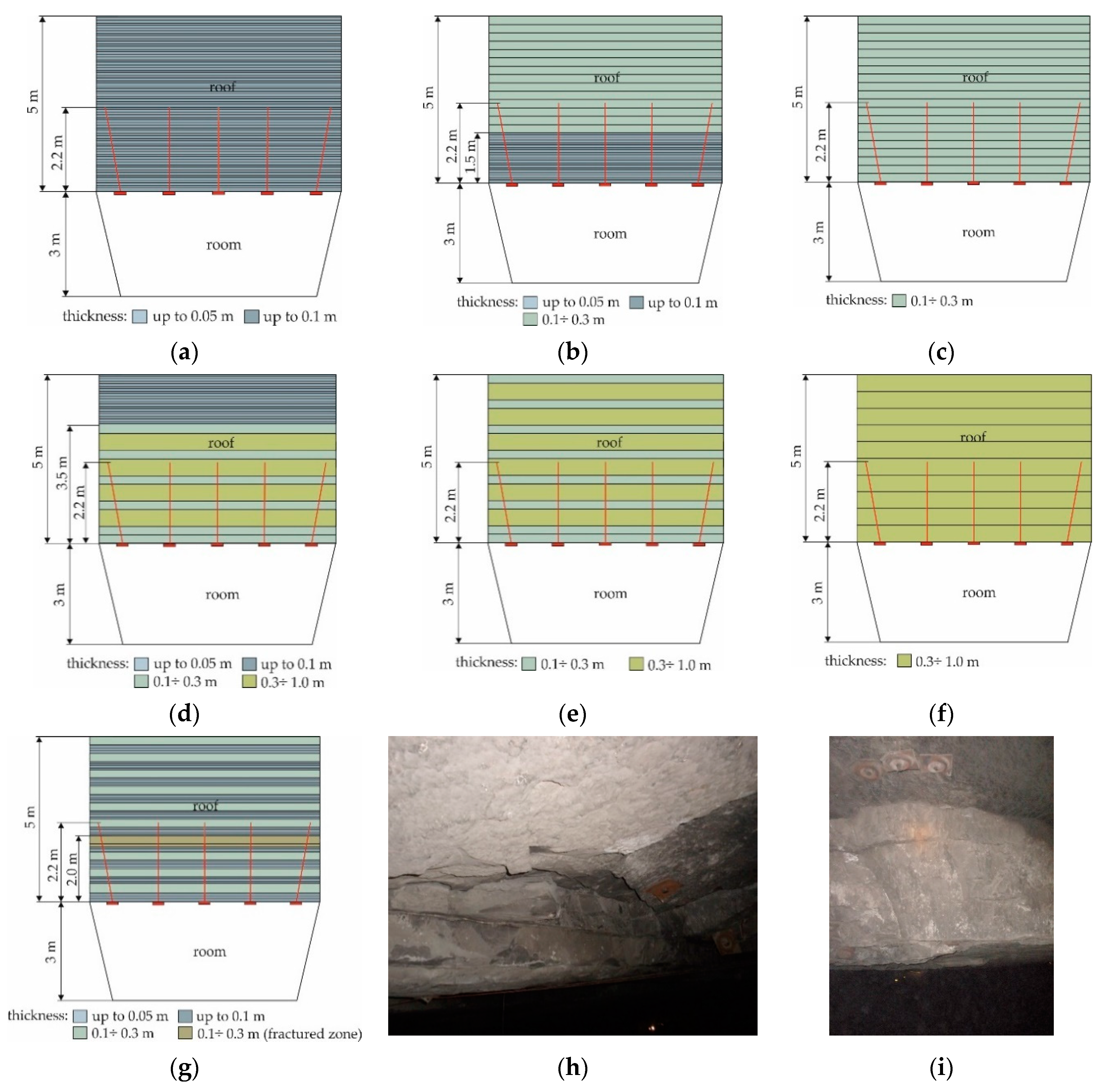
Rock Mass Stratification at Legnica-Głogów Copper District in Poland

Underground mining of copper ore deposits in Poland is carried out in the Legnica-Głogów Copper District (LGOM) in three mining plants: Rudna, Lubin and Polkowice-Sieroszowice. The dominant natural hazard occurring in all three mines is the release of seismic energy in the form of tremors, stress relief and rock bursts [27]. Occurring stress relief in the excavation, according to Polish regulations [28], is defined as a dynamic phenomenon caused by a rock tremor as a result of the part of the excavation that was damaged to the extent of not causing a loss of its serviceability or deterioration of safety conditions. However, as a result of the occurrence of only a seismic event, the excavation does not lose its functionality. The operation of the bolt support under dynamic loads is associated with the work done over time. By comparing the times of arrival of two different groups of seismic waves generated by the tremor, longitudinal and transverse and their impact on the support, it is possible to determine the path that each of these waves travels from the tremor to the point of their registration [29] (Figure 1a–c).
The seismogram presented in Figure 1 is intended to show the duration of the additional dynamic load to which the bolt support is exposed as a result of rock mass vibration and longitudinal and transverse wave propagation. Assuming that the duration of the low-energy dynamic load is several seconds, it is necessary to model the behavior of the bolt support that corresponds to the duration of this phenomenon. One of the ways of reflecting industrial conditions are laboratory tests under static and quasi-static loading, in which the stress-strain characteristics of the rock bolt support are obtained. Knowing the values of the maximum stress and strain, it is possible to select a support with greater flexibility and load-bearing capacity, and to modify the embedded length so as to adapt the bolt support to the conditions of rapidly changing loads. For copper ore deposits in the LGOM region, the mineralization zone has an irregular morphology of the roof and floor, which makes it difficult to adjust the geometry of the mining excavations, and to select such a height of the mining gate that the deposit losses and ore dilution are as low as possible. The contractual area determined on the basis of sampling is considered the border. Mining is carried out in three different lithological types of ore with different physical and chemical properties: carbonates, shales and sandstones. The lithological type of copper ores is the carbonate rocks of the Zechstein limestone. It is noteworthy that carbonate rocks show a stratified structure [30]. In the direct roof there are compact limestone dolomites with numerous anhydrite-calcite veins. Anhydrites with a thickness of about 300 m are deposited directly on the carbonate series. A characteristic feature in the vicinity of the deposit is the presence of layers in the roof with significantly higher strength parameters than in the deposit and in the floor. For example, the compressive strength of roof rocks and overburden is more than two and seven times greater than that of deposit and floor rocks, respectively. The type of stratification (thickness of the layers) depends on the intensity of the geological structures that separate individual layers. In the zones of the bolted roof, the intensity of the occurrence of structures emphasizing stratification is varied. This variability can be observed within one mining field, and even in the vicinity of two excavations [31]. Due to the diversity of the stratification structure of the direct roof, seven characteristic types up to a height of about 5 m were distinguished [32]. In particular, very thin-bed, thin-bed, medium-bed and thick-bed layers with a thickness of 0.05 m were separated, up to 0.1 m, 0.1–0.3 m and 0.3–1 m, respectively (Figure 2a–i).
Taking into account the risk of seismic events and the stratification of the rock mass, laboratory tests were carried out. The purpose of this was to compare the stress-strain characteristics for rock bolts embedded at different lengths under static and quasi-static loading. In the research, a short-term quasi-static load was modeled using the maximum power of a hydraulic pump. In contrast, the static load was performed with hold times, modeling a slow load increase. The obtained test results indicate differences in the maximum stress and strain of the bolt for a short-term load of about 3.2 s compared to static tests.

2. Rock Bolt Testing Procedure under Static and Quasi-Static Loading

The tensile tests for the embedded rock bolts were performed according to two procedures. The static tensile tests consisted of a periodic pressure increase of 10 bar, which was performed with the use of the reduction valve knob located on the control panel (Figure 3a,b). Each increase in pressure was preceded by a holding time, which was 10 s. The test duration until the break was on average 450 s and fell within the scope of both the requirements of the Polish standard [33] regarding tensile tests and the conditions corresponding to the increase in static load in the room excavations. The load was measured using four strain gauge force sensors, while the displacement was monitored with the use of an incremental line encoder. The force sensors were connected to the measuring amplifier in a full-bridge strain gauge configuration, while the encoder was set according to the frequency measurement scheme with the signal with the direction of rotation. In quasi-static tests, a sectional anchorage was used, the same as in the static test. In order to obtain the maximum quasi-static load, the control panel (Figure 3c,d) was set to quasi-static load mode, and on the control panel (Figure 3a,b) the reducing valve was opened for the maximum fluid flow range. During the quasi-static load, stop times were not used. The measuring apparatus and the recording of the results did not change, except for the sampling frequency, which was set at 100 Hz for the quasi-static load, and 10 Hz for the static load. The change in sampling frequency resulted from the short loading time. Rock bolts subjected to a quasi-static load were broken by the application of maximum force in the shortest possible time due to the available pump power. A variable displacement multi-piston pump with constant power and constant pressure regulators was used in the tests. The hydraulic unit was characterized by a 18 kW engine and a maximum supply pressure of 31 MPa [34].
Due to the conditions of the underground copper ore mines of the Legnica-Głogów Copper District, the selection of the rock bolt support was made on the basis of determining the class of the roof. The basic support with lengths of 1.2 m, 1.6 m, 1.8 m, 2.2 m and 2.6 m were considered and, taking into account the stratification of the rock mass (Figure 2), a ribbed steel bolt rod 2.2 m long was selected for the tests. The bolt rod cooperated with a dome washer with a diameter of 150 mm, a height of 25.5 mm and a thickness of 6 mm. The threaded end of the rod was secured with a 34 mm high M20 hexagonal nut. The rock bolt was made of B500SP steel [35]. Detailed characteristics of the rods are presented in Table 1 and in Figure 4a–c.
The interaction of the bolt support with the rock mass was modeled with a concrete mix filled with specially prepared steel cylinders with a diameter of 0.1 m and lengths of 0.05 m, 0.3 m and 0.9 m. The composition of high-performance concrete consists of the following components: crushed aggregate with a rough surface (49%) and a grain size of up to 2 mm; sand (18%) with a grain size of 0.25 mm to 2 mm with the content of dust fraction to a minimum; and water with the superplasticizer Sika VisciCrete-20HE (14%), Portland cement CEM I 42.5R Górażdże with the addition of SikaFume-HR/-TU microsilica (18%). The strength of concrete, made on cubic samples with a side of 150 mm, ranged from 70 to 75 MPa. In the steel cylinders filled with concrete, holes with a diameter of 28 mm were drilled. Manual hammer drills DD130 and TE70-ATC were used for drilling (Figure 5a,b). The drills were equipped with core drills 0.32 m long and a SDS MAX hammer drill bit with a drilling head made of three parts of high-quality tungsten carbide with four cutting blades 0.92 m long. Resin cartridges with a diameter of 24 mm and a length of 0.45 m were used to fix the rods in the holes. The main purpose of the research was to determine the strength parameters for the embedded length ensuring the achievement of full load capacity (Figure 6b–d). According to earlier studies by Skrzypkowski et al. [36], it was found that the minimum embedded length for the bolt rod with a dome washer was 0.2 m. Nevertheless, in addition, in the research it was also decided to study bolt on a very short section of only 0.05 m (Figure 6a,d), which resulted from the very thin-bed structure of the rock mass (Figure 2).

3. Results

Static and quasi-static tensile tests of the partially embedded rock bolts were carried out in the bolting laboratory (Figure 7) at the Department of Mining Engineering and Occupational Safety at AGH University of Science and Technology in Kraków. The aim of the research was to determine the load-displacement characteristics, with the identification of the plastic range, maximum load and displacement (Figure 8), as well as the location of the material continuity interruption. For static and quasi-static studies, the load rate was 0.5 kN/s and 48 kN/s, respectively. This is the maximum value that was obtained with the use of the permissible power of the hydraulic system pump. The test results are presented in Figure 9a–d and in Table 2.
The worst results were obtained for bolts embedded over a distance of 0.05 m. For 10 tests, the bolts slid out of the hole. The loss of adhesion occurred at the contact of the rod with the resin. For both static and quasi-static tests, the maximum load results were very close to each other. The main difference can be seen in the displacement, which for a quasi-static load was more than two times smaller compared to a static load. This is not a complete support characteristic because, as shown in Figure 9b,c, the yield strength is several dozen kilonewtons higher. In the case of the bolts installed at lengths of 0.3 m and 0.9 m, the rock bolt broke in the smallest cross-section of the thread core each time (Figure 10a,b). Despite the fact that for the embedded length of 0.05 m, the bolt support did not work in the full range of the load-displacement characteristics, it is still a clue for further tests. In particular, future research should concern the improvement of the components of the adhesive cartridge: resin, hardener, setting accelerators or retarders. In addition, special attention should be paid to improving the efficiency of mixing the components of the adhesive cartridge in the glove, and their cooperation with both the bolt rod and the surrounding rock. Equally important in future research may be the modification of the bolt rib geometry, in particular their height, inclination, width and spacing along the bolt rod.
For embedded lengths of 0.3 m and 0.9 m, the yield point (F1) under quasi-static load was higher by 4.88% and 3.43%, respectively, compared to the static load. At maximum load (F2), the difference is much greater. Under quasi-static load, the bolt support takes up a greater load by 7.3% and 7.09%, respectively, compared to the static load. In the failure range (F3), also at quasi-static loads, the load value is higher by 4.72% and 2.63%, respectively, in relation to static loads. However, for the length of 0.3 m, the displacements in the elastic range (Δl1), the maximum load (Δl2) the corresponding failure (Δl3), they were about 39.69%, 20.43% and 18.36% higher compared to the quasi-static load, respectively. For the length of 0.9 m, the displacement values (Δl1; Δl2; Δl3) were higher for a static load by 22.54%,15.85% and 18.97%, respectively.

4. Discussion

Based on the load-displacement curves (Figure 9a–c), the stress-strain characteristics were determined (Figure 11a–f). The test results are summarized in Table 3. Additionally, in Figure 12a–f, mean and standard errors for stress and strain are presented. For the lengths of 0.3 m and 0.9 m, the failure occurred each time on the smallest cross-section of the thread core. In the calculation of the tensile stress for the yield stress (σ1) of the maximum stress (σ2) and the failure stress (σ3), the diameter of the thread core was assumed to be 16.45 mm for the calculation of the surface area (A). The value of the tensile stress (σt) was calculated according to formula (1).
σ t = F A
where:
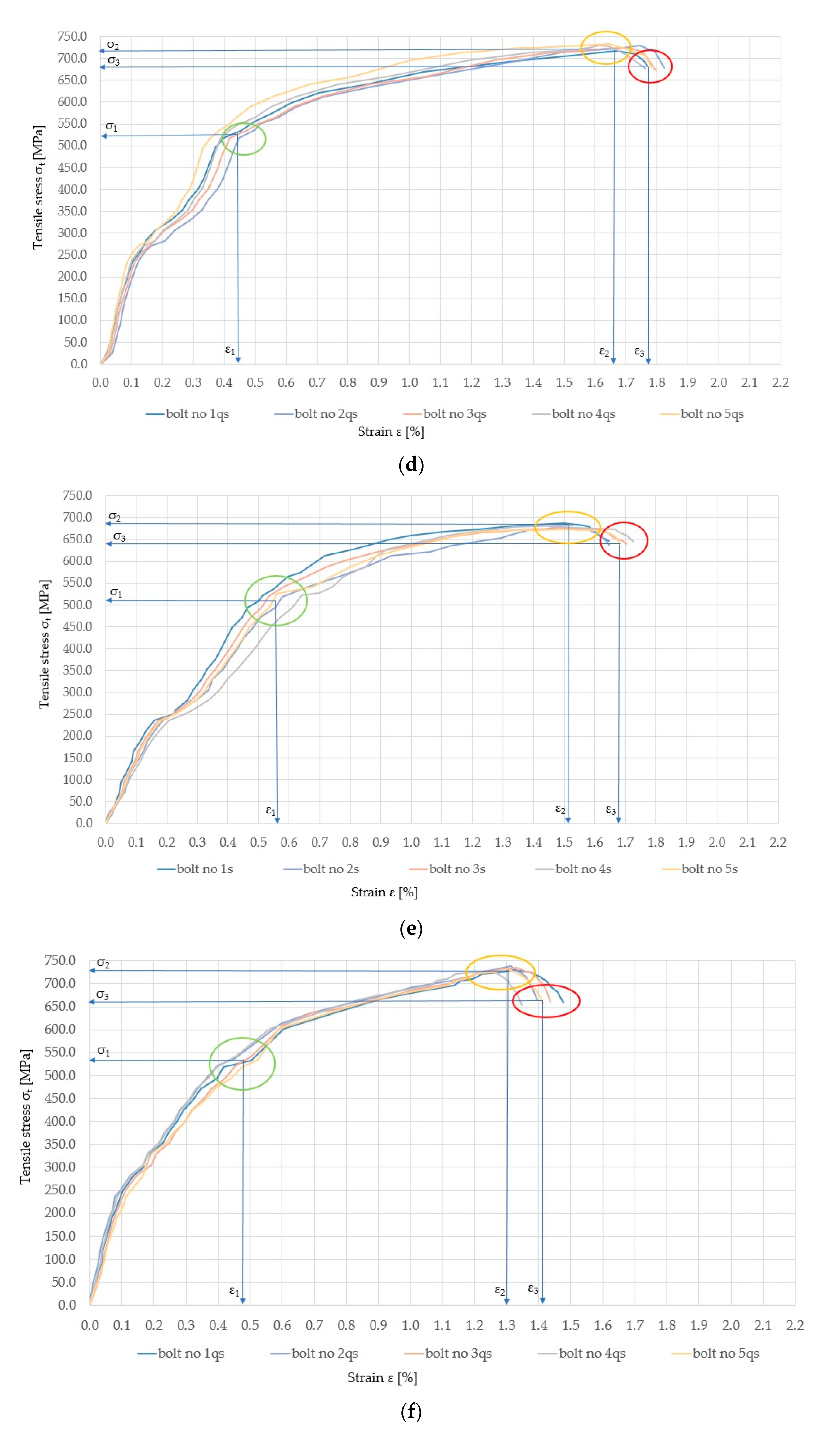
  • σt—tensile stress [MPa],
  • F—applied load [N],
  • A—cross-sectional area [mm2].
The value of specific strain (ε) was calculated according to the formula (2).
ε = l l 0 = l l 0 l 0 · 100 %
where:
  • ε—strain [%],
  • l—length of the bolt rod after strain [mm],
  • l0—initial length of the bolt rod [mm].
One of the most important factors in the performance of a rock bolt is the good adhesion of the ribs to the resin. It enables the correct transfer of the tensile stresses from the resin to the bolt rod, and in the case of higher stresses, it provides a certain slip. For the embedded length of 0.05 m, the rock bolt support worked only in the elastic range. Increasing the length to 0.3 m contributed to the achievement of full stress-strain characteristics. Hoien et al. [37] on the basis of pull-out tests of bolt rods made of steel grade (B500NC with a diameter of 20 mm) fixed in a concrete block on a cement binder at lengths of 0.1 m, 0.15 m, 0.2 m, 0.3 m, 0.45 m and 0.6 m, suggested critical embedment length of a grouted rebar bolt. Authors found two critical embedment related to elastic and plastic steel deformation. Furthermore, they stated that for minimum embedment length equal to 0.3 m, there is a strong relationship between load and water-cement index. Skrzypkowski et al. [36], by testing bolts made of the B500SP steel grade, proved that the minimum embedded length for which the bolt transfers full loads is 0.2 m. Yu et al. [38] modeled the rock mass with a concrete block, in which they installed 3 m long rock bolts fixed at the following lengths: 0.3 m, 0.9 m, 1.35 m, 1.5 m, 1.8 m, 2.1 m, 2.4 m and 2.7 m in order to detect mounting defects. The use of resin cartridges is closely related to the incomplete interaction between the bolt rod, resin and rock mass. The adhesive is surrounded by a glove, which very often causes poor mixing of the components and constitutes a kind of blockage. As a result of improper mixing, numerous sections along the bolt rod may appear that do not fulfill their function, and such embedment can then be considered as multi-point. The described phenomenon requires research in order to determine the minimum embedment length even with a length of at least 0.3 m. Xu et al. [39] tested 2 m long rod bolts which were fitted at lengths of 0.5 m, 1.0 m and 1.5 m with the use of resin cartridges and a setting time ranging from 90 to 180 s. Tests showed that the longer the anchorage length, the greater the load on the bolt rod.

Quasi-Static Coefficient for Stress and Strain

Quasi-static stresses (σqs) can be expressed by the product of the static stress (σs) and the quasi-static coefficient (Cqs), which is a multiplier not less than one, according to the formula (3):
σ qs = C qs · σ s
The values of the quasi-static coefficient for stress (σ1) are: 1.04 and 1.03, respectively, for the lengths of 0.3 m and 0.9 m. For maximum stress (σ2), the ratio of the coefficient was much larger compared to the stress for the yield point (σ1). These are values of 1.07 for both lengths. In the case of failure stress, the difference in the quasi-static coefficient is only 0.018 in favor of the embedment length of 0.3 m. Much greater differences are found in the strain. In order to determine the quasi-static strain (εqs), just like for the stress, it can be expressed by the product of the static strain (εs) and the quasi-static coefficient (Sqs), which is a multiplier not greater than one according to formula (4):
ε qs = S qs · ε s
The values of the quasi-static coefficient for strain (ε1) are 0.72 and 0.85, respectively, for the fixing lengths of 0.3 m and 0.9 m. The strain (ε2) for the maximum stress is equal to 0.86. Also, in the case of the strain (ε3) associated with the failure, the differences are very small, amounting to 0.84 and 0.83 for the fixing lengths of 0.3 m and 0.9 m, respectively. The thread turned out to be the weakest point of the rock bolt. Similar conclusions were obtained by Kang et al. [40] by testing bolts made of steel grades B335, B500 and B700. Within the limits of elasticity of the rock bolt material, a specific value of strain was obtained for a precisely defined tensile stress. These strains appeared immediately after the direct increase in tensile stresses. The research showed that the amount of strain is influenced by the duration of the load. In strictly dynamic studies [41,42] the value of the dynamic coefficient is much higher than the value of 1. Nevertheless, the presented test results under quasi-static loading indicate a slight increase in stress and a reduction in strain.

5. Conclusions

This laboratory study presents a comparison of load-displacement and stress-stress characteristics under static and quasi-static loading. Several conclusions can be drawn:
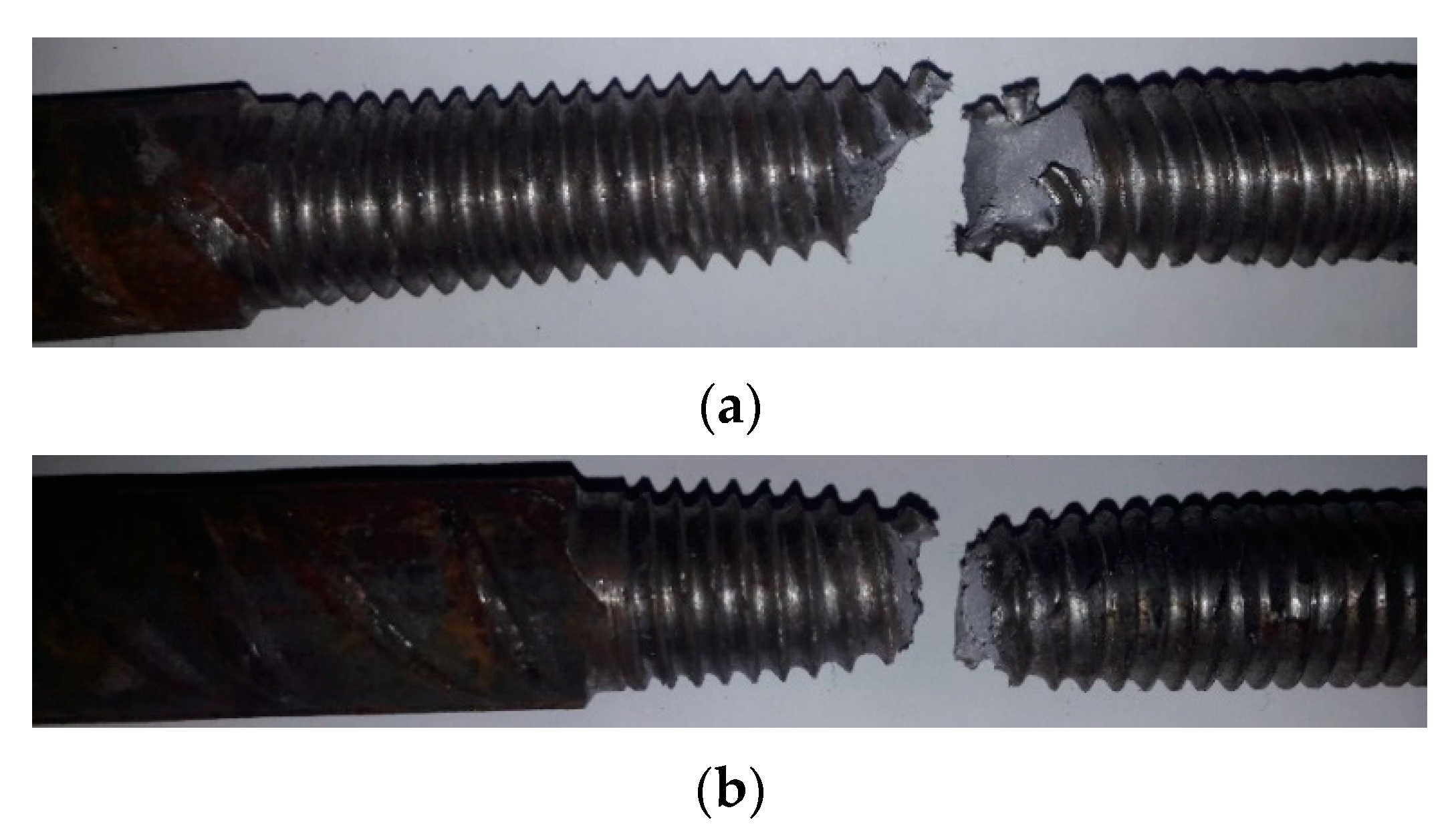
  • The load capacity of a rock bolt with a thread is not determined by the breaking strength of the rod, but by the thread strength;
  • For embedded length of 0.3 m, the tensile stress at the points of yield, maximum and failure for quasi-static stress are higher by 4.92%, 6.94% and 4.48%, respectively, compared to the static stress;
  • For embedded length of 0.9 m, the tensile stress at the points of yield, maximum and failure for quasi-static stress are higher by 3.44%, 7.76% and 2.63%, respectively, compared to the static stress;
  • For embedded length of 0.3 m, the value of strain in the elastic range, the strain at maximum stress and the strain corresponding to failure for quasi-static stress are lower by 27.42%, 13.03% and 15.64%, respectively, compared to the static strain;
  • For embedded length of 0.9 m, the value of strain in the elastic range, the strain at maximum stress and the strain corresponding to failure for quasi-static stress are lower by 14.29%, 13.34% and 16.08%, respectively, compared to the static strain.
The presented research results refer to both static and quick-changing loads occurring in underground mining. As a result of the seismic events, the rock bolt support may be additionally loaded, resulting in a change in the stress and strain state. By modeling the cooperation of the bolt support with the rock mass by using the maximum power of the hydraulic pump, it is possible to reflect to some extent the operating conditions of the bolts at variable loads. Future research should focus on the new construction materials featuring new steel grades, variable rock bolt rod geometry and new adhesive cartridges. The subject of interest will be the determination of the contact between the rock bolt, the resin cartridge and the rock mass model.

Funding

This research was prepared as part of AGH University of Science and Technology in Poland, scientific subsidy under number: 16.16.100.215.

Institutional Review Board Statement

Not applicable.

Informed Consent Statement

Not applicable.

Data Availability Statement

The data presented in this study are new and have not been previously published.

Conflicts of Interest

The author declares no conflict of interest.

References

  1. Waclawik, P.; Snuparek, R.; Kukutsch, R. Rock bolting at the room and pillar method at great depths. Procedia Eng. 2017, 191, 575–582. [Google Scholar] [CrossRef]
  2. Małkowski, P.; Niedbalski, Z. A comprehensive geomechanical method for the assessment of rockburst hazards in underground mining. Int. J. Min. Sci. Technol. 2020, 30, 345–355. [Google Scholar] [CrossRef]
  3. Masoudi, R.; Sharifzadeh, M. Reinforcement selection for deep and high-stress tunnels at preliminary design stages using ground demand and support capacity approach. Int. J. Min. Sci. Technol. 2018, 28, 573–582. [Google Scholar] [CrossRef]
  4. Li, C.C.; Mikula, P.; Simser, B.; Hebblewhite, B.; Joughin, W.; Feng, X.; Xu, N. Discussions on rockburst and dynamic ground support in deep mines. J. Rock Mech. Geotech. Eng. 2019, 11, 1110–1118. [Google Scholar] [CrossRef]
  5. Rahimi, B.; Sharifzadeh, M.; Feng, X.-T. Ground behaviour analysis, support system design and construction strategies in deep hard rock mining e Justified in Western Australian’s mines. J. Rock Mech. Geotech. Eng. 2020, 12, 1–20. [Google Scholar] [CrossRef]
  6. Li, C.C. Principles and methods of rock support for rock burst control. J. Rock Mech. Geotech. Eng. 2020, 12, 1–14. [Google Scholar] [CrossRef]
  7. Kim, H.; Rehman, H.; Ali, W.; Muntaqim Naji, A.; Kim, J.-J.; Kim, J.; Yoo, H. Classification of Factors Affecting the Performance of Fully Grouted Rock Bolts with Empirical Classification Systems. Appl. Sci. 2019, 9, 4781. [Google Scholar] [CrossRef] [Green Version]
  8. Ozturk, C.A.; Dogan, E.; Donmez, M.S.; Karaman, E. Ground Support Design of Underground Openings in Seismically Active Mine: A Case Study from a Lead and Zinc Underground Mine. Geotech. Geol. Eng. 2021, 39, 1–21. [Google Scholar] [CrossRef]
  9. Wang, J.; Apel, D.B.; Pu, Y.; Hall, R.; Wei, C.; Sepehri, M. Numerical modeling for rock bursts: A state-of-the-art review. J. Rock Mech. Geotech. 2020. [Google Scholar] [CrossRef]
  10. Cao, J.; Zhang, N.; Wang, S.; Qiana, D.; Xiea, Z. Physical model test study on support of super pre-stressed anchor in the mining engineering. Eng. Fail. Anal. 2020, 118, 104833. [Google Scholar] [CrossRef]
  11. Feng, X.; Zhang, N.; Lv, C. Effects of Interface Damage Resulting from the Separation of Layered Strata on Bolt Anchoring Systems. Shock. Vib. 2016, 2016, 2590816. [Google Scholar] [CrossRef] [Green Version]
  12. Feng, X.; Zhang, N.; Li, G.; Guo, G. Pullout Test on Fully Grouted Bolt Sheathed by Different Length of Segmented Steel Tubes. Shock. Vib. 2017, 2017, 4304190. [Google Scholar] [CrossRef] [Green Version]
  13. Skrzypkowski, K.; Korzeniowski, W.; Zagórski, K.; Zagórska, A. Flexibility and load-bearing capacity of roof bolting as functions of mounting depth and hole diameter. Energies 2019, 12, 3754. [Google Scholar] [CrossRef] [Green Version]
  14. Bacić, M.; Kovacević, M.S.; Jurić Kaćunić, D. Non-Destructive Evaluation of Rock Bolt Grouting Quality by Analysis of Its Natural Frequencies. Materials 2020, 13, 282. [Google Scholar] [CrossRef] [PubMed] [Green Version]
  15. Zhan, Y.; Li, N.; Wang, H.; Zheng, P.; Zhang, J.; Liu, Q. The Mechanism of Interface Dilatancy of Cement Mortar Rockbolts. Adv. Civ. Eng. 2020, 2020, 8838488. [Google Scholar] [CrossRef]
  16. Zhao, J.-y.; Zhang, D.-s.; Lu, W.-c.; Yang, C.-z. Design and experiment of hydraulic impact loading system for mine cable bolt. Procedia Earth Planet. Sci. 2009, 1, 1337–1342. [Google Scholar] [CrossRef]
  17. He, M.; Gong, W.; Wang, J.; Qi, P.; Tao, Z.; Du, S.; Peng, Y. Development of a novel energy-absorbing bolt with extraordinarily large elongation and constant resistance. Int. J. Rock Mech. Min. Sci. 2014, 67, 29–42. [Google Scholar] [CrossRef]
  18. Zhao, X.; Zhang, S.; Zhu, Q.; Li, H.; Chen, G.; Zhang, P. Dynamic and static analysis of a kind of novel J energy-releasing bolts. Geomat. Nat. Hazards Risk 2020, 11, 2486–2508. [Google Scholar] [CrossRef]
  19. Morozov, M.; Tian, G.Y.; Withers, P.J. The pulsed eddy current response to applied loading of various aluminum alloys. NDT E Int. 2010, 43, 493–500. [Google Scholar] [CrossRef]
  20. Withers, P.J.; Turski, M.; Edwards, L.; Bouchard, P.J.; Buttle, D.J. Recent advances in residual stress measurement. Int. J. Pres. Ves. Pip. 2008, 85, 118–127. [Google Scholar] [CrossRef]
  21. Wilson, J.W.; Tian, G.Y.; Barrans, S. Residual magnetic field sensing for stress measurement. Sens. Actuators A 2007, 135, 381–387. [Google Scholar] [CrossRef]
  22. Skrzypkowski, K.; Korzeniowski, W.; Zagórski, K.; Dominik, I.; Lalik, K. Fast, non-destructive measurement of roof-bolt loads. Stud. Geotech. Mech. 2019, 41, 93–101. [Google Scholar] [CrossRef] [Green Version]
  23. Crompton, B.R.; Sheppard, J. A practical design approach for an improved resin-anchored tendon. J. S. Afr. Inst. Min. Metall. 2020, 120, 7–13. [Google Scholar] [CrossRef] [Green Version]
  24. Feng, X.; Xue, F.; Jiang, W.; Wang, M.; Song, W. Re-think of solving the gloving problem in bolting systems by adulterating steel particles. Constr. Build. Mater. 2021, 268, 121179. [Google Scholar] [CrossRef]
  25. Xu, C.; Li, Z.; Wang, S.; Wang, S.; Fu, L.; Tang, C. Pullout Performances of Grouted Rockbolt Systems with Bond Defects. Rock Mech. Rock Eng. 2018, 51, 861–871. [Google Scholar] [CrossRef]
  26. Campbell, R.; Mould, R.J. Impacts of gloving and un-mixed resin in fully encapsulated roof bolts on geotechnical design assumptions and strata control in coal mines. Int. J. Coal Geol. 2005, 64, 116–125. [Google Scholar] [CrossRef]
  27. Burtan, Z.; Zorychta, A.; Cieślik, J.; Chlebowski, D. Influence of mining operating conditions on fault behavior. Arch. Min. Sci. 2014, 59, 691–704. [Google Scholar] [CrossRef] [Green Version]
  28. Regulation of the Minister of the Environment Regarding Natural Hazards in Mining Plants. Available online: https://sip.lex.pl/akty-prawne/dzu-dziennik-ustaw/zagrozenia-naturalne-w-zakladach-gorniczych-17955795 (accessed on 15 January 2021).
  29. Drzęźla, B.; Dubiński, J.; Fajklewicz, Z.; Goszcz, A.; Marcak, H.; Pilecki, Z.; Zuberek, W. Mining Geophysics Handbook; PAN/AGH Publishing: Kraków, Poland, 1995; Volume II, p. 61. [Google Scholar]
  30. Skrzypkowski, K.; Korzeniowski, W.; Zagórski, K.; Zagórska, A. Adjustment of the Yielding System of Mechanical Rock Bolts for Room and Pillar Mining Method in Stratified Rock Mass. Energies 2020, 13, 2082. [Google Scholar] [CrossRef] [Green Version]
  31. Skrzypkowski, K. Case Studies of Rock Bolt Support Loads and Rock Mass Monitoring for the Room and Pillar Method in the Legnica-Głogów Copper District in Poland. Energies 2020, 13, 2998. [Google Scholar] [CrossRef]
  32. Butra, J.; Dańda, Z.; Katulski, A. The causes of roof rock falls and method control in ore mining. Work Saf. Environ. Prot. Min. 1997, 6, 151–157. [Google Scholar]
  33. Polish Standard: PN-EN 10002-1:2004. In Metallic Materials—Tensile Testing—Part 1: Method of Test at Ambient Temperature; Polish Committee for Standardization: Warszawa, Poland, 2004.
  34. Korzeniowski, W.; Skrzypkowski, K.; Herezy, Ł. Laboratory method for evaluating the characteristics of expansion rock bolts subjected to axial tension. Arch. Min. Sci. 2015, 60, 209–224. [Google Scholar] [CrossRef] [Green Version]
  35. Epstal. Available online: http://epstal.pl/en/reinforcing-steel/properties (accessed on 10 January 2021).
  36. Skrzypkowski, K.; Korzeniowski, W.; Zagórski, K.; Zagórska, A. Modified Rock Bolt Support for Mining Method with Controlled Roof Bending. Energies 2020, 13, 1868. [Google Scholar] [CrossRef] [Green Version]
  37. Hoien, A.H.; Li, C.C.; Zhang, N. Pull-out and Critical Embedment Length of Grouted Rebar Rock Bolts-Mechanisms When Approaching and Reaching the Ultimate Load. Rock Mech. Rock Eng. 2021, 54, 1–18. [Google Scholar] [CrossRef]
  38. Yu, J.-D.; Lee, J.-S. Smart Sensing Using Electromagnetic Waves for Inspection of Defects in Rock Bolts. Sensors 2020, 20, 2821. [Google Scholar] [CrossRef] [PubMed]
  39. Xu, X.; Tian, S. Load transfer mechanism and critical length of anchorage zone for anchor bolt. PLoS ONE 2020, 15, e227539. [Google Scholar] [CrossRef] [PubMed]
  40. Kang, H.; Meng, X. Tests and analysis of mechanical behaviours of rock bolt components for China’s coal mine roadways. J. Rock Mech. Geotech. 2015, 7, 14–26. [Google Scholar] [CrossRef] [Green Version]
  41. Player, J.; Thompson, A.; Villaescusa, E. Dynamic testing of reinforcing system. In Proceedings of the 6th International Symposium on Ground Support in Mining and Civil Engineering Construction, SAIMM, SANIRE and ISRM, Cape Town, South Africa, 30 March–3 April 2008; pp. 597–622. [Google Scholar]
  42. Darlington, B.; Rataj, M.; Roach, W. A new method to evaluate dynamic bolts and the development of a new dynamic rock bolt. In Proceedings of the Ninth International Conference on Deep and High Stress Mining, The Southern African Institute of Mining and Metallurgy, Johannesburg, South Africa, 24–25 June 2019; pp. 205–216. [Google Scholar] [CrossRef] [Green Version]
Figure 1. An exemplary seismogram with the P and S waves: (a) N-S component; (b) the E-W component; (c) Vertical component.
Energies 14 01483 g001
Figure 2. Types of direct roof with stratification structure: (a) Type I; (b) Type II; (c) Type III; (d) Type IV; (e) Type V; (f) Type VI; (g) Type VII; (h) Mid-bed layers; (i) Thick-bed layers.
Energies 14 01483 g002
Figure 3. Load settings on the laboratory stand: (a) Static (pressure reducer); (b) A block diagram of a static setup; (c) Quasi-static; (d) A block diagram of a quasi-static setup.
Energies 14 01483 g003
Figure 4. Bolt rod: (a) Thread; (b) Rebar’s rib 1; (c) Rebar’s rib 2.
Energies 14 01483 g004
Figure 5. Drilling holes with application: (a) Crown drill; (b) Hammer drill bit with SDS MAX mounting.
Energies 14 01483 g005
Figure 6. Bolt rod embedding lengths: (a) 0.05 m; (b) 0.3 m; (c) 0.9 m; (d) Block diagram.
Energies 14 01483 g006
Figure 7. Tensile machine: 1—securing cylinder; 2—extendable discs with an internal blockade for a rod with a washer; 3—four force sensors spaced at 90°; 4—line encoder; 5—block of eight actuators; 6—support frame; 7—hydraulic hoses; 8—steel cylinder with a fixed bolt.
Energies 14 01483 g007
Figure 8. General diagram of the load-displacement characteristic: F1—yield point; F2—maximum load; F3—failure at break; Δl1—displacement in the elastic range; Δl2—displacement for maximum load; Δl3—displacement corresponding to rupture; Er—elastic range; H—hardening; N—neckling; Pr—plastic range.
Energies 14 01483 g008
Figure 9. Load-displacement characteristics under static and quasi-static loading for the fixing length: (a) 0.05 m; (b) 0.3 m; (c) 0.9 m; s—static load; qs—quasi-static load.
Energies 14 01483 g009
Figure 10. Failure on thread under load: (a) Static; (b) Quasi-static.
Energies 14 01483 g010
Figure 11. Stress-strain characteristics for partially embedded rock bolt under load: (a) Static over a distance of 0.05 m; (b) Quasi-static over a distance of 0.05 m; (c) Static over a distance of 0.3 m; (d) Quasi-static over a distance of 0.3 m; (e) Static over a distance of 0.9 m; (f) Quasi-static over a distance of 0.9 m.
Energies 14 01483 g011aEnergies 14 01483 g011b
Figure 12. Mean and standard error for embedded lengths: (a) Stress for 0.05 m; (b); Strain for 0.05 m; (c); Stress for 0.3 m; (d) Strain for 0.3 m; (e) Stress for 0.9 m; (f) Strain for 0.9 m; s—static; qs—quasi-static.
Energies 14 01483 g012
Table 1. Strength and geometrical parameters of the tested rock bolts.
DescriptionValueUnit
characteristic yield point≥500[MPa]
characteristic tensile strength≥575[MPa]
rebar’s rib 1 (measurement on the joint along the rod)22.2[mm]
rebar’s rib 2 (measurement on the rod after turning by 90°)21.2[mm]
the thickness of the weld along the rod3.1[mm]
weld height1.1[mm]
the height of the ribs1.35[mm]
rib width3.6[mm]
distance between ribs parallel oblique26.3[mm]
distance between ribs parallel oblique ribs10.3; 16[mm]
rod length without ribs138.3[mm]
thread length111[mm]
thread diameter19.2[mm]
thread core diameter16.45[mm]
Table 2. Summary of the average tensile values of the rock bolt partially embedded under static and quasi-static load.
ParameterUnitEmbedded Length [m]
0.05 *0.30.9
sqssqssqs
load for the yield point, F1[kN]--108.5113.8110.6114.4
maximum load, F2[kN]62.464.6143.8154.3145.2155.5
load at failure, F3[kN]--137.5144136.4140
displacement in the elastic range, Δl1[mm]--13.769.8512.3410.7
displacement for maximum load, Δl2[mm]8.23.944.236.733.1828.64
displacement corresponding to the failure, Δl3[mm]--46.439.23731.1
* extension from the hole; s—static; qs—quasi-static.
Table 3. Summary of stress and strain results for partially embedded bolt support.
ParameterUnitEmbedded Length [m]
0.05 *0.30.9
sqssqssqs
tensile stress for the yield point, σ1[MPa]--510.78535.92518.78536.67
maximum stress, σ2[MPa]293.8304.3678.84726.48679.31732.04
stress at failure, σ3[MPa]--648.90677.99642.12659.07
strain in the elastic range, ε1[%]--0.620.450.560.48
strain for maximum stress, ε2[%]0.40.21.921.671.501.3
strain corresponding to the failure, ε3[%]--2.111.781.681.41
* extension from the hole; s—static; qs—quasi-static.
Publisher’s Note: MDPI stays neutral with regard to jurisdictional claims in published maps and institutional affiliations.

