Article

Porous Manganese Oxide Networks as High-Capacity and High-Rate Anodes for Lithium-Ion Batteries

Department of Chemical Engineering (BK21 FOUR Graduate Program), Dong-A University, Busan 49315, Korea
*
Author to whom correspondence should be addressed.
Energies 2021, 14(5), 1299; https://doi.org/10.3390/en14051299
Submission received: 5 January 2021 / Revised: 7 February 2021 / Accepted: 20 February 2021 / Published: 26 February 2021
(This article belongs to the Special Issue Advanced Materials and Technologies for Lithium-Ion Battery)

Abstract

:
A mesoporous MnOx network (MMN) structure and MMN/C composites were prepared and evaluated as anodes for high-energy and high-rate lithium-ion batteries (LIB) in comparison to typical manganese oxide nanoparticle (MnNP) and graphite anodes, not only in a half-cell but also in a full-cell configuration (assembled with an NCM523, LiNi0.5Co0.2Mn0.3O2, cathode). With the mesoporous features of the MMN, the MMN/C exhibited a high capacity (approximately 720 mAh g−1 at 100 mA g−1) and an excellent cycling stability at low electrode resistance compared to the MnNP/C composite. The MMN/C composite also showed much greater rate responses than the graphite anode. Owing to the inherent high discharge (de-lithiation) voltage of the MMN/C than graphite as anodes, however, the MMN‖NCM523 full cell showed approximately 87.4% of the specific energy density of the Gr‖NCM523 at 0.2 C. At high current density above 0.2 C, the MMN‖NCM523 cell delivered much higher energy than the Gr‖NCM523 mainly due to the excellent rate capability of the MMN/C anode. Therefore, we have demonstrated that the stabilized and high-capacity MMN/C composite can be successfully employed as anodes in LIB cells for high-rate applications.

Graphical Abstract

1. Introduction

The market volume of lithium-ion batteries (LIBs) is expected to be greater than that of memory semiconductors in the near future owing to their increasing demand in various electrified vehicles and energy storage systems (ESSs) of various scales [1,2,3,4]. Despite the bright future of LIBs, the energy and power density has to be much improved, and costs along the whole battery value chain need to fall to achieve mass market penetration in the future [5]. To increase the energy density of LIBs, high-capacity cathode materials offering high capacity (approximately 200–250 mAh g−1) at high working voltage have been introduced and are expected to be incorporated in commercial cells in the near future [6,7]. Even higher capacity cathode materials such as sulfur (1680 mAh g−1) and Li2S (1210 mAh g−1) are extensively studied in various Li-S battery systems [8,9]. On the contrary, low-capacity graphitic carbon (372 mAh g−1) has been used as the state-of-the-art anode material for almost the last three decades of LIB commercialization in the market. To assemble full battery cells with higher-capacity cathode materials, graphite anodes should be thicker to meet the required capacity ratio (N/P ratio) in the cell. On the thick graphite anodes with sluggish lithium intercalation kinetics, the Li plating is highly likely at high current across the separator owing to the slow Li+ transfer in the electrolyte and increased impedance in the solid phase [10,11], leading to a high possibility of cell short and explosion after long-term use. Therefore, anode materials offering high capacity are urgently demanded. Fast lithium storage kinetics of anode materials are also an important factor for the fast charging capability of LIBs.
Silicon has long been studied as a high-capacity anode material (3570 mA h g−1 for Li15Si4) to replace graphitic carbon anodes for more than the last two decades. Due to many issues associated with its large volume changes (up to 300%), however, its use as a high-capacity anode alone is limited, and only a small amount (~5 wt% mostly as SiOx) has been added to graphite anodes to date to increase cell energy density in some commercial cells [5]. Transition metal oxides (TMOs, such as FeOx and MnOx, etc.) have attracted a great attention because they can store a large amount of lithium by the electrochemical “conversion reaction” shown in equation (1) below [12,13]. Depending on the oxidation number of transition metal in TMOs, they can deliver much higher specific capacity (750–1200 mAh g−1) and have greater gravimetric density than graphite [14,15,16]. The forward reaction (lithiation (charging)), in equation (1), is thermodynamically favored with high negative Gibbs free energy changes, whereas its reverse reaction (de-lithiation (discharging)) requires greater external electromotive force (emf) than the equilibrium potential [12]. Manganese oxides (MnOx) have lower equilibrium potential in the forward reaction and smaller voltage hysteresis between forward and reverse reactions than other TMOs [15,17].
MxOy + 2y (Li+) + 2y (e) ↔ x (M) + y (Li2O)
However, it has been difficult to extract the theoretical capacity of MnOx with stable cycling performance as anodes owing to its low electronic conductivity (~10−7 to ~10−8 S cm−1), large volume changes, and diffusion-induced stresses arising from drastic structural changes during the conversion reaction (1) [18,19,20,21]. Recent studies have shown that the theoretical capacity of MnOx could be obtained with its nano-sized dimension and incorporation with conducting substrates such as carbon [15,22,23]. Previous results indicate that porous and nanostructured MnOx is favored and its carbon composite is desirable to obtain high capacity and long cycle life [17,24,25,26,27,28]. In this study, therefore, we prepared a mesoporous MnOx network (MMN) structure composed of nano-sized primary particles by a solution combustion synthesis. The electrochemical properties of MMN/C composites as anodes were assessed in comparison to those of a typical MnOx nanoparticle (MnNP)/C composite and graphite. In addition to the electrochemical tests in half-cell formats, we investigated the practical electrochemical responses of MMN/C composites as anodes in a full LIB cell assembled with a commercial NCM523 (LiNi0.5Co0.2Mn0.3O2) cathode.

2. Materials and Methods

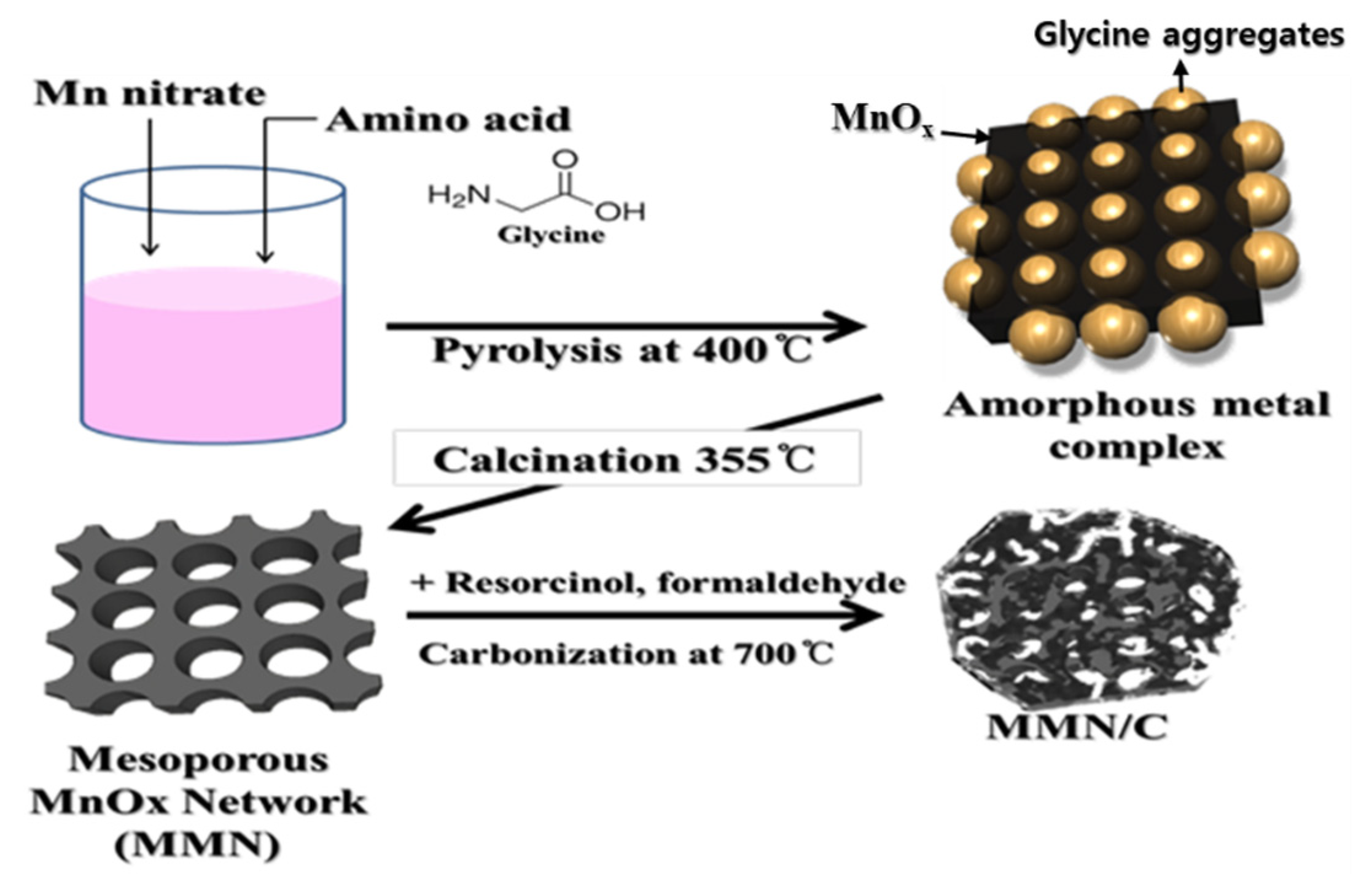
2.1. Synthesis of MMN and MnNPs

The MMN was prepared by a solution combustion synthesis [29] with glycine (98%, Sigma-Aldrich, St. Louis, MO, USA) as an organic template, and manganese nitrate hydrate (Mn(NO3)2xH2O, x = 4–6, 98%, Sigma-Aldrich, St. Louis, MO, USA) as a MnOx precursor (Figure 1). The manganese oxide nanoparticles (MnNPs) were also prepared under the same conditions as the MMN preparation without using an organic template. In a typical synthesis, glycine (1.75 g) and manganese nitrate (1.25 g) were dissolved in deionized (DI) water (10 mL) under sonication. The pink solution in a container was pyrolyzed in a muffle furnace preheated at 400 °C in air for 16 min [29]. The recovered amorphous organo-Mn composite was ground and further calcined by heating up to 355 °C at a ramping rate of 5 °C/min in a muffle furnace for 2 h. During the calcination, organic residue was completely removed to yield the MMN structure. The MnNPs were also obtained by following the same heat treatment processes above for the MMN preparation.

2.2. Preparation of MMN/C and MnNP/C Composites

The MMN/C and MnNP/C composites were prepared by resorcinol–formaldehyde carbon gel coating as a carbon precursor followed by a carbonization process (Figure 1). In a typical preparation, MMN (0.2 g) was dispersed in DI water (18.5 mL) in a vial through sonication. To this dispersion, we added resorcinol (0.08 g), formaldehyde (0.12 g), and 0.5 wt% NH4OH solution (0.002 mL) as a gelation catalyst. The mixture was stirred at room temperature for 30 min, and then subjected to gelation at 80 °C for more than 5 h. The dried composite gel was heated to 700 °C at a ramping rate of 5 °C/min and held at 700 °C for 2 h in a tube furnace under Ar flow to obtain the MMN/C1 composite. MMN/C2 was prepared by following the same procedure as described above for the MMN/C1 but using a smaller amount of resorcinol (0.056 g) and formaldehyde (0.084 g) than for the MMN/C1. The MnNP/C2 composite was obtained by following the same process as for the MMN/C2 composite.

2.3. Material Characterization

The powder X-ray diffraction (XRD) patterns of the samples were obtained using a Rigaku model Miniflex 600 X-ray diffractometer (40 kV, 15 mA, Cu-Kα radiation, λ = 1.5418 Å). The MnOx phase change with synthesis conditions and a carbon coating process was investigated by XRD. The morphology and structure of MnOx and its carbon composite were investigated with transmission electron microscopy (TEM) (JEOL JEM-2010 operated at 200.0 kV, JEOL Ltd., Tokyo, Japan). The electrode thickness changes with the charge and discharge process were measured by scanning electron microscopy (SEM) (JEOL JSM-35CF operated at 10.0 kV, JEOL Ltd., Tokyo, Japan) of electrode cross sections. Brunauer–Emmett–Teller (BET) surface area, pore size, and Barrett−Joyner−Halenda (BJH) pore size distributions of samples were obtained by nitrogen adsorption–desorption isotherms at liquid N2 temperature using a Micromeritics ASAP 2000. The carbon contents in the composites were determined by the weight loss due to carbon oxidation in a thermogravimetric analysis (TGA) run at 800 °C in air flow.

2.4. Electrochemical Measurements

The electrochemical responses of the anodes were measured using CR-2032 coin cells with Li foil as the counter electrodes. The working electrode (27–31 μm thick) was prepared by casting a paste consisting of active material (AM) (MMN, MnNP, MMN/C1, MMN/C2, MnNP/C2, or graphite), carbon black (CB) (conductive additive, Super P Li, TIMCAL Ltd., Bodio, Switzerland), and binder (5 wt% polyvinyl alcohol (PVA) dissolved in DMSO) on Cu foil. The corresponding mass ratio in the paste was 5:4:1 for the AM of the bare MMN or MnNPs, while it was 8:1:1 for the AM of carbon composites or graphite. The mass loadings of active materials were 1.56–1.77 mg/cm2 for graphite, MMN, and MnNPs, while they were 1.92–2.34 for MMN/C1, MMN/C2, and MnNP/C2. For the cathode, a paste consisting of AM (NCM523, a powder sourced from a commercial supplier) (85 wt%), CB (7.5 wt%), and binder (7.5 wt%) (5 wt% polyvinylidene fluoride (PVDF) dissolved in n-methyl-2-pyrrolidone (NMP)) was casted on Al foil. A polypropylene membrane (Celgard 2400) was used as the separator. The electrolyte for the anodes was 1.0 M LiPF6 dissolved in an ethylene carbonate/ethyl methyl carbonate/diethyl carbonate (EC/EMC/DEC) mixture (3:4:3 v/v/v) (PANAX ETECH Ltd., Gongju, Korea). The electrolyte for the cathode was 1.0 M LiPF6 dissolved in ethylene carbonate/dimethyl carbonate (EC/DMC) mixture (3:7 v/v) (PANAX ETECH Ltd., Gongju, Korea). Then, 5 vol% of fluoroethylene carbonate (FEC) was added to the electrolytes to study its effect on the cycling performances of manganese oxide-based anodes. The anode and cathode cells were cycled with the cut-off voltage range of 0.01–3.0 V and 2.6–4.3 V vs. Li/Li+, respectively, on a galvanostat/potentiostat system (WonATech, Korea). The electrochemical impedance spectroscopy (EIS) measurements were obtained using a ZIVE SP2 (WonATech Co., Ltd., Seoul, Korea) analyzer in a frequency range of 100 kHz to 0.01 Hz at an AC amplitude of 10 mV.
Full LIB cells were assembled with the NCM523 cathode (13.6–14.2 mg/cm2) as the working electrode, and graphite (4.9 mg/cm2) and MMN/C2 (3.0 mg/cm2) as the counter electrodes in a CR2032 cell. In order to suppress the rather large first cycle irreversible capacity loss of the anode (MMN/C2) and to match the proper N/P ratio, the full cell was assembled at its charged state by prelithiating the anode down to 0.02 V vs. Li/Li+ at 100 mA g−1 and delithiating the cathode up to 4.3 V vs. Li/Li+ at 0.2 C (1C = 160 mAh g−1) in separate half-cell formats. The electrolyte for the full cell was 1.0 M LiPF6 dissolved in ethylene carbonate/dimethyl carbonate (EC/DMC) mixture (3:7 v/v) (PANAX ETECH Ltd., Gongju, Korea) containing 5.0 vol% of FEC.

3. Results and Discussion

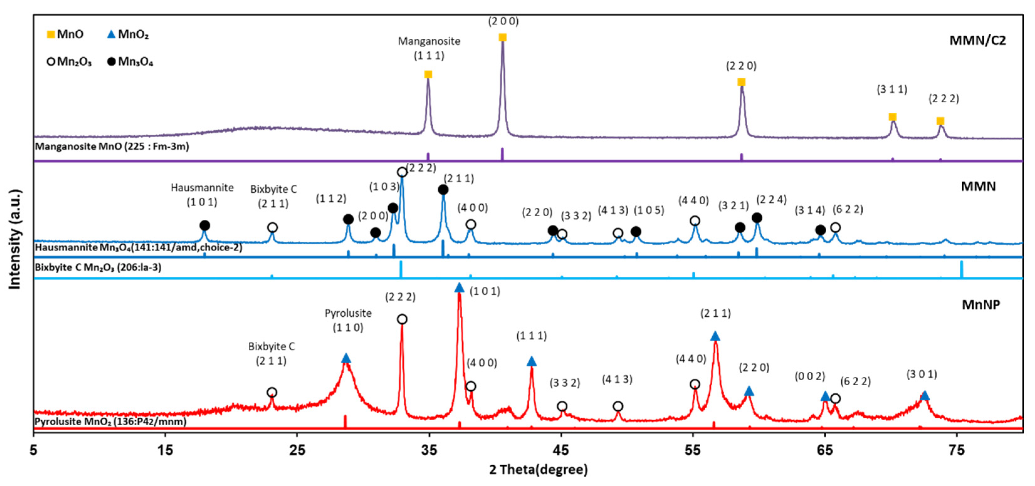
3.1. Properties of Materials

Figure 2 presents the XRD patterns of MnNPs, MMN, and MMN/C composite. The MnNPs prepared without using glycine as the organic template have mixed phases of Mn2O3 (Mn3+) and MnO2 (Mn4+). The MMN contains MnOx species with a lower oxidation state, such as Mn3O4 (Mn(2–3)+) and Mn2O3 (Mn3+) phases, than those in MnNPs owing to the reduction nature of the pyrolysis system with glycine as the organic template [30]. In the MMN/C2 composite, pure MnO phase was formed by further reduction of Mn3O4 and Mn2O3 to MnO (Mn2+) during the carbonization of resorcinol–formaldehyde gel under inert Ar flow. The grain sizes of MnOx particles in MnNPs, MMN, and MMN/C2 were determined to be approximately 10, 12, and 15 nm, respectively, by the Scherrer formula (D = 0.89λ/(β cosθ) [31].
Figure 3 shows the TEM images of MnNPs and the MMN at different magnifications. As shown in Figure 3a,b, the MnNPs prepared without glycine show that separate MnOx nanoparticles of 10–15 nm in diameter are physically aggregated. On the contrary, the TEM images of the MMN in Figure 3c,d reveals that primary MnOx nanoparticles of 10–15 nm in diameter are fused to construct a MnOx network with wide open porous structures. The porous structure of the MMN was further investigated by nitrogen adsorption–desorption measurement. The isotherms in Figure 4a corresponded to a type Ⅳ isotherm, where adsorption increases markedly at high P/P0 due to pore condensation and an adsorption/desorption hysteresis loop is observed, for both MnNPs and the MMN, indicating the existence of mesopores. However, the amount of nitrogen adsorbed was much larger on the MMN than that on MnNPs. As compared in Figure 4b, the MMN has a much larger mesopore volume than MnNPs, which was determined by the BJH method on the desorption branch. As shown in the inset of Figure 4b, the BET surface area (S.A.), total pore volume (Vp), and average pore diameter (Dp) of the MMN were 28.6 m2⋅g−1, 0.20 cc⋅g−1, and 26.1 nm, respectively, which are much greater than those of MnNPs (13.0 m2⋅g−1, 0.06 cc⋅g−1, and 13.9 nm, respectively), indicating a mesoporous nature of the MMN.
The TEM images of MMN/C1 and MMN/C2 composites are shown in Figure S1 (see the Supplementary Materials Section), indicating that all the MnO particles in the composites are conformally covered by carbon layers. The carbon contents in the MMN/C1 and MMN/C2 composites were determined by a TGA run in air flow. In the TGA profiles, weight loss due to desorption of adsorbed water (at <150 °C) and weight gains due to oxidation of MnO (at >280 °C and >430 °C) (see Figure S2) were observed [32]. Hence, the carbon contents in the MMN/C1 and MMN/C2 composites were best estimated to be 15.2 and 11.1 wt%, respectively, by the weight changes between 160 °C and 425 °C, as indicated in the TGA profiles in Figure S2.

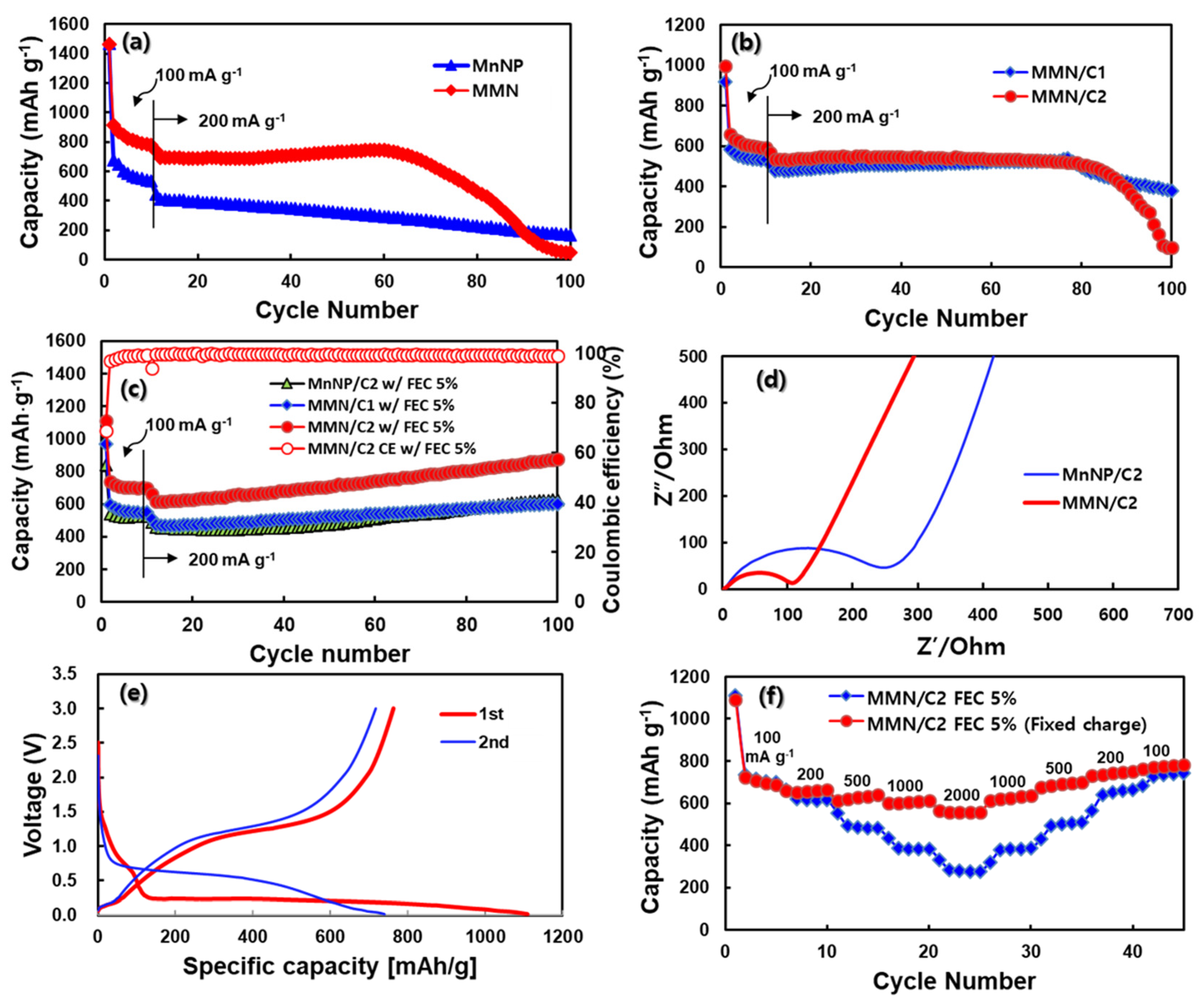
3.2. Electrochemical Properties in a Half-Cell Configuration

To compare the electrochemical responses of bare MnNPs and the MMN first, electrodes were prepared with pastes consisting of AM:CB:binder = 5:4:1 weight ratio, in which carbon black was used in excess because the electrical conductivity of MnOx is very low. The specific capacity in Figure 5a is based on the weight of AM (MnNPs or MMN) only. As compared in Figure 5a, the MMN delivered much higher reversible capacity, which is close to its theoretical one (756 mAh g−1 as MnO + 2Li+ + 2e ↔ Mn + Li2O), than the MnNPs, suggesting the beneficial effect of the mesoporous structure of the MMN. The lithium transport is fast, and most MnOx is wetted with electrolyte and accessible to lithium in the MMN over MnNPs. MnNPs delivered only approximately 74% of the capacity of the MMN at 100 mA g−1. During the extended cycling at 200 mA g−1, MnNPs lost most of their capacity after 100 cycles. On the contrary, the MMN maintained rather high reversible capacity of 692–740 mAh g−1 at 200 mA g−1. However, there is abrupt capacity fading of the MMN after the 60th cycle on, suggesting the cycling stability of the MMN has to be much improved to be used as a high-capacity anode. For this purpose, carbon coating was applied to prepare MMN/C1 and MMN/C2 composites. The electrodes were prepared with a typical paste formulation of AM:CB:binder = 8:1:1 weight ratio. Figure 5b shows the cycling performances of MMN/C1 and MMN/C2, in which the specific capacity is based on the total weight of MMN/C composite. The MMN/C2 delivered reversible capacities of 593–660 mAh g−1 at 100 mA g−1, and 520–535 mAh g−1 at 200 mA g−1, which were higher than those of MMN/C1 with a higher carbon content. With carbon coating, the MMN/C composites exhibited slightly extended cycle life up to 75–80 cycles compared to the simple physical mixture of the MMN and CB in Figure 5a. However, the capacity fading appeared again after approximately 80 cycles at 200 mA g−1 for both MMN/C1 and MMN/C2 composites.
Inspired by the positive results of electrolyte additives, such as fluoroethylene carbonate (FEC) and vinlylene carbonate (VC), which facilitate the formation of a stable solid electrolyte interphase (SEI) layer to improve the cycle life of silicon accompanying large volume changes [33,34], a similar positive effect would be expected with MnOx accompanying drastic structural changes in the conversion reaction (1) above. Hence, a small amount of FEC was added into the electrolyte to improve the cycle life of MMN/C composites. As shown in Figure 5c, both MMN/C1 and MMN/C2 exhibited much improved stable cycling performances. The coulombic efficiency (CE) in the first cycle was 68.8%, increased to 97.0% in the second cycle, and further increased to >99.5% after twelve cycles on. Interestingly, the MnNP/C2 also showed stable cycling performance with FEC. However, the MnNP/C2 delivered much lower capacity (523–530 mAh g−1 at 100 mA g−1) than the MMN/C2 (700–740 mAh g−1 at 100 mA g−1) with approximately the same carbon content in the composites. For all the composites, the capacities gradually increased with cycle number, which is ascribed to the formation of high oxidation state products or gel-like polymeric films due to electrolyte degradation [26,35,36,37]. The EIS data were measured on the fresh MnNP/C2 and MMN/C2 electrodes to obtain the Nyquist plots in Figure 5d. The EIS data were fitted with the equivalent circuit in Figure S3a. The charge transfer resistances (Rct) calculated from the semicircles were 245 and 105 Ω for the MnNP/C2 and MMN/C2, respectively. From the linear Warburg region, the lithium diffusion coefficients (DLi) were estimated to be 3.07 × 10⁻¹⁶ and 1.83 × 10⁻¹⁵ cm2 s−1 for the MnNP/C2 and MMN/C2, respectively, with the DLi being approximately six times higher in MMN/C2 than in MnNP/C2 (see Figure S3 for details). After the first cycle, two distinct semicircles at high- and medium-frequency regions appeared due to the SEI (RSEI) and charge transfer (Rct) resistances, respectively, as shown in the Nyquist plot in Figure S4. The RSEI and Rct values for the MMN/C2 were estimated to be 4.0 and 8.0 Ω, whereas they were 2.5 and 12.5 Ω for the MnNP/C2, respectively. After the initial cycle, the Rct values were reduced significantly compared to those of pristine ones in Figure 5d due to electrochemical activation of electrodes. The electrode cross sections were observed after the first charge for MnNP/C2 and MMN/C2. As shown in Figure S5, the cross section of the MnNP/C2 electrode increased in thickness by as much as 29–53% with highly roughened and swollen morphology after the first charge. On the contrary, the cross section of the MMN/C2 electrode increased in thickness by only approximately 2% with a rather smooth surface morphology. Hence, the porous nature of the MMN enabled the MMN/C2 to outperform the MnNP/C2 with much lower volume expansion and resistance, and faster lithium diffusion rate. However, FEC’s effect on the enhanced cycling stability of MMN/C and MnNP/C deserves further study with sophisticated analyses [38].
Figure 5e displays the charge and discharge voltage profiles of the MMN/C2 in the first two cycles. In the first charge (lithiation) process, a voltage plateau is clearly observed from 1.5–0.8 V vs. Li/Li+ due to FEC decomposition forming an SEI layer on the anode surface [33,34]. A voltage plateau is followed from 0.8–0.25 V vs. Li/Li+ due to the ethyl- and methyl-carbonate decomposition, in accordance with the first charge process of the MMN electrode without FEC in the electrolyte (Figure S6). A long voltage plateau below 0.25 V vs. Li/Li+ is ascribed to the electrochemical conversion reaction, i.e., lithiation of MnOx (Mn3+ and Mn2+) to Mn0 and Li2O, giving the first charge capacity of 1107 mAh g−1 at 100 mA g−1. The first discharge capacity was approximately 763 mAh g−1, giving the first CE of 68.9%. In the second cycle on, the charge voltage increased from 0.25–0.02 to 0.7–0.02 V vs. Li/Li+ due to electrode polarization owing to an abrupt phase transition between polycrystalline MnOx and Mn/Li2O nano-domains [39,40]. The CE increased to 97.0% in the second cycle, and further increased to >99.0% after the 12th cycle on at 200 mA g−1. Figure 5f shows the rate responses of MMN/C2 with FEC (5%) in the electrolyte. The first rate test was conducted by changing the current density (100–2000 mA g−1) for charging and discharging at the same time (filled diamond). The capacities were approximately 735, 659, 501, 382, and 280 mAh g−1 at the current densities of 100, 200, 500, 1000, and 2000 mA g−1, respectively. The MMN/C2 showed a step-wise decrease in capacity with a current increase from 100 to 2000 mA g−1, while the capacity was fully recovered in the decreasing mode of the test, indicating highly reversible electrochemical behavior of the MMN/C2. The other test was conducted by changing the current density for discharging (de-lithiation) only (filled circle) at a fixed charging current density at 100 mA g−1. Even at a high current of 2000 mA g−1, the MMN/C2 still exhibited a high discharge capacity of 557 mAh g−1, indicating its high power capability. For comparison, the same rate tests were conducted with a graphite anode. As shown in Figure S7a, graphite showed very poor capacity retention at a current density above 500 mA g−1, and it lost most of its capacity at ≥1000 mA g−1, when both charging and discharging currents were varied at the same time (filled diamond). Even when charging at a fixed low current density of 100 mA g−1, the discharge capacity of graphite was not much different (filled circle), indicating a very poor rate capability of graphite. Hence, the MMN/C2 with a mesoporous nature and working via electrochemical conversion reaction (1) shows much faster charging/discharging kinetics than graphite working via lithium intercalation/de-intercalation in/out of the d-space between graphene layers. Despite the stabilized cycling performance at high capacity, and the high-rate capability of the MMN/C2 composite, the first CE has to be much improved to a level comparable to that of graphite for its practical application.

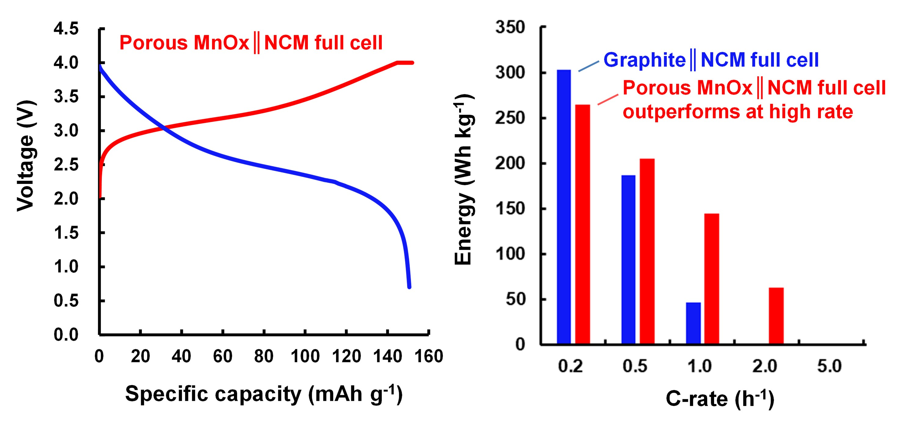
3.3. Electrochemical Properties in a Full-Cell Configuration

Figure 6 displays the electrochemical responses of a full cell of MMN‖NCM523, assembled in a charged state with a pre-lithiated MMN/C2 anode coupled with a commercial NCM523 cathode pre-delithiated as described in the experimental methods. For comparison, a graphite (Gr)‖NCM523 full cell was also assembled in a discharged state without any pre-treatment and tested. Figure 6a,b show typical reversible charge and discharge voltage profiles of Gr‖NCM523 and MMN‖NCM523 full cells at 0.2 C, respectively. The average charge and discharge voltages of the Gr‖NCM523 cell were 3.8 and 3.6 V, whereas those of the MMN‖NCM523 cell were 3.3 and 2.6 V, respectively. Since the discharge voltage of MMN/C2 (approximately 1.2 V vs. Li/Li+), shown in Figure 5e, was much higher than that of graphite (approximately 0.15 V vs. Li/Li+), shown in Figure S7b, in the half-cell test, the MMN‖NCM523 cell exhibited much lower discharge voltage than the Gr‖NCM523 cell by approximately 1.0 V. Similarly, the average charge voltage of the MMN‖NCM523 cell was lower than that of the Gr‖NCM523 cell by approximately 0.5 V. The two full cells exhibited about the same cycling performance at 0.2 C, as compared in Figure 6c. The MMN‖NCM523 cell cycled with FEC in the electrolyte also showed better capacity retention than that without FEC in a prolonged cycling test (Figure S8).
Figure 6d displays the specific energy density of full cells estimated from the discharge process by equation (2) below as a function of the C-rate. At 0.2 C, the energy densities of Gr‖NCM523 and MMN‖NCM523 cells were calculated to be approximately 303 and 265 Wh kg−1, respectively. The MMN‖NCM523 cell exhibited approximately 72.2% of the discharge voltage of the Gr‖NCM523 cell. The MMN‖NCM523 cell, however, showed approximately 87.4% of the energy density of the Gr‖NCM523 cell at 0.2 C owing to the high capacity of the MMN/C2 anode (a smaller amount of electrode material is required) compared to that of graphite. At low current density (0.2 C), MMN/C2, offering a much higher capacity than graphite, could not deliver higher energy density than graphite in a full-cell configuration owing to its high discharge voltage in a half-cell format, leading to a decreased discharge voltage in a full cell. However, at high current density (>0.2 C), the energy densities of the two cells were reversed. For example, the MMN‖NCM523 cell delivered a higher energy level than the Gr‖NCM523 cell at 0.5 C. The difference became even greater at higher current density. At 1.0 C, the MMN‖NCM523 cell delivered 145 Wh kg−1, which was approximately three times greater than that of the Gr‖NCM523 cell (47 Wh kg−1). At 2.0 C, the Gr‖NCM523 cell was not working at all in accordance with the very poor rate responses of graphite (Figure S7a). The corresponding voltage capacity profiles at various C-rates are compared in Figure S9. Overall, we have demonstrated that the stabilized and high-capacity MMN/C composites, having a mesoporous structure composed of small primary particles of MnOx, can be employed as anodes for the replacement of graphite anodes in LIB cells for high-rate applications. The first cycle efficiency of MMN/C, however, has to be much improved for its practical application.
E   = I · 0 t V ( t ) · d t M c a t h o d e + M a n o d e

4. Conclusions

The MMN with a mesoporous structure composed of small primary MnOx nanoparticles was prepared by solution combustion synthesis. The MMN and MMN/C composite delivered much higher capacity as anodes for LIBs than the typical MnNPs and MnNP/C, respectively, indicating the beneficial effect of the mesoporous features of the MMN. It was also found that the addition of FEC (5 wt%) in the electrolyte can improve the cycling stability of all the MnOx/C composites, possibly owing to the formation of stable SEI layers in the early stage, which will be a subject of future study. The MMN/C exhibited much greater rate responses than the state-of-the-art graphite anode in half-cell tests. The stabilized and high-capacity MMN/C (approximately 720 mAh g−1 at 100 mA g−1) anode was evaluated in a full-cell configuration of MMN‖NCM523. Owing to the inherent high discharge voltage of the MMN/C2 anode (approximately 1.2 V vs. Li/Li+), the MMN‖NCM523 exhibited only 87.4% of the energy density of the Gr‖NCM523 cell at a low current of 0.2 C. At a high current density above 0.2 C, however, the MMN‖NCM523 delivered much higher energy than the Gr‖NCM523 cell, suggesting that the MMN/C composite can be successfully employed as anodes for the replacement of graphite anodes in LIB cells for high-rate applications.

Supplementary Materials

The following are available online at https://www.mdpi.com/1996-1073/14/5/1299/s1, Figure S1: TEM images of MMN/C1 (a,b) and MMN/C2 (c,d). Figure S2: (a) TGA profiles of MMN/C1 and MMN/C2, (b) proposed oxidation of MnO in air [32]. Figure S3: Details for Warburg factors and lithium diffusion coefficients. Figure S4: Nyquist plots of NnNP/C2 and MMN/C2 after cycle. Figure S5: SEM images of electrode cross sections before and after lithiation, Figure S6: Charge and discharge voltage profiles of MMN for the first cycle without FEC (5%). Figure S7: (a) Rate responses and (b) charge and discharge voltage profiles of graphite. Figure S8: Cycling performances of MMN‖NCM523 full cells cycled with and without FEC. Figure S9: Voltage-capacity profiles of (a) Gr‖NCM523 and (b) MMN‖NCM523 full cells at various C-rates.

Author Contributions

Conceptualization, material synthesis, characterizations and electrochemical measurements, and writing—original draft preparation, J.C.; methodology, investigation, and resources, W.J.B.; investigation, data collection, and analysis, D.K.; conceptualization, writing—review and editing, supervision, and funding acquisition, J.K.L. All authors have read and agreed to the published version of the manuscript.

Funding

This research was supported by the National Research Foundation of Korea Grant funded by the Ministry of Science and ICT (NRF-2020R1A2B5B01001651).

Institutional Review Board Statement

Not applicable.

Informed Consent Statement

Not applicable.

Data Availability Statement

Not applicable.

Acknowledgments

We would like to acknowledge the research fund by the NRF of Korea for this study (NRF-2020R1A2B5B01001651).

Conflicts of Interest

The authors declare no conflict of interest.

References

  1. Thackeray, M.M.; Wolverton, C.; Isaacs, E.D. Electrical energy storage for transportation-approaching the limits of, and going beyond, lithium-ion batteries. Energy Environ. Sci. 2012, 5, 7854–7863. [Google Scholar] [CrossRef]
  2. Scrosati, B.; Garche, J. Lithium batteries: Status, prospects and future. J. Power Sources 2010, 195, 2419–2430. [Google Scholar] [CrossRef]
  3. Tarascon, J.M. Key challenges in future Li-battery research. Philos. Trans. R. Soc. A Math. Phys. Eng. Sci. 2010, 368, 3227–3241. [Google Scholar] [CrossRef] [PubMed] [Green Version]
  4. Whittingham, M.S. Materials Challenges Facing Electrical Energy Storage. MRS Bull. 2008, 33, 411–419. [Google Scholar] [CrossRef] [Green Version]
  5. Schmuch, R.; Wagner, R.; Horpel, G.; Placke, T.; Winter, M. Performance and cost of materials for lithium-based rechargeable automotive batteries. Nat. Energy 2018, 3, 267–278. [Google Scholar] [CrossRef]
  6. Sun, Y.K.; Chen, Z.H.; Noh, H.J.; Lee, D.J.; Jung, H.G.; Ren, Y.; Wang, S.; Yoon, C.S.; Myung, S.T.; Amine, K. Nanostructured high-energy cathode materials for advanced lithium batteries. Nat. Mater. 2012, 11, 942–947. [Google Scholar] [CrossRef] [PubMed]
  7. Manthiram, A.; Knight, J.C.; Myung, S.T.; Oh, S.M.; Sun, Y.K. Nickel-Rich and Lithium-Rich Layered Oxide Cathodes: Progress and Perspectives. Adv. Energy Mater. 2016, 6, 23. [Google Scholar] [CrossRef]
  8. Bruce, P.G.; Hardwick, S.A.F.L.J.; Tarascon, J.M. Li–O2 and Li–S batteries with high energy storage. Nat. Mater. 2012, 11, 19–29. [Google Scholar] [CrossRef] [PubMed]
  9. Manthiram, A.; Chung, S.H.; Zu, C.X. Lithium-Sulfur Batteries: Progress and Prospects. Adv. Mater. 2015, 27, 1980–2006. [Google Scholar] [CrossRef]
  10. Singh, M.; Kaiser, J.; Hahn, H. Thick Electrodes for High Energy Lithium Ion Batteries. J. Electrochem. Soc. 2015, 162, A1196–A1201. [Google Scholar] [CrossRef]
  11. Finegan, D.P.; Quinn, A.; Wragg, D.S.; Colclasure, A.M.; Lu, X.K.; Tan, C.; Heenan, T.M.M.; Jervis, R.; Brett, D.J.L.; Das, S.; et al. Spatial dynamics of lithiation and lithium plating during high-rate operation of graphite electrodes. Energy Environ. Sci. 2020, 13, 2570–2584. [Google Scholar] [CrossRef]
  12. Poizot, P.; Laruelle, S.; Grugeon, S.; Tarascon, J.M. Rationalization of the Low-Potential Reactivity of 3d-Metal-Based Inorganic Compounds toward Li. J. Electrochem. Soc. 2002, 149, A1212. [Google Scholar] [CrossRef]
  13. Yoon, T.; Kim, J.; Lee, J.K. Electrostatic Self-Assembly of Fe3O4 Nanoparticles on Graphene Oxides for High Capacity Lithium-Ion Battery Anodes. Energies 2013, 6, 4830–4840. [Google Scholar] [CrossRef]
  14. Yoon, T.; Chae, C.; Sun, Y.-K.; Zhao, X.; Kung, H.H.; Lee, J.K. Bottom-up in situ formation of Fe3O4 nanocrystals in a porous carbon foam for lithium-ion battery anodes. J. Mater. Chem. 2011, 21, 17325. [Google Scholar] [CrossRef]
  15. Chae, C.; Kim, J.H.; Kim, J.M.; Sun, Y.K.; Lee, J.K. Highly reversible conversion-capacity of MnOx-loaded ordered mesoporous carbon nanorods for lithium-ion battery anodes. J. Mater. Chem. 2012, 22, 17870–17877. [Google Scholar] [CrossRef]
  16. Yeom, D.H.; Choi, J.; Byun, W.J.; Lee, J.K. Manganese oxides nanocrystals supported on mesoporous carbon microspheres for energy storage application. Korean J. Chem. Eng. 2016, 33, 3029–3034. [Google Scholar] [CrossRef]
  17. Gu, X.; Yue, J.; Li, L.J.; Xue, H.T.; Yang, J.; Zhao, X.B. General Synthesis of MnOx (MnO2, Mn2O3, Mn3O4, MnO) Hierarchical Microspheres as Lithium-ion Battery Anodes. Electrochim. Acta 2015, 184, 250–256. [Google Scholar] [CrossRef]
  18. Pasero, D.; Reeves, N.; West, A.R. Co-doped Mn3O4: A possible anode material for lithium batteries. J. Power Sources 2005, 141, 156–158. [Google Scholar] [CrossRef]
  19. He, Y.; Huang, L.; Cai, J.-S.; Zheng, X.-M.; Sun, S.-G. Structure and electrochemical performance of nanostructured Fe3O4/carbon nanotube composites as anodes for lithium ion batteries. Electrochim. Acta 2010, 55, 1140–1144. [Google Scholar] [CrossRef]
  20. Klose, P.H. Electrical Properties of Manganese Dioxide and Manganese Sesquioxide. J. Electrochem. Soc. 1970, 117, 854. [Google Scholar] [CrossRef]
  21. Zhou, W.B. Effects of external mechanical loading on stress generation during lithiation in Li-ion battery electrodes. Electrochim. Acta 2015, 185, 28–33. [Google Scholar] [CrossRef] [Green Version]
  22. Wang, H.; Cui, L.-F.; Yang, Y.; Casalongue, H.S.; Robinson, J.T.; Liang, Y.; Cui, Y.; Dai, H. Mn3O4-Graphene Hybrid as a High-Capacity Anode Material for Lithium Ion Batteries. J. Am. Chem. Soc. 2010, 132, 13978–13980. [Google Scholar] [CrossRef] [Green Version]
  23. Deng, Y.F.; Wan, L.N.; Xie, Y.; Qin, X.S.; Chen, G.H. Recent advances in Mn-based oxides as anode materials for lithium ion batteries. RSC Adv. 2014, 4, 23914–23935. [Google Scholar] [CrossRef]
  24. Gao, J.; Lowe, M.A.; Abruña, H.C.D. Spongelike Nanosized Mn3O4as a High-Capacity Anode Material for Rechargeable Lithium Batteries. Chem. Mat. 2011, 23, 3223–3227. [Google Scholar] [CrossRef]
  25. Zhong, K.; Zhang, B.; Luo, S.; Wen, W.; Li, H.; Huang, X.; Chen, L. Investigation on porous MnO microsphere anode for lithium ion batteries. J. Power Sources 2011, 196, 6802–6808. [Google Scholar] [CrossRef]
  26. Li, X.W.; Li, D.; Qiao, L.; Wang, X.H.; Sun, X.L.; Wang, P.; He, D.Y. Interconnected porous MnO nanoflakes for high-performance lithium ion battery anodes. J. Mater. Chem. 2012, 22, 9189–9194. [Google Scholar] [CrossRef]
  27. Wang, Y.-T.; Lu, A.-H.; Li, W.-C. Mesoporous manganese dioxide prepared under acidic conditions as high performance electrode material for hybrid supercapacitors. Microporous Mesoporous Mater. 2012, 153, 247–253. [Google Scholar] [CrossRef]
  28. Liu, H.Q.; Cao, K.Z.; Li, W.Y.; Han, Q.Q.; Zheng, R.T.; Shu, J.; Zhang, Z.; Huang, K.J.; Jing, Q.S.; Jiao, L.F. Constructing hierarchical MnO2/Co3O4 heterostructure hollow spheres for high-performance Li-Ion batteries. J. Power Sources 2019, 437, 8. [Google Scholar] [CrossRef]
  29. Wen, W.; Wu, J.-M.; Cao, M.-H. Facile synthesis of a mesoporous Co3O4 network for Li-storage via thermal decomposition of an amorphous metal complex. Nanoscale 2014, 6, 12476–12481. [Google Scholar] [CrossRef] [PubMed]
  30. Acedera, R.A.E.; Gupta, G.; Mamlouk, M.; Balela, M.D.L. Solution combustion synthesis of porous Co3O4 nanoparticles as oxygen evolution reaction (OER) electrocatalysts in alkaline medium. J. Alloy Compd. 2020, 836, 13. [Google Scholar] [CrossRef]
  31. Chae, C.; Park, H.; Kim, D.; Kim, J.; Oh, E.S.; Lee, J.K. A Li-ion battery using LiMn2O4 cathode and MnOx/C anode. J. Power Sources 2013, 244, 214–221. [Google Scholar] [CrossRef]
  32. Augustin, M.; Fenske, D.; Bardenhagen, I.; Westphal, A.; Knipper, M.; Plaggenborg, T.; Kolny-Olesiak, J.; Parisi, J. Manganese oxide phases and morphologies: A study on calcination temperature and atmospheric dependence. Beilstein J. Nanotechnol. 2015, 6, 47–59. [Google Scholar] [CrossRef] [PubMed]
  33. Xu, C.; Lindgren, F.; Philippe, B.; Gorgoi, M.; Bjorefors, F.; Edstrom, K.; Gustafsson, T. Improved Performance of the Silicon Anode for Li-Ion Batteries: Understanding the Surface Modification Mechanism of Fluoroethylene Carbonate as an Effective Electrolyte Additive. Chem. Mater. 2015, 27, 2591–2599. [Google Scholar] [CrossRef]
  34. Jaumann, T.; Balach, J.; Langklotz, U.; Sauchuk, V.; Fritsch, M.; Michaelis, A.; Teltevskij, V.; Mikhailova, D.; Oswald, S.; Klose, M.; et al. Lifetime vs. rate capability: Understanding the role of FEC and VC in high-energy Li-ion batteries with nano-silicon anodes. Energy Storage Mater. 2017, 6, 26–35. [Google Scholar] [CrossRef]
  35. Zhong, K.F.; Xia, X.; Zhang, B.; Li, H.; Wang, Z.X.; Chen, L.Q. MnO powder as anode active materials for lithium ion batteries. J. Power Sources 2010, 195, 3300–3308. [Google Scholar] [CrossRef]
  36. Zhou, G.M.; Wang, D.W.; Li, F.; Zhang, L.L.; Li, N.; Wu, Z.S.; Wen, L.; Lu, G.Q.; Cheng, H.M. Graphene-Wrapped Fe3O4 Anode Material with Improved Reversible Capacity and Cyclic Stability for Lithium Ion Batteries. Chem. Mater. 2010, 22, 5306–5313. [Google Scholar] [CrossRef]
  37. Xu, G.L.; Xu, Y.F.; Sun, H.; Fu, F.; Zheng, X.M.; Huang, L.; Li, J.T.; Yang, S.H.; Sun, S.G. Facile synthesis of porous MnO/C nanotubes as a high capacity anode material for lithium ion batteries. Chem. Commun. 2012, 48, 8502–8504. [Google Scholar] [CrossRef]
  38. Zhang, X.Q.; Cheng, X.B.; Chen, X.; Yan, C.; Zhang, Q. Fluoroethylene Carbonate Additives to Render Uniform Li Deposits in Lithium Metal Batteries. Adv. Funct. Mater. 2017, 27, 8. [Google Scholar] [CrossRef]
  39. Sun, B.; Chen, Z.; Kim, H.-S.; Ahn, H.; Wang, G. MnO/C core–shell nanorods as high capacity anode materials for lithium-ion batteries. J. Power Sources 2011, 196, 3346–3349. [Google Scholar] [CrossRef]
  40. Park, H.; Yeom, D.H.; Kim, J.; Lee, J.K. MnO/C nanocomposite prepared by one-pot hydrothermal reaction for high performance lithium-ion battery anodes. Korean J. Chem. Eng. 2015, 32, 178–183. [Google Scholar] [CrossRef]
Figure 1. Schematic illustration for the synthesis of MMN and MMN/C composite.
Energies 14 01299 g001
Figure 2. XRD patterns of manganese oxide nanoparticles (MnNPs), MMN, and MMN/C2 composite.
Energies 14 01299 g002
Figure 3. TEM images of (a) MnNPs, (b) MnNPs at high magnification, (c) MMN, and (d) MMN at high magnification.
Energies 14 01299 g003
Figure 4. (a) Nitrogen adsorption–desorption isotherms, and (b) Barrett−Joyner−Halenda (BJH) pore size distributions of MMN and MnNPs (inset shows the surface area (S.A.), total pore volume (Vp), and average pore diameter (Dp) of MMN and MnNPs).
Energies 14 01299 g004
Figure 5. Cycling performances of (a) MnNPs and MMN with electrode formulation of AM:carbon black (CB):binder = 5:4:1, (b) MMN/C1 and MMN/C2, and (c) MnNP/C2, MMN/C1, and MMN/C2 with FEC (5%) containing electrolyte, (d) Nyquist plots of MnNP/C2 and MMN/C2, (e) charge and discharge voltage profiles of MMN/C2 for the initial two cycles, and (f) rate responses of MMN/C2 with current density changes for both charging and discharging processes at the same time (filled diamond) or for discharging process only at fixed charging current (100 mA g−1) (filled circle).
Energies 14 01299 g005
Figure 6. Reversible charge and discharge voltage profiles of (a) Gr‖NCM523 and (b) MMN‖NCM523 full cells at 0.2C, (c) cycling performances of Gr‖NCM523 and MMN‖NCM523 full cells at 0.2C, and (d) specific energy density of Gr‖NCM523 and MMN‖NCM523 full cells as a function of C-rate.
Energies 14 01299 g006
Publisher’s Note: MDPI stays neutral with regard to jurisdictional claims in published maps and institutional affiliations.

