Review

Progress in Material Development for Low-Temperature Solid Oxide Fuel Cells: A Review

by
Mohsen Fallah Vostakola
1 and
Bahman Amini Horri
2,*
1
School of Metallurgy and Materials Engineering, Iran University of Science and Technology (IUST), Narmak, 16846-13114 Tehran, Iran
2
Department of Chemical and Process Engineering, Faculty of Engineering & Physical Sciences, University of Surrey, Guildford, Surrey GU2 7XH, UK
*
Author to whom correspondence should be addressed.
Energies 2021, 14(5), 1280; https://doi.org/10.3390/en14051280
Submission received: 6 January 2021 / Revised: 19 February 2021 / Accepted: 22 February 2021 / Published: 26 February 2021

Abstract

:
Solid oxide fuel cells (SOFCs) have been considered as promising candidates to tackle the need for sustainable and efficient energy conversion devices. However, the current operating temperature of SOFCs poses critical challenges relating to the costs of fabrication and materials selection. To overcome these issues, many attempts have been made by the SOFC research and manufacturing communities for lowering the operating temperature to intermediate ranges (600–800 °C) and even lower temperatures (below 600 °C). Despite the interesting success and technical advantages obtained with the low-temperature SOFC, on the other hand, the cell operation at low temperature could noticeably increase the electrolyte ohmic loss and the polarization losses of the electrode that cause a decrease in the overall cell performance and energy conversion efficiency. In addition, the electrolyte ionic conductivity exponentially decreases with a decrease in operating temperature based on the Arrhenius conduction equation for semiconductors. To address these challenges, a variety of materials and fabrication methods have been developed in the past few years which are the subject of this critical review. Therefore, this paper focuses on the recent advances in the development of new low-temperature SOFCs materials, especially low-temperature electrolytes and electrodes with improved electrochemical properties, as well as summarizing the matching current collectors and sealants for the low-temperature region. Different strategies for improving the cell efficiency, the impact of operating variables on the performance of SOFCs, and the available choice of stack designs, as well as the costing factors, operational limits, and performance prospects, have been briefly summarized in this work.

1. Introduction

Deploying more efficient and robust power conversion devices to supply affordable energy with reduced CO2 emission becomes one of the biggest global challenges in this century. Today, more than 70% of the global energy demand for power generation, transportation, and industrial heating comes from fossil fuels extracted from deep within the Earth’s crust. However, harnessing energy from fossil fuels is associated with two major drawbacks: first, due to the scarcity and exhaustible nature of these fuels, they may fail to satisfy the increasing rate of energy demand in the close future; and second, those fuels eventually lead to an increase in the atmospheric concentrations of greenhouse gases (GHGs) which consequently cause a noticeable change in the climate patterns with a contribution to acid rains, water pollution, air pollution, global warming, etc. [1,2,3,4,5,6]. Thus, a comprehensive and urgent solution shall be developed to tackle both the energy and environmental challenges based on the renewable energy sources (such as solar, wind, hydroelectric power, etc.), along with the application of more sustainable energy conversion devices. Nowadays, there is a growing interest in developing fuel cells for both portable and stationary power applications because of their high efficiency, environmental-friendly operation, and fuel flexibility [7,8,9,10]. A fuel cell is an electrochemical device that can directly convert the chemical energy of fuels into electricity through a more reversible operation. The first fuel cell, so-called "the gas voltaic battery", was invented by Sir William Grove in 1839, which could generate electricity by combining hydrogen and oxygen gases [7,11]. Offering a relatively higher efficiency (65–85%) and fewer emissions compared to the internal-combustion engines (Carnot cycle, with an efficiency below 45% [12]), fuel cell technology is considered as one of the most promising candidates for replacing the conventional power generation systems [7,8,9,10].
Fuel cells are structurally comprised of an electrolyte layer sandwiched between a couple of porous electrodes. The electrolyte layer has an essential role, as the heart of fuel cell, for indicating the cell operating temperature range, the type of the electrochemical reactions taking place at the electrodes, and the type of catalytic constituents of the electrodes. Thus, fuel cells are classified based on the type of their electrolyte material into various categories such as alkaline fuel cell (AFC) [13], direct methanol fuel cell (DMFC) [14], molten carbonate fuel cell (MCFC) [15], proton exchange membrane fuel cell (PEMFC) [16], phosphoric acid fuel cell (PAFC) [13], solid oxide fuel cell (SOFC) [17], and so on. Among the different types of fuel cells, solid oxide fuel cells have attracted great interests because of their unique properties such as offering comparably a higher efficiency, extensive fuel flexibility, more durability, and relatively lower cost of fabrication because of their capability to operate with non-precious metals [8,14,18,19,20,21,22]. SOFCs have a wide range of applications including combined heat and power (CHP) systems, stationary and portable power plants, hybrid vehicles, distributed power sources, etc. [1,20,23,24]. Despite the numerous advantages of SOFC, however, their relatively slower start-up, thermochemical instability of the cell individual layers, and the high-temperature range required for exhibiting adequate ionic activity have been addressed to be their major drawbacks [3,8,24,25,26].

1.1. Structure of SOFCs

1.1.1. SOFC Individual Layers

Each SOFC consists of three main components, namely, anode, electrolyte, and cathode, along with an interconnect layer integrated as the current collector on top of each electrode. The SOFC single cells should provide high electrochemical performance, acceptable thermochemical stability, and adequate fuel efficiency during the high-temperature red-ox (reduction-oxidation) cycles of operation. Both electrodes should be fabricated with a certain extent of microstructural porosity to allow forming the interfacial areas at the junction of electrolyte, electrode, and the microstructural pores, so-called triple-phase boundary (TPB). The TPBs are believed to be the active sites supporting the electrochemical reactions in the SOFC structure. In SOFCs, the electrochemical oxidation of fuels takes place at the anode TPBs. The SOFC anode layer should possess a fine grain size distribution, suitable porosity, sufficient electrical conductivity, desirable chemical and thermal compatibility, high electrocatalytic activity, acceptable mechanical strength, and a matching thermal expansion coefficient (TEC) with the other cell components. The following steps should take place in order to successfully achieve the electrochemical oxidation of fuels in the SOFC anode layers [27,28]:
  • Transportation of fuel molecules into the porous structure of anode and their adsorption onto the anode surface.
  • Diffusion of adsorbed fuel species to the TPBs and simultaneously, desorption of the product of electro-catalytically species from the anode surface.
  • Transportation of oxide ions (O2−) across the electrolyte, followed by diffusion of them to the TPBs.
  • Releasing the electrons from the charged species into the bulk of the anode electrocatalytic constituents at the TPB.
  • Extension of active TPBs, which are well-interconnected to the available ionic-electronic conduction paths and mass-transfer channels at the SOFC anode structure.
Generally, the electrical conductivity of anode material should be at least 100 S·m−1 at the operating temperature [27]. The SOFC anode materials should consist of both the ionic- and electronic constituents so-called cermet (ceramic–metal) composites. Nickel/Yttria-stabilized zirconia (Ni-YSZ) is one of the most common anode cermets reported to have an acceptable electrical conductivity in the range of 102–104 S·m−1 for high-temperature SOFCs. In addition to the fact that the SOFC anode cermets encompass a suitable amount of porosity which can accelerate fuel diffusion, they also facilitate oxygen ions migration through the active sites of the anode. In the case of using hydrogen ( H 2 ) and/or methane ( CH 4 ) as the fuel, the possible half-cell reactions of the SOFC anode could be written as follows [29,30,31,32,33]:
H 2 + O 2 H 2 O + 2 e
CH 4 + O 2 CO + 2 H 2 + 2 e
CH 4 + 3 O 2 CO + 2 H 2 O + 6 e
CH 4 + 4 O 2 CO 2 + 2 H 2 O + 8 e
Adsorption of oxygen molecules takes place at the active surface of the SOFC cathode. The porous structure of the cathode makes it possible to accelerate the mass migration of air or the other oxygen-containing species as the oxidant. The adsorbed oxide specious would then be electrochemically reduced to oxide ions ( O 2 ) in the presence of the electrons coming from the current collector at the cathode TPBs (the cathode/electrolyte/gas interfaces). Typically, an ideal SOFC cathode material should provide a high electronic and ionic conductivity, high catalytic activity for oxygen reduction reaction, sufficient porosity, good chemical and thermal stability, matching TEC, and high spatial TPB density. The cathode half-cell reaction can be written as below [27,28,31,33]:
1 2 O 2 + 2 e O 2
Thus, the cell overall reaction (sum of the anode and cathode half-cell reactions) in the case of using hydrogen as the fuel can be written as follows:
H 2 + 1 2 O 2 H 2 O
In this case, the open-circuit voltage ( E O C V ) can be estimated using the Nernst equation as follows [27,28,31,33]:
E O C V = E o + ( R T o n F ) ln ( P ( H 2 ) ( P ( O 2 ) ) P ( H 2 O ) )
E o = Δ G o n F
where E o is the cell standard potential (electromotive force, emf V); R, the universal gas constant ( J m o l e   ° K ); T o , the cell reference temperature ( ° K ); n, the valence number of ions ( m o l e s   o f   e l e c t r o n s m o l e ); F, Faraday’s constant ( C m o l e s   o f   e l e c t r o n s ); Δ G o , the standard Gibbs free energy of a reaction ( J m o l e ); and P , the partial pressure of species ( P a ). Therefore, the cell temperature, the pressure of hydrogen and water at the anode surface, and the pressure of oxygen at the cathode surface can change the cell open-circuit voltage. The maximum theoretical (thermal) efficiency of a cell ( ε t h ) can then be expressed using the higher heating value (HHV, J m o l e ) associated with the cell overall reaction as the following [34]:
η t h = n F E o / H H V
There are several sources of polarizations and potential losses affecting the performance of an operating cell, mainly including (1) Activation loss ( ε a ), which is due to the energy used to achieve the self-sustaining electrochemical reactions at the electrodes; (2) Ohmic losses ( ε Ω ), which is caused by the sum of ionic, electronic, and contact resistances against electrons migration across the cell components; (3) Concentration loss ( ε c ), which takes place due to the variation in reactants concentration at the surface of electrodes; (4) Fuel-crossover loss ( ε f c l ), which is caused by the fuel diffusion across the electrolyte layer; and (5) Internal-current loss ( ε i c l ), which is appeared when the electrolyte suffers from electronic leakage (and/or the presence of any internal short circuit between both electrodes) [34,35]. These polarizations and potential losses could result in gaining a lower emf for an operating cell that can be expressed as
E = I R = E O C V ε a ε Ω ε c ε f c l ε i c l
where E is the actual cell voltage (V) under the external load (R, Ω) and I is the cell discharge current (A) [1,34]. These polarizations and potential losses eventually cause gaining a lower efficiency for a working SOFC compared to the thermal (maximum achievable) efficiency.
The operation of a SOFC relies on the electrochemical reaction between the fuel species and the oxide ions which are transported from cathode to anode by migrating across the whole thickness of the electrolyte. Therefore, the electrolyte microstructural and physical properties, especially its thickness and ion conductivity, can greatly affect the electrochemical performance of SOFCs. Anionic, protonic, and mixed ionic are the three ion transportation mechanisms in the SOFC electrolytes. The electrolyte layer should have a high density to provide an acceptable range of ionic conductivity and also to prevent gas diffusion between the electrodes. Since the ionic conductivity in solid electrolytes is governed by the site-to-site "hopping" mechanism, it can be promoted by thermal excitations of the oxide ion vacancies [33]. Moreover, crystal structure plays an important role in enhancing the oxide ion conductivity; therefore, the larger interionic space, the higher level of point defect disorder, and lower migration enthalpy [8]. The SOFC electrolyte materials should satisfy several requirements such as providing a high oxide ion conductivity (at least 0.1 S·cm−1) at the cell operating temperature, enough thermochemical stability in the cell red-ox environment, good mechanical strength (fracture resistance > 400 MPa), high density, minimal volatilization, minimal ohmic loss, negligible electronic conductivity, and a proper TEC value compatible with the other cell components [27,28,31]. Figure 1a schematically shows the fundamental operation of a SOFC using various fuels.
Due to the low output voltage of a single SOFC, they are usually assembled into an array or stack to produce desirable voltage and power output (Figure 1b). An interconnect layer is placed between the single cells to integrate them into multiple arrays in series or parallel with collecting the generated electricity. The interconnect should be cost-effective and since it acts as a barrier between the oxidizing and reducing atmosphere too, it should provide high thermochemical stability, adequate electrical conductivity (ASR < 0.1 Ω·cm2), and a TEC well compatible with the other cell/stack parts (~10.5 × 10⁻⁶ K−1) [37,38]. Oxide perovskite-based ceramics are still amongst the most suitable interconnect materials for the SOFCs operating at high temperatures. The most prevalent perovskite-based interconnect is Ca-doped LaCrO3 [31]. Although the ceramic materials can be potential interconnect candidates, they are more expensive compared to those made from metals and alloys. Furthermore, the perovskite-based interconnects may not meet the required mechanical strength at the cell operating condition. Graded metal alloys and cermet composites are the other potential candidates which are used widely for fabricating the SOFC interconnect. The metal alloy interconnects are usually preferred for low-temperature SOFC applications. This is mainly because of their high mechanical strength, high thermal conductivity, high electronic conductivity, low cost, facile machining and fabrication properties, and suitable oxidation resistance. Overall, metal alloys containing Cr, Al, and Si can withstand better in a high-temperature oxidizing environment [38].

1.1.2. State-of-the-Art SOFC Materials

Since the first solid oxide fuel cell fabricated by Baur and Preis (in the 1930s) based on zirconia, several ceramic composites have been investigated to improve the electrical conductivity, electrochemical performance, and efficiency of SOFCs. Ni/YSZ cermet is the most common anode material in SOFCs due to its low cost, close TEC to the YSZ electrolyte, and thermochemical stability at high temperature reducing environment. Nickel is used as a catalytic constituent to break the H-H bond of hydrogen fuel and also to provide the electronic conduction path required in the SOFC anode structure [31,36,39]. Copper, cobalt, and phosphorous are the other catalytic materials that can be potentially used for fabricating nickel-free SOFC anodes. Since the electrical conductivity of nickel is about five times greater than the YSZ, the ratio of Ni/YSZ has a significant effect on the electrical conductivity of the final product. In such composite, ionic conductivity and electronic conductivity occurs through YSZ and nickel, respectively. In addition to these factors, microstructural features, thickness, and the spatial density of TPBs can greatly affect the SOFC anode performance [36,40]. Nickel-zirconia (Ni-ZrO2) cermet is another potential anode material that can be used for high-temperature SOFCs. A Ni-ZrO2 anode substrate fabricated with 150 µm thickness and the porosity of 20–40% exhibits a TEC of 12.5 × 10⁻⁶ K−1 with an electrical resistivity of about 3 × 10⁻⁶ Ω·cm [41]. NiCu-Gd2O3, LaSrFeCo-gadolinium-doped ceria (Gd2O3-CeO2 or GDC), CuNiZn-GDC, ZnFeCu-GDC, and Cu-CeO2/YSZ are some of the anode materials with both ionic and electronic conductivity that have been investigated during the past decade [31,36,39,42,43].
Perovskite composites with a typical ABO3 structure are the most common materials used for the fabrication of cathode. In this structure, A site cations usually have larger ionic radii with a lower oxidation state compared to the cations standing for B site [28,44]. Lanthanum strontium manganite (LSM) is one of the most common perovskite materials used to fabricate high-temperature SOFC cathodes. Doping LSM with alkaline earth cations such as Sr2+ or Ca2+ can increase the electronic conductivity and the hole concentration of the resulting composite as per the following reaction:
SrO LaMnO 3 S r L a ´ + M n M n ˙ + O O ×
where S r L a ´ indicates a strontium ion sitting on a lanthanum site with a negative charge, M n M n ˙ indicates a manganese ion sitting on a manganese site with a positive charge, and O O × indicates an oxygen ion sitting on an oxygen site with a neutral charge [45,46]. It has also been reported that doping the perovskite composites with proper cations can improve their TEC values, particularly when it targets affecting the structural A site [28,47]. Doping with transition metal cations is another approach applied for improving the characteristics of perovskites. In this regard, various perovskite composites have been synthesized such as PrSrFeO, SrCeFeNiO, SrCeFeCoO, LaNiFeO, PrSrCoFeO, LaSrFeO (lanthanum strontium ferrite-LSF), LaSrCoFeO (lanthanum strontium cobalt ferrite-LSCF), Zn-doped LSCF, and Bi-doped LaSrNiO [28,48,49,50].
The defect chemistry of the alkaline earth metal titanates and LSF have been investigated in details by Shi [51] and Schmid and Fleig [52]. Taylor et al. [53] have also investigated the defect chemistry by analyzing the impact of the partial pressure of oxygen ( p O 2 ) on the formation enthalpy of intrinsic defects in LaFeO3 crystals. Figure 2 illustrates a typical plot of the point defect diagram for LSF at 600 °C [54]. The plot was obtained using the thermodynamic data such as enthalpy and entropy values predicted based on Equation (12) with an oxygen incorporation value obtained from Equation (13) [52]. In order to explain the trends in Figure 2, chemical capacitance (Cchem) was defined as the ability of oxide ions to change their stoichiometry when the oxygen chemical potential is varied. The oxygen chemical potential value depends on the concentration of the charge carriers. Each trend in Figure 2 has its own equation. Overall, at high p O 2 , Cchem is dominated by the concentration of oxygen vacancies (with a negative slope of about −0.5). By decreasing the p O 2 , the electron holes become equally important. CChem decreases with decreasing the hole concentration (with a positive slope of about +0.25) up until a point that it reaches a minimum value and then it again increases with increasing the electron concentration [54]. The defect chemistry can also be helpful to explain the higher electronic conductivity (leakage) of the ceria-based electrolytes at increased temperatures. In the other words, cell operation at higher temperatures may decrease the oxygen chemical potential, and hence result in achieving a lower concentration of the intrinsic vacancies, which finally leads to gain a higher electronic conductivity in the electrolytes.
2 F e F e x F e F e ˙ + F e F e ´
V O ¨ + 2 F e F e x + 1 2 O 2 ( g ) O O x + 2 F e F e ˙
Composite materials are amongst the new approaches toward improving the SOFCs efficiency that could play an important role to decrease the electrode overpotentials by offering an increased effective surface area for performing the electrochemical reactions [55]. The mixed ionic-electronic conductors (MIECs) are another class of composite materials that have been mainly developed to improve the electrocatalytic performance of SOFCs. The main idea of creating such materials is to use the oxygen vacancies in the bulk of the materials as well as their higher rate of ion transport. These materials simultaneously offer both electronic and ionic conductivity with high transport properties that could result in gaining a high density of electrocatalytic active sites in their structure. In the case of MIEC cathodes, penetrating the oxygen reduction sites into the bulk of the electrodes can extend the oxygen reduction area from the TPBs to the bulk of the cathode, and hence it reduces the cathode polarization losses [50,56,57,58]. The electronic conductivity of the MIEC composites can be increased by introducing those dopants that could generate oxygen vacancies in the bulk of the material [59]. An important issue with the MIEC composites is their compatibility with other cell constituents. Thus, heterogeneous MIECs have been developed, which are comprised of a composite mixture of an electron-conducting and an ion-conducting phase. Introducing a non-homogeneous phase in the composite structure can promote the formation of holes and TPBs in bulk and thereby improve SOFC performance [60].
Generally, non-stoichiometric oxides with the perovskite structure (ABO3) are classified as a type of MIECs. For example, LaxSr1−xCoyFe1−yO3−δ(LSCF)-CexGd1−xO2−δ(GDC) composite has been reported to be the state-of-the-art cathode MIEC [56]. Wu et al. [61] investigated the electrochemical performance of La1.5A0.5NiO4+δ (A = Ca, Sr or Ba) cathode materials for intermediate- and low-temperature applications. According to the results (Figure 3), Sr-doped and Ca-doped samples exhibited the highest performance in the low- and intermediate-temperature range, respectively. However, the rate of oxygen adsorption can significantly limit the electrochemical performance of an MIEC-based cathode substrate [62].
Bi0.5Sr0.5FeO3−δ–Ce0.9Gd0.1O1.95 composites [63] and infiltrated Ni-YSZ cermets [64] are some other examples of the MIEC materials applied for fabricating the SOFC cathode and anode, respectively. MIEC electrolytes with high ionic and moderate electronic conductivity are suitable candidates for the L-T SOFC applications. In this context, doped ceria-based electrolytes have been known to exhibit higher electronic conductivity(leakage) at increased temperatures that results in a decrease in the cell open circuit voltage (OCV) [65]. To overcome this issue, an electronic blocking layer has been proposed by the commercial SOFC developers like Ceres Power Ltd. [66]. Another issue reported for the MIEC electrolytes is their electronic leakage which is increased with decreasing the thickness of the fabricated electrolyte pellets [67]. Therefore, an optimum MIEC-based electrolyte thickness should be defined as a trade-off between the loss of OCV and the reduced ASR by these electrolytes [16,68].
Perovskite materials can also be potentially considered as proton conductors. In comparison with oxide ion conductors, the proton conductors may offer higher efficiency but suffer from low power density and voltage [69]. Furthermore, because of using a pure stream of fuel (hydrogen), the electrochemical performance of the proton-conducting cells would not be deteriorated [70]. Several proton conductors have been investigated in the past few years such as Ba0.9Sr0.1Ce0.5Zr0.35Y0.1Sm0.05O3−δ [69], Ba0.5Sr0.5Ce0.6Zr0.2Gd0.1Y0.1O3−δ [71], BaCe0.9Y0.1O3 [72], La-doped BaZrYO3−δ [73], etc. Due to the small size of protons ions (H+), the proton conductors show comparably a lower activation energy; thus, they exhibit a relatively higher conductivity at low temperatures (~1 × 10⁻² S·cm−1 at 600 °C) compared to the oxide-ion conducting materials [70,74]. The following equation can show the formation of oxide ion vacancies in the proton-conducting materials [70,75]:
H 2 O ( g ) + V O ( s ) ¨ + O O ( s ) x 2 O H O ( s ) ˙
where V O ( s ) ¨ and O H O ( s ) ˙ represent the oxide ion vacancy and the proton after attaching to the oxygen ion, respectively [70].

1.1.3. Characteristics and Performance of Electrolyte-Supported SOFCs

Nowadays, zirconia-based ceramic composites are the most common electrolyte materials used for the fabrication of SOFCs. Aliovalent doping can increase the concentration of oxide ion vacancies and thereby enhance the ionic conductivity of the electrolyte layer. Yttria (Y2O3) and scandia (Sc2O3) are the most common dopants reported in the literature for zirconia. For high-temperature SOFC applications, Y2O3 doping results in a significant increase in the ionic conductivity and also chemical stability of the resulting composite in both oxidizing and reducing atmospheres. The main problem associated with these materials is their tendency to intercalate with La- and Sr-contained cathode composites, in which the resulting composite can hinder the oxide ion transportation in the fabricated cells [76]. Ionic conductivity and thickness of electrolyte are the other parameters that have a key role in determining the operating temperature of SOFCs. In general, the ceria-based electrolytes exhibit a higher ionic conductivity than that of the zirconia-based composites. This is mainly because of the greater ionic radii of cerium ions (Ce+4/3) compared to the zirconium ions (Zr+4). Similarly, doping with Gd3+, Sm3+, and Y3+ can improve the ionic conductivity and thermochemical stability of zirconia. Amongst these cations, Gd-doped ceria (GDC) has a high ionic conductivity at 500 °C with no significant chemical reaction with LSCF cathodes. However, the reduction of Ce4+ in the reducing atmosphere at high temperatures (above 700 °C) can potentially create some extend of electronic conductivity in the GDC electrolyte layer that eventually results in a decrease in the cell OCV and electrochemical performance [28,77,78]. Yttria-stabilized zirconia, in contrast, exhibits a very low electronic conductivity and high ionic conductivity at elevated temperatures (above 800 °C). In addition, YSZ shows excellent mechanical property with a thermo-chemically stable structure for high-temperature applications [36].

1.1.4. SOFC Fabrication and Geometries

The SOFC stacks can be fabricated into two major geometries called tubular and planar designs. Currently, the development of tubular SOFCs has been limited due to their low power densities and practical challenges associated with integrating the single cells into multiple assemblies [79,80]. Planar SOFCs can comparably provide a higher power density when assembled using various types of single-cell designs such as electrode-supported (anode-supported and cathode-supported), electrolyte-supported, and metal-supported geometries [35,81]. The supporting layer is the cell individual part that is fabricated thicker than the other cell parts to support the complete cell structure mechanically. In the case of anode-supported SOFCs, the electrolyte and cathode layers are fabricated as thin films by integrating them on top of a thick anode layer, respectively. A thinner electrolyte layer can be advantageous by reducing the cell ohmic polarization, lowering the operating temperature, and better overall cell performance [35,82]. It has been reported that ohmic polarization is one of the main sources of electrical potential loss in SOFCs [4,83,84,85]. Lowering the cell operating temperature can greatly suppress the material degradation due to thermochemical corrosion and therefore is an effective method to increase cell durability. [82,86,87,88].
Seal leakage, fuel supply interruption, or any other undesirable situations may cause re-oxidation of the catalytic constituent of the supporting anode in SOFCs [89]. These periodic reduction-oxidation cycles can significantly affect the continuous operation and the electrochemical performance of the anode-supported SOFCs. The electrode-supported design is currently the most common geometry for the fabrication of SOFCs. However, many challenges associated with this design, such as delamination at the interface of electrode-electrolyte and the difficulties in gas transportation within the thick layer of electrodes, are yet to be addressed [90,91]. The electrolyte-supported geometry, in contrast, is more robust with providing a better red-ox cycle tolerance compared to the electrode-supported cells. The thick electrolyte layer in an electrolyte-supported geometry can make it easier to seal the cell periphery against fuel diffusion, and therefore it provides better fuel efficiency. The thin anode layer in this geometry could also be an advantage in offering a lower fuel diffusion resistance. Conversely, the thick electrode layer increases the concentration and activation polarization, and therefore the electrode-supported cells may comparably provide a lower power density [89,92]. The area-specific resistance (ASR) of the cell individual layers is usually used to compare the impedance of different types of materials used in the individual parts of a SOFC. The ASR is defined as [93,94,95]:
A S R =   R p × A = ρ × l
where Rp is the polarization resistance (Ω) of a cell individual part, A is its effective area (m2), l is the thickness (m), and ρ is the specific resistance of the material (Ω·m) [92,95]. According to this equation, ohmic losses and thickness have a strong effect on the ASR.
The cathode-supported geometry has received less interest in literature, mainly due to the practical issues associated with its step-wise fabrication method. The lifetime of cathode-supported SOFCs has been reported to be the longest amongst all the other geometrical designs. However, compared to the anode-supported geometry, the cathode-supported cells have a more significant activation potential loss [35,80,96]. It has also been reported that the cathode-supported tubular SOFCs could have desirable stability against the thermal expansion and contraction due to their thin electrolyte and anode layers [97]. One of the main challenges associated with developing the cathode-supported SOFCs is their significant tendency to intercalate with the electrolyte constituents during the sintering process and cell operation that can eventually result in obtaining a poor electrochemical performance [84,98]. Chelmehsara et al. [99] employed a numerical method to compare different types of SOFCs geometries for studying this issue. They reported that the cathode-supported SOFC is the best choice if the power density is considered alone, but the electrolyte-supported SOFC can provide the most uniform current density distribution with a peak of current density towards the non-supporting side layers.
Metal-supported SOFCs (M-S SOFCs) were first designed in the 1960s. In M-S SOFCs, the thickness of the ceramic layers is as thick as required for the electrochemical functions [24]. In comparison to the conventional ceramic-supported SOFCs, M-S SOFCs offer more structural robustness as well as good re-oxidation stability. Generally, the metal support should have high mechanical strength, matching thermal expansion coefficient with the other cell individual parts, and good corrosion resistance in the red-ox environments [100] Nielsen et al. [65] reported that higher porosity of the supporting metals can improve the anode gas transportation, electrocatalyst loadings, and the cell performance. Due to the similar thermal expansion coefficient of ferritic steels and ceramic constituents, ferritic steels such as SS430L have been widely used as supporting metals in SOFCs; however, these steels are not cost-effective. Other candidates include Ni, FeNi, NiCrAlY, etc. [100,101]. Oxidation of the metal support at high temperatures, thermal expansion mismatch, Cr poisoning, and relatively low efficiency of M-S SOFCs are the most important challenges limited the commercialization of the M-S SOFCs.
Another problem is the inter-diffusion of the elements between the metallic substrate and anode layer in the conventional Ni-YSZ cells, which results in a decrease in the material re-oxidation stability [101,102,103,104]. A diffusion barrier layer can be employed to prevent the inter-diffusion of the elements. This barrier should have a matching thermal expansion coefficient in order to prevent the inter-diffusion and the tunable gas/electron transportation between the cell anode and its supporting layer. A variety of materials such as Cu-YSZ cermets, Cr2O3-based diffusion layers, La0.6Sr0.2Ca0.2CrO3-La1−xSrxMnO3, and CeO2–Ce0.8Gd0.2O2 composites have been investigated as the diffusion barrier layers. It has been reported that the next generation of M-S SOFC geometry encompasses a Fe–Cr alloy substrate, a diffusion barrier layer, anode, electrolyte, and cathode [57,101,105]. Despite the exciting achievements in the fabrication of M-S SOFCs, further investigations are still needed to develop commercial stacks with high efficiency and durability. Table 1 summarized the major benefits and drawbacks of the common cell fabrication geometries in SOFCs.

1.2. Low-Temperature SOFCs (L-T SOFCs)

Among all of the challenges with SOFCs, the high operating temperature is of the greatest importance because of its significant impact on accelerating the cell degradation processes and increasing the cost of maintenance for a fabricated stack [7,27,106]. In general the SOFC materials can be divided into three categories according to their operating temperature including (1) high-temperature (H-T) SOFCs (800–1000 °C); (2) intermediate-temperature (I-T) SOFCs (600–800 °C); and (3) low-temperature (L-T) SOFCs (below 600 °C) [107]. Lowering the operating temperature can tackle many challenges associated with H-T SOFCs, such as widening the choice of functional materials and sealants for fabrication, decreasing the processing and fabrication costs, gaining lower thermal mismatch between the cell individual layers, and reducing the start-up/shut-down time [1,108]. However, the cells operating at low temperatures usually provide a comparably lower electrochemical performance which is mainly due to the increased red-ox polarizations resistances at low temperatures. In the past few years, therefore, a considerable number of studies have focused on finding new materials with better polarizations behavior and high ionic conductivity at low temperatures. To decrease the operating temperature, the electrode becomes the most important part of the cell due to its high polarizations loss [16,106,107].
Despite the performance behavior of Carnot engines, in which lowering the operating temperature results in gaining a lower efficiency ( η = 1 T T C , where T and TC are the operating and the sink temperatures, respectively), the SOFC efficiency would be quite oppositely increased due to eliminating the negative impact of temperature on Gibbs free energy [36,41]. In SOFCs, better power densities can be achieved by controlling the ohmic loss of the electrolyte. This can be usually obtained by reducing the electrolyte thickness or applying the solid electrolytes that offer higher ionic conductivity [16]. Regarding the first strategy, there have been some restrictions; for instance, there is a minimum thickness (usually between 1 and 20 µm) that does not practically allow the fabrication of thinner electrolyte layers [16]. This thickness is directly proportional to the oxygen self-diffusion coefficient and inversely proportional to the oxygen surface exchange coefficient. This minimum thickness is much higher (around 100 µm) for materials with AO2 fluorite and many other ABO3 perovskite structures [36,109]. Regarding the second approach, so far, many new electrolyte materials with high ionic conductivity such as ErBiO, DyWBiO, GdCeO, SmNdCeO, YZrO, LaSrGaMgO, LaSrGaMgCoO, BiMeVO, Gd(TiZr)O, Ln(SiO)O, AMoO4, and BaCeYO have been proposed [16]. However, the majority of these composites are not enough thermochemically stable in the anode reducing environment. A suitable material for L-T SOFC electrolyte not only should have high thermochemical stability at operating condition but also exhibit minimal electronic conductivity between the SOFC electrodes. The outlook of lowering the operating temperature and improving the electrochemical performance for L-T SOFCs can be summarized as follows [16,36]:
  • Maximizing the cell open-circuit voltage by optimizing the physiochemical properties of the electrolyte materials without the side effects like increased ASR
  • Compensation of the electrodes thermal activation by manipulating the material microstructure
So far, several approaches have been proposed to lower the operating temperature of SOFCs. One effective method is to implement nanotechnology for synthesizing the electrolyte materials with suitable crystallite size and shape. Due to the large specific surface area, nano-sized particles can leave more grain boundaries after sintering, which is desirable for improving the oxide ion conductivity. In principle, the grain boundary conductivity is greater than that of the bulk of crystals [110]. Thus, polycrystalline materials can exhibit higher ionic conductivity compared to single-crystal materials with higher resistance. In addition, it has been reported that the SOFC nanocomposites with multi-phase constituents could offer a higher ionic conductivity at low temperatures. For example, a mixed ceramic–carbonate composite Sm0.2Ce0.2O2−δ-Na2CO3 showed a high ionic conductivity of about 1 × 10⁻¹ S·m−1 at 300 °C [111,112]. In another study, the nanocomposite ceramics containing a common SOFC electrolyte and a mixture of aliovalent metal oxides (i.e., SDC-LiNiZnO and NSDC-SrFeMoO) showed an acceptable performance (500–1000 mW/cm2) at 400–650 °C [20]. In the case of semiconductor-ionic composites, the interfacial areas of grain boundaries create superionic conduction paths which can improve the electrical characteristics of the operating cell [111]. However, nanomaterials have several critical challenges which should be addressed before their commercialization. One of the most important challenges associated with these materials is their aggregation and grain growth when operating at high temperatures for a long time [113]. The other issues can be listed as their needs for a precise impregnation technique for the formation of charge carrier transfer channels [114], large-scale fabrication techniques [115], possibility of reducing porosities, low thermal stability, long-term durability, high costs, etc. [21,116].
Fabrication of multi-layered electrolytes such as bi-layering or tri-layering is another approach for developing highly efficient I-T and L-T SOFCs. This concept was first introduced by Virkar et al. who used a low conductive YSZ layer to protect the highly conductive ceria [117]. In bi- or tri-layer cases, two or three individual layers of electrolyte lie on top of each other to promote the cell ionic transport performance. Wachsman et al. proposed the use of Bi2O3-ceria bi-layer [118]. So far, several other bi-layered systems have been investigated such as zirconia-ceria, LSGM-ceria, BaCeO3-ceria, and Bi2O3-ceria [7,119,120]. However, the bi- or tri-layering technique have still several challenges to be addressed such as the diffusion problem between layers, the TEC mismatching issue, and the cell shrinkage and cracking in operation.
The other material and fabrication processing variables such as microstructural manipulation, fabrication method, particle size, morphology, and sintering conditions can also have a significant impact on the performance of the fabricated SOFC. For example, particle size and morphology of the electrolyte powder can change the contact area and thereby change the electrical conductivity of the fabricated electrolyte [20]. Overall, to maximize the electrochemical performance of a SOFC, materials selection for different layers as well as their synthesis conditions and microstructural properties should be carefully considered.

2. Advances in Low-Temperature SOFC Electrolytes (L-T SOFC)

The electrolyte layer is the heart of a SOFC that determines the operating temperature of the cell with a strong impact on its electrochemical performance [121]. Currently, YSZ is the state-of-the-art material used for the fabrication of SOFCs. However, due to the high activation energy (∼1 eV) of YSZ, this classical SOFC electrolyte provides the acceptable range of ionic conductivity (1–10 S/cm) only at a high-temperature range (800–1000 °C) [107,122]. The high operating temperature could be advantageous for developing large-scale power plants, especially the systems based on the combined heat and power (CHP) cycles. However, the current technical challenges associated with operating at high temperatures (such as higher degradation rates and slower start-up and shutdown cycles, etc.), have limited the application of SOFCs for developing portable and auxiliary power systems. Lowering the operating temperature, on the other hand, can significantly reduce the degradation processes associated with the cationic intercalation between the cell individual layers and reduce the minimum voltage needed to keep the stack temperature (thermo-neutral electrolysis voltage) below 1.3 V. In addition, the low-temperature operation can offer a wider choice of sealant materials, as well as a decrease in radiative heat transfer and sintering-rate drop-off, that could reduce the system cost, in overall. [107,123,124]. Therefore, in the past few years, many attempts have been devoted to searching for new materials that can operate at a lower temperature range (below 600 °C). Since the electrolyte layer is well known as the heart of a SOFC, the majority of these attempts have been based on the development of the alternative co-doped electrolyte composites (such as samarium-doped ceria: SDC, gadolinium-doped ceria: GDC, lanthanum strontium gallium magnesium oxide: LSGM, etc.) along with the geometrical modification of the cell structures by minimizing the electrolyte thickness (using the advanced thin-film deposition techniques), and fabrication of the anode-supported SOFCs. The successful attempts for lowering the cell operating temperature should be accomplished with gaining a suitable power density (~1 W·cm−2) and proper ASR (<0.3 Ω·cm−2) [125]. Thereby, a new generation of electrolytes with enhanced O2− conductivity and electrochemical kinetics should be developed which can operate at low temperatures [120,126].

2.1. Ionic Conductivity and Electrochemical Performance

The ionic transfer number is fundamentally defined as the fraction of the total electrical current that is carried by a particular charged species when an electrical potential difference is applied to a material sandwiched between a couple of electrodes. [127]. Since ionic conductivity of the liquid-state electrolyte is higher than that of solid-state electrolytes, selecting an electrolyte with high ionic conductivity as well as good chemical stability is of great importance [128]. The higher the ionic conductivity of the materials, the lower the operating temperature of SOFCs [129]. Fluorite-structured oxides with the general formula of AO2, where A is the cation, usually exhibit a high ionic conductivity. The conductivity of these fluorites can be improved by the addition of some lower-valent cations, so-called doping agent (dopant) [130]. In general, the ionic conductivity of a certain electrolyte depends on its structural properties such as lattice parameter, relative density, dopant ratio, grain boundary, impurity, local microstructure, and grain size. In addition, the ionic conductivity is affected by the physical characteristics of the resulting composite such as relaxation time, operating temperature, and frequency [131]. The thermally activated ionic conductivity of the polycrystalline solid electrolytes can be expressed by the following equation [132]:
σ T = σ 0 exp ( E A K T )
where σ is the ionic conductivity, σ 0 is the pre-exponential factor, and E A is the activation energy. At low temperatures, E A can be given as follows [132,133]:
E A = E a + n 2 E m
where n is a constant, E a is the association energy of defect pairs, and E m is the migration energy. Ionic conductivity of a solid-state electrolyte can also be calculated by the following equation [131]:
σ = d / ( R b × A )
where d, Rb, and A are the thickness of the electrolyte, bulk resistance, and area of the solid electrolyte pellet, respectively.
To determine the optimum composition for fast oxide ion conductors, Mori et al. defined the effective index as follows [96]:
E f f e c t i v e   i n d e x = ( a v g   r c e f f   r o ) ( r d r h )
where avg rc, e f f   r o , r d , and r h are the cation average radius, effective ionic radius of oxygen, dopants average radius, and the ionic radius of the host, respectively. High ionic conductivity can be achieved when the effective index approaches one [133]. This criterion can be used to evaluate the ionic conductivity of various polycrystalline solid electrolytes. The effective oxygen ionic radius can be expressed as follows [1,134]:
e f f   r o = 1.4 ( 2 δ 2 )
where the constant number 1.4 stands for the ionic radii of oxygen and δ is the stoichiometric oxygen ion vacancy, respectively.
It has also been reported that introducing a small amount of the second phase may enhance ionic conductivity by forming low-temperature compositions that can trap the impurities [110]. Ionic conductivity can be improved by a substantial decrease in the grain size (in the nanometer scale) by increasing grain boundaries and subsequently enhancing the ions mobility and better transport properties [21]. Generally, the concentration of charge carriers and their mobility dominate the overall ionic conductivity [135].

2.2. State-of-the-Art Electrolytes

2.2.1. High-Temperature Electrolytes

High-temperature electrolytes are the most common type of polycrystalline solid composites which usually capable to transfer oxide ions at a temperature ranging from 800 °C to 1000 °C. Since the operating temperature of these materials is relatively high, their fabricated electrolyte layer should have suitable thermochemical stability in the red-ox environments [136]. According to the cell electrochemical performance principles, an increase in the rates of electrode reactions with a decrease in the ohmic resistance of the electrolyte layer could result in a significant gain in the cell discharge power. Furthermore, since the electrolyte layer is dense and the SOFC operating temperature is usually above the autoignition temperature of hydrogen gas, it can immediately react with the oxide ions transferred across the electrolyte, and thereby prevents the accumulation of explosive mixtures [137]. Many high-temperature composites can be structurally modified through co-doping with the other homogeneous or heterogeneous phases (such as multivalence transitional metals, aliovalent dopants, carbonates, alkaline cations, etc.) to form a new electrolyte composite capable to operate at the low-temperature region. For example, doping a homogeneous zirconia-based composite with a foreign aliovalent dopant (as the second phase) can eventually increase the concentration of oxide-ion vacancies, particularly in the near-grain boundary region [112]. Therefore, in this section, the most-common high-temperature SOFC electrolytes would be briefly discussed as an introduction to extend the discussion to the low-temperature electrolytes.
Zirconia-based composites are the most common sort of high-temperature SOFC electrolytes. Zirconia exhibits a temperature-dependent crystallographic structure, where at ambient temperature it shows a monoclinic structure. By increasing the temperature to about 1100–2370 °C, it is transformed in the tetragonal structure; and by a further increase in temperature, it finally gets the cubic structure that offers the minimum activation energy for ionic conduction (above 2370 °C). However, the stabilized cubic structure of zirconia can be obtained by adding low-valence dopants such as Y3+, Ca2+, Mg2+, Sc3+, etc., as the stabilizing agent [122]. Zirconia-based compounds such as YSZ are the most common electrolyte material due to their good chemical stability in reducing and oxidizing atmospheres, good corrosion resistance, low thermal expansion coefficient, and high melting point [28]. Scandia-doped zirconia (ScSZ) has the highest ionic conductivity among the Zr-based electrolytes (~7 × 10⁻² S·cm−1 at 800 °C and 3 × 10⁻¹ S·cm−1 at 1000 °C) with a desirable ionic conductivity and excellent chemical stability; however, due to a gradual decrease in conductivity at elevated temperatures (so-called thermal ageing) and its high cost, it has limited applications in the fabrication of H-T SOFC. Although, some applications of ScSZ has been reported for the low-temperature region [28,30,138]. Amongst all of the zirconia stabilizers, 8 mol.% yttria-stabilized zirconia (YSZ-8) is the most widely zirconia-based high-temperature electrolyte that exhibits excellent chemical resistance in oxidizing and reducing atmospheres. The ionic conductivity of YSZ-8 is a function of temperature with about 10−3, 2 × 10⁻², and ×10−1 S·cm−1 at 600, 800, and 1000 °C, respectively [138,139].
Ceria-based oxides can also be used as the high-temperature SOFC electrolytes with a stable cubic structure. Due to the low ion conductivity of these electrolytes (which is caused by their low oxygen defects), their ionic conductivity should be improved by adding some trivalent oxide materials such as Gd3+, Sm3+, or Y3+. Introducing these materials can improve the ionic conductivity of ceria; for example, the ionic conductivity of Gd2O3-doped ceria is about five times more than YSZ at 800 °C [138]. Despite all of these advantages, ceria-based electrolytes suffer from partially electronic conductivity at high temperatures as well as the environment with a low partial pressure of oxygen. The reduction of Ce4+ to Ce3+ at low oxygen partial pressure yields a lower actual OCV value [140]. Samarium-doped ceria system shows better reduction resistance than pure ceria and alkaline earth oxide-doped ceria compounds. The ionic conductivity of the samarium-ceria system is almost twice that of the gadolinium-doped system. However, the reduction of Sm-doped ceria in the reducing environment of the SOFC anode can introduce an additional electronic conductivity to the system that eventually results in a significant power loss for the cells fabricated by this material [127,141].

2.2.2. Intermediate-Temperature Electrolytes

Lowering the SOFC operating temperature can significantly extend the range of materials selection, suppress the degradation of the cell components, and reduce the fabrication and maintenance costs [31]. The operating temperature of intermediate-temperature SOFC (I-T SOFC) electrolytes usually falls in the range of 600–800 °C. In addition to high-temperature electrolytes, scandia-doped zirconia can also be used as an intermediate-temperature electrolyte, but its long-term chemical stability remains unsolved [122]. Many intermediate-temperature electrolytes have been investigated by researchers in the past decade. Yamamoto et al. [142] studied the electrochemical performance of Sc-doped zirconia and reported that 11 mol.% Sc-doped zirconia (ScSZ-11) had no ageing effect. This was explained by adopting a phase transition by SCSZ-11 at about 600 °C; however, this phase transition can be prevented by adding 1 wt. % alumina. The ionic conductivity of alumina-doped ScSZ was slightly lower than the pure one (2.6 × 10⁻¹ S·cm−1 at 1000 °C for pure ScSZ). Cui et al. [143] reported a zirconia-based electrolyte with improved electrochemical efficiency by co-doping YSZ with ytterbia and preparing 8YSZ-4Yb2O3 and 8YSZ-4Yb2O3-NaCl/KCl composites. Co-doping zirconia with higher valance cations like Y3+ and Yb3+ is a basic route that could increase the oxygen vacancy concentration in the resulting composites. The result of this work showed the formation of a pure ionic composite with the 8YSZ-4Yb2O3-NaCl/KCl sample, as illustrated in Figure 4. The maximum power density obtained from this composite was about 364 W·mW·cm−2 (at 800 °C).
Due to the mechanical and thermodynamic stability of ceria and its high ionic conductivity, doped ceria composites have been reported as one of the most promising intermediate-temperature class for the fabrication of SOFC electrolytes. However, the problem of increased electronic conductivity (mainly caused by the reduction of Ce4+ to Ce3+) remains as the main drawback of these electrolytes that contribute to obtaining a lower overall performance for the fabricated cells [34]. Co-doping of ceria, especially with alkaline earth and rare earth ions, is an effective way to further increase its ionic conductivity. Samaria and gadolinia are the most effective dopants for ceria-based electrolytes [78,144]. Ionic conductivity of gadolinium-doped ceria (GDC) and Samaria-doped ceria (SDC) electrolytes is about 102 S·cm−1 at 800 °C and 4.2 S·cm−1 at 700 °C, respectively [145,146]. Tao et al. [147] studied the samarium and indium dual-doped ceria and found that the ohmic resistance and the maximum power density increased with increasing In3+ content. However, its high electronic conductivity can drop the cell OCV value and performance subsequently. The dual-doping of ceria with various pairs of cations such as Sm3+–Y3+, Sm3+–Ca2+, Gd3+–Sm3+, La3+–Ca2+, and Gd3+–Pr3+ have also been investigated in the past works [129,148,149,150]. Despite the interesting improvements obtained by the dual-doping electrolytes, their thermal expansion mismatch as well as the modest electrochemical performance, remain as the major drawbacks of these electrolytes.
Perovskite-based materials have been investigated for their potential application as I-T SOFC electrolyte. Doped BaCeO3 with perovskite structure is a high-temperature proton conductor that can be used as an intermediate-temperature electrolyte. The ionic conductivity of BaCeO3 can further be improved by adding yttrium (0.01 S·cm−1 at 600 °C for 15–20% Y-doped BaCeO3). However, it suffers from poor chemical stability [151]. Doped BaZrO3, on the other hand, has strong chemical stability but it exhibits low conductivity at the intermediate temperature region [152]. Barison et al. studied the BaC1−x−yZrxYyO3−δ solid solutions prepared by the sol–gel Pechini method [153]. Their study showed that the solid solutions with Zr and Y content in the range of 20–40% and 15–20% provide the highest chemical stability with a suitable ionic conductivity (>10−2 S·cm−1 at 600 °C). It should be noted that the dopant concentration should be carefully controlled because the excessive loading fractions of dopants may result in the formation of secondary phases that can deteriorate the electrolyte performance [154].
Salt-oxide based composites have also been investigated as the alternative low-cost electrolytes for the I-T SOFCs. For example, Tao et al. have studied the electrochemical performance of Li2SO4-Al2O3 electrolyte in H2/O2 fuel cells [155]. They reported a superionic conductivity behavior for Li2SO4-Al2O3 composite in H2-containing atmosphere with an OCV and maximum current density about 1.2 V and 280 mA·cm−2, respectively, at 750 °C. However, the reaction between hydrogen and LiSO4 in H2-containing atmospheres deteriorates its long-term chemical stability. In another attempt, they used NaCl-Al2O3 composites as the electrolyte and the maximum current density was about 140 mA·cm−2 at 700 °C [156]. In another study, GDC-LiCl-SrCl2 composites were investigated by Fu et al. with reporting the maximum conductivity, peak power density, and current density of these composites about 1.3 × 10⁻¹ S·cm−1, 510 mW·cm−2, and 1250 mA·cm−2, respectively measured at 650 °C [157]. Although other composite materials, such as GDC-YSZ, YDC-YSZ, SDC-LSGM, etc., have also been used as intermediate-temperature electrolytes, the measured values for the cell performance by these electrolytes were not high enough [78].
Bismuth oxide compounds with cubic fluorite structure exhibited one of the highest ionic conductivities at 800 °C (~1 S·cm−1) due to their high oxygen vacancy concentration in δ-Bi2O3 [122]. However, the ionic conductivity of the bismuth-based composites decreases dramatically due to the δ→α phase transformation. Cations with small radii or high valences such as Y3+ or Dy3+ can hinder ions diffusion and stabilize the presence of δ-Bi2O3 phase at lower temperatures [158]. Some researchers used dual doping to improve the ionic conductivity of the bismuth-based composites. Due to the re-arrangement of dopants, oxygen ions, and vacancies, the dual doping approach can increase the entropy of the composite system by stabilizing the resulting crystal structure for lower temperature applications [138]. Among various types of dual-doped bismuth oxides, those doped with Dy-W and Sr-Nb have shown a relatively higher ionic conductivity (with 5.69 × 10⁻¹ S·cm−1 and 3 × 10⁻¹ S·cm−1 at 700 °C, respectively) [138,159]. Another challenging issue with bismuth oxides is the Bi3+ to Bi2+ reduction that may lead to high electronic conductivity of this system under reducing atmospheres [160]. Although some studies on W and Nb dual-doped system should an improvement in the stability of δ-phase in the bismuth-based system with a relatively lower impedance in reducing atmospheres, further investigations should be conducted to overcome the instability and decomposition of the bismuth oxide compounds [138].
Lanthanum gallate composites (LaGaO3) with the general ABO3 perovskite structure is another class of composites that have attracted great interest because of their high ionic conductivity in the intermediate temperature region. Doping the A and B sites with the proper low-valent alkaline earth metal cations can enhance their ionic conductivity [161]. Strontium and magnesium have been widely used as the dopants in lanthanum gallate perovskite structured-electrolytes [78]. Lanthanum strontium gallium magnesium oxide composite (LSGM) was first introduced by Ishihara et al. [162] in 1994. Sr and Mg-doped lanthanum gallate exhibited the lowest solid solution energy amongst the dopants studied so far. Cu and Ni doping into Ga sites also showed low solid solution energy; however, they also pose electronic conductivity to the electrolyte [121]. It was found that Sr-doping up to 10 mol.% in La sites can greatly improve the ionic conductivity of LaGaO3. However, strontium exhibited poor solubility in lanthanum sites and further doping (>10 mol.%) results in the formation of secondary phases that decrease the electrolyte performance [161]. Magnesium not only can be used for doping into Ga sites to generate additional oxide ions but also increase the Sr solubility to 20 mol.% [163]. LSGM composite has also been used as a promising electrolyte material in SOFCs due to its high ionic conductivity, minor electronic conductivity, and excellent chemical stability over a wide range of temperature and O2 partial pressure (~1 to 10−22 atm) [107,121]. The improved ionic conductivity of LSGM can be explained by the following defect chemistry equations [138]:
2 MgO + La 2 O 3 2 LaGaO 3 2 M g G a ´ + 2 L a L a x + 5 O O x + V O ¨
2 SrO + Ga 2 O 3 2 LaGaO 3 2 S r L a ´ + 2 G a G a x + 5 O O x + V O ¨
where M g G a ´ stands for an Mg ion substituting Ga ion with a negative charge, L a L a x indicates substituting La ion with a neutral charge, and V O ¨ indicates the formation of a vacancy on the oxygen site with a double positive charge. According to these equations, the ionic conductivity of the composite could be increased by increasing the structural oxygen concentration [138]. LSGM is considered as a proton conductor, oxygen ion conductor, and hybrid conductor (oxygen ion plus proton) in dry-oxygen, hydrogen-, and water vapor containing atmospheres, respectively [11]. Generally, doping A and B sites with lower valence cations generates oxygen vacancies and improves ionic conductivity [161]. Although it has been reported that Mg-site doping with transition metals such as nickel, cobalt, and iron increases the ionic conductivity of LSGM, it can also generate electronic conductivity, decrease reduction stability, and in some cases reduce ionic conductivity [7]. However, the instability of LSGMs under reducing atmospheres at high temperatures, high cost of Ga, the volatility of Ga at high temperatures, and its high reactivity with nickel and the other electronic constituents of the SOFC electrode composites are the major challenges with LSGM electrolytes which limit their application as a potential intermediate-temperature electrolyte [1,8,138,164]. High ionic conductivity of about 1.1 × 10⁻¹ S·cm−1 at 800 °C was recorded for La0.8Sr0.2Ga0.85Mg0.15O2.825 (LSGM) which is almost equal to that of GDC or SDC at the same temperature, but higher than YSZ at 1000 ºC [165]. Some intermediate-temperature electrolytes and their ionic conductivity are listed in Table 2.

2.2.3. Low-Temperature Electrolytes

Since the electrolyte layer serves as the medium to transfer ions in a SOFC, its ionic conductivity and thickness, as well as electrical, chemical, and mechanical properties determine the durability, operating temperature, and overall performance of a fabricated cell [28,179]. Decreasing the electrode reaction resistance and electrolyte ohmic resistance are currently the main challenges for improving cell performance [122]. This section aims to provide a short review of the major advances and the state-of-the-art electrolytes proposed for low-temperature SOFCs in the last few years.

Ceria-Based Electrolytes

Recently, ceria-based compounds have attracted broad interest as low-temperature electrolytes [180]. Since the 1980s, ceria has been considered as one of the most promising candidates for energy applications. Although the fluorite structure of ceria is retained from room temperature to its melting point, it can release oxygen under a reducing atmosphere and transform into a group of CeO2−δ compounds. Ceria-based electrolytes exhibit a relatively high ionic conductivity at the low-temperature region of SOFC operation [181]. Doped ceria shows noticeable electronic conduction at temperatures higher than 650 °C or in the environment with a reduced partial pressure of oxygen (low p(O2)) [138]. Since the pure cerium oxide does not have a significant amount of O2− ions, the electrochemical performance of trivalent or sometimes bivalent cationic doped ceria-based electrolytes, such as Gd-doped ceria (GDC), Sm-doped ceria (SDC), Y-doped (YDC), Ca-doped (CDC), etc., have been extensively studied in the literature [1,112,181]. Among all of them, gadolinia and samaria are known as the most effective dopants for ceria [107]. The main reason for the high ionic conductivity of Sm- and Gd-doped ceria can be explained using the concept of "critical ionic radius". According to Kim, the ideal dopant should not change the lattice constant of the undoped ceria in overall [182]. Kim’s work showed that the critical ionic radius for an ideal trivalent dopant of ceria should be about 0.1038 nm, while the ionic radii of Sm3+ and Gd3+ are 0.1079 and 0.1053 nm, respectively. The small difference between the dopant and the host ionic size results in obtaining a relatively higher ionic conductivity compared to the other dopant with larger or smaller ionic radii [183]. In principle, the critical ionic radius becomes greater by increasing the valence number and ionic radii of the host cation [182].
Dual doping of ceria not only further improves its chemical stability but also increases its ionic conductivity [8]. In addition to the effective index and critical ionic radius concepts discussed above, Yamamura et al. reported that dual doping results in suppressing the oxygen vacancies order and increasing configurational entropy, thereby it can decrease the activation energy and subsequently gain a greater total conductivity [184]. The configurational entropy (S) of double doped ceria with the general formula of Ce1−x−yMxMyO2−δ is higher than single doped ones and can be expressed as (R = gas constant):
S = R [ ( 1 x y ) ln ( 1 x y ) + x ln x + y ln y ]
Wang et al. studied the ionic conductivity of Ca and Sm-doped ceria (SCDC) as well as La0.6Sr0.4Co0.2Fe0.8O3−δ (LSCF)-SCDC composite [185]. Increasing Sm content linearly increases the lattice constant of the resulting composite. According to the concept of critical ionic radius, the ionic radii of Ca2+ (0.1120 nm) and Sm3+ (0.1219 nm) are larger than their critical ionic radiuses (0.1038 and 0.1106 nm for Sm3+ and Ca2+, respectively), and hence the lattice constant of Sm- and Ca-doped ceria is increased with double doping. In this case, the ionic conductivity of doped ceria was affected by oxygen ion concentration and distribution, the difference between the ionic radii, and the configurational entropy of the resulting composite. The highest conductivity values measured for SCDC and LSCF-SCDC at 600 °C was about 3.9 × 10⁻² and 1.88 × 10⁻¹ S·cm−1, respectively [185]. Kobi et al. prepared Nd and Y dual-doped ceria (Ce0.80Nd0.20−xYxO1.9) by citrate/nitrate gel auto-combustion method [132]. The suppressed oxygen vacancy ordering and increased configurational entropy resulted in decreasing the conduction activation energy and thereby increasing ionic conductivity. The highest ionic conductivity of Ce0.80Nd0.20−xYxO1.9 composite was recorded for the sample with the composition fraction of x = 0.02 (1.2 × 10⁻² S·cm−1 at 600 °C). Co-doping of ceria with Dy and Ca was studied by Tanwar et al. [186]. The electrolyte powders were similarly synthesized by the citrate–nitrate auto-combustion method. The order of oxygen vacancies changed by Dy and Ca co-doping, thus resulted in increasing the ionic conductivity (~1.45 × 10⁻² S·cm−1 at 600 °C). Co-doped ceria may suffer from phase thermal instability. Several scholars have investigated the impact of temperature and the solid phase constituents on the long-term thermochemical stability of these materials. It has been reported that the use of appropriate dopants such as scandium can improve the thermal stability of the co-doped ceria composites. Controlled microstructure and morphology can also immensely improve the thermal stability of co-doped ceria [187,188,189]. Zheng et al. [182] fabricated La and Ca double-doped ceria by solid-state reaction method and investigated the effect of La and Ca addition on the performance of the electrolyte. Amongst various samples analyzed in this work, Ce0.85La0.10Ca0.05O2−δ showed the highest ionic conductivity of about 1.8 × 10⁻² S·cm−1 at 600 °C. The high ionic conductivity of this work has been explained by obtaining a decreased lattice strain and proper distribution and concentration of oxygen vacancies in the crystal structure.
Concerning the above-mentioned advances in ceria-based low-temperature electrolytes, it can be concluded that ceria-based materials have great potential to be used as low-temperature SOFC electrolytes provided that the challenges of Ce4+ to Ce3+ reduction are eventually addressed. The ionic conductivity of some low-temperature electrolytes is shown in Figure 5.

Zirconia-Based Electrolytes

As already discussed (in Section 2.2.1), pure zirconia undergoes a change of phase by adopting monoclinic, tetragonal, and cubic crystal structure upon heating from room temperature to above 2370 °C. Due to low ion mobility and large steric hindrance associated with the six-oxygen-ion (O2−) coordination in pure zirconia, the undoped zirconia is not suitable as an electrolyte for SOFCs [121]. The monoclinic to tetragonal phase transition results in thermal stress caused by the great volume change. The cubic phase possesses the highest conductivity amongst all possible structural phases of zirconia. Adding a small amount of calcia, hafnia, magnesia, ceria, alumina, scandia, yttria, etc., can stabilize the cubic phase down to room temperature as well as generating more oxygen vacancies (by adopting the eight-oxygen-ion (O2−) coordination) which result in increasing the oxygen ion conductivity in the stabilized composite [121,191].
While the operating temperature of yttria-stabilized zirconia is above 700 °C, the ceria-doped scandia stabilized zirconia (CSSZ) shows ionic conductivity from about 550 °C [192]. Escardino et al. developed CSSZ electrolytes comprising 10 mol.% scandia, 1 mol.% ceria, and 89 mol.% zirconia (Sc1CeSZ-10) via tape casting method [193]. The highest ionic conductivity of the 10Sc1CeSZ sample was 21 mS·cm−1 at 600 °C. Kumar et al. investigated the effects of double doping, and dopant concentration on the electrochemical performance of scandia stabilized zirconia [194]. Different amounts of Gd, Yb, and Ce were co-doped into SSZ structure containing 9 mol.% scandia. Double-doped samples prevented cubic to rhombohedral phase transition and showed higher conductivity than the binary SSZ composites. Although the XRD analysis of the 1 mol.% Yb and Gd double-doped samples (1Yb-SSZ and 1Gd-SSZ) showed the formation of tetragonal phase and degradation of conductivity, the 2 mol.% doped samples (2Yb-SSZ and 2Gd-SSZ) showed the presence of a pure cubic phase. Due to the large ionic radius of Gd compared to Yb, Gd-containing samples showed lower conductivity than Yb-containing ones. The conductivity degradation in Yb and Gd containing samples has been ascribed by the formation of the tetragonal phase, which offers lower conductivity than the cubic phase SSZ. The Ce-doped samples exhibited the highest conductivity and phase stability among the double-doped samples. The double-doped zirconia samples have also shown some extents of irregularity in the ionic conductivity and the activation energy values. This irregularity pattern has been explained by the reduced oxygen ion mobility that is caused in the double-doped structures by the increased vacancy concentration and the formation of short-ranged vacancy ordering.
Guo et al. studied the effect of alumina addition on the conductivity and mechanical strength of ceria and scandia-doped zirconia (Al-SCZ) [195]. The ionic conductivity of the Al-SCZ samples increased with increasing alumina content up to 0.5 wt. % due to the reduced grain boundary resistance and grain growth. A further increase in the alumina content of the samples resulted in a slight decrease in ionic conductivity. Moreover, alumina addition significantly improved the flexural strength of the electrolyte from 390 MPa for the alumina-free sample to 500 MPa for the Al-SCZ samples with 0.5 wt. % alumina loading fraction. According to the results of electrochemical and mechanical tests, the sample containing 0.5 wt. % alumina can be considered as a promising low-temperature electrolyte.
Barium zirconate with a perovskite structure has also been investigated for its potential application as a SOFC electrolyte. Ding et al. [175] prepared yttrium-doped barium zirconate (BaZr1−xYxO3−α) through the conventional solid-state reaction. The BaZr0.75Y0.25O3−α samples showed the highest conductivity of about 8 × 10⁻⁵ S·cm−1 at 600 °C. Yun et al. developed BaZr0.75Y0.25O3−δ low-temperature electrolytes via solid-state reactive sintering method [196]. The sample sintered at 1485 °C (for 15 hours) showed the highest conductivity of 3 × 10⁻³ S·cm−1 at 600 °C under a reducing atmosphere. Peng et al. [197] synthesized Zn and Y co-doped barium zirconate and reported high conductivity of 33.1 S·cm−1 at 600 °C under a neutral atmosphere. Zue et al. fabricated Ce, and Y doped BaZrO3 and studied the chemical stability and conductivity of Ba(Zr0.1Ce0.7Y0.2)O3−δ (BZCY7) under CO2 + H2 containing atmosphere. BZCY7 was stable at 500 °C under a reducing atmosphere due to the presence of Ce in the structure of BZCY7. The maximum ionic conductivity measured for this sample was about 9 × 10⁻³ S·cm−1 at 500 °C. From the discussion above it can be seen that the ionic conductivity of the zirconia-based electrolyte is relatively low, which may not be ideal for fabrication of a robust L-T SOFC; however, their excellent thermochemical stability and mechanical strength still reserve some potential applications for these compounds as the possible material for further research in this category.

ZnO-Based Electrolytes

Zinc oxide is a semiconductor material with a wide bandgap that has been known as a potential oxygen ion and proton conductor with excellent oxidation resistance and thermal stability [198]. It has been reported that the ionic conductivity of YSZ at 800 °C improved by about 120% by adding 0.5 wt. % ZnO [153]. Due to the easy ionization of hydrogen to protons in oxide lattice, Norby [199] claims that protons may be present in zinc oxide and doped zinc oxide. Protons have high mobility in oxide lattices, and if the concentration of protons formed form the ionization of hydrogen is high enough, they can affect the defect-dependent properties and improve the proton conductivity of zirconia [199]. Xia et al. [141] fabricated ZnO and ZnO-La/Pr-doped ceria (ZnO-LCP) composites and evaluate cell performance in the range of 450–550 °C. ZnO samples were prepared via the pre-sintering of commercial ZnO at 650 °C. For the synthesis of ZnO-LCP samples, La0.33Ce0.62Pr0.05O2−δ powder was first prepared by thermal treatment of a mixture of lanthanum, cerium, and praseodymium carbonates at 800 °C, followed by blending the prepared powder with ZnO and calcination of the resulting mixture at 800 °C (for 2 h). The obtained OCV for the fabricated cells using ZnO and ZnO-LCP electrolyte was about 482 and 540 mW·cm−2, respectively. Figure 6 shows the electrochemical performance of these samples at various temperatures. The ionic conductivity measured for the ZnO electrolyte at 475 °C and 550 °C was about 3.7 × 10⁻² S·cm−1 and 9 × 10⁻² S·cm−1, respectively. The ZnO-LCP electrolytes comparably exhibited boosted ionic conductivity at 475 °C and 550 °C with about 8.2 × 10⁻² S·cm−1 and 1.56 × 10⁻¹ S·cm−1, respectively. Since the activation energy for ionic conduction was smaller than that of oxygen ion conduction, it was concluded that the zinc oxide-based electrolytes may offer both oxygen ion and proton conductivity. To verify the presence of proton conductivity, an O2−-blocking fuel cell configuration was employed, and according to the results, the proton conductivity of the ZnO electrolyte at 550 °C was about 5 × 10⁻² S·cm−1 [141]. Qiao et al. [13] studied the electrical and electrochemical properties of LCP-ZnO composite fabricated by a solid-state blending method. Among various LCP-ZnO composites with different LCP to ZnO weight ratios, the 7LCP-3ZnO sample showed the highest power density and ionic conductivity of about 1055 mW·cm−2 and 2.9 × 10⁻¹ S·cm−1 at 550 °C, respectively. The high electrochemical performance of 7LCP-3ZnO was explained using the triple conductivity concept, denoting the parallel function of oxygen (O2−), proton conduction (H+), and interfacial conduction in the complex composites [13]. For the SOFCs fabricated by these composites, obtaining a proper semiconductor to ionic-conductor ratio plays an important role in optimizing the overall cell efficiency [200].
Xia et al. [73] prepared BaCo0.7Zr0.1Y0.1Yb0.1O3−δ (BCZYY), BaCo0.7Zr0.1Y0.2O3−δ (BCZY), and BaCo0.4Fe0.4Zr0.1Y0.1O3−δ-ZnO (BCFZY-ZnO) composites by a dry processing method and investigate the possible hybrid H+/O2− conductivity as well as the electrochemical performance of the electrolytes. The high conductivity of the electrolyte samples was explained to be attributed to the high interfacial ionic conduction caused by the effect of the p-n junction at the so-called "heterophasic" interfaces. The electrolyte samples fabricated by BCFZY-ZnO showed a relatively higher performance than that of the BCZYY and BCZY ones due to the enhanced oxygen-reduction reaction and hydrogen oxidation reaction in the electrode composites containing the above electrolyte constituents.
Ma et al. [201] prepared GDC-KAlZn composites via solid-state thermal pyrolysis of the mixture of GDC, K2CO3, Al(NO3)3·9H2O, and Zn(NO3)2·6H2O at 800 °C. Thermal pyrolysis was chosen by the authors due to the potential of the method to produce the final electrolyte with small grain size and high specific surface area. Introducing the carbonate phase to GDC electrolytes could improve the ionic-conductivity of the grain-boundary interfaces [201]. However, adding the insulating alumina phase decreased the electrical conductivity of the fabricated electrolyte [202]. Furthermore, the addition of KAlZn to GDC resulted in suppressing Ce4+ to Ce3+ reduction, enhancing the chemical stability of the electrolyte, and improving the electrochemical performance of the fabricated cells [201]. The impressive success with the Zn-based composites specially their multiple ionic conductivity mechanisms creates a great interest in further developments of these composites. However, due to the limited number of studies over these composites, the actual applications of these material and possibly the other transition metal oxide-based electrolytes remain elusive.

Carbonate-Based Electrolytes

Composite electrolytes comprising a ceramic phase mixed with a secondary molten carbonate phase have received extensive attention for the L-T SOFC application in literature. These composites offer a high cell efficiency at low temperatures due to their superionic conductivity behavior [203,204]. Carbonate-oxide composites, with triple O2−-H+- CO 3 2 conductivity, have been recently investigated for their potential application in the fabrication of low-temperature electrolytes [205]. The anode and cathode reactions of the carbonate-containing composite electrolyte can be classified into three separate categories, as follows [121]:
{ C a t h o d e   h a l f   c e l l   r e a c t i o n :   1 2 O 2 + 2 e O 2 A n o d e   h a l f   c e l l   r e a c t i o n :   H 2 + O 2 H 2 O + 2 e ( O 2   ion - conducting )
{ C a t h o d e   h a l f   c e l l   r e a c t i o n :   1 2 O 2 + 2 H + + 2 e H 2 O A n o d e   h a l f   c e l l   r e a c t i o n :   H 2 2 H + + 2 e ( H +   ion - conducting )
{ C a t h o d e   h a l f   c e l l   r e a c t i o n :   1 2 O 2 + CO 2 + 2 e CO 3 2 A n o d e   h a l f   c e l l   r e a c t i o n :   H 2 + CO 3 2 2 H 2 O + CO 2 + 2 e ( CO 3 2   ion - conducting )
In principle, the dissociation of CO 3 2 to CO2 and O2− could result in an increase in the oxygen ion transfer efficiency, which can be further boosted by increasing the carbonate content of the composite [206]. The reason for the high performance of carbonate-oxide composites is their tendency for redistribution of ions which results in the formation of highly conductive interfaces in the SOFC electrolytes [207]. At temperatures higher than the glass transition temperature of the carbonate phase, a glassy phase forms that could cover the inter-spaces of the electrolyte as a thin film and hence it increases the density of the electrolytes. However, when the operating temperature decreases to below the glass transition temperature of the carbonate phase, it coagulates with a lower density [208]. The high conductivity of these low-temperature composites has been attributed to the formation of space charge zones in the interfacial regions, which contain higher defects concentration than the bulk. At temperatures higher than the glass transition temperature of the carbonate phase, mobility of the ions increases and results in a superionic conduction behavior in the electrolytes [208,209]. Wang et al. [204] have explained that above the glass transition temperature, the increased rotation and mobility of CO 3 2 group in addition to the enhanced C–O bond vibration could facilitate the formation of hydrogen bonds, and hence the carbonate phase serves as a bridge for the migration of protons among the hydrogen bonds.
Amongst the ceramic–carbonate composite, doped ceria–carbonate composites have been extensively investigated in the past few years. Zhao et al. [206] studied the effect of carbonate content on the performance of SDC-Na2CO3 composite. The results showed that the total conductivity of the SDC-Na2CO3 composite is increased by increasing the CO 3 2 content. Similar observations were reported for SDC-(Li2CO3-Na2CO3) composites [207] with a power density of 605 mW·cm−2 and 817 mW·cm−2 at 500 °C and 600 °C, respectively. The highest ionic conductivity in the temperature region of 400–600 °C was about 3 × 10⁻³–2.6 × 10⁻² S·cm−1. Raza et al. [210] synthesized calcium and samarium dual doped ceria-Na2CO3 composite (Ce0.8Sm0.2−xCaxO2−δ–Na2CO3) via co-precipitation synthesis route and recorded high power density and OCV of 1000 mW·cm−2 and 1.05 V at 560 °C, respectively. Chockalingam and Basu [180] fabricated GDC-(Li/Na)2CO3 composites through the co-precipitation method. The resistance of the samples decreased with increasing carbonate content up to 30 wt. % and the sample containing 25 wt. % carbonate phase possessed the highest ionic conductivity of 1.75 × 10⁻¹ S·cm−1 at 550 °C. Zhang et al. [209] investigated the effect of Gd and Y co-doping on the total conductivity of Ce0.8Gd0.05Y0.15O1.9-40 wt. % carbonate (52 mol.% Li2CO3 and 48 mol.% Na2CO3) composites. The highest conductivity for this composite was 1.8 × 10⁻¹ S·cm−1 at 500 °C. The conductivity of LSGM– (Li/Na)2CO3 composite was investigated by Wu et al. [211]. The composite showed triple ion conductivity behavior similar to the other carbonate–oxide composites with the highest ionic conductivity of 1.2 × 10⁻¹ S·cm−1 at 500 °C. Zhu et al. [212] prepared mixed lanthanum, cerium, and praseodymium carbonates (LCP–carbonates) and reported a maximum power density of about 600 mW·cm−2. Other doped ceria–carbonate composites such as SDC–Li0.62Na0.38CO3 [213] and SDC– (Li/Na/K)2CO3 [112] have also been investigated to determine the effect of different carbonates and their concentration on the electrochemical performance of the composite electrolytes. According to the ionic conductivity of the carbonate-containing electrolytes, the triple conductive composites exhibit the highest electrochemical performance; however, durability and cost are recognized as the key barriers for commercialization of these materials for L-T SOFCs, which are subjected to further research and development.

Apatite-Structured Electrolytes

Apatite-based electrolytes with the general formula of A10(BO4)6 × 2+y (where A is a rare-earth or alkaline earth metal, B is P, Si, Al, Ga, or Ge, and X is O, OH, CO3, or F) have attracted growing attention [9,36,164,167,168,214,215,216]. These materials have a hexagonal crystal structure with minimal activation energy and a very open structure [136]. Nakayama et al. [217] fabricated RE10Si6O27 (RE = La, Pr, Nd, Sm, Gd, Dy) ceramics via a solid-state reaction method and studied their conductivity. They concluded that the ionic conductivity increased with an increasing RE3+ ionic radius. Due to their open structure, apatites are flexible with extensive aliovalent doping. Increasing the ionic radius of A3+ cations enhances the ionic conductivity and decreases the activation energy of a typical apatite composite. Although fully stoichiometric apatites have poor ionic conductivity, A-site deficiency can improve their conductivity by displacing anions from their original site to new interstitial sites and creating vacancies [218]. Despite the ionic conduction behavior in the fluorite- and perovskite-based materials (in which oxygen vacancies are responsible for ionic conduction), the ionic conductivity in the apatite-structured electrolytes is dominated by the interstitial oxide ions migration with a sinusoidal pathway. The nonstoichiometric degree of anions and cations, together with the dopants chemical nature, were found to significantly affect the ionic conductivity of apatites [48].
Yoshioka [172] studied the effect of different dopants and La deficiency on the ionic conductivity of apatite-structured lanthanum silicates (La10Si6O26). In non-doped compounds, the ionic conductivity was increased with increasing La content. It was found that the La vacancies were filled with La ions and resulted in the formation of excess oxide ions. Thus, the excess oxide ions boosted the ions migration in the conduction channel and improved the ionic conductivity [172,218]. Similar behavior was observed for the Sr- and Nd-doped samples. However, due to the absence of La deficiency, the ionic conductivity of fully stoichiometric compounds such as La8Sr2Si6O26 was much lower than that of La-deficient ones such as La9.33Si6O26. In Al-containing samples, the ionic conductivity increased with increasing Al content up to 1.2 mol.% and Further Al doping decreased ionic conductivity [172]. It has been reported that excessive Al or Ga doping into Si sites reduces La vacancies and forms a fully stoichiometric compound [173]. Doping Mg into Si sites poses a more significant effect on the ionic conductivity than Al doping, even at lower Mg content. The increased ionic conductivity was related to the increasing channel size of the O3 triangle, distances of Si–O bond, and lattice parameter. Among these samples, La9.533(Si5.7Mg0.3)O26 had the highest ionic conductivity of about 7.4 × 10⁻³ S·cm−1 at 500 °C [172]. Najib et al. [219] also investigated lanthanum-silicate apatites with Sr and Ge doping into La and Si sites, respectively. Excess oxygen resulted in higher ionic conductivity; however, the samples with interstitial oxide ions showed higher ionic conductivity than the samples with oxygen vacancies. Amongst the La-site and Si-site doped samples, LaBaSi6O26.5 and La10Si5GaO26.5 possessed the highest ionic conductivity of 6.6 × 10⁻³ and 6.6 × 10⁻³ at 500 °C, respectively [219]. Despite the recent progress in apatite-structured electrolytes, their commercialization has been hindered because of their complicated processing and low ionic conductivity [220].

Bismuth-Based Electrolytes

Bismuth oxide has six crystallographic polymorphs as follows:
  • α-Bi2O3 with monoclinic crystal structure;
  • β-Bi2O3 with tetragonal crystal structure (fluorite);
  • δ-Bi2O3 with face-centered cubic crystal structure (FCC);
  • γ-Bi2O3 with body-centered cubic crystal structure (BCC);
  • ω-Bi2O3 with triclinic crystal structure;
  • ε-Bi2O3 with orthorhombic crystal structure.
The room temperature α-Bi2O3 phase transforms into δ-Bi2O3 upon heating to above 729 °C. δ-Bi2O3 is stable up to its melting point (824 °C). During cooling, δ-Bi2O3 transforms into either β-Bi2O3 at 650 °C or γ-Bi2O3 at 639 °C. While β-Bi2O3 transforms into α- Bi2O3 at 303 °C, γ- Bi2O3 can be stable down to room temperature by using a very slow cooling rate [221,222]. δ-Bi2O3 has been known to have high O2− ionic conductivity owing to its high concentration of intrinsic oxygen vacancies (25%) [223]. However, it is unstable at temperatures below 729 °C, and the δα transformation results in decreasing conductivity intermittently. Several scholars have been focusing on stabilizing the δ-phase at lower temperatures. Doping rare earth oxides into the fluorite structure of δ-Bi2O3 can stabilize it even at room temperature [224]. Verkerk et al. [225] claimed that δ-Bi2O3 can be stabilized by doping cations with smaller ionic radii than Bi3+. Some other studies showed that co-doping can stabilize the δ-Bi2O3 phase with much lower dopant concentration because of the remarkable increase in the entropy of the resulting composite [223].
Jung et al. [223] studied the phase stability and conductivity of Tb and W dual-doped bismuth oxide (TWSB) prepared by the conventional solid-state reaction method. They found that pure δ-Bi2O3 was only formed in the sample containing 25 mol.% Tb (25TSB) among the Tb-doped bismuth oxide. The addition of the second dopant (W) resulted in dropping the total Tb content needed for stabilizing the δ-Bi2O3. The XRD analysis of the samples containing 8 mol.% Tb and 4 mol.% W (8T4WSB) as well as the sample containing 10 mol.% Tb and 5 mol.% W (10T5WSB) showed the formation of pure δ-Bi2O3 in these samples. However, the 25TSB sample had better long-term stability of ionic conductivity compared to the dual-doped samples. Furthermore, the TWSB experienced an order–disorder transition as well as the possible formation of a non-crystalline phase which decreased its crystallinity [226]. They concluded that despite the higher initial ionic conductivity of the TWSB sample, the TSB sample exhibited better long-term ionic conductivity stability [224].
In another attempt, Dy- and W-doped bismuth oxides were developed by Jung et al. [159] and the effects of dopant concentration on the ionic conductivity and phase stability of the samples were studied. Dy and W selection was based on their ionic radii and dielectric polarizability. The dopant content and the ratio of dopants can greatly affect the purity of the bismuth oxide and the higher Dy: W ratio results in more δ phase stability. The highest conductivity of 6.6 × 10⁻² S·cm−1 at 500 °C was observed for the sample containing 10 mol.% Dy and 5 mol.% W (10T5WSB). Dysprosium and tantalum dual-doped Bi2O3 electrolytes were also investigated by Cardenas-Terrazas et al. [227]. According to the results, the highest ionic conductivity belonged to the electrolyte comprising 13 mol.% Dy and 2 mol.% Ta (0.08 S·cm−1 at 500 °C). Jung et al. also fabricated Gd- and Dy-doped Bi2O3 (DGSB) and found that the sample containing 8 mol.% Dy and 4 mol.% Gd (8D4GSB) had suitable long-term phase stability and showed the highest ionic conductivity.
Among all of the above-mentioned low-temperature electrolytes, it seems that the ZnO-based ones (e.g., 3ZnO-7LCP composite) could offer the highest power density and ionic conductivity at the lower range of the L-T region. The ceria–molten carbonate composites could also provide a high ionic conductivity, comparable to the zinc oxide electrolytes in the cases with hybrid conductivities. Table 3 summarizes some of the latest results of ionic conductivities obtained for the low-temperature electrolytes.

3. Modern Low-Temperature SOFC Electrodes and Interconnects

3.1. Electrode and Current Collectors’ Prospects

In addition to the electrolyte, lowering the operating temperature of other individual layers, namely, anode, cathode, and current collector should also be considered for successful deployment of the low-temperature SOFCs. While achieving higher ionic conductivity without increasing the ohmic resistance is the main goal for lowering the operating temperature of the electrolyte, improving O2− diffusion properties and reducing the ohmic losses are the main targets for the electrodes. Below, the general characteristics of the electrodes and the current collector would be presented.

3.1.1. Choice of Anodes

Catalyzing the mobility of the ions through the electrolyte, oxidation of the fuel, and conducting electrons to the external circuit are the most important roles of the anode in SOFCs [232]. Reducing anode polarization losses is one of the most important issues with anode materials in the L-T SOFCs [190]. In addition, a suitable anode for L-T region should offer a high porosity, balanced ionic and electronic conductivity, excellent chemical stability, inertness towards the other adjacent layers, and matching TEC with the other cell components. The smaller the particle size, the less surface coefficient resistance and thereby higher electrode–electrolyte interface adherence [232]. It has also been reported that the electrical conductivity of the electrode should be greater than 1 S·cm−1 [232].
Iron-based anodes suffer from iron corrosion which results in degradation of the anode and hindering its long-term application. Co-based anodes are among the most stable ones, however, their carbon deposition issue with hydrocarbon fuels and the relatively high cost of cobalt are listed as the main drawback of these anodes. Ni-based anodes have some serious problems with degradation, low chemical stability against sulfur-based fuels (such as hydrogen sulfide), and mechanical breakage [233]. In this context, Cu-based electrodes have received particular attention [234]. Shaheen et al. [232] fabricated Cu0.5Sr0.5 (CS) and La0.2Cu0.4Sr0.4 (LCS) nanocomposites electrodes via the Pechini method and reported that the symmetrical cells, namely, CS/LSGM/CS and LCS/LSGM/LCS (LSGM as electrolyte) could overcome the mechanical and thermochemical stability issues listed above. Among the CS and LCS electrodes, the LCS nanocomposite exhibited higher electrical conductivity and power density with about 4.7 S·cm−1 and 782 mW·cm−2 at 600 °C. Raza et al. [235] reported a high output power of about 1000 mW·cm−2 at 550 °C for Cu0.2Zn0.8 anode prepared by solid-state reaction between ZnNO3 and CuCO3. Batool et al. [236] fabricated hierarchical rod-like BaCuNiZn oxide (BCNZ) anode material through the sol–gel method and reported a higher electrical conductivity of about 10.4 S·cm−1; however, the power density was lower than that of Shaheen et al., even at 650 °C (~350 mW·cm−2).
Another class of low-temperature anode material is Ni- and Zn-based composites which have attracted a considerable interest during the past decade. Zinc oxide is a mixed ionic–electronic conductor at above 700 °C and a semiconductor at lower temperatures [237]. Nickel has been reported to have two roles in ZnO: first, it significantly increases the electronic conductivity of the resulting composite and hence it decreases the polarizations losses in the cathode and anode layers. Second, in ZnO-NiO nanocomposite, the high dispersion of NiO in ZnO can improve the chemical stability of the ZnO phase in the composite and enhance the catalytic activation of the anode [238,239]. It has also been reported that the mixed Ni-based composites have high resistance against sulfur poisoning and carbon deposition [240]. Raza et al. [241] studied the concept of mixed conductor electrodes which can simultaneously be used as anode and cathode. They prepared the ZnO-NiO nanocomposite electrodes which have both electronic and oxygen ion conductivity. According to the XRD result of the ZnO-NiO/SDC-Na2CO3 cell (SDC-Na2CO3 as the electrolyte), no chemical reactions were recorded between the layers. The Zn:Ni molar ratio has been reported to have a great impact on the power density of the electrodes. The optimum Zn:Ni ratio was about 9:12 and the highest power density at this ratio was 1257, 1107, and 840 mW·cm−2 at 520, 500, and 480 °C, respectively. However, the low conductivity is a major drawback of this system. In another attempt [237], they investigated the electrochemical performance of the Zn0.6Fe0.1Cu0.3-GDC mixed conductor electrodes. The highest power density of this electrode was about 1 W·cm−2 at 570 °C (fuel: H2). However, the conductivity of this electrode was lower than the previous one. The other Cu and Zn oxide-containing anodes investigated in literature include Ni0.6Zn0.4O2−δ-GDC nanocomposite (with the output power density of about 820 and 548 mW·cm−2 at 600 °C using hydrogen and biogas fuel, respectively) [242] and Cu0.16Ni0.27Zn0.37Ce0.16Gd0.04O (with the electrical conductivity and power density of about 4.14 S·cm−1 570 mW·cm−2 at 550 °C, respectively) [243].
Perovskite-based materials have also been of interest by several researchers. Hussain et al. [244] focused their research on the discovery of new oxide perovskite-based low-temperature anodes. Recently, they employed tape-casting and infiltration routes to prepare Fe0.2Co0.4Mo0.4O3(SFCM)-Ce0.9Gd0.1O2(GDC) composites as a new redox-stable perovskite-based anode material. The OCV and power density of this composite anode under the H2 atmosphere were about 0.9 V and 500 mW·cm−2. Y0.7Ca0.3Cr1−xCuxO3−δ (YCC) is another anode material in this category which was prepared by Hussain et al. [245] through a solid-state reaction method followed by infiltration (Fuel: humidified hydrogen). YCC is an MIEC material which showed high conductivity at low temperature as well as low degradation rate (0.015 V·kh−1 under 0.2 A·cm−2) and high chemical stability in reducing and oxidizing atmospheres. Despite the high power density of this anode (~1.2 W·cm−2 at 600 °C), its conductivity was not as high enough (2.7 and 1.2 S·cm−1 at 650 and 450 °C). They also studied the electrochemical performance of YCrO3−δ infiltrated by Ni-GDC electrocatalyst with H2/3%H2O as fuel [246] and Ba0.98La0.02SnO3 [247], etc.; however, the maximum power density of these anodes was not as high as the previous ones. Wang et al. [248] studied the effect of inject-printing infiltration on the electrochemical performance of Ni-Gd:CO2 anodes at different temperatures. They reported that GDC nano-decoration percolated by the impregnation of GDC with NiO-GDC composite, could result in obtaining a higher TPB spatial density, and thereby reduce the ASR of the sample (Figure 7). The presence of nano-engineered scaffold and faster reaction sites resulted in a relatively lower OCV (~9 × 10⁻² V) and ASR (1.36 × 10⁻¹ Ω.cm−2) [248].
Other candidates, such as tungsten oxide infiltrated composite WCu-ScYSZ (WCS) [249], nickel-ceria infiltrated Nb-doped strontium titanate [250], Pt, Pd, Ni, and Ru-GDC infiltrated strontium titanate [251], Sr0.2Na0.8Nb1−xVxO3 [252], GDC nanocube–NiO composites [253], etc., have also been studied in detail; however, their power density was below 500 W·cm−2, which needs further development to be appropriate for the fabrication of L-T SOFCs. The development of more robust anode material for the L-T SOFCs is a hot and ongoing field of investigation by the research community in order to achieve stable composites with a higher power density and lower polarization loss.

3.1.2. Choice of Cathodes

The cathodic polarization resistance is one of the most challenging issues for lowering the operating temperature of the SOFC cathodes [107]. To prevent posing undesirable thermo-mechanical stresses to the electrode, the suitable thermal expansion coefficient value of the SOFC cathode has been reported to be in the range of 10 × 10−6–12.5 × 10⁻⁶ K−1 [107]. An ideal SOFC cathode should also provide high phase stability, high electronic conductivity, and minimal ohmic losses [215]. Since the electrocatalytic reactions of cathode and anode are thermally activated, lowering the operating temperature results in an increase in the electrode overpotential. Furthermore, due to the considerable activation energy required for oxygen dissociation at the cathode surface, the reduced operating temperature could significantly decrease the electrochemical performance of the cathode [190].
La1−xSrxMnO (LSM) is the most common cathode material for high-temperature SOFCs owing to its high thermal and chemical stability [21]. However, reducing the operating temperature can significantly deteriorate its performance [254]. Baqué et al. [255] fabricated La0.4Sr0.6Co0.8Fe0.2O3−δ (LSCF) cathode materials using novel HMTA routes and reported that the ASR of the LSCF was of about 0.05 and 0.4 Ω·cm2 at 600 and 450 °C, respectively. Afzal et al. [106] prepared BaxCa1−xCoyFe1−yO3−δ (BCCF) composite materials via the sol–gel route followed by the auto-combustion method and reported that the Ba0.3Ca0.7Co0.8Fe0.2O3−δ sample provides the highest electronic conductivity and power density at 550 °C. In another attempt, Jiang et al. [256] fabricated SrNb0.1Fe0.9O3−δ (SNF) oxide perovskite cathode materials via the modified combustion method. In this work, obtaining an optimized gas transport channel as well as more active areas resulted in reducing the overall ASR of the SNF cathode (with hierarchical porous structure) to around 0.15 Ω·cm2 at 600 °C. Due to the variation of cobalt ionic radii at different valence states and the deterioration of ionic transport properties in Co-containing materials, bismuth-doped SrFeO3−δ materials have also been developed to address the cathode performance issues [257]. However, Bi0.5Sr0.5FeO3−δ (BSF) cathodes suffer from their poor electronic conductivity (0.4–2 S·cm−1 in the temperature range of 300–900 °C) [258]. In this regard, Niu et al. [259] developed Ag-Bi0.5Sr0.5FeO3−δ (BSF) composite cathodes through EDTA-citrate complexing solution method and reported an acceptable power density out of their fabricated cells. Ag has high oxygen reduction reaction (ORR) activity and is chemically compatible with perovskite materials. Ag addition resulted in increasing the power density of the SOFC cathode twice the magnitude of a single BSF cathode. Acquiring a suitable balance between the electronic conductivity and the drawback of using Co in the cathode is one of the main challenging facing the development of co-based cathodes.
Xia et al. [254] studied the electrochemical characteristics of the interface between strontium-doped samarium cobaltates (SSC) cathode, prepared by the glycine-nitrate route. SSCs are considered as low-temperature cathode materials with YSZ, LSGM, and doped ceria electrolytes. The results showed that the interfacial resistance of the SDC-SSC composite was significantly reduced from 2.0 Ω·cm2 for pristine SSC to less than 0.18 Ω·cm2 at 600 °C.
Since the surface/bulk diffusion and O2 surface exchange are the main cathode parameters, the mixed ionic and electronic conducting (MIEC) materials with a high O2 bulk diffusion coefficient (Dδ) and oxygen surface coefficient (k) have also been investigated as promising low-temperature cathodes [107]. Despite the LSF cathode materials, the oxygen vacancies ( V O ¨ ) can diffuse in the bulk of MIECs composites [190]. The main low-temperature MIEC cathode composites include Ruddlesden–Popper phases, perovskites, and double perovskites with the general formulae of An+1BnO3n+1, ABO3, and AA′BO6, respectively. Figure 8 shows the crystal structure of the most common MIECs cathode composites [107,260]. Amongst the perovskite materials, the La1−xSrxCo1−yFeyO3−δ (LSCF) compounds have been extensively investigated due to their high ionic (0.001–0.1 S·cm−1 at 600 °C) and electrical conductivity (100–1000 S·cm−1 at 600 °C) at low temperatures [107,261]. It has been reported that increasing the Sr concentration can simultaneously increase the electrical conductivity (for x < 0.4 in Co-rich and Fe-rich compounds) and TEC of the fabricated cathode substrates. A low TEC value (with about 18.5 × 10⁻⁶ K−1 in the temperature range of 30–1000 °C) was recorded for an LSCF sample with x = 0.2 [262].
To decrease the high TEC values of the LSCF cathodes, the incorporation of excess Fe content has been employed by some researchers. While further addition of Fe can improve the transport properties and TEC of the LSCF cathodes, it can reduce the electrical conductivity of the resulting composite as well [107,263]. Sr or Ba doping in the A site of the MIEC structures can result in gaining a faster oxygen ion transport kinetic [107]. Due to the high rate of oxygen surface exchange, oxygen-ion diffusivity, and electrical conductivity, LnBaCo2O5+δ attracted great interest among the double perovskite materials for low-temperature cathodes [58,264]. In comparison with the perovskite and double perovskite cathode materials, Ruddlesden–Popper (RP) cathodes with the general formula of (AO)(ABO3)m (A = La, Nd, and Pr; B = Cu, Ni, and Co; m = 1) provide a relatively lower electrical conductivity (~50 to 100 S·cm−1) [265]. However, compared to the other MIEC cathodes, the TEC of these cathodes is closer to the common low-temperature electrolytes [266]. The most common RP phase is Ni-based compounds (B = Ni) such as Pr2NiO4 and La2NiO4, which exhibit similar oxygen-ion coefficient and oxygen surface exchange coefficient to those of perovskites [267]. Both the electronic conductivity and the ionic conductivity of 2D K2NiF4-structured La2-xSrxNiO4+δ (LSN) cathode materials have been studied by Zhu et al. [50]. It has been shown that the bismuth-doped LSN (LSN-Bi) provide an improved electrical conductivity due to the substitution of La by Bi, which affects the chemical diffusion and the surface exchange coefficients of the resulting composite. Moreover, the polarization resistance of LSN-Bi was found to be lower than the parent LSN. The measured electrical conductivity of LSN and LSN-Bi is 99.3 S·cm−1 and 100.3 S·cm−1 at 550 °C, respectively. The highest power density of about 131 mW·cm−2 at 550 °C was recorded for the LSN-Bi samples. The Cu-based RP compounds have also been studied; however, Pr2CuO4 has been known to be the only potential candidate in this family with an acceptable oxygen-ion coefficient and oxygen surface exchange coefficient [268]. Overall, despite the exciting properties of MEIC cathodes, their electrochemical properties should be improved to obtain a suitable output power for the L-T SOFCs.
Although MIEC cathodes show higher electrochemical performance in comparison with the conventional LSM cathodes, their ionic conductivity, however, decreases significantly with reducing the operating temperature [211]. Microstructural properties of the cathode, especially the spatial density of TPBs, play an essential role in cathode performance. The high spatial density of TPBs, along with well-percolated electronic and ionic phases distribution, can significantly improve the cathode electrochemical performance. Samson et al. [221] proposed the infiltration of LSC into a porous GDC electrolyte through screen printing to enhance the overall performance of the cathode. They reported that the 17 vol.% infiltrated cathode can boost the cathode performance, while further infiltration may result in a decrease in the overall cell performance. In this work, the maximum polarization resistance measured for the 17 vol.% infiltrated cathode was about 4.4 × 10⁻² and 2.3 Ω.cm2 at 600 and 400 °C, respectively (Figure 9). Compatibility with the other cell individual layers is another equally important factor for developing suitable cathodes for the L-T SOFCs. Shao and Haile [269] have fabricated (Ba, Sr)(Co, Fe)O3−δ as a novel low-temperature cathode composite with low ASR (about 5.5 × 10⁻¹ and 6 × 10⁻² Ω.cm2). In another work, it has been shown that the Co-based composite could highly react with the Bi-content of the electrolyte layers with a significant drop in the cell performance [67]. Thus, other candidates such as bismuth ruthenate (Bi2Ru2O7-BRO7) with pyrochlore structure and BRO7-ESB (Er- stabilized Bi2O3) have been proposed as high-performance low-temperature cathode materials with suitable compatibility with Bi-based and Ce-based materials [270]. Another important issue in selecting appropriate materials for the L-T cathode is their TEC that should match the adjacent electrolyte and interconnect layers. Some cathode materials have poor matching TEC; for example, Co-based and ferrite-based cathodes cannot be used with the YSZ electrolyte [260]. The TEC difference between the layers can lead to cathode electrochemical degradation and delamination during the harsh operating condition of SOFCs [86]. Therefore, several aspects of cathode materials, as discussed above, should be considered in choosing an appropriate material for each layer.
Nanocomposite cathode materials have been widely used in the fabrication of SOFCs due to their high surface area as well as quantum tunneling behavior, good thermal stability, high percolation, long-range oxygen-ion/electron transfer pathway, anisotropy, dimensional confinement, and extended TPB, which facilitate the charge transfer and cathode reactions [21]. It has also been reported that the thin-film cathodes can exhibit higher oxygen exchange kinetics due to the increased concentration of oxygen vacancies [21]. In this context, Wang et al. [272] used the pulsed layer deposition technique to fabricate a porous LSC cathode coating with 720 nm in thickness and an average grain size of about 8 nm. The porous layer provided a very low ASR of about 0.09 Ω.cm2 owing to its high surface area (80 µm−1). Lee et al. [273] fabricated BSCF-GDC low-temperature core-shell cathode with fiber structure and reported a high output power and low polarization resistance (about 2000 mW·cm−2 and 4.4 × 10⁻² Ω.cm2 at 550 °C, respectively), for an L-T SOFC comprised of a GDC electrolyte and a Ni-GDC anode. Higher power density, conversion efficiency, and superior electrochemical performances have been achieved by using the nanocomposite cathode powders in the fabrication of L-T SOFCs, [274]. Overall, cathode material plays a vital role in order to decrease the operating temperature of SOFCs. This is primarily because of the increased polarization losses at the reduced operating temperatures. Although, the other factors such as the cathode microstructural properties (porosity and grain size), electrical properties (ionic and electronic conductivities), and fabrication specifications (sinterability and thermal expansion coefficient) all affect the performance of a cathode material developed for the L-T SOFCs, as well. So far, several novel materials have been developed in this context that can be mainly classified into the MIEC category in overall; however, the overall efficiency of the L-T cathodes should be further improved to be qualified for commercial applications. Thermal expansion coefficient, availability, and cost of materials are the other requirements to develop a suitable L-T SOFC cathode.

3.1.3. Choice of Interconnects

The essential requirements of the SOFC current-collectors are listed as high thermal conductivity (> 0 W·m−1K−1), excellent electrical conductivity, minimal ionic conductivity, chemical stability in reducing/oxidizing atmospheres, high density, and matching TEC (~10 to 13 × 10−6 K−1) [139,275,276]. Interconnect materials can be classified into two main categories, including ceramic-based and metal/alloy-based interconnects.
Lanthanum chromite has been known to be the most common ceramic-based interconnect material that can withstand high operating temperature up to 1000 °C [275,277]. La- or Cr-site substituted perovskite-based lanthanum chromite interconnects have been studied by Kolisetty et al. [278]. They investigate the effect of multiple Sr, Ca, Co, Ni, and Fe doping on the electrochemical performance of LaGaO3 interconnect materials. Different compounds including LaCr0.7Co0.1Fe0.1Ni0.1O3 (LCr7CFN), LaCo0.7Cr0.1Fe0.1Ni0.1O3 (LCo7CFN), LaFe0.7Cr0.1Co0.1Ni0.1O3 (LFe7CCN), LaNi0.7Cr0.1Co0.1Fe0.1O3 (LNi7CCF), and LaCr0.25Co0.25Fe0.25Ni0.25O3 (LCCFN) were fabricated via Pechini polymer complexing method. It seems that the mechanism of conductivity in these compounds is based on a thermally activated mobility phenomenon so-called "p-type small polaron hopping". Amongst various types of interconnects, LCCFN showed the highest conductivity in the temperature range of 300–800 °C. Due to the high relative density (>94%) and good electrical conductivity of LCo7CFN and LCCFN, those materials can be suitable for the fabrication of L-T SOFCs. On the other hand, LNi7CCF with lower relative density of about 82% can be used as cathode material as well. It should also be noted that the highest electrical conductivity measured for this system at 600 °C is about 50–60 S·cm−1. Fergus [279] studied the effect of the alkaline doping agents on lanthanum chromite and found that Ca-doping had a greater effect on increasing the electrical conductivity of lanthanum chromite than Sr doping mainly due to the closer ionic radius of Ca2+ (0.134 nm) to La3+ (0.136 nm) and also its phase stability. However, the phase stability of Sr-doped samples under low O2 partial pressure at high temperature was greater than the Ca-doped ones. YCrO3 [280], PrCrO3 [281], NdCrO3 [282], etc., are the other types of perovskite-based interconnects widely used in I-T SOFCs. Due to the high thermodynamic stability of titanium dioxide in the perovskite over a wide range of temperature, it can also be considered as an interconnect for the L-T SOFCs. In this regard, Nb-doped TiO2 was synthesized by Michibata et al. [283] with the peak conductivity of about 50 S·cm−1 in reducing atmosphere (over 400–1000 °C). Cr-doping into Ti0.93Nb0.07O2 structure resulted in promoting the conductivity and retarding the degradation of conductivity.
Despite the fact that the advantages of ceramic-based interconnect materials, they suffer from some issues such as high cost of fabrication, low electrical conductivity, and poor sinterability in air (in the case of lanthanum chromite) [128,275,284]. At lower operating temperatures, metallic interconnects offer lower costs, higher mechanical properties, better thermal shock resistance, and better electrical conductivity [285]. High Cr concentration (17–20%) and/or a trace amount of reactive elements such as yttrium results in reducing contact resistance and improving oxidation resistance by promoting the scale adherence at the anode-interconnect interface [275,286]. In this context, Ni-, Fe-, and Cr-based alloys have been widely investigated [275]. Ferritic stainless steels with high Cr content and BCC crystal structure, such as AISI 430, AISI 446, Crofer 22 APU, etc. (with TEC in the range of 10.5 × 10⁻⁶–12.5 × 10⁻⁶ K−1), have been known to be the best candidates [286,287]. Crofer 22 APU is one of the most common ferritic stainless steel used widely as the current collector for SOFCs. It contains about 0.5% manganese which can be sourced from an (Mn, Cr)3O4 spinel phase at the top layer and a chromia sublayer phase beneath the substrate [275]. The spinel phase formed on the top of the Crofer 22 APU can significantly boost the electrical conductivity of the substrate [288]. However, one of the main challenges of this sort of interconnect material is the gradual change of its ASR over time. For example, it has been reported that the ASR of Crofer 22 APU increases to about 13 mΩ.cm2 and then to above 100 mΩ.cm2 after 1800 and 40,000 h, respectively, which causes an obvious power loss for the cell over time [275].
The austenitic grades of stainless steel with the FCC crystal structure could provide a high oxidation resistance with proper mechanical strength at high temperatures, but their relatively high cost and high TEC values (usually in the range of 15 × 10−6 –20 × 10−6 K−1) make them unsuitable for the L-T SOFC applications [275]. In addition to the Fe-based alloys, Ni-based alloys have also been used as the interconnect materials. Due to slower oxidation kinetics as well as higher resistance against metal dusting corrosion, the Ni-based alloys have attracted great interest; however, the TEC mismatch between the Ni-based interconnects and the other layers have limited their application [27]. Another class of metal-based interconnect candidate is the Cr-based materials, but those have not been commonly used in the L-T SOFCs because of their chrome poisoning issues and high fabrication costs [27]. The most common metal-based interconnects are ferritic steels such as Crofer 22 APU, Plansee Ducralloy, and AISI 441 [14,285].
Metallic interconnect have also some disadvantages, such as Cr poisoning of the cathode, which is the most important problem with metallic interconnects [285,289]. To overcome this problem, a protective layer can be employed to decrease the electrical resistance and reduce Cr diffusion [286]. The protective layer should have a high density to prevent Cr diffusion, suitable chemical/physical stability, high electrical conductivity, and an ASR lower than 0.1 Ω.cm2 [284,290]. The most common protective layers are spinel oxide composites, earth perovskites, and reactive oxide compounds [286]. Hassan et al. used three different protective coating layers, namely, chromia, spinel, and CuO, to shield the Crofer 22 APU from chromium poisoning, as illustrated in Figure 10 [291]. Tan et al. [287] proposed coating a protective Ba0.5Sr0.5Co0.8Fe0.2O3−δ-Sm0.2Ce0.8O1.9 carbonate perovskite layer (BSCF-SDCC) which can retard the outward Cr diffusion and reduce its oxidation kinetics. The incorporation of SDCC can improve the conductivity of the resulting compound. Electrophoresis deposition is another technique that can be used for coating the composite on SUS 430 stainless steel. The maximum ASR of the coating layer sintered at 550–650 °C was about 7.3 × 10⁻² Ω.cm2 after 500 h of operation. The performance of several coating materials such as La0.8Sr0.2MnO3−δ [292], La0.8Sr0.2FeO3−δ [293], La0.6Sr0.4Co0.2Fe0.8O3−δ [294], La0.6Sr0.4CoO3−δ [295], etc., have also been studied, but the BSCF had the highest Cr poisoning resistance. Zhou et al. [296] comprehensively studied the Cr poisoning of the SOFCs as well as the state-of-the-art strategies to alleviate the Cr poisoning. These strategies can be listed as coating with a suitable protective layer, adjusting the cell constituents’ composition, developing new alloys with high Cr poisoning resistance, and using Cr getters at the inlet of air stream to reduce the partial pressure of chromium vapor. Similar to Cr poisoning, sulfur poisoning can also be a risk for the SOFC cathodes. In this regard, Wang et al. [297] studied sulfur poisoning of cathode materials and proposed a few remedies to manage the sulfur poisoning risk.
Spinel coatings have attracted the most interest mainly due to their low cost, suitable area-specific resistance, and Cr prevention [286]. Coating the surface of the interconnect material with manganese-based spinels such as CuMn1.8O4, (Mn, Co)3O4, and Mn1.5Co1.5O4 can suppress the Cr vaporization and improve the electrical conductivity of the interconnect [298,299]. It has also been reported that Cu and Ni doping can further improve the interconnect performance by promoting the electrical properties and coating adherence to the interconnect [286]. However, besides the difficulties with the coating process, it has been reported that coating the interconnect may result in increasing the rate of interconnect degradation [300]. Other methods for improving the interconnect performance and decreasing its degradation rate are adding Nb2O5 to ferritic stainless steels [301], electroplating Co-2.4 wt. % W layer on type 430 stainless steel [302], Ce/Co coated AISI 441 [302], etc.
Overall, it can be concluded that both ceramic and metallic materials can be used as the L-T SOFC interconnects. Ceramic-based interconnects have high stability under the oxidizing atmospheres; however, their conductivity is lower than the metallic ones. On the other hand, the metallic based-interconnects offer a comparably higher conductivity, but those are not stable under the oxidizing atmosphere. Metallic interconnects show better efficiency in the L-T SOFCs, while the ceramic-based interconnects are efficient materials to be used at higher temperatures.

3.2. Operational and Fuel Prospects

In addition to the different layers of the SOFCs, optimizing the fuel is also essential. In this context, fuel processing, which is defined as the conversion of the fuel to suitable fuel gas, can be employed. This process includes the removal of harmful materials from the fuel (such as sulfur, halides, ammonia, etc.), conversion of the fuel into a fuel gas reformate, and altering the fuel gas reformate to meet the desirable properties of SOFCs [41,303]. High thermal (theoretical) efficiency, compactness, quick-start capability, and multi-cycling are the primary consideration in this regard [304]. To integrate an effective fuel processor with a SOFCs, several factors such as fuel flexibility, fuel cell size, vaporization of heavy hydrocarbons, catalyst tolerance, and cost-effectiveness should be considered. A schematic of a fuel processor for the L-T SOFCs is shown in Figure 11 [41].
Different fuel can be used in SOFCs, including natural gas, diesel, gasoline, hydrogen, ethanol, methanol, ammonia, etc. [305,306]. Hydrocarbon fuels can provide higher theoretical efficiency (above 91%) compared to pure hydrogen in a fuel cell (83%). For example, if methane is used as the fuel in a SOFC, it can produce eight electrons per oxidizing every single molecule of methane, while hydrogen can only produce two electrons. This increased energy efficiency can be boosted using hydrocarbons with a more complex structure such as ethanol, butane, pentane, etc. Those fuels can also be transported and stored using the current facilities and infrastructure available in the local gas grids and fuel stations [31,305]. Among the hydrocarbons, propane and butane have higher density and are of greater interest. Butane has higher energy efficiency, while propane can give the highest exergy efficiency [307]. Due to the low-temperature needed for reforming ethanol and methanol, they are the most preferred fuels in the low-temperature region and portable SOFC applications [305].
In summary, while hydrogen is the most common fuel for the closed systems (such as space crafts), natural gas is the most preferred type of fuel for small and stationary plants. In addition, high sulfur diesel can be used in heavy vehicles, jets, and military applications. For light vehicles and low-temperature applications, on-board hydrogen and liquid fuels such as gasoline and methanol are preferred. Other fuels, such as ethanol, biomass, refuse-derived fuels, etc., have also been investigated for their potential applications in the SOFC systems [41,303].

4. Technological Aspects for Low-Temperature Stack Design

4.1. Stack Design Technologies

Solid oxide fuel cell stacks consist of individual cells, sealants, and connectors. Generally, the efficiency of a SOFC stack is remarkably lower than that of the individual cells. The critical factor that has a significant influence on the performance of a stack is the interface contact between the current collector and cell [308]. A single cell cannot obtain a high current and voltage output; thus, the individual cells should be connected in parallel or series to improve the overall voltage and power density [14,41]. In addition to the conventional planar and tubular designs, novel stack design technologies can be divided into several classifications such as integrated planar (IP), cone-shaped, flat-tube, honeycomb, microtubular, etc. The IP design (Figure 12a) is a stack design that can be considered as a cross between the tubular and planar structure and can provide lower weight and costs for the current collector and the whole SOFC. It also offers an improved cell performance mainly due to the short electronic and ionic path [309,310]. However, it needs a careful design and choice of materials as well as optimization of microstructure to overcome the problems with sealing and current collector integrity [311]. The cone-shaped design (Figure 12b) can be considered as a tubular SOFC with high thermal stability. By fitting each cone into another, a self-supported tubular structure will be formed. Thus, the integrated cells in this design can offer flexibility to the stack, along with a high power density [312]. However, challenges similar to those in IP-SOFCs remain elusive [311]. The Flat-tube design (Figure 12c) is a modified tubular design with a higher power density and thermal resistance than the conventional tubular design. In this design, the fuel moves through the gas channels while the oxidants pass through a porous media located between the cells [313,314]. The honeycomb design (Figure 12d) possesses the advantages of tubular and planar structure and is composed of several honeycomb channels which serve as the fuel and oxidant paths. This design can be either as the electrode- or electrolyte-supported geometries with delivering a high power density and mechanical strength [315]. The micro-tubular geometry is a type of tubular design in which the tube diameter is smaller than 3–5 mm [316]. Since the power density inversely proportional to the tube diameter, this design provides a higher power density than the conventional tubular SOFCs [79,311,317]. Moreover, the small size of the tube reduces the thermal gradient; thereby, the microtubular SOFCs can provide a better thermal shock resistance [318,319]. Other types of cell and stack designs, such as SOFCs with novel electrolyte design and wet-impregnated SOFCs, have been investigated by some scholars. These designs may offer higher electrochemical performance compared to the conventional designs; however, their long-term stability and low mechanical strength have yet to be studied in details [311].
The stack designs are complex engineering units that have their own pros and cons. Although the IP-SOFCs could provide a relatively better electrochemical performance at lower costs, the integrity of the current collector and sealing are the main challenges with this design [311]. The cone-shaped design offers higher thermal shock resistance and power density; however, due to the complex design and problems with current collector integrity, its fabrication is complex and challenging [312]. The flat-tube SOFCs could also provide high thermal shock resistance and power density but similar to the cone-shaped design, those suffer from engineering and design complexity issues [311]. The honeycomb design, on the other hand, could improve the durability and mechanical strength of the stack, but the challenges associated with the stack fabrication, current collector integrity, and electrical lead have hindered its application in SOFCs. The microtubular design could potentially provide high volumetric output power, good thermal shock resistance, and rapid start-up. However, the poor current collection is the main disadvantage of this design [321].

4.2. Synthesis Methods and Conditions

Synthesis conditions (temperature, pressure, dwelling time, etc.) for the ceramic powders and fabrication materials can significantly affect the microstructure and the electrochemical performance of the fabricated SOFCs. Optimizing the cell structure and its properties such as relative density, microdomain formation grain size, grain boundaries, agglomeration, impurities, thermal history, etc., can improve the mechanical and electrical properties of the fabricated cells and stacks [110,322,323]. Shemilt and Williams [324] employed compression-molding and dry-pressing to fabricate SDC electrolytes and found that the compression molded-samples can provide a higher grain boundary activation energy compared to the dried pressed samples. Mori et al. [325] investigated the effect of different morphologies on the electrical conductivity of SDC samples and found that the spherical particles possessed higher conductivity than the elongated ones mainly due to the smaller microdomain in those samples. Gibson et al. [326] reported the grain boundary conductivity linearly correlates to the amount of porosity. It has also been reported that finer microstructure can increase the TPB length and result in a more uniform particle/pore distribution in the bulk of the materials. The synthesis method has a significant impact on particle size and distribution. Optimization of the ratio of the solid phases in the sample can improve the electrochemical performance [327,328]. Naimaster et al. [329] investigated the effect of microstructure on the performance of I-T SOFCs and reported that decreasing the grain size down to 2 µm could improve the current density in the order of 2–3 A·cm−2. They also noted that porosity and tortuosity did not have a significant impact on the performance; however, a relationship between these two parameters can be useful for adjusting the constituents of the MIEC composite (particularly in the case of LSCF-GDC). The work also showed that the anode diffusion loss could be lower than that of the cathode layer. This work can be exemplified as a successful microstructural improvement study by obtaining the maximum power density of about 0.162 W·cm−2 to about 0.789 W·cm−2 and reduced activation overpotential (~29%) and ohmic loss (68%).
As discussed above, the SOFC electrodes should have a suitable amount of porosity, while the electrolyte should be fabricated as dense as possible. Thus, choosing a proper fabrication method is of significant importance in achieving a high-performance SOFC with desirable properties [330]. In addition, the conventional solid-state reaction synthesis, the other fabrication techniques such as sol–gel [331], hydrothermal [332], citrate sol–gel [58], polymeric salt composition [333], co-precipitation [216], combustion synthesis [334], glycine-nitrate and citrate [152,335], impregnation [233], infiltration [249], Pechini [147], spray pyrolysis [334], ionic gelation [25], etc., have been used for the fabrication of various individual SOFC layers. For instance, in the case of microtubular SOFCs, gel-casting, extrusion, cold isostatic press, etc., have been extensively investigated for fabricating the supporting microtubes [330]. As another example, the tape casting method can be used for the fabrication of both electrodes and electrolyte layers with various thicknesses and lower costs. However, this method has some challenges associated with the multiple drying process required, as well as the high crack sensitivity of the fabricated cells [40]. Screen printing can reduce the cracking problems during sintering and is capable to be used for large-scale fabrication of high-quality SOFC films. However, providing a high-quality ink is an important challenge in this method [336]. Onbilgin et al. [337] compared the screen-printing and the tape-casting methods and reported that the tape-cast samples could provide a relatively higher performance compared to those samples prepared by the screen-printing method. Overall, the fabrication method and sintering conditions, as well as the starting materials, have a significant impact on the cell output performance. The preferred method selected for the fabrication of the L-T SOFCs depends on the simplicity, feasibility, and costs [338].

4.3. Choice of Sealant

In stack design technology, sealants are the materials that can be employed to prevent any leakage or the direct mixing of fuel and air. One of the most important parameters in determining the maximum operating temperature of SOFCs is the glass-transition temperature of the sealant [27]. The most important mechanical properties of sealants are minimal gas leakage, matching TEC (~10 to 12 × 10−6 K−1), good thermal shock resistance, and suitable resilience and toughness under static/dynamic forces. They should also possess long-term chemical stability (>40,000 h) under the operating environment. Having insulating nature as well as design flexibility, simple processing, and low-cost fabrication are the other important properties of suitable sealants [339,340]. Generally, metal, brazes, glass-ceramics, and mica-based composites have been used in the past years as the sealants for SOFCs [341,342,343].
Two standard sealing methods have been proposed so far, namely compressive seals and rigid seals. In compressive sealing, the sealant is placed between the surfaces and then compressed by using an external load. In these seals, since there is no tightly bonding between the sealant and the other components, there is no need to have a close CTE to that of the other components [27,285,344]. Metallic seals (such as platinum, gold, and silver), as well as mica-based seals (such as muscovite (KAl2(AlSi3O10)(F,OH)2) and phlogopite (KMg3(AlSi3O10)(OH)2)), are the main types of compressive sealants. Currently, mica-based and glass-ceramics materials have been extensively used as SOFC sealants. However, the oxide scaling and chemical instability in highly reactive environments are the two major drawbacks of these sealants [27]. On the other hand, rigid seals (such as alloy-based braze materials as well as glass and glass-ceramics) make a strong bonding with the surface and thereby should have a close TEC to that of the other components. They are generally more cost-effective than the compressive ones [341]. Among the rigid seals, glass-ceramics such as borosilicate, phosphor-silicate, and boron-free alkaline earth silicates have been investigated [27]. Glass and glass-ceramics have great advantages over the other types of seals. The main advantages are ease of fabrication, facilitated hermetic behavior due to their viscous and wetting features, improved rigidity of the seal, and tailorability of the thermal properties through compositional modulations [345]. Boroaluminosilicates (Tg = 614–739 °C and TEC = 10.6–11.5 × 10⁻⁶ K−1), borosilicates (Tg = 623–662 °C and TEC= 10.5–11.4 × 10⁻⁶ K−1), aluminosilicates (Tg = 730 °C and TEC = 10.7 × 10⁻⁶ K−1), silicates (Tg = 686–721 °C and TEC = 10.7–12.0 × 10⁻⁶ K−1), and borates (Tg = 760 °C and TEC = 11.5 × 10⁻⁶ K−1) are the most common sealants for the SOFCs operating at a wide range of temperature [346,347,348]. However, the brittle nature of glass and glass-ceramics along with the generation of volatile compounds at high temperatures, poor thermal stability at high temperature, reaction with the adjacent components, and few available compounds, are the main disadvantages of these sealants [346]. Today, novel sealants are the glass-ceramics reinforced by glass fibers [285]. The common doping and coating methods have been suggested to be applied to overcome the brittleness of glass and glass-ceramics.

4.4. Current Challenges, Operational Costs, and Performance Prospects of L-T SOFCs

Although lowering the operating temperature of SOFCs can mitigate the choice of materials as well as operational and fabrication issues concerned with the high-temperature applications, it imposes some new challenges such as an increased overpotential and lower efficiency. Overall, lowering the operating temperature results in emerging new challenges, namely, the cost-effectiveness of SOFCs regarding their output power, stack geometry and its electrical resistance, the electrical conductivity of the electrodes, the electrical and ionic conductivity of interconnect and electrolyte, and other stack constituent materials [284].
According to the US Department of Energy (DOE), the cost of a fuel cell stack should be less than $100 K·W−1. The perovskite-based cathode is the most expensive component in SOFCs; for example, the cost of LSM is about $50 Kg−1 [284]. Decreasing the operating temperature increases the electrode polarization, thereby achieving higher power density may result in higher material costs [349]. Since the current materials that can attain power densities of more than 600 mW·cm−2 are limited, fabricating a cost-effective low-temperature SOFC is very difficult [284]. The operating temperature of SOFCs is indirectly affected by the geometry selected for the single-cell design. Moreover, the ratio of current path length to the cross-sectional area (L/A) affect the ASR of each cell component (Figure 13) [284,350,351]. This geometric ratio should be as low as possible in the L-T SOFCs in order to maximize the cross-sectional area and minimize the electrical path [352]. The short current path and large cross-sectional area of planar SOFCs result in a lower ASR across the internal stack circuit. The tubular design has a longer electrical path; thereby, it shows higher ASR. Depending on the tube length, the ASR of the microtubular design can be higher or lower than the tubular one. Furthermore, achieving perfect gas sealing in the segment-in-series design is much easier than the tubular design. However, this design may have a high ASR depending on its cross-sectional L/A ratio. In addition, it may need a specific current collector to reduce the overall stack resistance [284]. As already discussed (in Section 3), the electrodes operational factors such as the electrochemical oxygen reduction activity, electrical conductivity, life-time, and Cr poisoning of the electrodes, as well as the electrical resistance and oxygen ion conductivity of the electrolyte, all are affected by lowering the operating temperature of SOFCs.
Another important parameter, which should be considered in fabricating the SOFC individual layers, is the availability and costs of the raw materials, especially the rare earth elements. Jaroni et al. [353] investigated the economic feasibility of using rare earth metals outside China, which covers almost 90% of the global market for the rare metals. According to this report, although there are some potential mining sites for extracting rare earth elements throughout the world, China still keeps playing an important role in determining the price and availability of these materials. An overview of the potential rare earth mining sites throughout the world is shown in Figure 14. Overall, in addition to the efficiency and electrochemical performance, availability and cost-effectiveness of the materials should be prioritized by the research policymakers at the top levels (such as the local and global research councils), while working on developing new materials for the L-T SOFCs.

5. Conclusions

  • Lowering the operating temperature of SOFCs offers excellent advantages, including broader options for selecting materials, lower costs, lower degradation, etc. However, reducing the SOFC operating temperature can also increase cell polarization losses, resulting in reduced electrochemical performance, overall. Thus, novel and cost-effective materials should be developed for different cell components, namely anode, cathode, electrolyte, and interconnects.
  • The L-T SOFC Electrolytes should possess a high ionic conductivity as well as good chemical stability, matching TEC to those of other components, and low ohmic loss. The fabricated electrodes should have high electrical conductivity (>1 S·cm−1), with a matching TEC, high chemical stability, and proper catalytic activity. Interconnect materials for the L-T region should provide a high electronic conductivity along with good chemical compatibility and matching TEC. The most common interconnect materials for low-temperature applications are metal- or alloy-based ones. In addition to the high mechanical and thermal resistivity, sealants should exhibit a desirable electrical conductivity. Two types of sealants, including the rigid and compressive seals, could be used for the L-T SOFCs overall.
  • Fuel optimization plays an important role in achieving high electrochemical performance. Fuel flexibility, cost-effectiveness, fuel size, and catalyst tolerance are the most important parameters in obtaining effective fuel from the processor. Diesel, gasoline, hydrogen, ethanol, methanol, ammonia, natural gas, etc., are the most prevalent fuels with their own advantages and disadvantages that should be considered in choosing the right fuel for the system. Generally, hydrogen and liquid fuels are the most common fuel for closed systems and light vehicle operating in the low-temperature region.
  • Different stack designs have been developed for the L-T SOFCs, including honeycomb, microtubular, cone-shaped, and flat-tube. The integrated-planar design is one of the most predominant stack designs for the planar and tubular SOFC geometries. The appropriate geometry should be selected according to the engineering and design factors.
  • Fabrication of the L-T SOFCs needs to be improved and optimized in terms of the rate of fuel utilization, gas management, electrical collection, etc. Each fabrication method and synthesis condition can result in a distinctive microstructure and electrochemical performance. Some fabrication methods such as tape-casting and screen-printing showed promising potential for the large-scale fabrication of L-T SOFCs. Thus, choosing the appropriate fabrication method for the individual cell layers is crucial in order to lower the operating temperature of the SOFCs.
  • In addition to the efficiency and performance of the SOFCs, several other aspects should be considered, including cost-effectiveness, availability, economic feasibility, and the sustainability and priority of the research materials. Regarding the choice of fuel, pollution, and environmental aspects of the fuel should be considered along with the other parameters discussed earlier.

Author Contributions

Writing—original draft preparation, M.F.V.; conceptualization, writing—review, editing, and supervision, B.A.H. All authors have read and agreed to the published version of the manuscript.

Funding

This research was funded by the Department of Chemical and Process Engineering at the University of Surrey as well as the Royal Society Research Grant: RGS\R2\202137.

Institutional Review Board Statement

Not applicable.

Informed Consent Statement

Not applicable.

Conflicts of Interest

The authors declare no conflict of interest.

References

  1. Singh, B.; Ghosh, S.; Aich, S.; Roy, B. Low temperature solid oxide electrolytes (LT-SOE): A review. J. Power Sources 2017, 339, 103–135. [Google Scholar] [CrossRef]
  2. Faro, M.L.; La Rosa, D.; Antonucci, V.; Aricó, A.S. Intermediate temperature solid oxide fuel cell electrolytes. J. Indian Inst. Sci. 2009, 89, 363–380. [Google Scholar]
  3. Lee, S.; Lee, K.; Jang, Y.H.; Bae, J. Fabrication of solid oxide fuel cells (SOFCs) by solvent-controlled co-tape casting technique. Int. J. Hydrogen Energy 2016, 42, 1648–1660. [Google Scholar] [CrossRef]
  4. Song, C.; Lee, S.; Gu, B.; Chang, I.; Cho, G.Y.; Baek, J.D.; Cha, S.W. A Study of Anode-Supported Solid Oxide Fuel Cell Modeling and Optimization Using Neural Network and Multi-Armed Bandit Algorithm. Energies 2020, 13, 1621. [Google Scholar] [CrossRef] [Green Version]
  5. Baldi, F.; Moret, S.; Tammi, K.; Maréchal, F. The role of solid oxide fuel cells in future ship energy systems. Energy 2020, 194. [Google Scholar] [CrossRef]
  6. Lerson, S.; Lilien, J.L.; Minne, G. Performance assessment of a 5 kW SOFC cogeneration fuel cell. Int. J. Environ. Technol. Manag. 2008, 9, 426–433. [Google Scholar] [CrossRef]
  7. Shri Prakash, B.; Pavitra, R.; Senthil Kumar, S.; Aruna, S.T. Electrolyte bi-layering strategy to improve the performance of an intermediate temperature solid oxide fuel cell: A review. J. Power Sources 2018, 381, 136–155. [Google Scholar] [CrossRef]
  8. Jaiswal, N.; Tanwar, K.; Suman, R.; Kumar, D.; Uppadhya, S.; Parkash, O. A brief review on ceria based solid electrolytes for solid oxide fuel cells. J. Alloys Compd. 2019, 781, 984–1005. [Google Scholar] [CrossRef]
  9. Da Silva, F.S.; De Souza, T.M. Novel materials for solid oxide fuel cell technologies: A literature review. Int. J. Hydrogen Energy 2017, 42, 26020–26036. [Google Scholar] [CrossRef] [Green Version]
  10. Choolaei, M.; Cai, Q.; Slade, C.T.; Horri, B.A. Nanocrystalline gadolinium-doped ceria (GDC) for SOFCs by an environmentally-friendly single step method. Ceram. Int. 2018, 44, 13286–13292. [Google Scholar] [CrossRef]
  11. Fabbri, E.; Pergolesi, D.; Traversa, E. Materials challenges toward proton-conducting oxide fuel cells: A critical review. Chem. Soc. Rev. 2010, 39, 4355–4369. [Google Scholar] [CrossRef] [PubMed]
  12. Caton, J.A. Maximum efficiencies for internal combustion engines: Thermodynamic limitations. Int. J. Engine Res. 2018, 19, 1005–1023. [Google Scholar] [CrossRef]
  13. Qiao, Z.; Xia, C.; Cai, Y.; Afzal, M.; Wang, H.; Qiao, J.; Zhu, B. Electrochemical and electrical properties of doped CeO2-ZnO composite for low-temperature solid oxide fuel cell applications. J. Power Sources 2018, 392, 33–40. [Google Scholar] [CrossRef]
  14. Irshad, M.; Siraj, K.; Raza, R.; Ali, A.; Tiwari, P.; Zhu, B.; Rafique, A.; Ali, A.; Ullah, M.K.; Usman, A. A brief description of high temperature solid oxide fuel cell’s operation, materials, design, fabrication technologies and performance. Appl. Sci. 2016, 6, 75. [Google Scholar] [CrossRef] [Green Version]
  15. Zakaria, Z.; Mat, Z.A.; Hassan, S.H.A.; Kar, Y.B. A review of solid oxide fuel cell component fabrication methods toward lowering temperature. Int. J. Energy Res. 2019, 44, 594–611. [Google Scholar] [CrossRef]
  16. Wachsman, E.D.; Lee, K.T. Lowering the temperature of solid oxide fuel cells. Science 2011, 334, 935–939. [Google Scholar] [CrossRef]
  17. Lyu, Y.; Xie, J.; Wang, D. Review of cell performance in solid oxide fuel cells. J. Mater. Sci. 2020, 55, 7184–7207. [Google Scholar] [CrossRef]
  18. Lu, Y.; Zhu, B.; Cai, Y.; Kim, J.S.; Wang, B.; Wang, J.; Zhang, Y.; Li, J. Progress in electrolyte-free fuel cells. Front. Energy Res. 2016, 4, 17. [Google Scholar] [CrossRef] [Green Version]
  19. Andújar, J.M.; Segura, F. Fuel cells: History and updating: A walk along two centuries. Renew. Sustain. Energy Rev. 2009, 13, 2309–2322. [Google Scholar] [CrossRef]
  20. Fan, L.; Wang, C.; Chen, M.; Zhu, B. Recent development of ceria-based (nano)composite materials for low temperature ceramic fuel cells and electrolyte-free fuel cells. J. Power Sources 2013, 234, 154–174. [Google Scholar] [CrossRef]
  21. Fan, L.; Zhu, B.; Su, P.C.; He, C. Nanomaterials and technologies for low temperature solid oxide fuel cells: Recent advances, challenges and opportunities. Nano Energy 2018, 45, 148–176. [Google Scholar] [CrossRef]
  22. Al Kharusi, H.; Svensson, M.; Salamatinia, B.; Horri, B.A. Gelling synthesis of NiO/YSZ nanocomposite powder for solid oxide fuel cells. Adv. Mater. Proc. 2017, 2, 813–818. [Google Scholar] [CrossRef] [Green Version]
  23. Choudhury, A.; Chandra, H.; Arora, A. Application of solid oxide fuel cell technology for power generation-A review. Renew. Sustain. Energy Rev. 2013, 20, 430–442. [Google Scholar] [CrossRef]
  24. Lee, K.; Kang, J.; Lee, J.; Lee, S.; Bae, J. Evaluation of metal-supported solid oxide fuel cells (MS-SOFCs) fabricated at low temperature (∼1,000 °C) using wet chemical coating processes and a catalyst wet impregnation method. Int. J. Hydrogen Energy 2018, 43, 3786–3796. [Google Scholar] [CrossRef]
  25. Pezeshkpour, S.; Abdullah, A.Z.; Salamatinia, B.; Amini Horri, B. Ionic–gelation synthesis of gadolinium doped ceria (Ce0.8Gd0.2O1.90) nanocomposite powder using sodium-alginate. Ceram. Int. 2017, 43, 7123–7135. [Google Scholar] [CrossRef]
  26. Zhu, B.; Lund, P.D.; Raza, R.; Ma, Y.; Fan, L.; Afzal, M.; Patakangas, J.; He, Y.; Zhao, Y.; Tan, W.; et al. Schottky junction effect on high performance fuel cells based on nanocomposite materials. Adv. Energy Mater. 2015, 5, 1–6. [Google Scholar] [CrossRef]
  27. Mahato, N.; Banerjee, A.; Gupta, A.; Omar, S.; Balani, K. Progress in material selection for solid oxide fuel cell technology: A review. Prog. Mater. Sci. 2015, 72, 141–337. [Google Scholar] [CrossRef]
  28. Lim, H.H.; Sulistya, E.; Wong, M.Y.; Salamatinia, B.; Horri, B.A. Ceramic Nanocomposites for Solid Oxide Fuel Cells; Springer International Publishing AG: Berlin/Heidelberg, Germany, 2017; pp. 157–183. ISBN 9783319495125. [Google Scholar]
  29. Wang, W.; Qu, J.; Julião, P.S.B.; Shao, Z. Recent Advances in the Development of Anode Materials for Solid Oxide Fuel Cells Utilizing Liquid Oxygenated Hydrocarbon Fuels: A Mini Review. Energy Technol. 2019, 7, 33–44. [Google Scholar] [CrossRef] [Green Version]
  30. Wincewicz, K.C.; Cooper, J.S. Taxonomies of SOFC material and manufacturing alternatives. J. Power Sources 2005, 140, 280–296. [Google Scholar] [CrossRef]
  31. Radhika, D.; Nesaraj, A.S. Materials and components for low temperature solid oxide fuel cells–An overview. Int. J. Renew. Energy Dev. 2013, 2, 87–95. [Google Scholar] [CrossRef]
  32. Mirzababaei, J.; Chuang, S.S.C. La0.6Sr0.4Co0.2Fe0.8O3 perovskite: A stable anode catalyst for direct methane solid oxide fuel cells. Catalysts 2014, 4, 146–161. [Google Scholar] [CrossRef] [Green Version]
  33. Koteswararao, P.; Suresh, B.M.; Wain, B.N.; Rao, P.V.B. Review on Different Components of Solid Oxide Fuel Cells. J. Powder Metall. Min. 2017, 6, 181. [Google Scholar] [CrossRef]
  34. Larminie, J.; Dicks, A. Fuel Cell Systems Explained, 2nd ed.; John Wiley & Sons Ltd.: Chichester, UK, 2003; Volume 93, ISBN 9780470848579. [Google Scholar]
  35. Yang, S.; Chen, T.; Wang, Y.; Peng, Z.; Wang, W.G. Electrochemical analysis of an anode-supported SOFC. Int. J. Electrochem. Sci. 2013, 8, 2330–2344. [Google Scholar]
  36. Tarancón, A. Strategies for lowering solid oxide fuel cells operating temperature. Energies 2009, 2, 1130–1150. [Google Scholar] [CrossRef]
  37. Mah, J.C.W.; Muchtar, A.; Somalu, M.R.; Ghazali, M.J. Metallic interconnects for solid oxide fuel cell: A review on protective coating and deposition techniques. Int. J. Hydrogen Energy 2017, 42, 9219–9229. [Google Scholar] [CrossRef]
  38. Wu, J.; Liu, X. Recent development of SOFC metallic interconnect. J. Mater. Sci. Technol. 2010, 26, 293–305. [Google Scholar] [CrossRef]
  39. Muccillo, R.; Muccillo, E.N.S.; Fonseca, F.C.; De Florio, D.Z. Characteristics and Performance of Electrolyte-Supported Solid Oxide Fuel Cells under Ethanol and Hydrogen. J. Electrochem. Soc. 2008, 155, B232. [Google Scholar] [CrossRef]
  40. Taroco, H.A.; Santos, J.A.F.; Domingues, R.Z.; Matencio, T. Ceramic Materials for Solid Oxide Fuel Cell. In Advances in Ceramics-Synthesis and Characterization, Processing and Specific Applications; Sikalidis, C., Ed.; Intech: Rijeka, Croatia, 2011; pp. 423–446. [Google Scholar]
  41. Hall, J.L. Fuel Cell Handbook, 7th ed.; EG&G Technical Services, Inc.: Norfolk, VA, USA, 2004. [Google Scholar]
  42. Sin, A.; Kopnin, E.; Dubitsky, Y.; Zaopo, A.; Aricò, A.S.; Gullo, L.R.; Rosa, D.L.; Antonucci, V. Stabilisation of composite LSFCO-CGO based anodes for methane oxidation in solid oxide fuel cells. J. Power Sources 2005, 145, 68–73. [Google Scholar] [CrossRef]
  43. Huang, T.J.; Chou, C.L.; Chen, W.J.; Huang, M.C. Coal syngas reactivity over Ni-added LSCF-GDC anode of solid oxide fuel cells. Electrochem. Commun. 2009, 11, 294–297. [Google Scholar] [CrossRef]
  44. Afzal, M.; Saleemi, M.; Wang, B.; Xia, C.; Zhang, W.; He, Y.; Jayasuriya, J.; Zhu, B. Fabrication of novel electrolyte-layer free fuel cell with semi-ionic conductor (Ba0.5Sr0.5Co0.8Fe0.2O3−δ- Sm0.2Ce0.8O1.9) and Schottky barrier. J. Power Sources 2016, 328, 136–142. [Google Scholar] [CrossRef]
  45. Ralph, J.M.; Schoeler, A.C.; Krumpelt, M. Materials for lower temperature solid oxide fuel cells. J. Mater. Sci. 2001, 36, 1161–1172. [Google Scholar] [CrossRef]
  46. Minh, N.Q.; Takahashi, T.I.K. Science and Technology of Ceramic Fuel Cells, 1st ed.; Elsevier: Amsterdam, The Netherlands, 1995. [Google Scholar]
  47. Sun, C.; Hui, R.; Roller, J. Cathode materials for solid oxide fuel cells: A review. J. Solid State Electrochem. 2010, 14, 1125–1144. [Google Scholar] [CrossRef]
  48. Jacobson, A.J. Materials for solid oxide fuel cells. Chem. Mater. 2010, 22, 660–674. [Google Scholar] [CrossRef]
  49. Suresh, M.B.; Yeh, T.H.; Chou, C.C. Zn doped LSCF as a novel cathode material for solid oxide fuel cell. Integr. Ferroelectr. 2010, 121, 113–119. [Google Scholar] [CrossRef]
  50. Zhu, Z.; Li, M.; Xia, C.; Bouwmeester, H.J.M. Bismuth-doped La1.75Sr0.25NiO4+δ as a novel cathode material for solid oxide fuel cells. J. Mater. Chem. A 2017, 5, 14012–14019. [Google Scholar] [CrossRef]
  51. Shi, T.; Chen, Y.; Guo, X. Defect chemistry of alkaline earth metal (Sr/Ba) titanates. Prog. Mater. Sci. 2016, 80, 77–132. [Google Scholar] [CrossRef] [Green Version]
  52. Schmid, A.; Fleig, J. The Current-Voltage Characteristics and Partial Pressure Dependence of Defect Controlled Electrochemical Reactions on Mixed Conducting Oxides. J. Electrochem. Soc. 2019, 166, F831–F846. [Google Scholar] [CrossRef]
  53. Taylor, F.H.; Buckeridge, J.; Catlow, C.R.A. Defects and oxide ion migration in the solid oxide fuel cell cathode material LaFeO3. Chem. Mater. 2016, 28, 8210–8220. [Google Scholar] [CrossRef]
  54. Schmid, A.; Rupp, G.M.; Fleig, J. Voltage and partial pressure dependent defect chemistry in (La,Sr)FeO3-δ thin films investigated by chemical capacitance measurements. Phys. Chem. Chem. Phys. 2018, 20, 12016–12026. [Google Scholar] [CrossRef] [PubMed] [Green Version]
  55. Petrovsky, V.; Anderson, H.U.; Petrovsky, T. Application of composite technology for SOFCs. In Proceedings of the Materials Research Society Symposium Proceedings; Springer: Berlin/Heidelberg, Germany, 2004; Volume 822, pp. 147–152. [Google Scholar]
  56. Muhoza, S.P.; Lee, S.; Song, X.; Guan, B.; Yang, T. Enhancing Activity, Charge Transport, Power Production, and Stability of Commercial Solid Oxide Fuel Cells with Yttria-Stabilized Zirconia Nanoparticles. J. Electrochem. Soc. 2020, 167, 024517. [Google Scholar] [CrossRef]
  57. Roehrens, D.; Packbier, U.; Fang, Q.; Blum, L.; Sebold, D.; Bram, M.; Menzler, N. Operation of thin-film electrolyte metal-supported solid oxide fuel cells in lightweight and stationary stacks: Material and microstructural aspects. Materials 2016, 9, 762. [Google Scholar] [CrossRef] [PubMed] [Green Version]
  58. Zhang, K.; Ge, L.; Ran, R.; Shao, Z.; Liu, S. Synthesis, characterization and evaluation of cation-ordered LnBaCo2O5+δ as materials of oxygen permeation membranes and cathodes of SOFCs. Acta Mater. 2008, 56, 4876–4889. [Google Scholar] [CrossRef]
  59. Sunarso, J.; Baumann, S.; Serra, J.M.; Meulenberg, W.A.; Liu, S.; Lin, Y.S.; Diniz da Costa, J.C. Mixed ionic-electronic conducting (MIEC) ceramic-based membranes for oxygen separation. J. Membr. Sci. 2008, 320, 13–41. [Google Scholar] [CrossRef]
  60. Riess, I. Mixed ionic-electronic conductors-Material properties and applications. Solid State Ion. 2003, 157, 1–17. [Google Scholar] [CrossRef]
  61. Wu, X.; Gu, C.; Cao, J.; Miao, L.; Fu, C.; Liu, W. Investigations on electrochemical performance of La2NiO4+δ cathode material doped at A site for solid oxide fuel cells. Mater. Res. Express 2020, 7, 065507. [Google Scholar] [CrossRef]
  62. He, Y.; Fan, L.; Afzal, M.; Singh, M.; Zhang, W.; Zhao, Y.; Li, J.; Zhu, B. Cobalt oxides coated commercial Ba0.5Sr0.5Co0.8Fe0.2O3-δ as high performance cathode for low-temperature SOFCs. Electrochim. Acta 2016, 191, 223–229. [Google Scholar] [CrossRef]
  63. Gao, J.; Li, Q.; Guo, M.; Sun, L.; Huo, L.; Zhao, H. Improved electrochemical activity of Bi0.5Sr0.5FeO3-δ–Ce0.9Gd0.1O1.95 composite cathode electrocatalyst for solid oxide fuel cells. Ceram. Int. 2021, 47, 748–754. [Google Scholar] [CrossRef]
  64. Mo, B.; Rix, J.; Pal, U.; Basu, S.; Gopalan, S. Characterizing Performance of Electrocatalyst Nanoparticles Infiltrated into Ni-YSZ Cermet Anodes for Solid Oxide Fuel Cells. J. Electrochem. Soc. 2020, 167, 054515. [Google Scholar] [CrossRef]
  65. Nielsen, J.; Persson, Å.H.; Muhl, T.T.; Brodersen, K. Towards High Power Density Metal Supported Solid Oxide Fuel Cell for Mobile Applications. J. Electrochem. Soc. 2018, 165, F90–F96. [Google Scholar] [CrossRef] [Green Version]
  66. Leah, R.; Bone, A.; Lankin, M.; Selcuk, A.; Rahman, M.; Clare, A.; Rees, L.; Phillip, S.; Mukerjee, S.; Selby, M. Ceres Power Steel Cell Technology Rapid Progress Towards a Truly Commercially Viable SOFC. ECS Trans. 2015, 67, 95–107. [Google Scholar] [CrossRef]
  67. Lee, K.T.; Yoon, H.S.; Wachsman, E.D. The evolution of low temperature solid oxide fuel cells. J. Mater. Res. 2012, 27, 2063–2078. [Google Scholar] [CrossRef]
  68. Wang, A.B.; Cai, Y.; Xia, C.; Liu, Y.; Dong, W.; Wang, H. Semiconductor-ionic Membrane of LaSrCoFe-oxide-doped Ceria Solid. Electrochim. Acta 2017, 248, 496–504. [Google Scholar] [CrossRef] [Green Version]
  69. Radenahmad, N.; Afif, A.; Abdalla, A.M.; Saqib, M.; Park, J.Y.; Zaini, J.; Irvine, J.; Kim, J.H.; Azad, A.K. A New High-Performance Proton-Conducting Electrolyte for Next-Generation Solid Oxide Fuel Cells. Energy Technol. 2020, 8. [Google Scholar] [CrossRef]
  70. Amiri, T.; Singh, K.; Sandhu, N.K.; Hanifi, A.R.; Etsell, T.H.; Luo, J.-L.; Thangadurai, V.; Sarkar, P. High Performance Tubular Solid Oxide Fuel Cell Based on Ba0.5Sr0.5Ce0.6Zr0.2Gd0.1Y0.1O3-δ Proton Conducting Electrolyte. J. Electrochem. Soc. 2018, 165, F764–F769. [Google Scholar] [CrossRef] [Green Version]
  71. Naeem Khan, M.; Savaniu, C.D.; Azad, A.K.; Hing, P.; Irvine, J.T.S. Wet chemical synthesis and characterisation of Ba0.5Sr0.5Ce0.6Zr0.2Gd0.1Y0.1O3−δ proton conductor. Solid State Ion. 2017, 303, 52–57. [Google Scholar] [CrossRef] [Green Version]
  72. Chen, G.; Zhang, X.; Luo, Y.; He, Y.; Liu, H.; Geng, S.; Yu, K.; Dong, Y. Ionic conduction mechanism of a nanostructured BCY electrolyte for low-temperature SOFC. Int. J. Hydrogen Energy 2020, 45, 24108–24115. [Google Scholar] [CrossRef]
  73. Xia, C.; Mi, Y.; Wang, B.; Lin, B.; Chen, G.; Zhu, B. Shaping triple-conducting semiconductor BaCo0.4Fe0.4 Zr0.1Y0.1O3-δ into an electrolyte for low-temperature solid oxide fuel cells. Nat. Commun. 2019, 10, 1707. [Google Scholar] [CrossRef] [PubMed]
  74. Hossain, S.; Abdalla, A.M.; Radenahmad, N.; Zakaria, A.K.M.; Zaini, J.H.; Rahman, S.M.H.; Eriksson, S.G.; Irvine, J.T.S.; Azad, A.K. Highly dense and chemically stable proton conducting electrolyte sintered at 1200 °C. Int. J. Hydrogen Energy 2018, 43, 894–907. [Google Scholar] [CrossRef] [Green Version]
  75. Hempelmann, R. Hydrogen diffusion mechanism in proton conducting oxides. Phys. B Condens. Matter 1996, 226, 72–77. [Google Scholar] [CrossRef]
  76. Brant, M.C.; Matencio, T.; Dessemond, L.; Domingues, R.Z. Electrical degradation of porous and dense LSM/YSZ interface. Solid State Ion. 2006, 177, 915–921. [Google Scholar] [CrossRef]
  77. Steele, B.C.H. Appraisal of Ce1-yGdyO2-y/2 electrolytes for IT-SOFC operation at 500 °C. Solid State Ion. 2000, 129, 95–110. [Google Scholar] [CrossRef]
  78. Nesaraj, A.S. Recent developments in solid oxide fuel cell technology-A review. J. Sci. Ind. Res. (India) 2010, 69, 169–176. [Google Scholar]
  79. Jamil, S.M.; Othman, M.H.D.; Rahman, M.A.; Jaafar, J.; Ismail, A.F.; Li, K. Recent fabrication techniques for micro-tubular solid oxide fuel cell support: A review. J. Eur. Ceram. Soc. 2015, 35, 1–22. [Google Scholar] [CrossRef]
  80. Meng, X.; Yang, N.; Gong, X.; Yin, Y.; Ma, Z.F.; Tan, X.; Shao, Z.; Liu, S. Novel cathode-supported hollow fibers for light weight micro-tubular solid oxide fuel cells with an active cathode functional layer. J. Mater. Chem. A 2015, 3, 1017–1022. [Google Scholar] [CrossRef]
  81. Baharuddin, N.A.; Muchtar, A.; Sulong, A.B.; Abdullah, H. Fabrication Methods for Planar Solid Oxide Fuel Cells: A Review. Adv. Mater. Res. 2013, 662, 396–401. [Google Scholar] [CrossRef]
  82. Droushiotis, N.; Grande, F.D.; Othman, M.H.D.; Kanawka, K.; Doraswami, U.; Metcalfe, I.S.; Li, K.; Kelsall, G. Comparison Between Anode-Supported Micro-tubular Solid Oxide Fuel Cells. Fuel Cells 2014, 14, 200–211. [Google Scholar] [CrossRef] [Green Version]
  83. Raza, R.; Abbas, G.; Liu, Q.; Patel, I.; Zhu, B. La0.3Sr0.2Mn0.1Zn0.4 oxide-Sm0.2Ce0.8O1.9 (LSMZ-SDC) nanocomposite cathode for low temperature SOFCs. J. Nanosci. Nanotechnol. 2012, 12, 4994–4997. [Google Scholar] [CrossRef] [PubMed]
  84. Ilbas, M.; Kumuk, B. Numerical modelling of a cathode-supported solid oxide fuel cell (SOFC) in comparison with an electrolyte-supported model. J. Energy Inst. 2019, 92, 682–692. [Google Scholar] [CrossRef]
  85. Horri, B.A.; Selomulya, C.; Wang, H. Characteristics of Ni/YSZ ceramic anode prepared using carbon microspheres as a pore former. Int. J. Hydrogen Energy 2012, 37, 15311–15319. [Google Scholar] [CrossRef]
  86. Lim, H.T.; Hwang, S.C.; Jung, M.G.; Park, H.W.; Park, M.Y.; Lee, S.S.; Jung, Y.G. Degradation mechanism of anode-supported solid oxide fuel cell in planar-cell channel-type setup. Fuel Cells 2013, 13, 712–719. [Google Scholar] [CrossRef]
  87. Su, S.; Gao, X.; Zhang, Q.; Kong, W.; Chen, D. Anode-versus cathode-supported solid oxide fuel cell: Effect of cell design on the stack performance. Int. J. Electrochem. Sci. 2015, 10, 2487–2503. [Google Scholar]
  88. Faes, A.; Nakajo, A.; Hessler-Wyser, A.; Dubois, D.; Brisse, A.; Modena, S.; Van herle, J. RedOx study of anode-supported solid oxide fuel cell. J. Power Sources 2009, 193, 55–64. [Google Scholar] [CrossRef]
  89. Yang, C.; Li, W.; Zhang, S.; Liu, J.; Chen, C.; Liu, W. Fabrication and evaluation of electrolyte-supported hollow fiber solid oxide fuel cells. Adv. Mater. Res. 2009, 79–82, 1691–1694. [Google Scholar] [CrossRef]
  90. Tiwari, P.; Basu, S. Performance studies of electrolyte-supported solid oxide fuel cell with Ni-YSZ and Ni-TiO2-YSZ as anodes. J. Solid State Electrochem. 2014, 18, 805–812. [Google Scholar] [CrossRef]
  91. Laurencin, J.; Delette, G.; Sicardy, O.; Rosini, S.; Lefebvre-Joud, F. Impact of redox cycles on performances of solid oxide fuel cells: Case of the electrolyte supported cells. J. Power Sources 2010, 195, 2747–2753. [Google Scholar] [CrossRef]
  92. Kusnezoff, M.; Trofimenko, N.; Müller, M.; Michaelis, A. Influence of electrode design and contacting layers on performance of electrolyte supported SOFC/SOEC single cells. Materials 2016, 9, 906. [Google Scholar] [CrossRef] [Green Version]
  93. Develos-Bagarinao, K.; De Vero, J.; Kishimoto, H.; Ishiyama, T.; Yamaji, K.; Horita, T.; Yokokawa, H. Multilayered LSC and GDC: An approach for designing cathode materials with superior oxygen exchange properties for solid oxide fuel cells. Nano Energy 2018, 52, 369–380. [Google Scholar] [CrossRef]
  94. Cebollero, J.A.; Lahoz, R.; Laguna-Bercero, M.A.; Peña, J.I.; Larrea, A.; Orera, V.M. Characterization of laser-processed thin ceramic membranes for electrolyte- supported Solid Oxide Fuel Cells. Int. J. Hydrogen Energy 2017, 42, 13939–13948. [Google Scholar] [CrossRef]
  95. Horri, B.A.; Selomulya, C.; Wang, H. Electrochemical characteristics and performance of anode-supported SOFCs fabricated using carbon microspheres as a pore-former. Int. J. Hydrogen Energy 2012, 37, 19045–19054. [Google Scholar] [CrossRef]
  96. Liu, T.; Lin, J.; Liu, T.; Wu, H.; Xia, C.; Chen, C.; Zhan, Z. Tailoring the pore structure of cathode supports for improving the electrochemical performance of solid oxide fuel cells. J. Electroceramics 2018, 40, 138–143. [Google Scholar] [CrossRef]
  97. Zhang, S.; Bi, L.; Zhang, L.; Yang, C.; Wang, H.; Liu, W. Fabrication of cathode supported solid oxide fuel cell by multi-layer tape casting and co-firing method. Int. J. Hydrogen Energy 2009, 34, 7789–7794. [Google Scholar] [CrossRef]
  98. Chen, G.; You, H.X.; Kasai, Y.; Sato, H.; Abudula, A. Characterization of planer cathode-supported SOFC prepared by a dual dry pressing method. J. Alloys Compd. 2011, 509, 5159–5162. [Google Scholar] [CrossRef]
  99. Chelmehsara, M.E.; Mahmoudimehr, J. Techno-economic comparison of anode-supported, cathode-supported, and electrolyte-supported SOFCs. Int. J. Hydrogen Energy 2018, 43, 15521–15530. [Google Scholar] [CrossRef]
  100. Krishnan, V.V. Recent developments in metal-supported solid oxide fuel cells. Wiley Interdiscip. Rev. Energy Environ. 2017, 6, 246. [Google Scholar] [CrossRef]
  101. Tucker, M.C. Progress in metal-supported solid oxide fuel cells: A review. J. Power Sources 2010, 195, 4570–4582. [Google Scholar] [CrossRef]
  102. Sudireddy, B.R.; Nielsen, J.; Persson, H.; Thydén, K.; Brodersen, K.; Ramousse, S.; Neagu, D.; Stefan, E.; Irvine, J.T.S.; Geisler, H.; et al. Development of Robust Metal-Supported SOFCs and Stack Components in EU METSAPP Consortium. Fuel Cells 2017, 17, 508–516. [Google Scholar] [CrossRef] [Green Version]
  103. Tucker, M.C. Development of High Power Density Metal-Supported Solid Oxide Fuel Cells. Energy Technol. 2017, 5, 2175–2181. [Google Scholar] [CrossRef] [Green Version]
  104. Yang, S.F.; Hwang, C.S.; Tsai, C.H.; Chang, C.L.; Wu, M.H. Production of Metal-Supported Solid Oxide Fuel Cell Using Thermal Plasma Spraying Technique. IEEE Trans. Plasma Sci. 2017, 45, 318–322. [Google Scholar] [CrossRef]
  105. Rüttinger, M.; Mücke, R.; Franco, T.; Büchler, O.; Menzler, N.H.; Venskutonis, A. Metal-Supported Cells with Comparable Performance to Anode-Supported Cells in Short-Term Stack Environment. ECS Trans 2011, 35, 259–268. [Google Scholar] [CrossRef]
  106. Afzal, M.; Raza, R.; Du, S.; Lima, R.B.; Zhu, B. Synthesis of Ba0.3Ca0.7Co0.8Fe0.2O3-δ composite material as novel catalytic cathode for ceria-carbonate electrolyte fuel cells. Electrochim. Acta 2015, 178, 385–391. [Google Scholar] [CrossRef]
  107. Gao, Z.; Mogni, L.V.; Miller, E.C.; Railsback, J.G.; Barnett, S.A. A perspective on low-temperature solid oxide fuel cells. Energy Environ. Sci. 2016, 9, 1602–1644. [Google Scholar] [CrossRef]
  108. Xia, C.; Cai, Y.; Wang, B.; Afzal, M.; Zhang, W.; Soltaninazarlou, A.; Zhu, B. Strategy towards cost-effective low-temperature solid oxide fuel cells: A mixed-conductive membrane comprised of natural minerals and perovskite oxide. J. Power Sources 2017, 342, 779–786. [Google Scholar] [CrossRef]
  109. Steele, B.C.H. Interfacial reactions associated with ceramic ion transport membranes. Solid State Ion. 1995, 75, 157–165. [Google Scholar] [CrossRef]
  110. Hui, S. (Rob); Roller, J.; Yick, S.; Zhang, X.; Decès-Petit, C.; Xie, Y.; Maric, R.; Ghosh, D. A brief review of the ionic conductivity enhancement for selected oxide electrolytes. J. Power Sources 2007, 172, 493–502. [Google Scholar] [CrossRef]
  111. Xia, C.; Wang, B.; Cai, Y.; Zhang, W.; Afzal, M.; Zhu, B. Electrochemical properties of LaCePr-oxide/K2WO4 composite electrolyte for low-temperature SOFCs. Electrochem. Commun. 2017, 77, 44–48. [Google Scholar] [CrossRef]
  112. Khan, M.A.; Raza, R.; Lima, R.B.; Chaudhry, M.A.; Ahmed, E.; Abbas, G. Comparative study of the nano-composite electrolytes based on samaria-doped ceria for low temperature solid oxide fuel cells (LT-SOFCs). Int. J. Hydrogen Energy 2013, 38, 16524–16531. [Google Scholar] [CrossRef]
  113. Zhan, Z.; Bierschenk, D.M.; Cronin, J.S.; Barnett, S.A. A reduced temperature solid oxide fuel cell with nanostructured anodes. Energy Environ. Sci. 2011, 4, 3951–3954. [Google Scholar] [CrossRef]
  114. Chen, Y.; Lin, Y.; Zhang, Y.; Wang, S.; Su, D.; Yang, Z.; Han, M.; Chen, F. Low temperature solid oxide fuel cells with hierarchically porous cathode. Nano Energy 2014, 8, 25–33. [Google Scholar] [CrossRef]
  115. Chen, J.; Liang, F.; Yan, D.; Pu, J.; Chi, B.; Jiang, S.P.; Jian, L. Performance of large-scale anode-supported solid oxide fuel cells with impregnated La0.6Sr0.4Co0.2Fe0.8O3-δ+Y2O3 stabilized ZrO2 composite cathodes. J. Power Sources 2010, 195, 5201–5205. [Google Scholar] [CrossRef]
  116. Abdalla, A.M.; Hossain, S.; Azad, A.T.; Petra, P.M.I.; Begum, F.; Eriksson, S.G.; Azad, A.K. Nanomaterials for solid oxide fuel cells: A review. Renew. Sustain. Energy Rev. 2018, 82, 353–368. [Google Scholar] [CrossRef]
  117. Park, J.-Y.; Wachsman, E.D. Stable and high conductivity ceria/bismuth oxide bilayer electrolytes for lower temperature solid oxide fuel cells. Ionics (Kiel) 2006, 12, 15–20. [Google Scholar] [CrossRef] [Green Version]
  118. Wachsman, E.D. Stable High Conductivity Ceria/Bismuth Oxide Bilayered Electrolytes. J. Electrochem. Soc. 1997, 144, 233. [Google Scholar] [CrossRef]
  119. Hou, J.; Bi, L.; Qian, J.; Zhu, Z.; Zhang, J.; Liu, W. High performance ceria-bismuth bilayer electrolyte low temperature solid oxide fuel cells (LT-SOFCs) fabricated by combining co-pressing with drop-coating. J. Mater. Chem. A 2015, 3, 10219–10224. [Google Scholar] [CrossRef] [Green Version]
  120. Pesaran, A.; Jaiswal, A.; Wachsman, E.D. Bilayer Electrolytes for Low Temperature and Intermediate Temperature Solid Oxide Fuel Cells–A Review. In Energy Storage and Conversion Materials; Skinner, S., Ed.; Royal Society of Chemistry: London, UK, 2019; pp. 1–41. ISBN 9781788012959. [Google Scholar]
  121. Wang, F.; Lyu, Y.; Chu, D.; Jin, Z.; Zhang, G.; Wang, D. The electrolyte materials for SOFCs of low-intermediate temperature: Review. Mater. Sci. Technol. 2019, 35, 1551–1562. [Google Scholar] [CrossRef]
  122. Yamamoto, O. Low temperature electrolytes and catalysts. In Handbook of Fuel Cells–Fundamentals, Technology and Applications; John Wiley & Sons, Ltd.: Aichi, Japan, 2010; pp. 1–13. ISBN 9780470974001. [Google Scholar]
  123. Chen, G.; Luo, Y.; Sun, W.; Liu, H.; Ding, Y.; Li, Y.; Geng, S.; Yu, K.; Liu, G. Electrochemical performance of a new structured low temperature SOFC with BZY electrolyte. Int. J. Hydrogen Energy 2018, 43, 12765–12772. [Google Scholar] [CrossRef]
  124. Yang, C.T.; Wei, W.-C.J. Reaction Kinetics and Mechanisms between LSM and 8YSZ. J. Am. Ceram. Soc. 2004, 87, 1110–1116. [Google Scholar] [CrossRef]
  125. Vohs, J.M.; Gorte, R.J. High-performance SOFC cathodes prepared by infiltration. Adv. Mater. 2009, 21, 943–956. [Google Scholar] [CrossRef]
  126. Oh, E.O.; Whang, C.M.; Lee, Y.R.; Park, S.Y.; Prasad, D.H.; Yoon, K.J.; Son, J.W.; Lee, J.H.; Lee, H.W. Extremely thin bilayer electrolyte for solid oxide fuel cells (SOFCs) fabricated by chemical solution deposition (CSD). Adv. Mater. 2012, 24, 3373–3377. [Google Scholar] [CrossRef]
  127. Yahiro, H.; Eguchi, Y.; Eguchi, K.; Arai, H. Oxygen ion conductivity of the ceria-samarium oxide system with fluorite structure. J. Appl. Electrochem. 1988, 18, 527–531. [Google Scholar] [CrossRef]
  128. Yokokawa, H.; Sakai, N. History of high temperature fuel cell development. In Handbook of Fuel Cells–Fundamentals, Technology and Applications; John Wiley & Sons, Ltd.: Ibaraki, Japan, 2010; ISBN 9780470974001. [Google Scholar]
  129. Mori, T.; Drennan, J.; Lee, J.; Li, J.; Ikegami, T. Oxide ionic conductivity and microstructures of Sm- or La-doped CeO2-based systems. Solid State Ion. 2002, 154–155, 461–466. [Google Scholar] [CrossRef]
  130. Goodenough, J.B. Oxide-ion conductors by design. Nature 2000, 404, 821–823. [Google Scholar] [CrossRef] [PubMed]
  131. Uddin, M.J.; Cho, S.J. Reassessing the bulk ionic conductivity of solid-state electrolytes. Sustain. Energy Fuels 2018, 2, 1458–1462. [Google Scholar] [CrossRef]
  132. Kobi, S.; Jaiswal, N.; Kumar, D.; Parkash, O. Ionic conductivity of Nd3+ and Y3+ co-doped ceria solid electrolytes for intermediate temperature solid oxide fuel cells. J. Alloys Compd. 2015, 658, 513–519. [Google Scholar] [CrossRef]
  133. Mori, T.; Lee, J.-H.; Li, J.; Ikegami, T.; Auchterlonie, G.; Drennan, J. Improvement of the electrolytic properties of Y2O3-based materials using a crystallographic index. Solid State Ion. 2001, 138, 277–291. [Google Scholar] [CrossRef]
  134. Mori, T.; Ikegami, T.; Yamamura, H. Application of a Crystallographic Index for Improvement of the Electrolytic Properties of the CeO2-Sm2O3 System. J. Electrochem. Soc. 1999, 146, 4380–4385. [Google Scholar] [CrossRef]
  135. Yahiro, H.; Eguchi, K.; Arai, H. Electrical properties and reducibilities of ceria-rare earth oxide systems and their application to solid oxide fuel cell. Solid State Ion. 1989, 36, 71–75. [Google Scholar] [CrossRef]
  136. Biswas, M.; Sadanala, K.C. Electrolyte Materials for Solid Oxide Fuel Cell. J. Powder Metall. Min. 2013, 02, 10–15. [Google Scholar] [CrossRef] [Green Version]
  137. Brown, J.T. High-Temperature Solid-Oxide Fuel Cells (SOFCs). Assess. Res. Needs Adv. Fuel Cells 1986, 209–229. [Google Scholar] [CrossRef]
  138. Fung, K.-Z. Advanced Materials for High-Temperature Solid Oxide Fuel Cells (SOFCs). In Electrochemical Energy: Advanced Materials and Technologies; Shen, P., Wang, C., Jiang, S., Sun, X., Zhand, J., Eds.; CRC Press: Boca Raton, FL, USA, 2015; pp. 269–305. [Google Scholar]
  139. Haile, S.M. Fuel cell materials and components. Acta Mater. 2003, 51, 5981–6000. [Google Scholar] [CrossRef]
  140. Marrocchelli, D.; Bishop, S.R.; Tuller, H.L.; Yildiz, B. Understanding chemical expansion in non-stoichiometric oxides: Ceria and zirconia case studies. Adv. Funct. Mater. 2012, 22, 1958–1965. [Google Scholar] [CrossRef]
  141. Xia, C.; Qiao, Z.; Feng, C.; Kim, J.S.; Wang, B.; Zhu, B. Study on zinc oxide-based electrolytes in low-temperature solid oxide fuel cells. Materials 2017, 11, 40. [Google Scholar] [CrossRef] [Green Version]
  142. Yamamoto, O.; Arati, Y.; Takeda, Y.; Imanishi, N.; Mizutani, Y.; Kawai, M.; Nakamura, Y. Electrical conductivity of stabilized zirconia with ytterbia and scandia. Solid State Ion. 1995, 79, 137–142. [Google Scholar] [CrossRef]
  143. Cui, Y.; Shi, R.; Liu, J.; Wang, H.; Li, H. Yb2O3 Doped Zr0.92Y0.08O2-α(8YSZ) and Its Composite Electrolyte for Intermediate Temperature Solid Oxide Fuel Cells. Materials 2018, 11, 1824. [Google Scholar] [CrossRef] [PubMed] [Green Version]
  144. Tianshu, Z.; Hing, P.; Huang, H.; Kilner, J. Ionic conductivity in the CeO2–Gd2O3 system (0.05<Gd/Ce<0.4) prepared by oxalate coprecipitation. Solid State Ion. 2002, 148, 567–573. [Google Scholar] [CrossRef]
  145. Sammes, N.M.; Keppeler, F.M.; Nafe, H.; Aldinger, F. Mechanical Properties of Solid-State-Synthesized Strontium- and Magnesium-Doped Lanthanum Gallate. J. Am. Ceram. Soc. 1998, 108, 3104–3108. [Google Scholar] [CrossRef]
  146. Inaba, H.; Tagawa, H. Ceria-based solid electrolytes. Solid State Ion. 1996, 83, 1–16. [Google Scholar] [CrossRef]
  147. Tao, Z.; Ding, H.; Chen, X.; Hou, G.; Zhang, Q.; Tang, M.; Gu, W. The co–doping effect of Sm and In on ceria for electrolyte application in IT–SOFC. J. Alloys Compd. 2016, 663, 750–754. [Google Scholar] [CrossRef]
  148. Sha, X.; Zhe, L.; Huang, X.; Miao, J.; Jia, L. Preparation and properties of rare earth co-doped Ce0.8Sm0.2−xYxO1.9 electrolyte materials for SOFC. J. Alloys Compd. 2006, 424, 315–321. [Google Scholar] [CrossRef]
  149. Wang, F.-Y.; Chen, S.; Cheng, S. Gd3+ and Sm3+ co-doped ceria based electrolytes for intermediate temperature solid oxide fuel cells. Electrochem. Commun. 2004, 6, 743–746. [Google Scholar] [CrossRef]
  150. Zheng, Y.; Shi, Y.; Gu, H.; Gao, L.; Chen, H.; Guo, L. La and Ca co-doped ceria-based electrolyte materials for IT-SOFCs. Mater. Res. Bull. 2009, 44, 1717–1721. [Google Scholar] [CrossRef]
  151. Chiodelli, G.; Malavasi, L.; Tealdi, C.; Barison, S.; Battagliarin, M. Role of synthetic route on the transport properties of BaCe1−xYxO3 proton conductor. J. Alloys Compd. 2009, 470, 477–485. [Google Scholar] [CrossRef]
  152. Babilo, P. Processing of yttrium-doped barium zirconate for high proton conductivity. J. Mater. Res. 2007, 22, 1322–1330. [Google Scholar] [CrossRef] [Green Version]
  153. Barison, S.; Battagliarin, M.; Cavallin, T.; Doubova, L.; Fabrizio, M.; Mortalo, C.; Boldrini, S.; Malavasi, L.; Gerbasi, R. High conductivity and chemical stability of BaCe1-x-yZrxYyO3-d proton conductors prepared by a sol–gel method. J. Mater. Chem. 2008, 18, 5120–5128. [Google Scholar] [CrossRef]
  154. Sammes, N.; Du, Y. Intermediate-Temperature SOFC Electrolytes. In Proceedings of the Fuel Cell Technologies: State and Perspectives; Springer: Berlin/Heidelberg, Germany, 2006; pp. 19–34. [Google Scholar]
  155. Tao, S.; Zhan, Z.; Wang, P.; Meng, G. Chemical stability study of Li2SO4 on the operation condition of a H2/O2 fuel cell. Solid State Ion. 1999, 116, 29–33. [Google Scholar] [CrossRef]
  156. Tao, S.; Meng, G. The proton and oxygen ion conduction in a NaCl based composite electrolyte. J. Mater. Sci. Lett. 1999, 18, 81–84. [Google Scholar] [CrossRef]
  157. Fu, Q.X.; Zha, S.W.; Zhang, W.; Peng, D.K.; Meng, G.Y.; Zhu, B. Intermediate temperature fuel cells based on doped ceria-LiCl-SrCl2 composite electrolyte. J. Power Sources 2002, 104, 73–78. [Google Scholar] [CrossRef]
  158. Fung, K.Z.; Baek, H.D.; Virkar, A.V. Thermodynamic and kinetic considerations for Bi2O3-based electrolytes. Solid State Ion. 1992, 52, 199–211. [Google Scholar] [CrossRef]
  159. Jung, D.W.; Duncan, K.L.; Wachsman, E.D. Effect of total dopant concentration and dopant ratio on conductivity of (DyO1.5)x-(WO3)y-(BiO1.5)1-x-y. Acta Mater. 2010, 58, 355–363. [Google Scholar] [CrossRef]
  160. Esaka, T.; Iwahara, H. Oxide ion and electron mixed conduction in the fluorite-type cubic solid solution in the system Bi2O3-Tb2O3.5. J. Appl. Electrochem. 1985, 15, 447–451. [Google Scholar] [CrossRef]
  161. Ishihara, T. Perovskite Oxide for Solid Oxide Fuel Cells; Springer: Fukuoka, Japan, 2009; ISBN 9780387777078. [Google Scholar]
  162. Ishihara, T.; Matsuda, H.; Takita, Y. Doped LaGaO3 Perovskite Type Oxide as a New Oxide Ionic Conductor. J. Am. Chem. Soc. 1994, 116, 3801–3803. [Google Scholar] [CrossRef]
  163. Majewski, P.; Rozumek, M.; Aldinger, F. Phase diagram studies in the systems La2O3–SrO–MgO–Ga2O3 at 1350–1400°C in air with emphasis on Sr and Mg substituted LaGaO3. J. Alloys Compd. 2001, 329, 253–258. [Google Scholar] [CrossRef]
  164. Yang, T.; Zhao, H.; Fang, M.; Świerczek, K.; Wang, J.; Du, Z. A new family of Cu-doped lanthanum silicate apatites as electrolyte materials for SOFCs: Synthesis, structural and electrical properties. J. Eur. Ceram. Soc. 2019, 39, 424–431. [Google Scholar] [CrossRef]
  165. Huang, K.; Feng, M.; Goodenough, J.B. Sol-Gel Synthesis of a New Oxide-Ion Conductor Sr- and Mg-Doped LaGaO3 Perovskite. J. Am. Ceram. Soc. 1996, 76, 1100–1104. [Google Scholar] [CrossRef]
  166. Lübke, S.; Wiemhöfer, H.D. Electronic conductivity of Gd-doped ceria with additional Pr-doping. Solid State Ion. 1999, 117, 229–243. [Google Scholar] [CrossRef]
  167. Cao, X.G.; Jiang, S.P. Sinterability and conductivity of barium doped aluminium lanthanum oxyapatite. J. Alloys Compd. 2012, 523, 127–133. [Google Scholar] [CrossRef]
  168. Nojiri, Y.; Tanase, S.; Iwasa, M.; Yoshioka, H.; Matsumura, Y.; Sakai, T. Ionic conductivity of apatite-type solid electrolyte material, La10−XBaXSi6O27−X/2( X = 0–1), and its fuel cell performance. J. Power Sources 2010, 195, 4059–4064. [Google Scholar] [CrossRef]
  169. Gasparyan, H.; Neophytides, S.; Niakolas, D.; Stathopoulos, V.; Kharlamova, T.; Sadykov, V.; Van Der Biest, O.; Jothinathan, E.; Louradour, E.; Joulin, J.P.; et al. Synthesis and characterization of doped apatite-type lanthanum silicates for SOFC applications. Solid State Ion. 2011, 192, 158–162. [Google Scholar] [CrossRef]
  170. Ding, X.; Hua, G.; Ding, D.; Zhu, W.; Wang, H. Enhanced ionic conductivity of apatite-type lanthanum silicate electrolyte for IT-SOFCs through copper doping. J. Power Sources 2016, 306, 630–635. [Google Scholar] [CrossRef]
  171. Yoshioka, H.; Nojiri, Y.; Tanase, S. Ionic conductivity and fuel cell properties of apatite-type lanthanum silicates doped with Mg and containing excess oxide ions. Solid State Ion. 2008, 179, 2165–2169. [Google Scholar] [CrossRef]
  172. Yoshioka, H. Enhancement of Ionic Conductivity of Apatite-Type Lanthanum Silicates Doped With Cations. J. Am. Ceram. Soc. 2007, 3105, 3099–3105. [Google Scholar] [CrossRef]
  173. Huang, P.; Petric, A. Superior Oxygen Ion Conductiviiy of Lanthanum Gallate Doped with Strontium and Magnesium. J. Electrochem. Soc. 1996, 143, 1644–1648. [Google Scholar] [CrossRef]
  174. Huang, K.; Tichy, R.S.; Goodenough, J.B. Superior Perovskite Oxide-Ion Conductor; Strontium- and Magnesium-Doped LaGaO3: I, Phase Relationships and Electrical Properties. J. Am. Ceram. Soc. 1998, 75, 2565–2575. [Google Scholar] [CrossRef]
  175. Ding, Y.; Li, Y.; Deng, W.; Huang, W.; Wang, C. Variation of optimum yttrium doping concentrations of perovskite type proton conductors BaZr1-xYxO3-α (0≤x≤0.3) with temperature. J. Rare Earths 2013, 31, 1017–1022. [Google Scholar] [CrossRef]
  176. Shimura, T.; Tanaka, H.; Matsumoto, H.; Yogo, T. Influence of the transition-metal doping on conductivity of a BaCeO3-based protonic conductor. Solid State Ion. 2005, 176, 2945–2950. [Google Scholar] [CrossRef]
  177. Gorbova, E.; Maragou, V.; Medvedev, D.; Demin, A.; Tsiakaras, P. Investigation of the protonic conduction in Sm doped BaCeO3. J. Power Sources 2008, 181, 207–213. [Google Scholar] [CrossRef]
  178. Radenahmad, N.; Afif, A.; Petra, M.I.; Rahman, S.M.H.; Eriksson, S.; Azad, A.K. High conductivity and high density proton conducting Ba1−xSrxCe0.5Zr0.35Y0.1Sm0.05O3−δ(x = 0.5, 0.7, 0.9, 1.0) perovskites for IT-SOFC. Int. J. Hydrogen Energy 2016, 41, 11832–11841. [Google Scholar] [CrossRef]
  179. Raza, R.; Ahmad, A.; Akram, N.; Saleem, M.; Niazakhtar, M.; Sherazi, T.A.; Ajmal Khan, M.; Abbas, G.; Shakir, I.; Mohsin, M.; et al. Composite electrolyte with proton conductivity for low-temperature solid oxide fuel cell. Appl. Phys. Lett. 2015, 107, 183903. [Google Scholar] [CrossRef]
  180. Chockalingam, R.; Basu, S. Impedance spectroscopy studies of Gd-CeO2-(LiNa)CO3 nano composite electrolytes for low temperature SOFC applications. Int. J. Hydrogen Energy 2011, 36, 14977–14983. [Google Scholar] [CrossRef]
  181. Melchionna, M.; Fornasiero, P. The role of ceria-based nanostructured materials in energy applications. Mater. Today 2014, 17, 349–357. [Google Scholar] [CrossRef]
  182. Kim, D. Lattice Parameters, Ionic Conductivities, and Solubility limits in Fluorite-Structure MO2 Oxide (M = Hf4+, Zr4+, Ce4+, Th4+, U4+) Solid Solutions. J. Am. Ceram. Soc. 1989, 21, 1415–1421. [Google Scholar] [CrossRef]
  183. Kim, N.; Kim, B.H.; Lee, D. Effect of co-dopant addition on properties of gadolinia-doped ceria electrolyte. J. Power Sources 2000, 90, 139–143. [Google Scholar] [CrossRef]
  184. Yamamura, I.; Katoh, E.; Ichikiwa, M.; Kakinuma, K.; Mori, T.; Haneda, H. Multiple Doping Effect on the Electrical Conductivity in the (Ce1-x-yLaxMy)O2-δ (M = Ca, Sr) System. Electrochem. Commun. 2000, 68, 455–459. [Google Scholar] [CrossRef] [Green Version]
  185. Wang, B.; Wang, Y.; Fan, L.; Cai, Y.; Xia, C.; Liu, Y.; Raza, R.; Van Aken, P.A.; Wang, H.; Zhu, B. Preparation and characterization of Sm and Ca co-doped ceria–La0.6Sr0.4Co0.2Fe0.8O3−δ semiconductor–ionic composites for electrolyte-layer-free fuel cells. J. Mater. Chem. A Mater. Energy Sustain. 2016, 4, 15426–15436. [Google Scholar] [CrossRef]
  186. Tanwar, K.; Jaiswal, N.; Kumar, D.; Parkash, O. Synthesis & characterization of Dy and Ca Co-doped ceria based solid electrolytes for IT-SOFCs. J. Alloys Compd. 2016, 684, 683–690. [Google Scholar] [CrossRef]
  187. Haeussler, A.; Abanades, S.; Jouannaux, J.; Drobek, M.; Ayral, A.; Julbe, A. Recent progress on ceria doping and shaping strategies for solar thermochemical water and CO2 splitting cycles. AIMS Mater. Sci. 2019, 6, 657–684. [Google Scholar] [CrossRef]
  188. Jacot, R.; Naik, J.M.; Moré, R.; Michalsky, R.; Steinfeld, A.; Patzke, G.R. Reactive stability of promising scalable doped ceria materials for thermochemical two-step CO2 dissociation. J. Mater. Chem. A 2018, 6, 5807–5816. [Google Scholar] [CrossRef]
  189. Accardo, G.; Spiridigliozzi, L.; Agli, G.D.; Yoon, S.P. Morphology and Structural Stability of Bismuth-Gadolinium Co-Doped Ceria Electrolyte Nanopowders. Inorganics 2019, 7, 118. [Google Scholar] [CrossRef] [Green Version]
  190. Wachsman, E.; Ishihara, T.; Kilner, J. Low-temperature solid-oxide fuel cells. MRS Bull. 2014, 39, 773–779. [Google Scholar] [CrossRef] [Green Version]
  191. Fergus, J.W. Electrolytes for solid oxide fuel cells. J. Power Sources 2006, 162, 30–40. [Google Scholar] [CrossRef]
  192. Burheim, O. Hydrogen for Energy Storage. In Engineering Energy Storage; Elsevier: Amsterdam, The Netherlands, 2017; pp. 147–192. ISBN 9780128141007. [Google Scholar]
  193. Escardino, A.; Belda, A.; Orts, M.-J.; Gozalbo, A. Ceria-doped scandia-stabilized zirconia (10Sc2O3·1CeO2 ·89ZrO2) as electrolyte for SOFCs: Sintering and ionic conductivity of thin, flat sheets. Int. J. Appl. Ceram. Technol. 2017, 14, 532–542. [Google Scholar] [CrossRef]
  194. Kumar, C.N.S.; Bauri, R.; Reddy, G.S. Phase stability and conductivity of rare earth co-doped nanocrystalline zirconia electrolytes for solid oxide fuel cells. J. Alloys Compd. 2020, 833, 155100. [Google Scholar] [CrossRef]
  195. Guo, C.X.; Wang, J.X.; He, C.R.; Guo, W. Effect of alumina on the properties of ceria and scandia co-doped zirconia for electrolyte-supported SOFC. Ceram. Int. 2013, 39, 9575–9582. [Google Scholar] [CrossRef]
  196. Yun, D.S.; Kim, J.; Kim, S.-J.; Lee, J.-H.; Kim, J.-N.; Yoon, H.C.; Yu, J.H.; Kwak, M.; Yoon, H.; Cho, Y.; et al. Structural and Electrochemical Properties of Dense Yttria-Doped Barium Zirconate Prepared by Solid-State Reactive Sintering. Energies 2018, 11, 3083. [Google Scholar] [CrossRef] [Green Version]
  197. Peng, C.; Melnik, J.; Li, J.; Luo, J.; Sanger, A.R.; Chuang, K.T. ZnO-doped BaZr0.85Y0.15O3-δ proton-conducting electrolytes: Characterization and fabrication of thin films. J. Power Sources 2009, 190, 447–452. [Google Scholar] [CrossRef]
  198. Grown, T.; Nanorods, G.Z.; Chang, S.; Member, S.; Duan, B.; Hsiao, C. UV Enhanced Emission Performance of Low Temperature Grown Ga-Doped ZnO Nanorods. IEEE Photonics Technol. Lett. 2014, 26, 66–69. [Google Scholar] [CrossRef]
  199. Norbya, T. Proton conduction in oxides. Solid State Ion. 1990, 40–41, 857–862. [Google Scholar] [CrossRef]
  200. Dong, X.; Tian, L.; Li, J.; Zhao, Y.; Tian, Y.; Li, Y. Single layer fuel cell based on a composite of Ce0.8Sm0.2O2-δ-Na2CO3 and a mixed ionic and electronic conductor Sr2Fe1.5Mo0.5O6-δ. J. Power Sources 2014, 249, 270–276. [Google Scholar] [CrossRef]
  201. Ma, Y.; Singh, M.; Wang, X.; Yang, F.; Huang, Q.; Zhu, B. Study on GDC-KZnAl composite electrolytes for low-temperature solid oxide fuel cells. Int. J. Hydrogen Energy 2014, 39, 17460–17465. [Google Scholar] [CrossRef]
  202. Chockalingam, R.; Amarakoon, V.R.W.; Giesche, H. Alumina/cerium oxide nano-composite electrolyte for solid oxide fuel cell applications. J. Eur. Ceram. Soc. 2008, 28, 959–963. [Google Scholar] [CrossRef]
  203. Huang, J.; Mao, Z.; Liu, Z.; Wang, C. Development of novel low-temperature SOFCs with co-ionic conducting SDC-carbonate composite electrolytes. Electrochem. Commun. 2007, 9, 2601–2605. [Google Scholar] [CrossRef]
  204. Wang, X.; Ma, Y.; Li, S.; Kashyout, A.H.; Zhu, B.; Muhammed, M. Ceria-based nanocomposite with simultaneous proton and oxygen ion conductivity for low-temperature solid oxide fuel cells. J. Power Sources 2011, 196, 2754–2758. [Google Scholar] [CrossRef]
  205. Zhao, Y.; Xu, Z.; Xia, C.; Li, Y. Oxide ion and proton conduction in doped ceria-carbonate composite materials. Int. J. Hydrogen Energy 2013, 38, 1553–1559. [Google Scholar] [CrossRef]
  206. Zhao, Y.; Xia, C.; Wang, Y.; Xu, Z.; Li, Y. Quantifying multi-ionic conduction through doped ceria-carbonate composite electrolyte by a current-interruption technique and product analysis. Int. J. Hydrogen Energy 2012, 37, 8556–8561. [Google Scholar] [CrossRef]
  207. Gao, Z.; Huang, J.; Mao, Z.; Wang, C.; Liu, Z. Preparation and characterization of nanocrystalline Ce0.8Sm0.2O1.9 for low temperature solid oxide fuel cells based on composite electrolyte. Int. J. Hydrogen Energy 2010, 35, 731–737. [Google Scholar] [CrossRef]
  208. Huang, J.; Mao, Z.; Liu, Z.; Wang, C. Performance of fuel cells with proton-conducting ceria-based composite electrolyte and nickel-based electrodes. J. Power Sources 2008, 175, 238–243. [Google Scholar] [CrossRef]
  209. Zhang, L.; Lan, R.; Xu, X.; Tao, S.; Jiang, Y.; Kraft, A. A high performance intermediate temperature fuel cell based on a thick oxide-carbonate electrolyte. J. Power Sources 2009, 194, 967–971. [Google Scholar] [CrossRef]
  210. Raza, R.; Wang, X.; Ma, Y.; Zhu, B. Study on calcium and samarium co-doped ceria based nanocomposite electrolytes. J. Power Sources 2010, 195, 6491–6495. [Google Scholar] [CrossRef]
  211. Wu, G.; Wang, C.; Xie, F.; Wang, X.; Mao, Z.; Liu, Q.; Zhan, Z. Ionic transport mechanism of La0.9Sr0.1Ga0.8Mg0.2O2.85-(Li/Na)2CO3 composite electrolyte for low temperature SOFCs. Int. J. Hydrogen Energy 2016, 41, 16275–16281. [Google Scholar] [CrossRef]
  212. Zhu, B.; Liu, X.; Zhu, Z.; Ljungberg, R. Solid oxide fuel cell (SOFC) using industrial grade mixed rare-earth oxide electrolytes. Int. J. Hydrogen Energy 2008, 33, 3385–3392. [Google Scholar] [CrossRef]
  213. Zhu, W.; Xia, C.; Ding, D.; Shi, X.; Meng, G. Electrical properties of ceria-carbonate composite electrolytes. Mater. Res. Bull. 2006, 41, 2057–2064. [Google Scholar] [CrossRef]
  214. Inoubli, A.; Kahlaoui, M.; Sobrados, I.; Chefi, S.; Madani, A.; Sanz, J.; Ben Haj Amara, A. Influence of anionic vacancies on the conductivity of La 9.33Si6-xAlxO26-x/2 oxide conductors with an oxyapatite structure. J. Power Sources 2014, 271, 203–212. [Google Scholar] [CrossRef]
  215. Dwivedi, S. Solid oxide fuel cell: Materials for anode, cathode and electrolyte. Int. J. Hydrogen Energy 2020, 45, 23988–24013. [Google Scholar] [CrossRef]
  216. Arshad, M.S.; Raza, R.; Ahmad, M.A.; Abbas, G.; Ali, A.; Rafique, A.; Ullah, M.K.; Rauf, S.; Asghar, M.I.; Mushtaq, N.; et al. An efficient Sm and Ge co-doped ceria nanocomposite electrolyte for low temperature solid oxide fuel cells. Ceram. Int. 2018, 44, 170–174. [Google Scholar] [CrossRef]
  217. Nakayama, S.; Sakamoto, M. Electrical properties of new type high oxide ionic conductor RE10Si6O27 (RE = La, Pr, Nd, Sm, Gd, Dy). J. Eur. Ceram. Soc. 1998, 18, 1413–1418. [Google Scholar] [CrossRef]
  218. Shaula, A.L.; Kharton, V.V.; Marques, F.M.B. Oxygen ionic and electronic transport in apatite-type La10-x(Si,Al)6O26±δ. J. Solid State Chem. 2005, 178, 2050–2061. [Google Scholar] [CrossRef]
  219. Najib, A.; Sansom, J.E.H.; Tolchard, J.R.; Slater, P.R.; Islam, M.S. Doping strategies to optimise the oxide ion conductivity in apatite-type ionic conductors. Dalton Trans. 2004, 2004, 3106–3109. [Google Scholar] [CrossRef]
  220. Preux, N.; Rolle, A.; Vannier, R.N. Electrolytes and ion conductors for solid oxide fuel cells (SOFCs). Funct. Mater. Sustain. Energy Appl. 2012, 370–401. [Google Scholar] [CrossRef]
  221. Durmuş, S.; Çorumlu, V.; Çifci, T.; Ermis, I.; Ari, M. Electrical, structural and thermal properties of nanoceramic (Bi2O3)1-x-y(Ho2O3)x(Tm2O3)y ternary system. Ceram. Int. 2013, 39, 5241–5246. [Google Scholar] [CrossRef]
  222. Gönen, Y.E.; Ermiş, I.; Ari, M. Electrical properties of triple-doped bismuth oxide electrolyte for solid oxide fuel cells. Phase Transitions 2016, 89, 1129–1136. [Google Scholar] [CrossRef]
  223. Jung, D.W.; Lee, K.T.; Wachsman, E.D. Terbium and tungsten co-doped bismuth oxide electrolytes for low temperature solid oxide fuel cells. J. Korean Ceram. Soc. 2014, 51, 261–264. [Google Scholar] [CrossRef] [Green Version]
  224. Jung, D.W.; Lee, K.T.; Wachsman, E.D. Dysprosium and Gadolinium Double Doped Bismuth Oxide Electrolytes for Low Temperature Solid Oxide Fuel Cells. J. Electrochem. Soc. 2016, 163, F411–F415. [Google Scholar] [CrossRef]
  225. Verkerk, M.J.; Burggraaf, A.J. High oxygen ion conduction in sintered oxides of the Bi2O3-Ln2O3 system. Solid State Ion. 1981, 3–4, 463–467. [Google Scholar] [CrossRef] [Green Version]
  226. Wachsman, E.D. Effect of oxygen sublattice order on conductivity in highly defective fluorite oxides. J. Eur. Ceram. Soc. 2004, 24, 1281–1285. [Google Scholar] [CrossRef]
  227. Cardenas-Terrazas, P.S.; Ayala-Ayala, M.T.; Muñoz-Saldaña, J.; Fuentes, A.F.; Leal-Chavez, D.A.; Ledezma-Sillas, J.E.; Carreño-Gallardo, C.; Herrera-Ramirez, J.M. High ionic conductivity dysprosium and tantalum Co-doped bismuth oxide electrolyte for low-temperature SOFCs. Ionics (Kiel) 2020. [Google Scholar] [CrossRef]
  228. Gao, Z.; Raza, R.; Zhu, B.; Mao, Z.; Wang, C.; Liu, Z. Preparation and characterization of Sm0.2Ce0.8O1.9/Na2CO3 nanocomposite electrolyte for low-temperature solid oxide fuel cells. Int. J. Hydrogen Energy 2011, 36, 3984–3988. [Google Scholar] [CrossRef]
  229. Coles-Aldridge, A.V.; Baker, R.T. Ionic conductivity in multiply substituted ceria-based electrolytes. Solid State Ion. 2018, 316, 9–19. [Google Scholar] [CrossRef] [Green Version]
  230. Zuo, C.; Zha, S.; Liu, M.; Hatano, M.; Uchiyama, M. Ba(Zr0.1Ce0.7Y0.2)O3–d as an Electrolyte for Low-Temperature Solid-Oxide Fuel Cells. Adv. Mater. 2006, 18, 3318–3320. [Google Scholar] [CrossRef]
  231. Kendrick, E.; Sansom, J.E.H.; Tolchard, J.R.; Islam, M.S.; Slater, P.R. Neutron diffraction and atomistic simulation studies of Mg doped apatite-type oxide ion conductors. Faraday Discuss. 2007, 134, 181–194. [Google Scholar] [CrossRef] [Green Version]
  232. Shaheen, K.; Shah, Z.; Gulab, H.; Hanif, M.B.; Suo, H. Metal oxide nanocomposites as anode and cathode for low temperature solid oxide fuel cell. Solid State Sci. 2020, 102, 106162. [Google Scholar] [CrossRef]
  233. Xing, R.; Wang, Y.; Zhu, Y.; Liu, S.; Jin, C. Co-electrolysis of steam and CO2 in a solid oxide electrolysis cell with La 0.75Sr0.25Cr0.5Mn0.5O3-δ-Cu ceramic composite electrode. J. Power Sources 2015, 274, 260–264. [Google Scholar] [CrossRef]
  234. Li, J.; Wei, B.; Yue, X.; Li, H.; Lü, Z. Morphology evolution and exsolution mechanism of a partially decomposed anode for intermediate temperature-solid oxide fuel cells. Electrochim. Acta 2019, 304, 30–41. [Google Scholar] [CrossRef]
  235. Raza, R.; Wang, X.; Ma, Y.; Zhu, B. A nanostructure anode (Cu0.2Zn0.8) for low-temperature solid oxide fuel cell at 400-600 °C. J. Power Sources 2010, 195, 8067–8070. [Google Scholar] [CrossRef]
  236. Batool, R.; Gill, R.; Altaf, F.; Ahmad, M.A.; Raza, R.; Khan, M.A.; Hussain, F.; ur Rehman, Z.; Abbas, G. Structural and electrochemical study of Ba0.15Cu0.15Ni0.10Zn0.60 oxide anode for low temperature solid oxide fuel cell. J. Alloys Compd. 2019, 780, 653–659. [Google Scholar] [CrossRef]
  237. Raza, R.; Zhu, B.; Fransson, T.H. Zn0.6Fe0.16Cu0.3/GDC composite anode for solid oxide fuel cell. J. Fuel Cell Sci. Technol. 2011, 8, 6–10. [Google Scholar] [CrossRef]
  238. Mandal, S.K.; Das, A.K.; Nath, T.K.; Karmakar, D. Temperature dependence of solubility limits of transition metals (Co, Mn, Fe, and Ni) in ZnO nanoparticles. Appl. Phys. Lett. 2006, 89, 1–4. [Google Scholar] [CrossRef]
  239. Rossmeisl, J.; Bessler, W.G. Trends in catalytic activity for SOFC anode materials. Solid State Ion. 2008, 178, 1694–1700. [Google Scholar] [CrossRef]
  240. Akbar, M.; Alvi, F.; Shakir, M.I.; Rehman, S.U.; Rafique, A.; Mushtaq, N.; Raza, R. Effect of sintering temperature on properties of LiNiCuZn-Oxide- A potential anode for solid oxide fuel cell. Mater. Res. Express 2019, 6, 105505. [Google Scholar] [CrossRef]
  241. Raza, R.; Liu, Q.; Nisar, J.; Wang, X.; Ma, Y.; Zhu, B. ZnO/NiO nanocomposite electrodes for low-temperature solid oxide fuel cells. Electrochem. Commun. 2011, 13, 917–920. [Google Scholar] [CrossRef]
  242. Rafique, A.; Raza, R.; Ali, A.; Ahmad, M.A.; Syväjärvi, M. An efficient carbon resistant composite Ni0.6Zn0.4O2-δ-GDC anode for biogas fuelled solid oxide fuel cell. J. Power Sources 2019, 438, 227042. [Google Scholar] [CrossRef]
  243. Abbas, G.; Chaudhry, M.A.; Raza, R.; Singh, M.; Liu, Q.; Qin, H.; Zhu, B. Study of CuNiZnGdCe-nanocomposite anode for low temperature SOFC. Nanosci. Nanotechnol. Lett. 2012, 4, 389–393. [Google Scholar] [CrossRef]
  244. Hussain, A.M.; Huang, Y.L.; Pan, K.J.; Robinson, I.A.; Wang, X.; Wachsman, E.D. A Redox-Robust Ceramic Anode-Supported Low-Temperature Solid Oxide Fuel Cell. ACS Appl. Mater. Interfaces 2020, 12, 18526–18532. [Google Scholar] [CrossRef]
  245. Hussain, A.M.; Pan, K.-J.; Huang, Y.-L.; Robinson, I.A.; Gore, C.; Wachsman, E.D. Highly Performing Chromate-Based Ceramic Anodes (Y0.7Ca0.3Cr1–xCuxO3−δ) for Low-Temperature Solid Oxide Fuel Cells. ACS Appl. Mater. Interfaces 2018, 10, 36075–36081. [Google Scholar] [CrossRef] [PubMed]
  246. Abdul Jabbar, M.H.; Robinson, I.; Pan, K.-J.; Blackburn, B.M.; Pellegrinelli, C.; Huang, Y.-L.; Wachsman, E.D. Chromate-Based Oxide Anodes for Low-Temperature Operating Solid Oxide Fuel Cells. ECS Trans. 2017, 78, 1319–1325. [Google Scholar] [CrossRef]
  247. Hussain, A.M.; Pan, K.-J.; Robinson, I.A.; Hays, T.; Wachsman, E.D. Stannate-Based Ceramic Oxide as Anode Materials for Oxide-Ion Conducting Low-Temperature Solid Oxide Fuel Cells. J. Electrochem. Soc. 2016, 163, F1198–F1205. [Google Scholar] [CrossRef]
  248. Wang, C.; Tomov, R.I.; Glowacki, B.A.; Mitchell-Williams, T.B.; Kumar, R.V.; Glowacki, B.A. Inkjet printing infiltration of Ni-Gd:CeO2 anodes for low temperature solid oxide fuel cells. J. Appl. Electrochem. 2017, 47, 1227–1238. [Google Scholar] [CrossRef] [PubMed] [Green Version]
  249. Mohammed Hussain, A.; Sudireddy, B.R.; Hgh, J.V.T.; Bonanos, N. A preliminary study on WO3-infiltrated W-Cu-ScYSZ anodes for low temperature solid oxide fuel cells. Fuel Cells 2012, 12, 530–536. [Google Scholar] [CrossRef]
  250. Mohammed Hussain, A.; Høgh, J.V.T.; Jacobsen, T.; Bonanos, N. Nickel-ceria infiltrated Nb-doped SrTiO3 for low temperature SOFC anodes and analysis on gas diffusion impedance. Int. J. Hydrogen Energy 2012, 37, 4309–4318. [Google Scholar] [CrossRef]
  251. Hussain, A.M.; Hogh, J.V.T.; Zhang, W.; Bonanos, N. Efficient ceramic anodes infiltrated with binary and ternary electrocatalysts for SOFCs operating at low temperatures. J. Power Sources 2012, 216, 308–313. [Google Scholar] [CrossRef]
  252. Pan, K.J.; Hussain, A.M.; Wachsman, E.D. Investigation on Sr0.2Na0.8Nb1−xVxO3 (x = 0.1, 0.2, 0.3) as new ceramic anode materials for low-temperature solid oxide fuel cells. J. Power Sources 2017, 347, 277–282. [Google Scholar] [CrossRef] [Green Version]
  253. Yamamoto, K.; Hashishin, T.; Matsuda, M.; Qiu, N.; Tan, Z.; Ohara, S. High-performance Ni nanocomposite anode fabricated from Gd-doped ceria nanocubes for low-temperature solid-oxide fuel cells. Nano Energy 2014, 6, 103–108. [Google Scholar] [CrossRef] [Green Version]
  254. Xia, C.; Rauch, W.; Chen, F.; Liu, M. Sm0.5Sr0.5CoO3 cathodes for low-temperature SOFCs. Solid State Ion. 2002, 149, 11–19. [Google Scholar] [CrossRef] [Green Version]
  255. Baqué, L.; Caneiro, A.; Moreno, M.S.; Serquis, A. High performance nanostructured IT-SOFC cathodes prepared by novel chemical method. Electrochem. Commun. 2008, 10, 1905–1908. [Google Scholar] [CrossRef]
  256. Jiang, S.; Liang, F.; Zhou, W.; Shao, Z. Hierarchical porous cobalt-free perovskite electrode for highly efficient oxygen reduction. J. Mater. Chem. 2012, 22, 16214–16218. [Google Scholar] [CrossRef]
  257. Zhou, W.; Ran, R.; Shao, Z.; Jin, W.; Xu, N. Evaluation of A-site cation-deficient (Ba0.5Sr0.5)1-xCo0.8Fe0.2O3-δ (x>0) perovskite as a solid-oxide fuel cell cathode. J. Power Sources 2008, 182, 24–31. [Google Scholar] [CrossRef]
  258. Niu, Y.; Sunarso, J.; Zhou, W.; Liang, F.; Ge, L.; Zhu, Z.; Shao, Z. Evaluation and optimization of Bi1-xSrxFeO3-δ perovskites as cathodes of solid oxide fuel cells. Int. J. Hydrogen Energy 2011, 36, 3179–3186. [Google Scholar] [CrossRef]
  259. Niu, Y.; Liang, F.; Zhou, W.; Sunarso, J.; Zhu, Z.; Shao, Z. A three-dimensional highly interconnected composite oxygen reduction reaction electrocatalyst prepared from a core-shell precursor. ChemSusChem 2011, 4, 1582–1586. [Google Scholar] [CrossRef] [PubMed]
  260. Kan, W.H.; Samson, A.J.; Thangadurai, V. Trends in electrode development for next generation solid oxide fuel cells. J. Mater. Chem. A 2016, 4, 17913–17932. [Google Scholar] [CrossRef] [Green Version]
  261. Teraoka, Y.; Nobunaga, T.; Okamoto, K.; Miura, N.; Yamazoe, N. Influence of constituent metal cations in substituted LaCoO3 on mixed conductivity and oxygen permeability. Solid State Ion. 1991, 48, 207–212. [Google Scholar] [CrossRef]
  262. Petric, A.; Huang, P.; Tietz, F. Evaluation of La-Sr-Co-Fe-O perovskites for solid oxide fuel cells and gas separation membranes. Solid State Ion. 2000, 135, 719–725. [Google Scholar] [CrossRef]
  263. Tai, L.; Nasrallah, M.; Anderson, H.; Sparlin, D.; Sehlin, S. Structure and electrical properties of La1−xSrxCo1−yFeyO3. Part 1. The system La0.8Sr0.2Co1−yFeyO3. Solid State Ion. 1995, 76, 259–271. [Google Scholar] [CrossRef]
  264. Tarancón, A.; Skinner, S.J.; Chater, R.J.; Hernández-Ramírez, F.; Kilner, J.A. Layered perovskites as promising cathodes for intermediate temperature solid oxide fuel cells. J. Mater. Chem. 2007, 17, 3175–3181. [Google Scholar] [CrossRef]
  265. Yashima, M.; Enoki, M.; Wakita, T.; Ali, R.; Matsushita, Y.; Izumi, F.; Ishihara, T. Structural disorder and diffusional pathway of oxide ions in a doped Pr2NiO4-based mixed conductor. J. Am. Chem. Soc. 2008, 130, 2762–2763. [Google Scholar] [CrossRef]
  266. Xu, J.; Thomas, H.R.; Francis, R.W.; Lum, K.R.; Wang, J.; Liang, B. A review of processes and technologies for the recycling of lithium-ion secondary batteries. J. Power Sources 2008, 177, 512–527. [Google Scholar] [CrossRef]
  267. Skinner, S.J.; Kilner, J.A. Oxygen diffusion and surface exchange in La2-xSrxNiO4+δ. Solid State Ion. 2000, 135, 709–712. [Google Scholar] [CrossRef]
  268. Zheng, K.; Gorzkowska-Sobaś, A.; Świerczek, K. Evaluation of Ln2CuO4 (Ln: La, Pr, Nd) oxides as cathode materials for IT-SOFCs. Mater. Res. Bull. 2012, 47, 4089–4095. [Google Scholar] [CrossRef]
  269. Shao, Z.; Haile, S.M. A high-performance cathode for the next generation of solid-oxide fuel cells. Nature 2004, 431, 170. [Google Scholar] [CrossRef] [PubMed]
  270. Jaiswal, A.; Wachsman, E.D. Impedance studies on bismuth-ruthenate-based electrodes. Ionics (Kiel) 2009, 15, 1–9. [Google Scholar] [CrossRef]
  271. Samson, A.; Søgaard, M.; Knibbe, R.; Bonanos, N. High Performance Cathodes for Solid Oxide Fuel Cells Prepared by Infiltration of La0.6Sr0.4CoO3−δ into Gd-Doped Ceria. J. Electrochem. Soc. 2011, 158, B650. [Google Scholar] [CrossRef]
  272. Wang, S.; Yoon, J.; Kim, G.; Huang, D.; Wang, H.; Jacobson, A.J. Electrochemical properties of nanocrystalline La0.5Sr 0.5.CoO3-x thin films. Chem. Mater. 2010, 22, 776–782. [Google Scholar] [CrossRef]
  273. Lee, J.G.; Park, J.H.; Shul, Y.G. Tailoring gadolinium-doped ceria-based solid oxide fuel cells to achieve 2Wcm-2 at 550 °C. Nat. Commun. 2014, 5, 4045. [Google Scholar] [CrossRef]
  274. Guo, Y.-G.; Hu, J.-S.; Wan, L.-J. Nanostructured Materials for Electrochemical Energy Conversion and Storage Devices. Adv. Mater. 2008, 20, 2878–2887. [Google Scholar] [CrossRef]
  275. Yang, Z. Recent advances in metallic interconnects for solid oxide fuel cells. Int. Mater. Rev. 2008, 53, 39–52. [Google Scholar] [CrossRef]
  276. Badwal, S.P.S. Stability of solid oxide fuel cell components. Solid State Ion. 2001, 143, 39–46. [Google Scholar] [CrossRef]
  277. Wang, S.; Lin, B.; Xie, K.; Dong, Y.; Liu, X.; Meng, G. Low temperature sintering ability and electrical conductivity of SOFC interconnect material La0.7Ca0.3Cr0.97O3. J. Alloys Compd. 2009, 468, 499–504. [Google Scholar] [CrossRef]
  278. Kolisetty, A.; Fu, Z.; Koc, R. Development of La(CrCoFeNi)O3 system perovskites as interconnect and cathode materials for solid oxide fuel cells. Ceram. Int. 2017, 43, 7647–7652. [Google Scholar] [CrossRef]
  279. Fergus, J.W. Lanthanum chromite-based materials for solid oxide fuel cell interconnects. Solid State Ion. 2004, 171, 1–15. [Google Scholar] [CrossRef]
  280. Armstrong, T.R.; Stevenson, J.W.; McCready, D.E.; Paulik, S.W.; Raney, P.E. The effect of reducing environments on the stability of acceptor substituted yttrium chromite. Solid State Ion. 1996, 92, 213–223. [Google Scholar] [CrossRef]
  281. Liu, Z.; Dong, D.; Huang, X.; Lü, Z.; Sui, Y.; Wang, X.; Miao, J.; Shen, Z.X.; Su, W. A novel interconnect material for SOFCs. Electrochem. Solid-State Lett. 2005, 8, 250–252. [Google Scholar] [CrossRef]
  282. Sujatha Devi, P. Citrate gel processing of the perovskite lanthanide chromites. J. Mater. Chem. 1993, 3, 373–379. [Google Scholar] [CrossRef]
  283. MICHIBATA, H.; ITOH, K.; HAGIWARA, A.; KAWADA, T.; MIZUSAKI, J. Conductivity Evaluation of Rutile-Type Ti1-xNbxO2 as Interconnect Material for Low Temperature Solid Oxide Fuel Cells. Electrochemistry 2011, 79, 246–248. [Google Scholar] [CrossRef] [Green Version]
  284. Carter, J.D.; Cruse, T.A.; Ingram, B.J.; Krumpelt, M. Factors limiting the low temperature operation of SOFCs. In Handbook of Fuel Cells; Wiley: Hoboken, NJ, USA, 2010; pp. 1–12. ISBN 9780470974001. [Google Scholar]
  285. Sreedhar, I.; Agarwal, B.; Goyal, P.; Agarwal, A. An overview of degradation in solid oxide fuel cells-potential clean power sources. J. Solid State Electrochem. 2020, 24, 1239–1270. [Google Scholar] [CrossRef]
  286. Aznam, I.; Muchtar, A.; Somalu, M.R.; Ghazali, M.J.; Wen Mah, J.C.; Baharuddin, N.A. Interconnect development for solid oxide fuel cell application. J. Adv. Res. Fluid Mech. Therm. Sci. 2018, 51, 227–233. [Google Scholar]
  287. Tan, K.H.; Rahman, H.A.; Taib, H. Ba0.5Sr0.5Co0.8Fe0.2O3−δ-Sm0.2Ce0.8O1.9 carbonate perovskite coating on ferritic stainless steel interconnect for low temperature solid oxide fuel cells. Mater. Chem. Phys. 2020, 254, 123433. [Google Scholar] [CrossRef]
  288. Yang, Z.; Xia, G.G.; Walker, M.S.; Wang, C.M.; Stevenson, J.W.; Singh, P. High temperature oxidation/corrosion behavior of metals and alloys under a hydrogen gradient. Int. J. Hydrogen Energy 2007, 32, 3770–3777. [Google Scholar] [CrossRef]
  289. Zhang, X.; Yu, G.; Zeng, S.; Parbey, J.; Xiao, S.; Li, B.; Li, T.; Andersson, M. Mechanism of chromium poisoning the conventional cathode material for solid oxide fuel cells. J. Power Sources 2018, 381, 26–29. [Google Scholar] [CrossRef]
  290. Tan, K.H.; Rahman, H.A.; Taib, H. Coating layer and influence of transition metal for ferritic stainless steel interconnector solid oxide fuel cell: A review. Int. J. Hydrogen Energy 2019, 44, 30591–30605. [Google Scholar] [CrossRef]
  291. Hassan, M.A.; Mamat, O. Bin Mitigation of chromium poisoning of ferritic interconnect from annealed spinel of CuFe2O4. Processes 2020, 8. [Google Scholar] [CrossRef]
  292. Chen, J.W.; Lin, K.Y.; Yang, Y.C.; Yeh, S.T. Plasma-Sprayed LSM protective coating on metallic interconnect of SOFC. Coatings 2017, 7, 226. [Google Scholar] [CrossRef] [Green Version]
  293. Park, B.K.; Kim, D.W.; Song, R.H.; Lee, S.B.; Lim, T.H.; Park, S.J.; Park, C.O.; Lee, J.W. Design of a dual-layer ceramic interconnect based on perovskite oxides for segmented-in-series solid oxide fuel cells. J. Power Sources 2015, 300, 318–324. [Google Scholar] [CrossRef]
  294. Przybylski, K.; Brylewski, T.; Durda, E.; Gawel, R.; Kruk, A. Oxidation properties of the Crofer 22 APU steel coated with La 0.6Sr0.4Co0.2Fe0.8O3 for IT-SOFC interconnect applications. J. Therm. Anal. Calorim. 2014, 116, 825–834. [Google Scholar] [CrossRef] [Green Version]
  295. Shong, W.J.; Liu, C.K.; Chen, C.Y.; Peng, C.C.; Tu, H.J.; Fey, G.T.K.; Lee, R.Y.; Kao, H.M. Effects of lanthanum-based perovskite coatings on the formation of oxide scale for ferritic SOFC interconnect. Mater. Chem. Phys. 2011, 127, 45–50. [Google Scholar] [CrossRef]
  296. Zhou, L.; Mason, J.H.; Li, W.; Liu, X. Comprehensive review of chromium deposition and poisoning of solid oxide fuel cells (SOFCs) cathode materials. Renew. Sustain. Energy Rev. 2020, 134, 110320. [Google Scholar] [CrossRef]
  297. Wang, F.; Kishimoto, H.; Ishiyama, T.; Develos-Bagarinao, K.; Yamaji, K.; Horita, T.; Yokokawa, H. A review of sulfur poisoning of solid oxide fuel cell cathode materials for solid oxide fuel cells. J. Power Sources 2020, 478, 228763. [Google Scholar] [CrossRef]
  298. Wang, R.; Sun, Z.; Lu, Y.; Pal, U.B.; Basu, S.N.; Gopalan, S. Chromium Poisoning of Cathodes in Solid Oxide Fuel Cells and its Mitigation Employing CuMn 1.8 O 4 Spinel Coatings on Interconnects. ECS Trans. 2017, 78, 1665–1674. [Google Scholar] [CrossRef]
  299. Wang, R.; Sun, Z.; Pal, U.B.; Gopalan, S.; Basu, S.N. Mitigation of chromium poisoning of cathodes in solid oxide fuel cells employing CuMn1.8O4 spinel coating on metallic interconnect. J. Power Sources 2018, 376, 100–110. [Google Scholar] [CrossRef]
  300. Liang, C.; Hu, B.; Aphale, A.; Venkataraman, M.; Mahapatra, M.K.; Singh, P. Mitigation of Chromium Assisted Degradation of LSM Cathode in SOFC. ECS Trans. 2017, 75, 57–64. [Google Scholar] [CrossRef]
  301. Kim, T.-H.; Khan, M.Z.; Song, R.-H.; Lee, S.-B.; Lim, T.-H.; Hong, J.-E. Development of Oxide Dispersed Ferritic Steel as a Solid Oxide Fuel Cell Interconnect. ECS Trans. 2019, 91, 2307–2312. [Google Scholar] [CrossRef]
  302. Goebel, C.; Berger, R.; Bernuy-Lopez, C.; Westlinder, J.; Svensson, J.E.; Froitzheim, J. Long-term (4 year) degradation behavior of coated stainless steel 441 used for solid oxide fuel cell interconnect applications. J. Power Sources 2020, 449, 227480. [Google Scholar] [CrossRef]
  303. Singhal, S.C.; Kendall, K. (Eds.) High Temperature Solid Oxide Fuel Cells: Fundamentals, Design and Applications; Elsevier: Amsterdam, The Netherlands, 2003; ISBN 1856173879. [Google Scholar]
  304. Panik, F. Fuel cells for vehicle applications in cars-bringing the future closer. J. Power Sources 1998, 71, 36–38. [Google Scholar] [CrossRef]
  305. Priya, S.D.; Selvakumar, A.I.; Nesaraj, A.S. Overview on Ceramic and Nanostructured Materials for Solid Oxide Fuel Cells (SOFCs) Working at Different Temperatures. J. Electrochem. Sci. Technol. 2020, 11, 99–116. [Google Scholar] [CrossRef]
  306. Meng, G.; Jiang, C.; Ma, J.; Ma, Q.; Liu, X. Comparative study on the performance of a SDC-based SOFC fueled by ammonia and hydrogen. J. Power Sources 2007, 173, 189–193. [Google Scholar] [CrossRef]
  307. Emordi, C.O.; Abdulkareem, A.S.; Azeez, O.S.; Afolabi, S. Exergy and Energy Analysis of Solid Oxide Fuel Cell Fuelled Using Methanol Propane, and Butane. IOP Conf. Ser. Earth Environ. Sci. 2018, 173, 012010. [Google Scholar] [CrossRef]
  308. Guan, W. Design and Development of SOFC Stacks. In Solid Oxide Fuel Cells: From Electrolyte-Based to Electrolyte-Free Devices; Wiley-VCH Verlag GmbH& Co. KGaA: Weinheim, Germany, 2020; pp. 145–172. [Google Scholar]
  309. Costamagna, P.; Grosso, S.; Travis, R.; Magistri, L. Integrated Planar Solid Oxide Fuel Cell: Steady-State Model of a Bundle and Validation through Single Tube Experimental Data. Energies 2015, 8, 13231–13254. [Google Scholar] [CrossRef] [Green Version]
  310. Costamagna, P.; Selimovic, A.; Del, M.; Agnew, G. Electrochemical model of the integrated planar solid oxide fuel cell (IP-SOFC). Chem. Eng. J. 2004, 102, 61–69. [Google Scholar] [CrossRef]
  311. Timurkutluk, B.; Timurkutluk, C.; Mat, M.D.; Kaplan, Y. A review on cell/stack designs for high performance solid oxide fuel cells. Renew. Sustain. Energy Rev. 2016, 56, 1101–1121. [Google Scholar] [CrossRef]
  312. Ding, J.; Liu, J.; Feng, Y.; Yin, G. Direct operation of cone-shaped LT-SOFCs with methane fuel for portable application. Int. J. Hydrogen Energy 2011, 36, 7649–7655. [Google Scholar] [CrossRef]
  313. Hassmann, K. SOFC Power Plants, the Siemens-Westinghouse Approach. Fuel Cells 2001, 1, 78–84. [Google Scholar] [CrossRef]
  314. Lee, S.; Lee, J.; Lim, T.; Park, S.; Song, R. Development of Anode-Supported Flat-Tube Solid Oxide Fuel Cell (SOFC) Stack with High Power Density. ECS Trans. 2011, 35, 327–332. [Google Scholar] [CrossRef]
  315. Yamaguchi, T.; Shimizu, S.; Suzuki, T.; Fujishiro, Y.; Awano, M. Design and Fabrication of a Novel Electrode-Supported Honeycomb SOFC. J. Am. Ceram. Soc. 2009, 92, S107–S111. [Google Scholar] [CrossRef]
  316. Nikonov, A.V.; Spirin, A.V.; Lipilin, A.S.; Khrustov, V.R.; Paranin, S.N. Fabrication of Microtubular Solid Oxide Fuel Cells by Film Compaction and Co-Sintering. Russ. J. Electrochem. 2018, 54, 547–553. [Google Scholar] [CrossRef]
  317. Panthi, D.; Tsutsumi, A. Micro-tubular solid oxide fuel cell based on a porous yttria-stabilized zirconia support. Nature 2014, 4, 5754. [Google Scholar] [CrossRef] [PubMed] [Green Version]
  318. Lawlor, V.; Griesser, S.; Buchinger, G.; Olabi, A.G.; Cordiner, S.; Meissner, D. Review of the micro-tubular solid oxide fuel cell Part I. Stack design issues and research activities. J. Power Sources 2009, 193, 387–399. [Google Scholar] [CrossRef]
  319. Howe, K.S.; Thompson, G.J.; Kendall, K. Micro-tubular solid oxide fuel cells and stacks. J. Power Sources 2011, 196, 1677–1686. [Google Scholar] [CrossRef]
  320. Sui, J.; Liu, J. An Electrolyte-supported SOFC Stack Fabricated by Slip Casting Technique. ECS Trans. 2007, 7, 633–637. [Google Scholar] [CrossRef]
  321. Yap, B. A review on solid oxide fuel cell stack designs for intermediate temperatures. J. Kejuruter. 2020, 32, 149–158. [Google Scholar]
  322. Xu, M.; Li, T.; Yang, M.; Andersson, M. Solid oxide fuel cell interconnect design optimization considering the thermal stresses. Sci. Bull. 2016, 61, 1333–1344. [Google Scholar] [CrossRef] [PubMed] [Green Version]
  323. Shin, J.W.; Go, D.; Kye, S.H.; Lee, S.; An, J. Review on process-microstructure-performance relationship in ALD-engineered SOFCs. J. Phys. Energy 2019, 1, 042002. [Google Scholar] [CrossRef]
  324. Shemilt, J.E.; Williams, H.M. Effects of composition and processing method on the low temperature conductivity of samaria-doped ceria electrolytes. J. Mater. Sci. 1999, 8, 1735–1737. [Google Scholar]
  325. Mori, T.; Wang, Y.; Drennan, J.; Auchterlonie, G.; Li, J.; Ikegami, T. Influence of particle morphology on nanostructural feature and conducting property in Sm-doped CeO 2 sintered body. Solid State Ion. 2004, 175, 641–649. [Google Scholar] [CrossRef]
  326. Gibson, I.R.; Dransfield, G.P.; Irvine, J.T.S. Sinterability of commercial 8 mol % yttria-stabilized zirconia powders and the effect of sintered density on the ionic conductivity. J. Mater. Sci. 1998, 3, 4297–4305. [Google Scholar] [CrossRef]
  327. Hanifi, A.R.; Laguna-Bercero, M.A.; Sandhu, N.K.; Etsell, T.H.; Sarkar, P. Tailoring the microstructure of a solid oxide fuel cell anode support by calcination and milling of YSZ. Sci. Rep. 2016, 6, 1–9. [Google Scholar] [CrossRef] [PubMed] [Green Version]
  328. Suzuki, T.; Funahashi, Y.; Yamaguchi, T.; Fujishiro, Y.; Awano, M. Effect of anode microstructure on the performance of micro tubular SOFCs. Solid State Ion. 2009, 180, 546–549. [Google Scholar] [CrossRef]
  329. Naimaster IV, E.J.; Sleiti, A.K. Effects of electrode microstructure on intermediate temperature solid oxide fuel cell performance. J. Fuel Cell Sci. Technol. 2010, 7, 0510151–05101515. [Google Scholar] [CrossRef]
  330. Orera, V.M.; Laguna-Bercero, M.A.; Larrea, A. Fabrication methods and performance in fuel cell and steam electrolysis operation modes of small tubular solid oxide fuel cells: A review. Front. Energy Res. 2014, 2, 1–13. [Google Scholar] [CrossRef] [Green Version]
  331. Tao, Y.; Shao, J.; Wang, J.; Wang, W.G. Morphology control of Ce0.9Gd0.1O1.95 nanopowder synthesized by sol–gel method using PVP as a surfactant. J. Alloys Compd. 2009, 484, 729–733. [Google Scholar] [CrossRef]
  332. Dikmen, S. properties of hydrothermally prepared gadolinium-doped ceria ceramics. J. Alloys Compd. 2010, 491, 106–112. [Google Scholar] [CrossRef]
  333. Morozova, M.V.; Buyanova, E.S.; Emelyanova, J.V.; Zhukovskiy, V.M.; Petrova, S.A. Highconducting oxide ceramics bimevox: Synthesis, structure, and properties. Solid State Ion. 2011, 192, 153–157. [Google Scholar] [CrossRef]
  334. Lan, R.; Tao, S. New Layered Proton-Conducting Oxides LixAl0.6Co0.4O2and LixAl0.7Co0.3O2. ChemElectroChem 2014, 1, 2098–2103. [Google Scholar] [CrossRef]
  335. Lu, X.C.; Zhu, J.H. Effect of Sr and Mg Doping on the Property and Performance of the La1−xSrxGa1−yMgyO3−δ Electrolyte. J. Electrochem. Soc. 2008, 155, 494–503. [Google Scholar] [CrossRef]
  336. Somalu, M.R.; Muchtar, A.; Daud, W.R.W.; Brandon, N.P. Screen-printing inks for the fabrication of solid oxide fuel cell films: A review. Renew. Sustain. Energy Rev. 2017, 75, 426–439. [Google Scholar] [CrossRef]
  337. Onbilgin, S.; Timurkutluk, B.; Timurkutluk, C. Comparison of electrolyte fabrication techniques on the performance of anode supported solid oxide fuel cells. Int. J. Hydrogen Energy 2020, 45, 35162–35170. [Google Scholar] [CrossRef]
  338. Gamble, S. Fabrication–microstructure–performance relationships of reversible solid oxide fuel cell electrodes–review. J. Mater. Sci. Technol. 2011, 27, 1485–1497. [Google Scholar] [CrossRef]
  339. Nielsen, K.A.; Solvang, M.; Nielsen, S.B.L.; Dinesen, A.R.; Beeaff, D.; Larsen, P.H. Glass composite seals for SOFC application. J. Eur. Ceram. Soc. 2007, 27, 1817–1822. [Google Scholar] [CrossRef]
  340. Smeacetto, F.; Salvo, M.; Ferraris, M.; Cho, J.; Boccaccini, A.R. Glass-ceramic seal to join Crofer 22 APU alloy to YSZ ceramic in planar SOFCs. J. Eur. Ceram. Soc. 2008, 28, 61–68. [Google Scholar] [CrossRef]
  341. Fergus, J.W. Sealants for solid oxide fuel cells. J. Power Sources 2005, 147, 46–57. [Google Scholar] [CrossRef]
  342. Chou, Y.S.; Stevenson, J.W.; Chick, L.A. Novel compressive mica seals with metallic interlayers for solid oxide fuel cell applications. J. Am. Ceram. Soc. 2003, 86, 1003–1007. [Google Scholar] [CrossRef]
  343. Singh, K. Sealing Technology for Solid Oxide Fuel Cells (SOFC). Int. J. Appl. Ceram. Technol. 2007, 4, 134–144. [Google Scholar] [CrossRef]
  344. Duquette, J.; Petric, A. Silver wire seal design for planar solid oxide fuel cell stack. J. Power Sources 2004, 137, 71–75. [Google Scholar] [CrossRef]
  345. Batfalsky, P.; Haanappel, V.A.C.; Malzbender, J.; Menzler, N.H.; Shemet, V.; Vinke, I.C.; Steinbrech, R.W. Chemical interaction between glass-ceramic sealants and interconnect steels in SOFC stacks. J. Power Sources 2006, 155, 128–137. [Google Scholar] [CrossRef]
  346. Sohn, S.-B.; Choi, S.-Y.; Kim, G.-H.; Song, H.-S.; Kim, G.-D. Suitable Glass-Ceramic Sealant for Planar Solid-Oxide Fuel Cells. J. Am. Ceram. Soc. 2004, 87, 254–260. [Google Scholar] [CrossRef]
  347. Sohn, S.B.; Choi, S.Y.; Kim, G.H.; Song, H.S.; Kim, G.D. Stable sealing glass for planar solid oxide fuel cell. J. Non. Cryst. Solids 2002, 297, 103–112. [Google Scholar] [CrossRef]
  348. Lara, C.; Pascual, M.J.; Durán, A. Glass-forming ability, sinterability and thermal properties in the systems RO-BaO-SiO2 (R = Mg, Zn). J. Non. Cryst. Solids 2004, 348, 149–155. [Google Scholar] [CrossRef]
  349. Kim, J.; Virkar, A.V.; Fung, K.; Mehta, K.; Singhal, S.C. Polarization Effects in Intermediate Temperature, Anode-Supported Solid Oxide Fuel Cells. J. Electrochem. Soc. 1999, 146, 69. [Google Scholar] [CrossRef]
  350. Mizusaki, J.; Yonemura, Y.; Kamata, H.; Ohyama, K.; Mori, N.; Takai, H.; Tagawa, H.; Dokiya, M.; Naraya, K.; Sasamoto, T.; et al. Electronic conductivity, Seebeck coefficient, defect and electronic structure of nonstoichiometric La1-xSrxMnO3. Solid State Ion. 2000, 132, 167–180. [Google Scholar] [CrossRef]
  351. Dees, D.W.; Claar, T.D.; Easler, T.E.; Fee, D.C.; Mrazek, F.C. Conductivity of Porous Ni/ZrO2-Y2O3 Cermets. J. Electrochem. Soc. 1987, 134, 2141–2146. [Google Scholar] [CrossRef]
  352. Koeppel, B.J.; Lai, K.; Khaleel, M.A. Effect of geometry and operating parameters on simulated SOFC stack temperature uniformity. In Proceedings of the ASME 2011 9th International Conference on Fuel Cell Science, Engineering and Technology collocated with ASME 2011 5th International Conference on Energy Sustainability, Washington, DC, USA, 7–10 August 2011; pp. 475–484. [Google Scholar]
  353. Jaroni, M.S.; Friedrich, B.; Letmathe, P. Economical feasibility of rare earth mining outside China. Minerals 2019, 9, 576. [Google Scholar] [CrossRef]
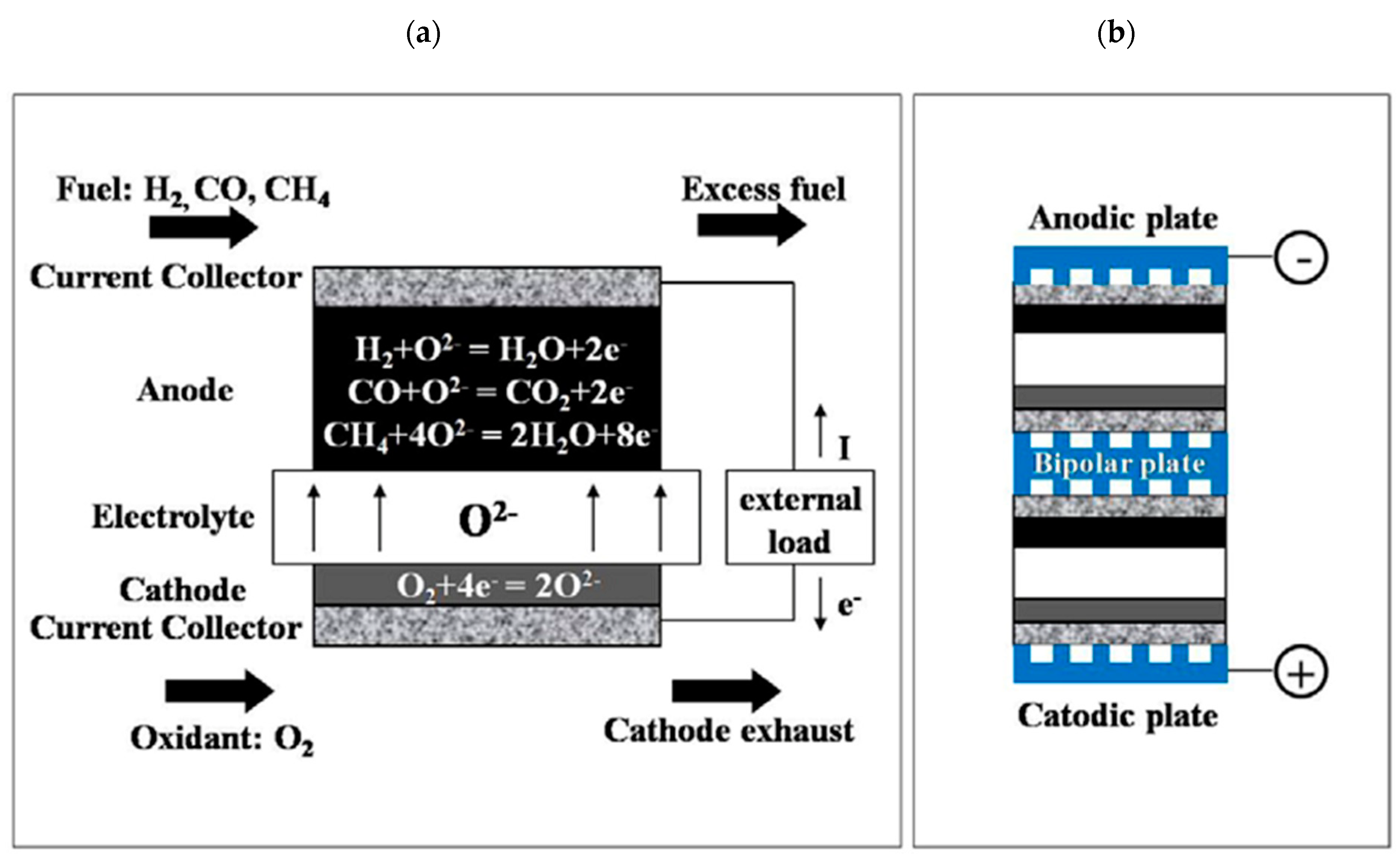
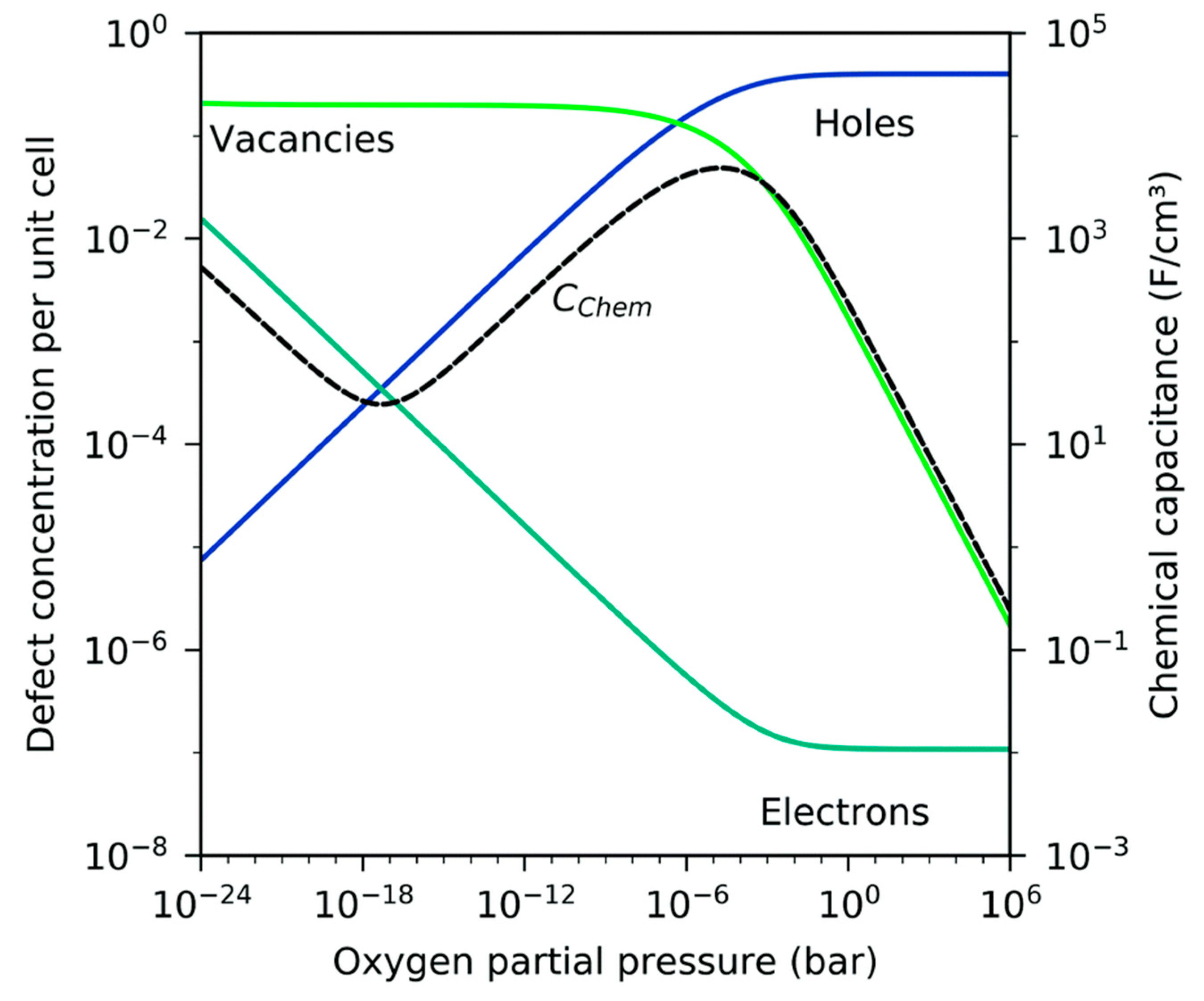
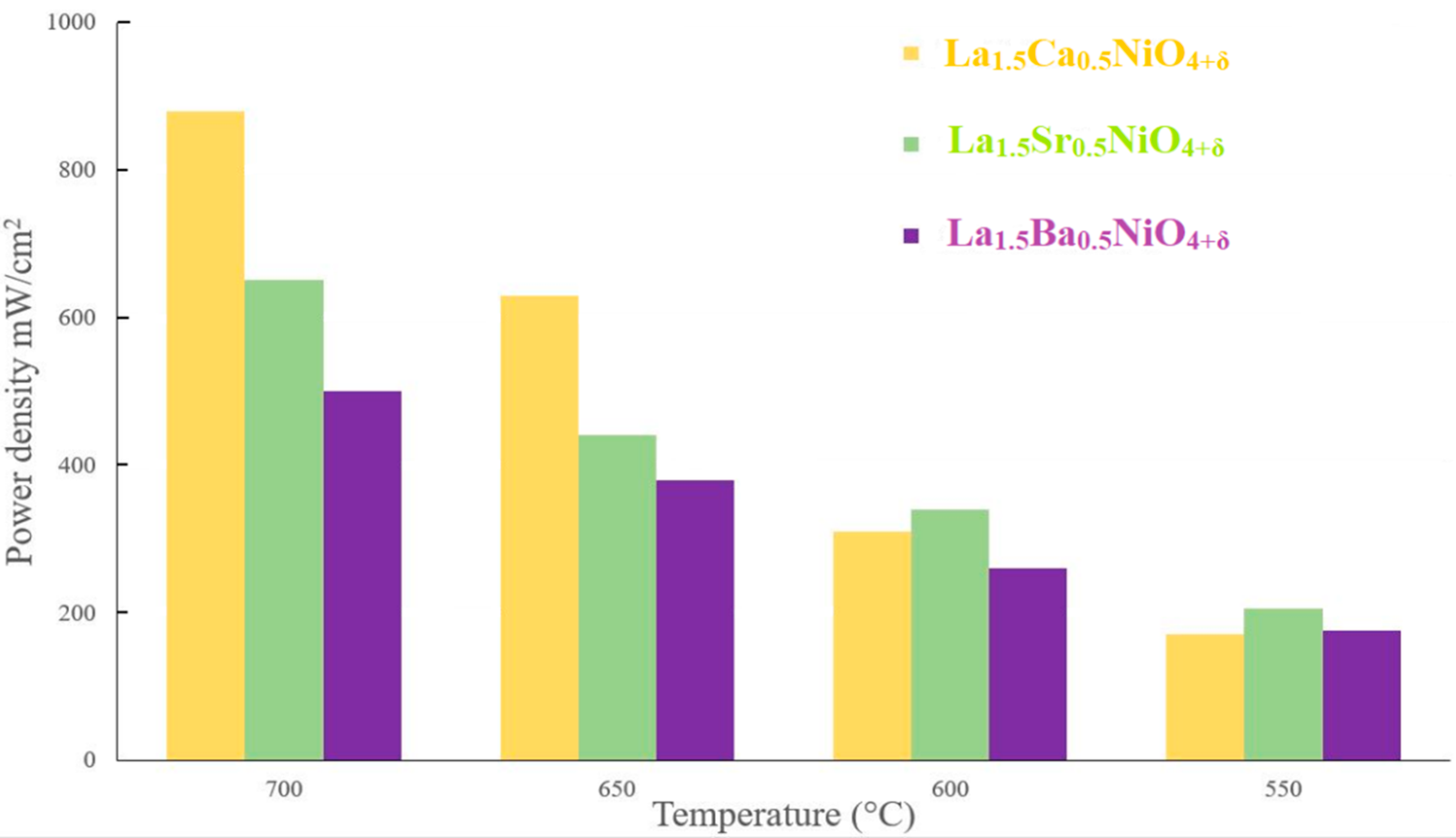
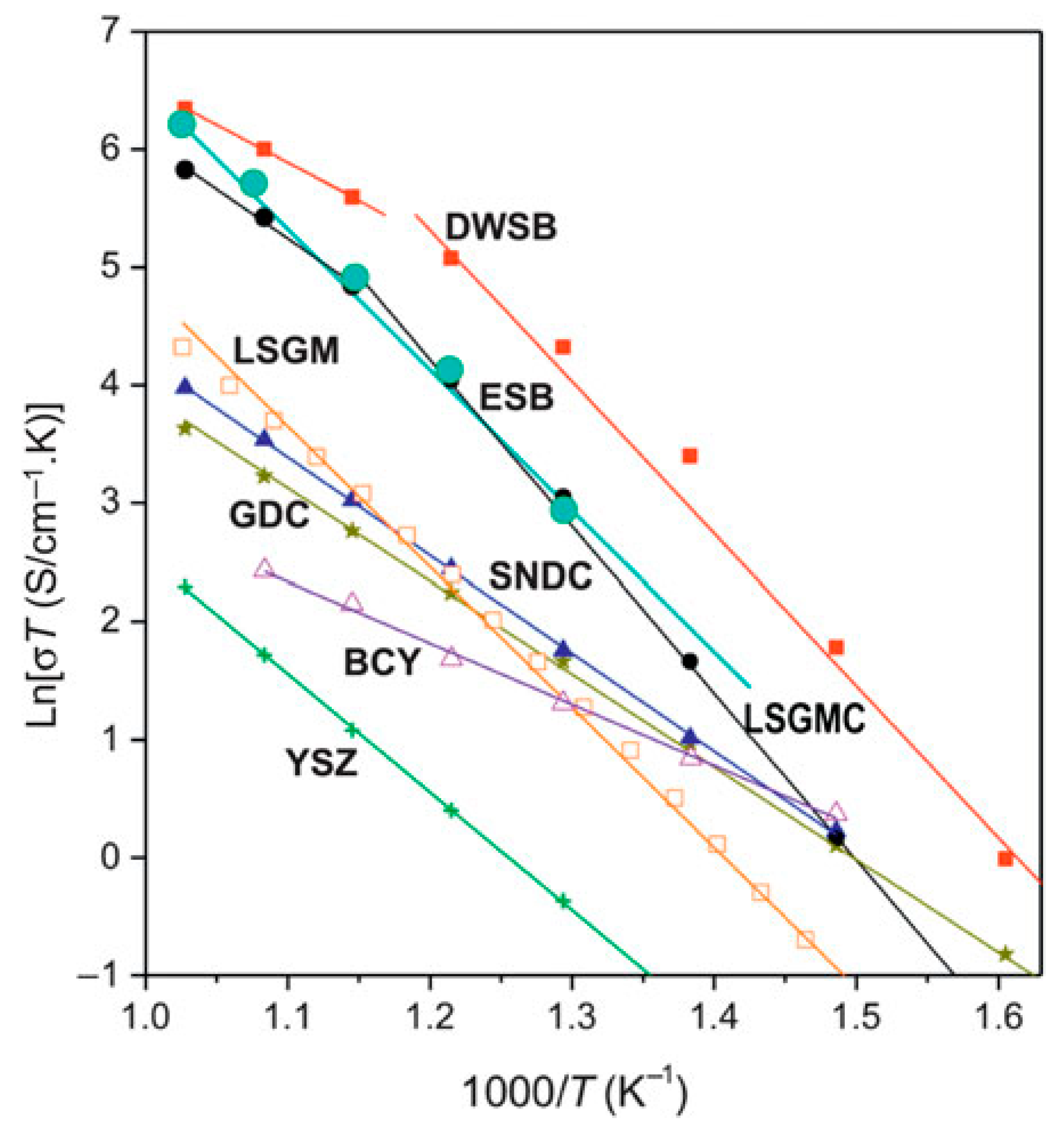
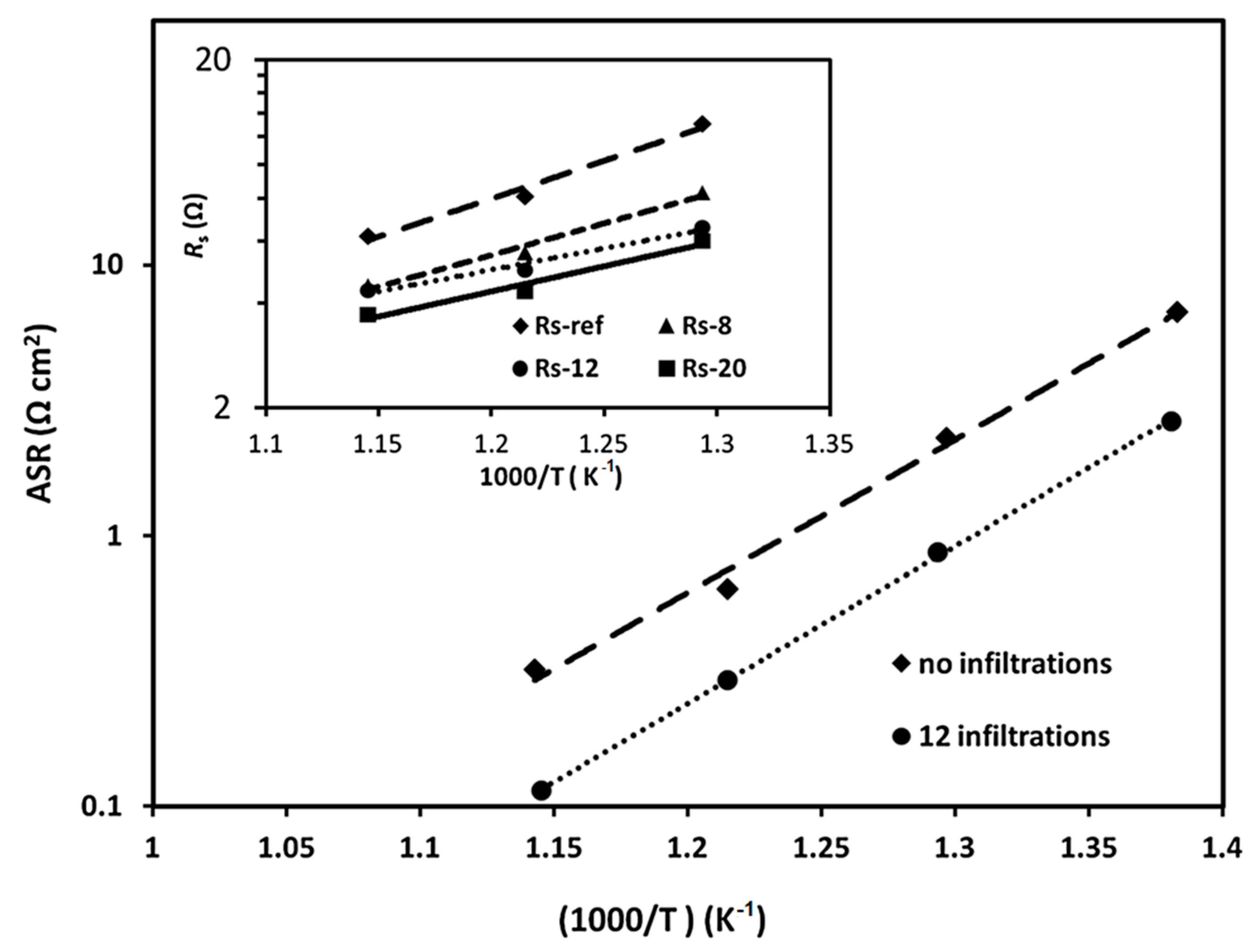
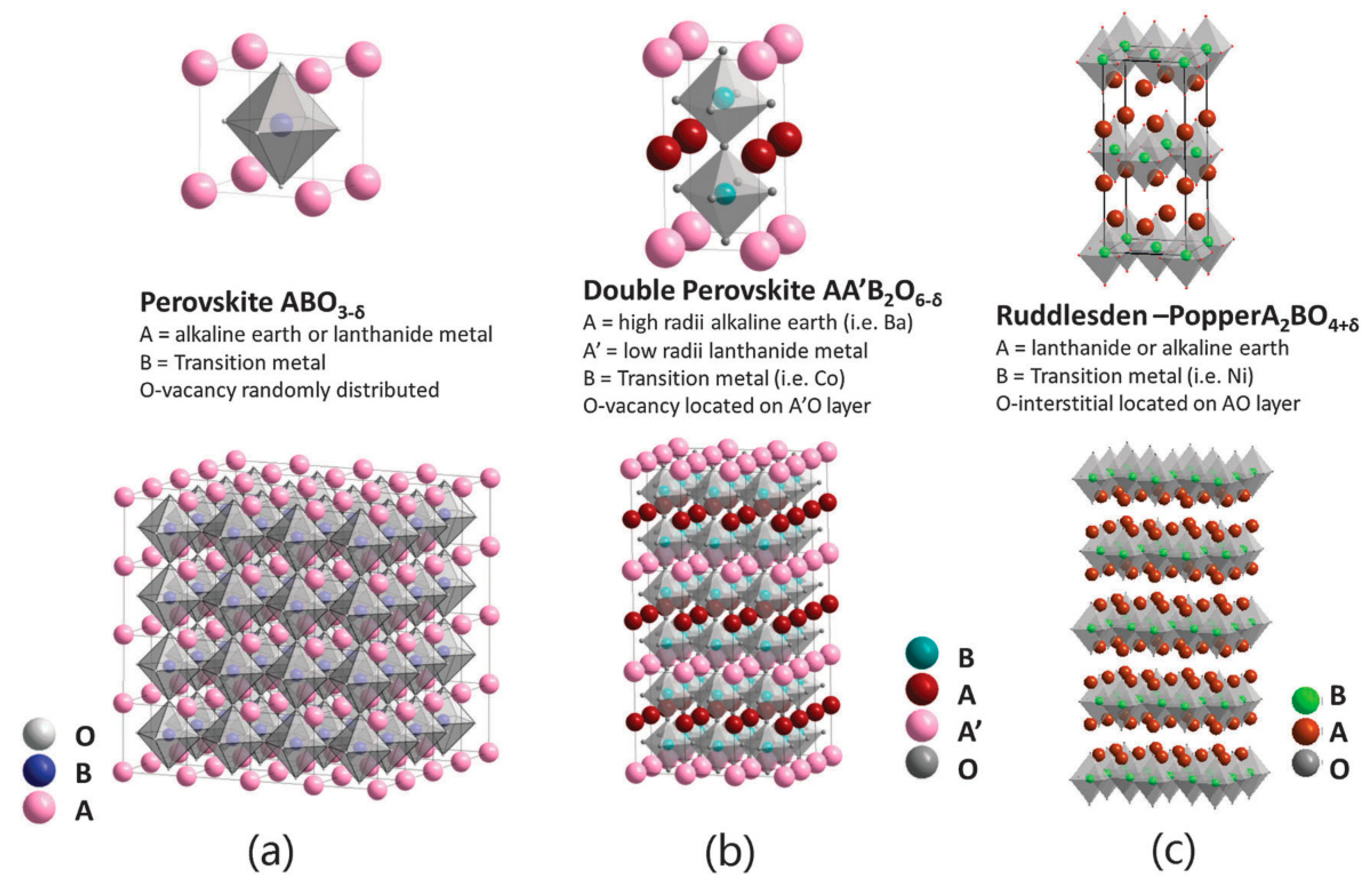
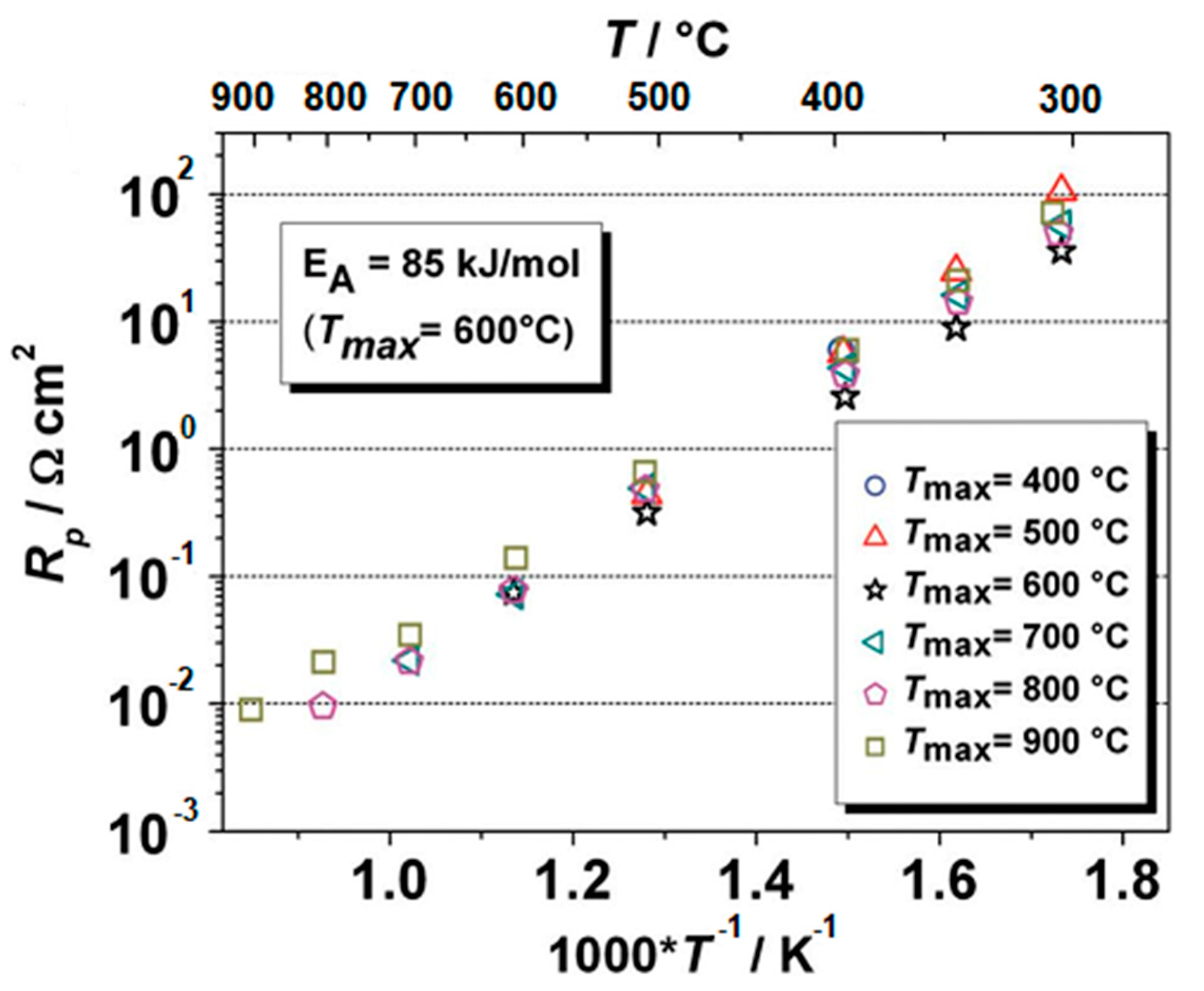
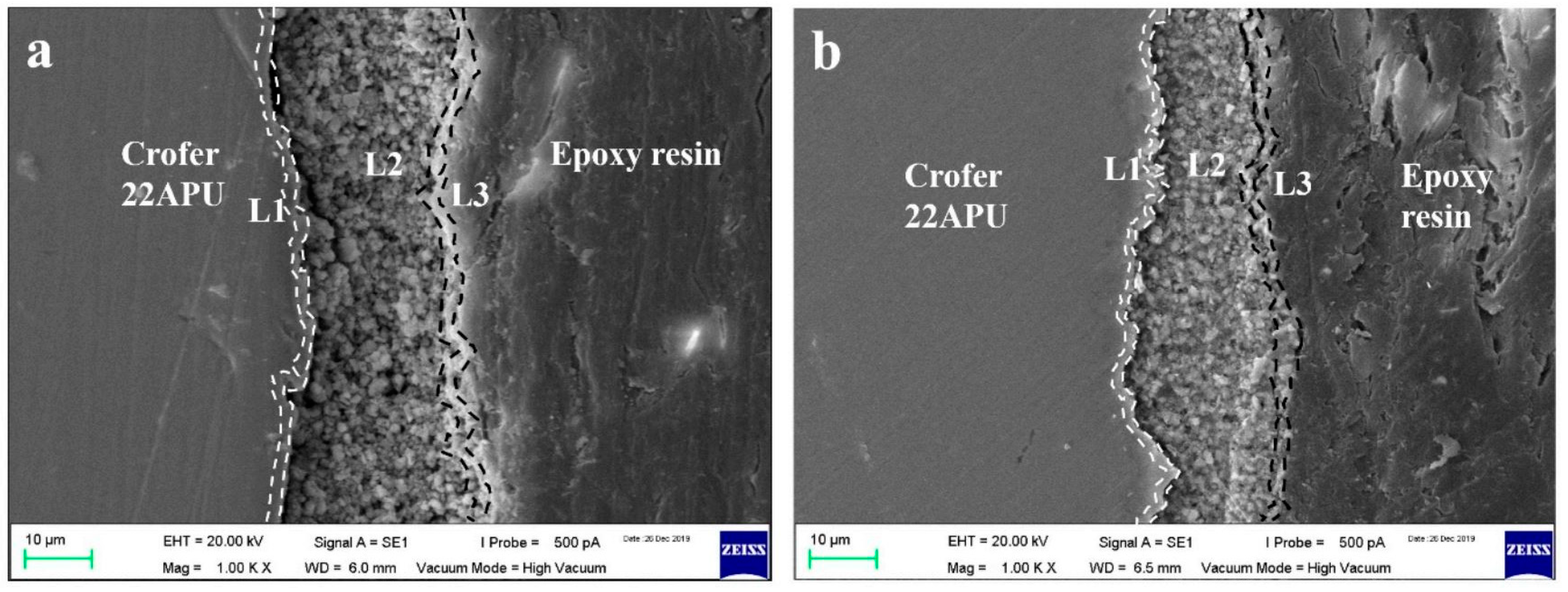
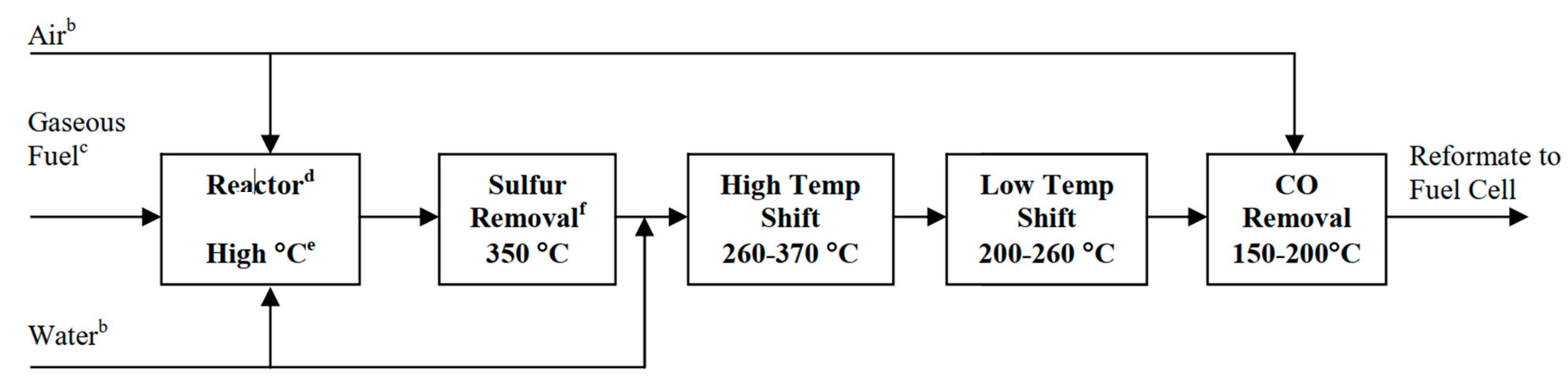
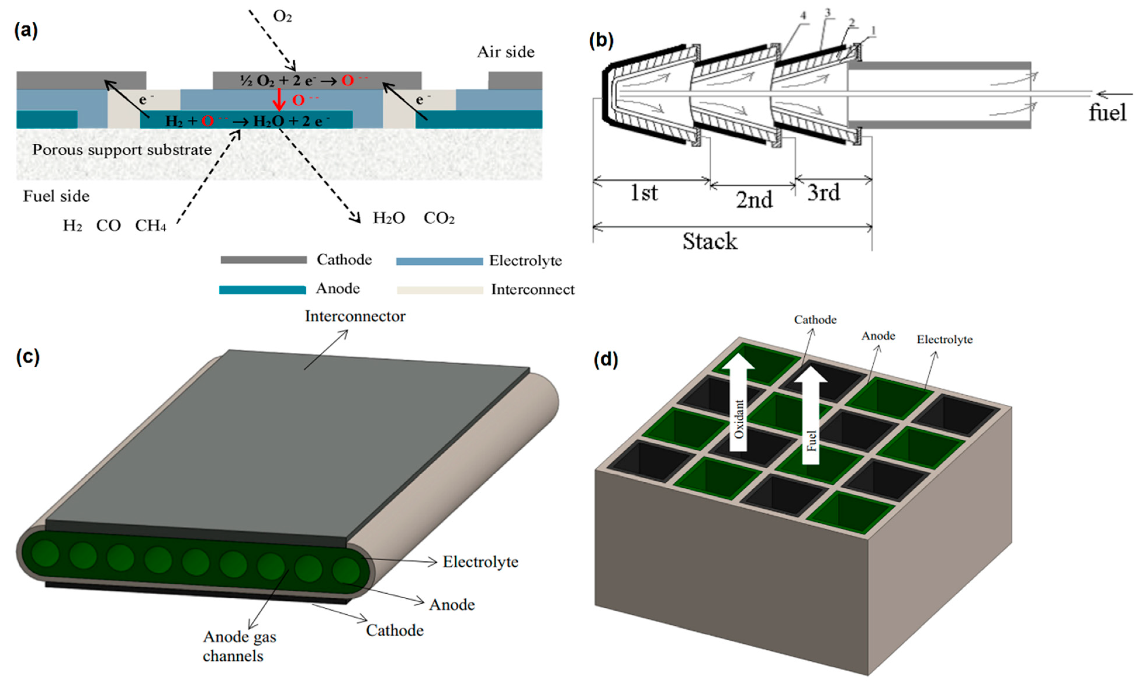
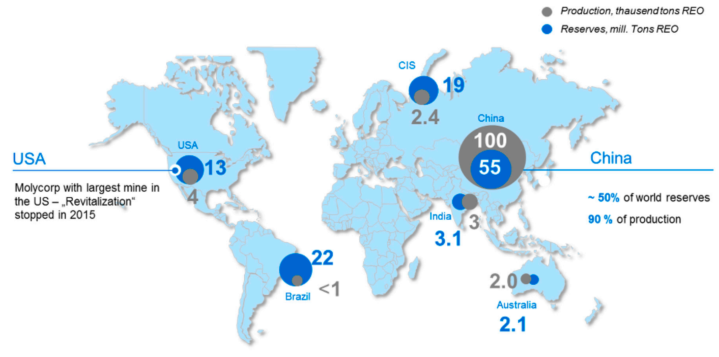
 [Green Version]
Figure 1. Schematic of (a) Solid oxide fuel cells (SOFC) operation and (b) Single cells assembly in-series [36].
Energies 14 01280 g001
Figure 2. Brouwer diagram of lanthanum strontium ferrite (LSF) at 600 °C [54].
Energies 14 01280 g002
Figure 3. Maximum power density of La1.5A0.5NiO4+δ (A = Ca, Sr, or Ba) layered perovskite mixed ionic-electronic conductors (MIEC) at different temperatures [61].
Energies 14 01280 g003
Figure 4. Log(σ) vs. Log (pO2) for 8YSZ-4Yb2O3 and 8YSZ-4Yb2O3-NaCl/KCl [143].
Energies 14 01280 g004
Figure 5. Ionic conductivity of various oxide electrolytes against temperature (ESB: Er0.4Bi1.6O3; DWSB: Dy0.08W0.04Bi0.88O1.56; GDC: Gd0.1Ce0.1O1.95; SNDC: Sm0.075Nd0.075Ce0.85Ce0.85O2; YSZ: Y0.16Zr0.84O1.92; LSGM: La0.8Sr0.2Ga0.8Mg0.2O3; LSGMC: La0.8Sr0.2Ga0.8Mg0.115Co0.085O3; BCY: BaCe0.92Y0.08O3) [190].
Energies 14 01280 g005
Figure 6. Electrochemical performance of low-temperature SOFC with ZnO and ZnO-LCP electrolytes at different temperatures [141].
Energies 14 01280 g006
Figure 7. The Area Specific Resistance (ASR) as a function of temperature for the NiO-GDC anodes without and with 12 infiltration cycle [248].
Energies 14 01280 g007
Figure 8. Crystal structure of (a) perovskite, (b) double perovskite, and (c) Ruddlesden–Popper phases (Reproduced with permission from [107], Royal Society of Chemistry (RSC), 2016).
Energies 14 01280 g008
Figure 9. Polarization resistance as a function of operating temperature at different firing temperatures (Reproduced with permission from [271], Institute of Physics (IOP), 2011).
Energies 14 01280 g009
Figure 10. SEM images of Crofer 22 APU (a) before and (b) after annealing coated with 3 different layers, namely (L1: chromia), (L2: spinel), and (L3: CuO) [291].
Energies 14 01280 g010
Figure 11. Schematic of the steps in a typical fuel processor for low-temperature SOFCs [41].
Energies 14 01280 g011
Figure 12. (a) Integrated planar (IP)-SOFC cell design [309], (b) cone-shaped SOFC design (1. anode; 2. electrolyte; 3. cathode; and 4. current collector) (Reproduce with permission from [320], Institute of Physics (IOP), 2007), (c) flat-tube SOFC design, and (d) honeycomb SOFC design (Reproduced with permission from [311], Elsevier, 2016).
Energies 14 01280 g012
Figure 13. The effect of the length to area L/A ratio on the ASR of different cell geometry (Reproduced with permission from [284], Wiley, 2010).
Energies 14 01280 g013
Figure 14. Rare earth elements mining sites throughout the world [353].
Energies 14 01280 g014
Table 1. Advantages and disadvantages of the common SOFCs geometries.
Cell GeometryStrengthWeakness
Anode-supported
-
Highly conductive anode
-
Low operating temperature
-
Re-oxidation
-
Gas transportation
Electrolyte-supported
-
Strong backbone
-
Uniform current density
-
Higher resistance
-
Requires higher operating temperature for diminishing ohmic losses
Cathode-supported
-
Low operating temperature
-
No oxidation
-
Low conductivity
-
Gas transportation issues
Metal-supported
-
Excellent structural robustness
-
High tolerance toward rapid thermal cycling
-
Excellent electrical and thermal conductivity
-
Oxidation at high temperatures
-
Moderate the cell electrochemical performance
-
Thermal expansion mismatch between individual cell parts
-
High cost of fabrication
Table 2. The fabrication method, operating temperature, and ionic conductivity of low-temperature electrolytes.
MaterialFabrication MethodConductivity (S·cm−1)Temperature (°C)Ref.
GDC-1 × 10−1800[146]
Ce0.80Sm0.10In0.10O1.90Pechini method6.009 × 10−3650[147]
Ce0.80Gd0.17Pr0.03O1.90Spray-freezing/freeze-drying3.1 × 10−2750[166]
La9.5Ba0.5Si5.5Al0.5O26.5Solid-state reaction2.21 × 10−2800[167]
La9.4Ba0.6Si6O26.7Solid-state reaction~1.1 × 10−1750[168]
La9.83Si5Al0.75Fe0.25O26±δMechanochemical activation2.04 × 10−2700[169]
La10Si4.5Cu1.5O27-δSol–gel4.8 × 10−2800[170]
La10Si5.8Mg0.2O26.8Solid-state reaction8.8 × 10−2800[171]
La9.8Si5.7Mg0.3O26.4Solid-state reaction7.4 × 10−2800[171]
La9.53Si5.7Mg0.3O26Solid-state reaction4.4 × 10−2800[172]
La0.8Sr0.2Ga0.85Mg0.15O2.825Sol–gel1.1 × 10−1800[165]
La0.85Sr0.15Ga0.85Mg0.15O3−δSolid-state reaction1.77 × 10−1800[173]
La0.8Sr0.2Ga0.83Mg0.17O2.815Solid-state reaction1.7 × 10−1800[174]
BaZr0.8Y0.20O3−δSolid-state reaction~1.5 × 10−5900[175]
BaCe0.9Y0.10O3−δSolid-state reaction~2.5 × 10−2800[176]
BaCe0.85Sm0.15O3−δSolid-state reaction4.75 × 10−2800[177]
Ba1−xSrxCe0.5Zr0.35Y0.1Sm0.05O3−δSolid-state reaction2.391 × 10−3700[178]
Table 3. The fabrication method, operating temperature, and ionic conductivity of low-temperature electrolytes.
MaterialFabrication MethodConductivity (S·cm−1)Temperature (°C)Ref.
SCDCCo-precipitation3.9 × 10−2600[185]
LSCF-SCDCCo-precipitation1.88 × 10−1600[185]
SDC-(Li/Na/K)2CO3Co-precipitation~0.7 × 10−1550[112]
SDC-(35 wt. % lithium-sodium carbonate)Solid-state reaction1.4 × 10−1550[203]
SDC-(lithium-potassium carbonate)Solid-state reaction7 × 10−2550[213]
SDC-Na2CO3Solid-state reaction~7 × 10−2550[204]
GDC-25 wt. % (Li-Na)2CO3Co-precipitation1.757 × 10−1550[180]
GDC-40 wt. % (Li-Na)2CO3Simple one-step dry-processing1.8 × 10−1500[209]
LSGM-(Li/Na)2CO3Polyacrylamide gel combustion process~1.2 × 10−1600[211]
Ce0.8Sm0.2O1.9-Na2CO3Tape casting and hot press1 × 10−1550[228]
Ce0.80Sm0.1Gd0.1O1.9Citrate complexation process1.8 × 10−2600[229]
Ce0.80La0.18Ca0.02O1.9Citrate/nitrate gel auto-combustion1.28 × 10−2600[132]
Ce0.80Nd0.18Y0.02O1.90Citrate/nitrate gel auto-combustion 1.28 × 10−2600[132]
Ce0.83Dy0.13Ca0.03O2−δCitrate/nitrate gel auto-combustion 1.45 × 10−2600[186]
Ce0.85La0.10Ca0.05O2−δSolid-state reaction~1.8 × 10−2600[150]
GDC-KAlZnSolid-state thermal pyrolysis6 × 10−2580[201]
Bi/Gd co-doped ceriaSol–gel combustion synthesis1.29 × 10−2600[189]
Ce0.80Sm0.1Y0.1O1.9Sol–gel1.44 × 10−2600[148]
10Sc1CeSZTape casting2.1 × 10−2600[193]
1Ce9ScSZCombustion~1.1 × 10−2600[194]
BZCY7Solid-state reaction9 × 10−3500[230]
ZnOSolid-state reaction9 × 10−2550[141]
ZnO-LCPSolid-state reaction1.56 × 10−1550[141]
3ZnO-7LCPSolid-state blending2.9 × 10−1550[13]
La10Si6O27Solid-state reaction5.8 × 10−3500[172]
La9.533(Si5.7Mg0.3)O26Solid-state reaction7.4 × 10−3500[172]
(La9.33Sr0.67)Si6O26.67Solid-state reaction6.6 × 10−3500[172]
La9BaSi6O26.5Solid-state reaction6.6 × 10−3500[219]
La10Si5GaO26.5Solid-state reaction2.4 × 10−3500[219]
La9.67Si5.5Mg0.5O26Solid-state reaction3 × 10−3500[231]
(Dy2O3)13(Ta2O5)2(Bi2O3)85Solid-state reaction8 × 10−2500[227]
10T5WSBSolid-state reaction6.34 × 10−2500[223]
8D4WSBSolid-state reaction9.8 × 10−2500[159]
13D2TSBSolid-state reaction8 × 10−2500[227]
Publisher’s Note: MDPI stays neutral with regard to jurisdictional claims in published maps and institutional affiliations.

