
Configurations, Power Topologies and Applications of Hybrid Distribution Transformers

 , ,
, ,  , , and
Abstract
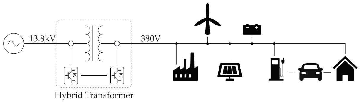
1. Introduction
2. Hybrid Transformer Configurations
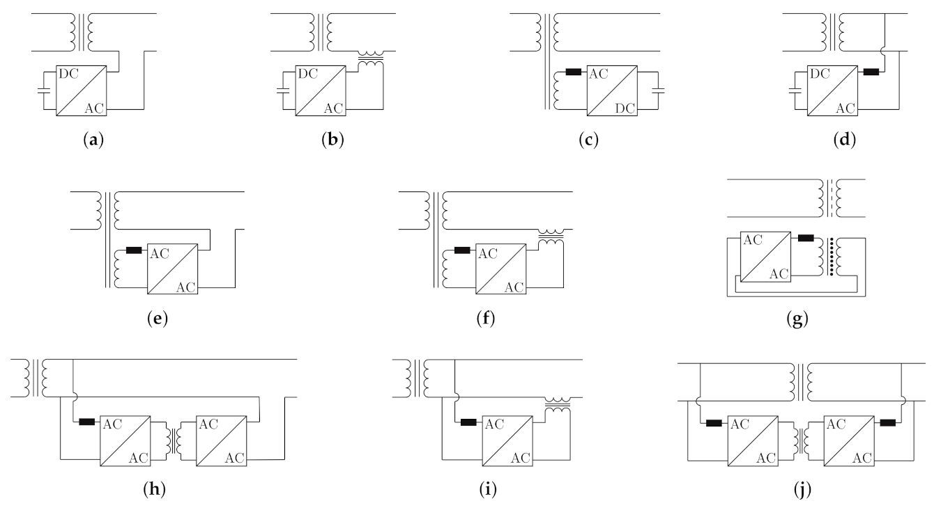
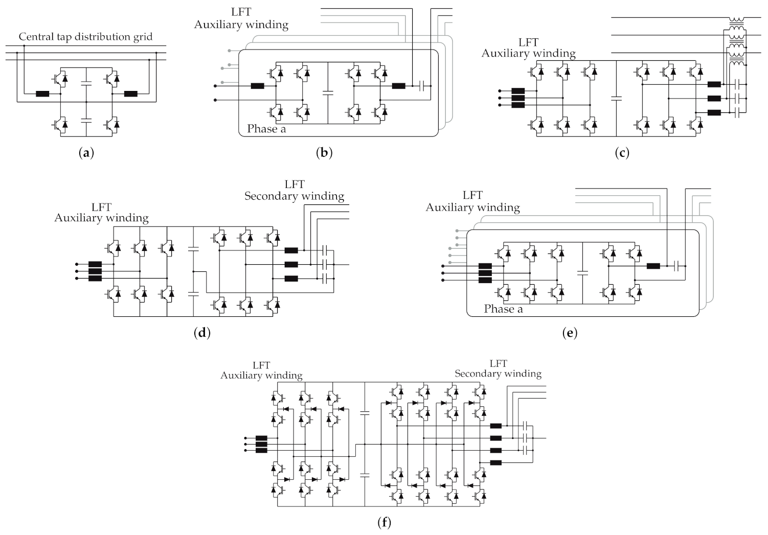
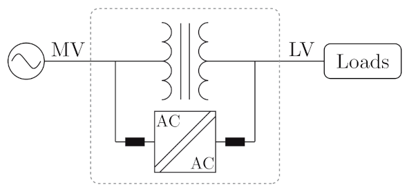
2.1. Self-Supported Hybrid Transformers
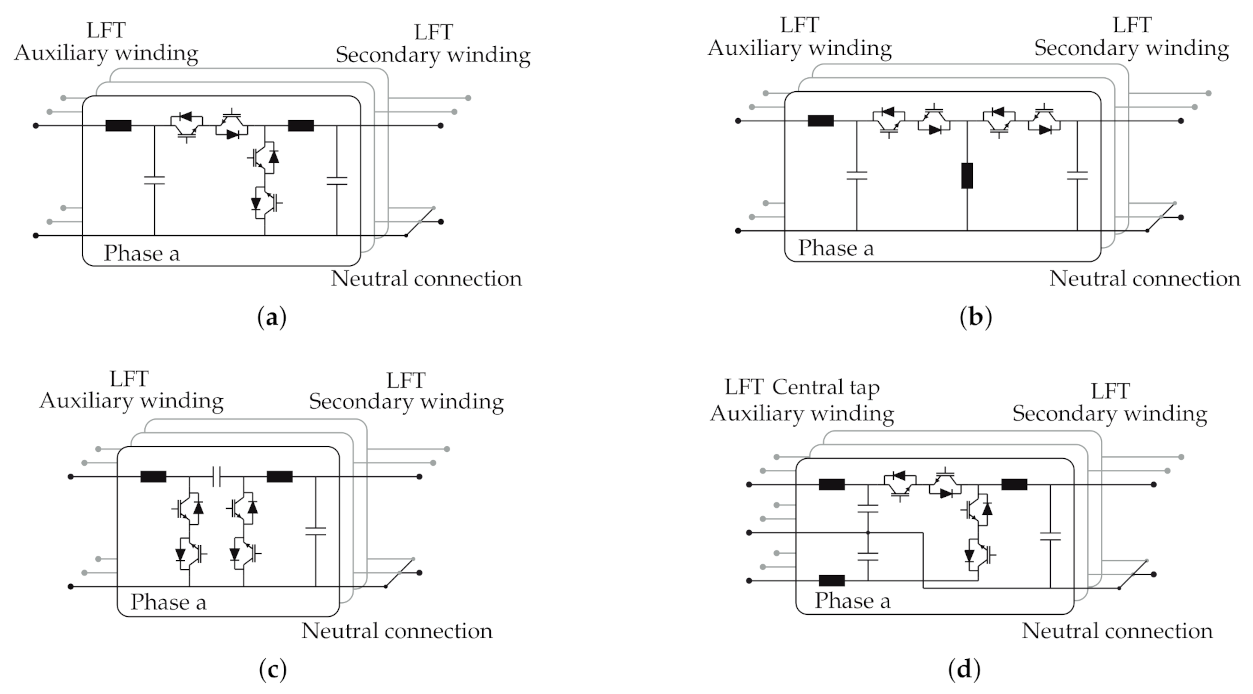
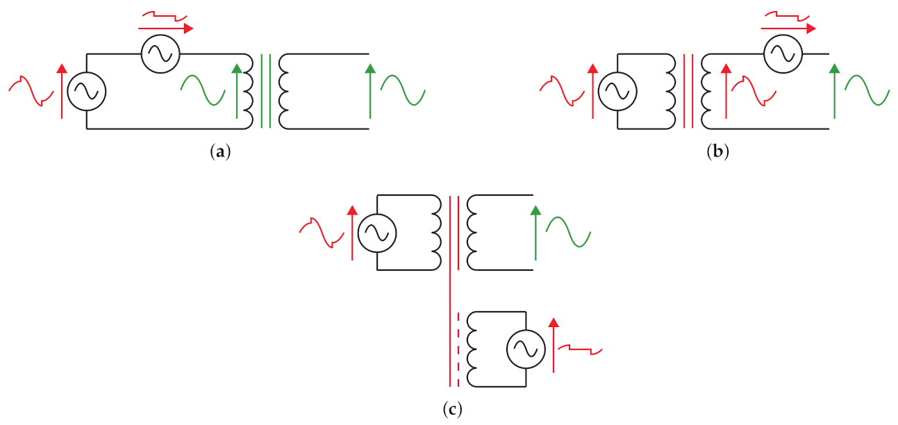
2.2. Hybrid Transformers Connected to Auxiliary Windings
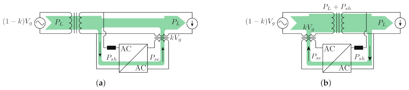
2.3. Hybrid Transformers Connected to Transformer Windings
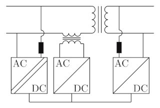
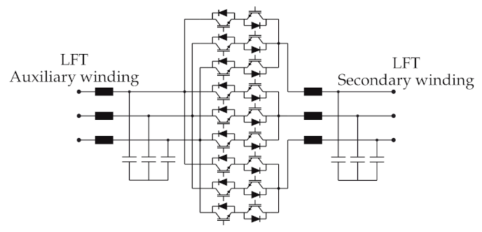
2.4. Three-Stage Configuration
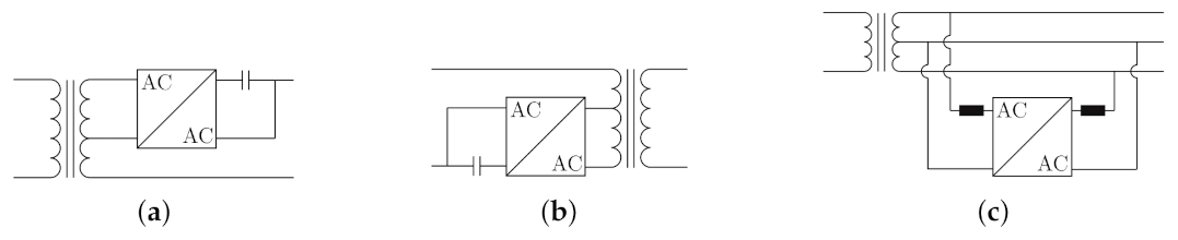
2.5. Additional HDT Configurations
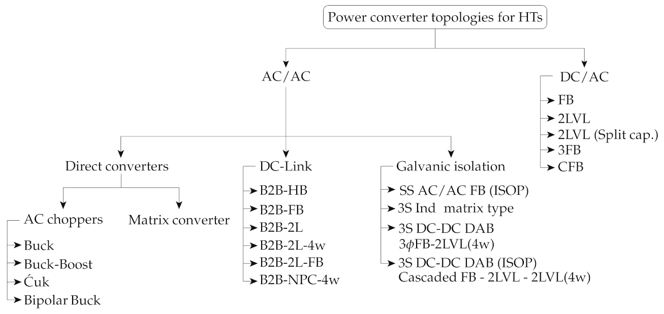
3. Power Converter Topologies Employed for Hybrid Transformers
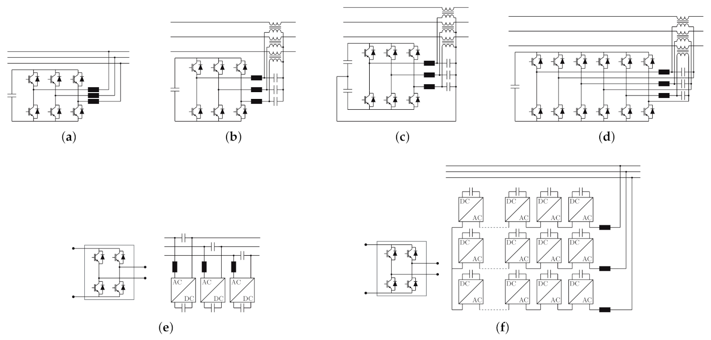
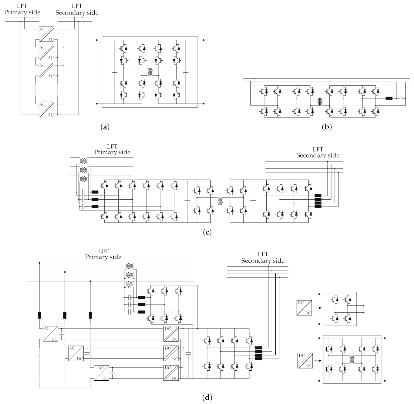
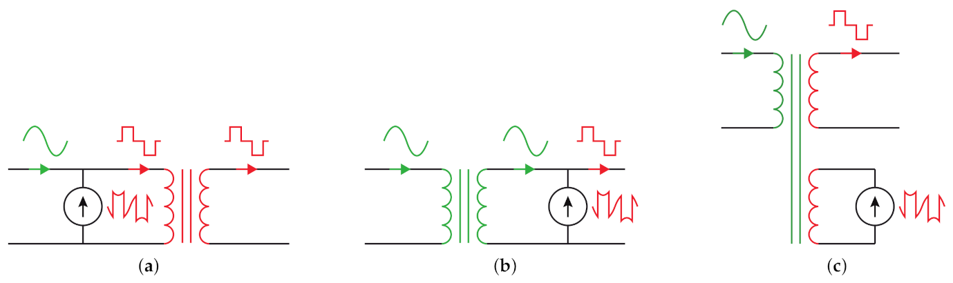
3.1. DC/AC Power Converter Topologies
3.2. AC/AC Power Converter Topologies
3.2.1. AC/AC Converters Based on Direct Converters
3.2.2. AC/AC Converters with a DC-Link Stage
3.2.3. AC/AC Converters with Galvanic Isolation
4. Analysis of Hybrid Transformers
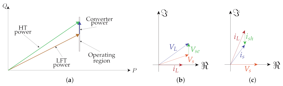
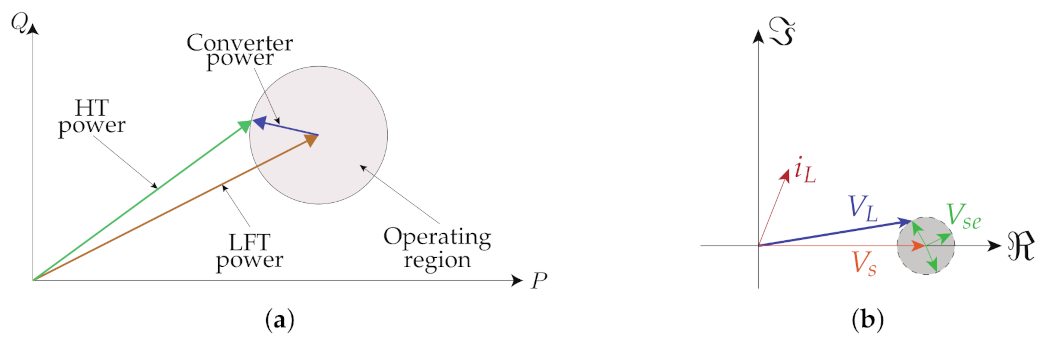
4.1. Operating Region
4.1.1. Reactive Power Injection
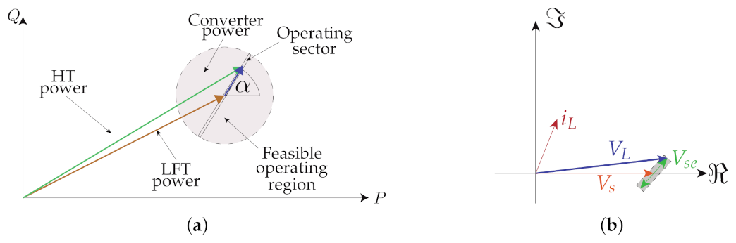
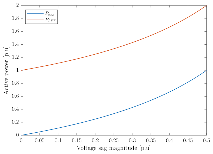
4.1.2. Restricted Active and Reactive Power Injection
4.1.3. Unrestricted Active and Reactive Power Injection
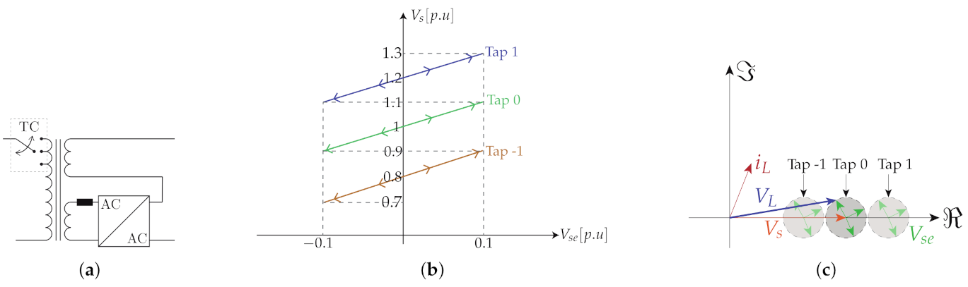
4.1.4. Use of Tap Changers Systems to Extend the HDT Operating Region
4.2. Power Converter Location Effects
4.2.1. Shunt Converter Location
4.2.2. Series Converter Location
4.2.3. Combined Compensation and Circulating Active Power Flow
4.3. Losses in Distribution Transformers
4.4. LFT Protection
4.4.1. Self-Supported HDT
4.4.2. HDT Connected to Auxiliary Windings
4.4.3. HDT Connected to the LFT Primary or Secondary Windings
4.5. HDT Reliability
5. Ancillary Services Provided by Hybrid Transformers
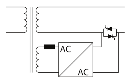
5.1. Distribution Transformer Inrush Current Mitigation
5.2. Distribution Transformer Additional Capacity
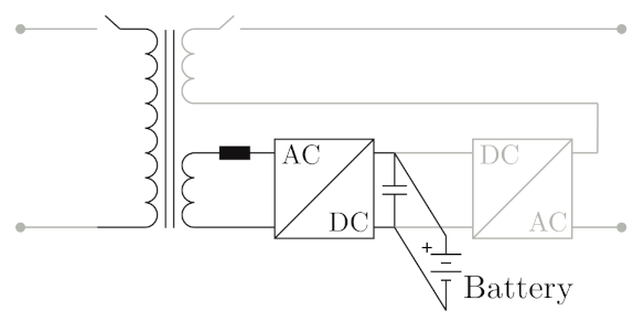
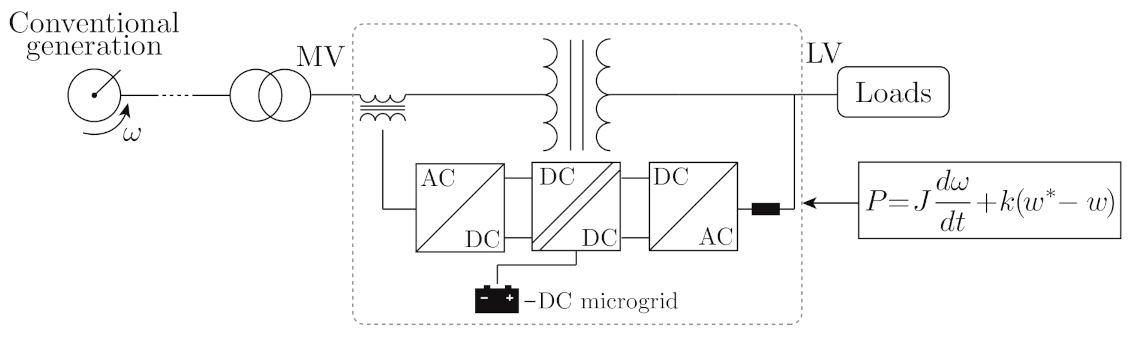
5.3. Hybrid Transformers to Provide Virtual Inertia
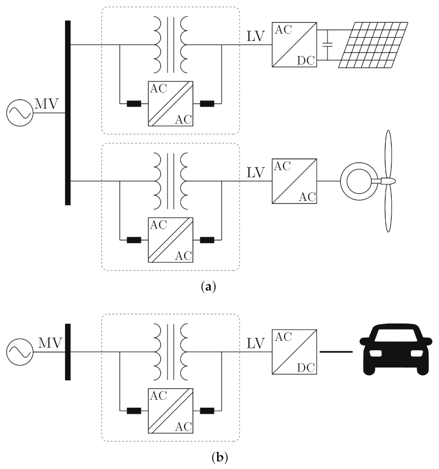
5.4. Renewable Energy Systems and New Kind of Loads Integration
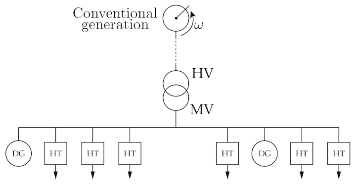
5.5. Decentralized Control of a HDT for Voltage Regulation in Active Networks
6. Conclusions
Author Contributions
Funding
Institutional Review Board Statement
Informed Consent Statement
Data Availability Statement
Conflicts of Interest
References
- Gönen, T. Electric Power Distribution System Engineering, 3rd ed.; CRC Press: Boca Raton, FL, USA, 2014. [Google Scholar]
- Ciuriuc, A.; Dumitran, L.M.; Notingher, P.V.; Badicu, L.V.; Setnescu, R.; Setnescu, T. Lifetime Estimation of Vegetable and Mineral Oil Impregnated Paper for Power Transformers. In Proceedings of the 2016 IEEE International Conference on Dielectrics (ICD), Montpellier, France, 3–7 July 2016; Volume 2, pp. 720–723. [Google Scholar]
- Fuchs, E.; Masoum, M. Power Quality in Power Systems and Electrical Machines, 2nd ed.; Academic Press: Cambridge, MA, USA, 2015. [Google Scholar]
- IEEE. IEEE Recommended Practice for Monitoring Electric Power Quality, IEEE Std 1159-2019; IEEE: New York, NY, USA, 2019; pp. 1–98. [Google Scholar]
- IEEE. IEEE Recommended Practice and Requirements for Harmonic Control in Electric Power Systems, IEEE Std 519-2014; IEEE: New York, NY, USA, 2014; pp. 1–29. [Google Scholar]
- Singh, B.; Chandra, A.; Al-Haddad, K. Power Quality: Problems and Mitigation Techniques; Wiley: Hoboken, NJ, USA, 2015. [Google Scholar]
- Sharma, A.; Rajpurohit, B.S.; Singh, S.N. A Review on Economics of Power Quality: Impact, Assessment and Mitigation. Renew. Sustain. Energy Rev. 2018, 88, 363–372. [Google Scholar] [CrossRef]
- IEEE. IEEE Recommended Practice for Establishing Liquid Immersed and Dry-Type Power and Distribution Transformer Capability When Supplying Nonsinusoidal Load Currents, IEEE Std C57.110-2018; IEEE: New York, NY, USA, 2018; pp. 1–68. [Google Scholar]
- Kefalas, T.D.; Kladas, A.G. Harmonic Impact on Distribution Transformer No-Load Loss. IEEE Trans. Ind. Electron. 2010, 57, 193–200. [Google Scholar] [CrossRef]
- Dao, T.; Phung, B.T. Effects of Voltage Harmonic on Losses and Temperature Rise in Distribution Transformers. IET Gener. Transm. Distrib. 2018, 12, 347–354. [Google Scholar] [CrossRef]
- Mazzanti, G.; Lusetti, L.; Fragiacomo, A. The State of the Art About Electric Arc Furnaces for Steel Use and the Compensation of Their Perturbing Effects on the Grid. In Proceedings of the International Symposium on Power Electronics Power Electronics, Electrical Drives, Automation and Motion, Sorrento, Italy, 20–22 June 2012; pp. 1277–1282. [Google Scholar]
- Awadallah, M.A.; Venkatesh, B.; Singh, B.N. Impact of Solar Panels on Power Quality of Distribution Networks and Transformers. Can. J. Electr. Comput. Eng. 2015, 38, 45–51. [Google Scholar] [CrossRef]
- Ustun, T.S.; Hashimoto, J.; Otani, K. Impact of Smart Inverters on Feeder Hosting Capacity of Distribution Networks. IEEE Access 2019, 7, 163526–163536. [Google Scholar] [CrossRef]
- Kraiczy, M.; Stetz, T.; Braun, M. Parallel Operation of Transformers With on Load Tap Changer and Photovoltaic Systems With Reactive Power Control. IEEE Trans. Smart Grid 2018, 9, 6419–6428. [Google Scholar] [CrossRef]
- Paterakis, N.G.; Pappi, I.N.; Erdinc, O.; Godina, R.; Rodrigues, E.M.G.; Catalao, J.P.S. Consideration of the Impacts of a Smart Neighborhood Load on Transformer Aging. IEEE Trans. Smart Grid 2016, 7, 2793–2802. [Google Scholar] [CrossRef]
- Hilshey, A.D.; Hines, P.D.; Rezaei, P.; Dowds, J.R. Estimating the Impact of Electric Vehicle Smart Charging on Distribution Transformer Aging. IEEE Trans. Smart Grid 2013, 4, 905–913. [Google Scholar] [CrossRef]
- Santos-Martin, D.; Lemon, S.; Watson, J.D.; Wood, A.R.; Miller, A.J.; Watson, N.R. Impact of Solar Photovoltaics on the Low-Voltage Distribution Network in New Zealand. IET Gener. Transm. Distrib. 2016, 10, 1–9. [Google Scholar]
- Gong, Q.; Midlam-Mohler, S.; Marano, V.; Rizzoni, G. Study of PEV Charging on Residential Distribution Transformer Life. IEEE Trans. Smart Grid 2012, 3, 404–412. [Google Scholar] [CrossRef]
- Faiz, J.; Siahkolah, B. Electronic Tap-Changer for Distribution Transformers; Springer: Berlin/Heidelberg, Germany, 2011. [Google Scholar]
- Das, B.P.; Radakovic, Z. Is Transformer kVA Derating Always Required Under Harmonics? A Manufacturer’s Perspective. IEEE Trans. Power Deliv. 2018, 33, 2693–2699. [Google Scholar] [CrossRef]
- Abu-Siada, A.; Budiri, J.; Abdou, A. Solid State Transformers Topologies, Controllers, and Applications: State-of-the-Art Literature Review. Electronics 2018, 7, 298. [Google Scholar] [CrossRef]
- Huber, J.E.; Kolar, J.W. Solid-State Transformers: On the Origins and Evolution of Key Concepts. IEEE Ind. Electron. Mag. 2016, 10, 19–28. [Google Scholar] [CrossRef]
- Huang, A.; Zhu, Q.; Wang, L.; Zhang, L. 15 kV SiC MOSFET: An Enabling Technology for Medium Voltage Solid State Transformers. CPSS Trans. Power Electron. Appl. 2017, 2, 118–130. [Google Scholar] [CrossRef]
- Bala, S.; Das, D.; Aeloiza, E.; Maitra, A.; Rajagopalan, S. Hybrid Distribution Transformer: Concept Development and Field Demonstration. In Proceedings of the 2012 IEEE Energy Conversion Congress and Exposition (ECCE), Raleigh, NC, USA, 15–20 September 2012; pp. 4061–4068. [Google Scholar]
- Burkard, J.; Biela, J. Hybrid Transformers for Power Quality Enhancements in Distribution Grids—Comparison to Alternative Concepts. In Proceedings of the NEIS 2018; Conference on Sustainable Energy Supply and Energy Storage Systems, Hamburg, Germany, 20–21 September 2018; pp. 1–6. [Google Scholar]
- Burkard, J.; Biela, J. Design of a Protection Concept for a 100kVA Hybrid Transformer. IEEE Trans. Power Electron. 2019, 35, 3543–3557. [Google Scholar] [CrossRef]
- Burkard, J.; Biela, J. Protection of Hybrid Transformers in the Distribution Grid. In Proceedings of the 2016 18th European Conference on Power Electronics and Applications (EPE’16 ECCE Europe), Karlsruhe, Germany, 5–9 September 2016; pp. 1–10. [Google Scholar]
- Sastry, J.; Bala, S. Considerations for the Design of Power Electronic Modules for Hybrid Distribution Transformers. In Proceedings of the 2013 IEEE Energy Conversion Congress and Exposition, ECCE 2013, Denver, CO, USA, 15–19 September 2013; pp. 1422–1428. [Google Scholar]
- Huber, J.E.; Kolar, J.W. Applicability of Solid-State Transformers in Today’s and Future Distribution Grids. IEEE Trans. Smart Grid 2019, 10, 317–326. [Google Scholar] [CrossRef]
- Bala, S. Distribution Transformer. EU Patent PCT/US2013/056393, 23 August 2013. [Google Scholar]
- Haj-Maharsi, M.Y.; Sandeep, B.; Tang, L. Hybrid Distribution Transformer with an Integrated Voltage Source Converter. US Patent US 201O/O220499 A1, 2 February 2010. [Google Scholar]
- Haj-Maharsi, M.Y.; Tang, L.; Gutierrez, R.; Bala, S. Hybrid Distribution Transformer with AC & DC Power Capabilities. US Patent US 2010/0201338 A1, 12 August 2010. [Google Scholar]
- Haj-Maharsi, M.Y.; Tang, L.; Gutierrez, R.; Bala, S. Hybrid Distribution Transformer Having a Power Electronic Module for Controlling Input Power Factor and Output Voltage. US Patent US 9768704 B2, 19 September 2017. [Google Scholar]
- Takahashi, Y.; Isobe, T.; Tadano, H. Series Reactive Power Compensator with Reduced Capacitance for Hybrid Transformer. In Proceedings of the 2018 International Power Electronics Conference (IPEC-Niigata 2018 -ECCE Asia), Niigata, Japan, 20–24 May 2018; pp. 3375–3382. [Google Scholar]
- Omar, R.; Rahim, N.A. Voltage Unbalanced Compensation Using Dynamic Voltage Restorer Based on Supercapacitor. Int. J. Electr. Power Energy Syst. 2012, 43, 573–581. [Google Scholar] [CrossRef]
- Newman, M.J.; Holmes, D.G.; Nielsen, J.G.; Blaabjerg, F. A Dynamic Voltage Restorer (DVR) With Selective Harmonic Compensation at Medium Voltage Level. IEEE Trans. Ind. Appl. 2005, 41, 1744–1753. [Google Scholar] [CrossRef]
- Liu, Q.; Li, Y.; Liu, F.; Hu, S.; Xie, B.; Luo, L.; Cao, Y. A Controllably Inductive Power Filtering Method for Large-Power Industrial Rectifier System. In Proceedings of the 2016 IEEE 16th International Conference on Environment and Electrical Engineering (EEEIC), Florence, Italy, 7–10 June 2016. [Google Scholar]
- Li, Y.; Peng, Y.; Liu, F.; Sidorov, D.; Panasetsky, D.; Liang, C.; Luo, L.; Cao, Y. A Controllably Inductive Filtering Method With Transformer-Integrated Linear Reactor for Power Quality Improvement of Shipboard Power System. IEEE Trans. Power Deliv. 2017, 32, 1817–1827. [Google Scholar] [CrossRef]
- Li, Y.; Liu, Q.; Hu, S.; Liu, F.; Cao, Y.; Luo, L.; Rehtanz, C. A Virtual Impedance Comprehensive Control Strategy for the Controllably Inductive Power Filtering System. IEEE Trans. Power Electron. 2017, 32, 920–926. [Google Scholar] [CrossRef]
- Sreenivasarao, D.; Agarwal, P.; Das, B. Neutral Current Compensation in Three-Phase, Four-Wire Systems: A Review. Electr. Power Syst. Res. 2012, 86, 170–180. [Google Scholar] [CrossRef]
- Corasaniti, V.F.; Barbieri, M.B.; Arnera, P.L.; Valla, M.I. Hybrid Active Filter for Reactive and Harmonics Compensation in a Distribution Network. IEEE Trans. Ind. Electron. 2009, 56, 670–677. [Google Scholar] [CrossRef]
- Zhang, L.; Sen, S.; Huang, A.Q. 7.2-kV/60-A Austin SuperMOS: An Intelligent Medium-Voltage SiC Power Switch. IEEE J. Emerg. Sel. Top. Power Electron. 2020, 8, 6–15. [Google Scholar] [CrossRef]
- Zhu, Q.; Wang, L.; Chen, D.; Zhang, L.; Huang, A.Q. Design and Implementation of a 72 kV Single Stage AC-AC Solid State Transformer Based on Current Source Series Resonant Converter and 15 kV SiC MOSFET. In In Proceedings of the 2017 IEEE Energy Conversion Congress and Exposition (ECCE), Cincinnati, OH, USA, 1–5 October 2017; pp. 1288–1295. [Google Scholar]
- Wang, Z.; Yin, X.; Chen, Y.; Lai, J.; Qi, Z.; Li, L. A Novel Integrated Hybrid Compensation System for Distribution Transformers. In Proceedings of the 2018 International Conference on Power System Technology (POWERCON), Guangzhou, China, 6–8 November 2019; pp. 4424–4430. [Google Scholar]
- Lei, E.; Yin, X.; Zhang, Z.; Chen, Y. An Improved Transformer Winding Tap Injection DSTATCOM Topology for Medium-Voltage Reactive Power Compensation. IEEE Trans. Power Electron. 2018, 33, 2113–2126. [Google Scholar] [CrossRef]
- Cui, G.; Luo, L.; Li, Y.; Liang, C.; Zhang, X.; Xu, J.; Liu, Y.; Wang, T.; Kubis, A. Active Power Filter Integrated With Distribution Transformer Based on Magnetic Potential Balance. IET Gener. Transm. Distrib. 2019, 13, 238–247. [Google Scholar] [CrossRef]
- Wiemer, A.; Biela, J. Comparison of Hybrid Transformers with Uni- and Bidirectional Auxiliary Converter. In Proceedings of the IEEE 2019 21st European Conference on Power Electronics and Applications (EPE ’19 ECCE Europe), Genova, Italy, 3–5 September 2019; pp. 1–11. [Google Scholar]
- Burkard, J.; Biela, J. Evaluation of Topologies and Optimal Design of a Hybrid Distribution Transformer. In Proceedings of the 2015 17th European Conference on Power Electronics and Applications (EPE’15 ECCE-Europe), Geneva, Switzerland, 8–10 September 2015; pp. 1–10. [Google Scholar]
- Kaniewski, J. Hybrid Distribution Transformer Based on a Bipolar Direct AC/AC Converter. IET Electr. Power Appl. 2018, 12, 1034–1039. [Google Scholar] [CrossRef]
- Liu, J.; Zeng, H.; Chen, P.; Yang, B.; Wang, J.; Ji, Z.; Song, J. Research on a Novel Hybrid Transformer for Smart Distribution Network. In Proceedings of the 2018 IEEE International Conference on Industrial Technology (ICIT), Lyon, France, 19–22 February 2018; pp. 818–823. [Google Scholar]
- Aeloiza, E.; Enjeti, P.; Moran, L.; Pitel, I. Next Generation Distribution Transformer: To Address Power Quality for Critical Loads. In Proceedings of the IEEE 34th Annual Conference on Power Electronics Specialist, 2003. PESC ’03, Acapulco, Mexico, 15–19 June 2004; Volume 3, pp. 1266–1271. [Google Scholar]
- Ruiz Garcia, O.M.; Gomez Exposito, A. Regulación Continua de la Tensión de Salida en Transformadores Mediante Troceador Reductor. IEEE Lat. Am. Trans. 2007, 5, 137–142. [Google Scholar]
- Liu, Y.; Liang, D.; Liang, Y.; Zhang, M.; Chen, Q. Design and Analysis of the Compounded Control System of Hybrid Distribution Transformer. In Proceedings of the 2018 IEEE Energy Conversion Congress and Exposition, ECCE 2018, Portland, OR, USA, 23–27 September 2018; pp. 3664–3668. [Google Scholar]
- Liu, Y.; Liang, D.; Kou, P.; Zhang, M.; Cai, S.; Zhou, K.; Liang, Y.; Chen, Q. Compound Control System of Hybrid Distribution Transformer. IEEE Trans. Ind. Appl. 2020, 56, 6360–6373. [Google Scholar] [CrossRef]
- Yu, J.; Xu, Y.; Li, Y.; Liu, Q. An Inductive Hybrid UPQC for Power Quality Management in Premium-Power-Supply-Required Applications. IEEE Access 2020, 8, 113342–113354. [Google Scholar] [CrossRef]
- Elsaharty, M.A.; Candela, J.I.; Rodriguez, P. Power System Compensation Using a Power-Electronics Integrated Transformer. IEEE Trans. Power Deliv. 2018, 33, 1744–1754. [Google Scholar] [CrossRef]
- Elsaharty, M.A.; Luna, A.; Candela, I.; Rodriguez, P. A Unified Power Flow Controller Using a Power Electronics Integrated Transformer. IEEE Trans. Power Deliv. 2019, 34, 828–839. [Google Scholar] [CrossRef]
- Elsaharty, M.A.; Rocabert, J.; Candela, J.I.; Rodriguez, P. Three-Phase Custom Power Active Transformer for Power Flow Control Applications. IEEE Trans. Power Electron. 2019, 34, 2206–2219. [Google Scholar] [CrossRef]
- Winter, P.; Cajigal-Nunez, J.M.; Wrede, H.; Schnepp, J. New Topology and Functionalities of a Hybrid Transformer for Flexible Operation of Distribution and Transmission Systems. In Proceedings of the 2019 21st European Conference on Power Electronics and Applications (EPE ’19 ECCE Europe), Genova, Italy, 2–5 September 2019; pp. 1–10. [Google Scholar]
- Kang, T.; Choi, S.; Morsy, A.S.; Enjeti, P.N. Series Voltage Regulator for a Distribution Transformer to Compensate Voltage Sag/Swell. IEEE Trans. Ind. Electron. 2017, 64, 4501–4510. [Google Scholar] [CrossRef]
- Eckhardt, C.; Watts, S.T. Distribution Transformer Interface Apparatus and Methods. US Patent US 10116204 B1, 30 October 2018. [Google Scholar]
- Rajendran, S.; Sen, S.; Zhang, L.; Guo, Z.; Huang, Q.; Huang, A.Q. 500 kVA Hybrid Solid State Transformer (HSST): Design and Implementation of the SST. In Proceedings of the 2020 IEEE Energy Conversion Congress and Exposition (ECCE), Detroit, MI, USA, 11–15 October 2020; pp. 1642–1649. [Google Scholar]
- Huang, Q.; Rajendran, S.; Sen, S.; Guo, Z.; Zhang, L.; Huang, A.Q. 500 kVA Hybrid Solid State Transformer (HSST): Architecture, Functionality and Control. In Proceedings of the 2020 IEEE Energy Conversion Congress and Exposition (ECCE), Detroit, MI, USA, 11–15 October 2020; pp. 4864–4871. [Google Scholar]
- Pinto, S.F.; Alcaria, P.; Monteiro, J.; Silva, J.F. Matrix Converter-Based Active Distribution Transformer. IEEE Trans. Power Deliv. 2016, 31, 1493–1501. [Google Scholar] [CrossRef]
- Carreno, A.; Perez, M.; Baier, C.; Espinoza, J. Distribution Network Hybrid Transformer for Load Current and Grid Voltage Compensation. In Proceedings of the IEEE IECON 2019—45th Annual Conference of the IEEE Industrial Electronics Society, Lisbon, Portugal, 14–17 October 2019; Volume 1, pp. 6683–6688. [Google Scholar]
- Baier, C.R.; Torres, M.A.; Perez, M.A.; Cárdenas, R.; Ramirez, R.; Melín, P. Hybrid Transformers with Virtual Inertia for Future Distribution Networks. In Proceedings of the IECON 2019—45th Annual Conference of the IEEE Industrial Electronics Society, Lisbon, Portugal, 14–17 October 2019; pp. 6767–6772. [Google Scholar]
- Zhu, R.; De Carne, G.; Deng, F.; Liserre, M. Integration of Large Photovoltaic and Wind System by Means of Smart Transformer. IEEE Trans. Ind. Electron. 2017, 64, 8928–8938. [Google Scholar] [CrossRef]
- Ramos-Ruiz, J.; Krishnamoorthy, H.; Enjeti, P. Adding Capacity to an Existing Electric Power Distribution Network Using a Solid State Transformer System. In Proceedings of the 2015 IEEE Energy Conversion Congress and Exposition (ECCE), Montreal, QC, Canada, 20–24 September 2015; pp. 6059–6066. [Google Scholar]
- Carreno, A.; Perez, M.; Baier, C.; Espinoza, J. Modeling and Control of a Hybrid Transformer based on a Cascaded H-bridge Multilevel Converter. In Proceedings of the IECON 2020 The 46th Annual Conference of the IEEE Industrial Electronics Society, Singapore, 18–21 October 2020; pp. 1614–1619. [Google Scholar]
- Das, D.; Kandula, R.P.; Harley, R.; Divan, D.; Schatz, J.; Munoz, J. Design and Testing of a Medium Voltage Controllable Network Transformer Prototype With an Integrated Hybrid Active Filter. In Proceedings of the 2011 IEEE Energy Conversion Congress and Exposition, Phoenix, AZ, USA, 17–22 September 2011; pp. 4035–4042. [Google Scholar]
- Das, D.; Kandula, R.P.; Muñoz, J.A.; Divan, D.; Harley, R.G.; Schatz, J.E. An Integrated Controllable Network Transformer—Hybrid Active Filter System. IEEE Trans. Ind. Appl. 2015, 51, 1692–1701. [Google Scholar] [CrossRef]
- Chen, H.; Kandula, R.P.; Prasai, A.; Schatz, J.; Divan, D. Flexible Transformers for Distribution Grid Control. In Proceedings of the 2016 IEEE Energy Conversion Congress and Exposition (ECCE), Milwaukee, WI, USA, 18–22 September 2016; pp. 1–6. [Google Scholar]
- Yun, C.G.; Cho, Y. Active Hybrid Solid State Transformer Based on Multi-Level Converter Using SiC MOSFET. Energies 2019, 12, 66. [Google Scholar] [CrossRef]
- Van Brunt, E.; Lichtenwalner, D.J.; Leonard, R.; Burk, A.; Sabri, S.; Hull, B.; Allen, S.; Palmour, J.W. Reliability assessment of a large population of 33 kV, 45 A 4H-SIC MOSFETs. In In Proceedings of the 2017 29th International Symposium on Power Semiconductor Devices and IC’s (ISPSD), Sapporo, Japan, 28 May–1 June 2017; pp. 251–254. [Google Scholar]
- Sabri, S.; Van Brunt, E.; Barkley, A.; Hull, B.; O’Loughlin, M.; Burk, A.; Allen, S.; Palmour, J. New generation 65 kV SiC power MOSFET. In In Proceedings of the 2017 IEEE 5th Workshop on Wide Bandgap Power Devices and Applications (WiPDA), Albuquerque, New Mexico, 30 October–1 November 2017; pp. 246–250. [Google Scholar]
- Pala, V.; Brunt, E.V.; Cheng, L.; O’Loughlin, M.; Richmond, J.; Burk, A.; Allen, S.T.; Grider, D.; Palmour, J.W.; Scozzie, C.J. 10 kV and 15 kV Silicon Carbide Power MOSFETs for Next-Generation Energy Conversion and Transmission Systems. In Proceedings of the 2014 IEEE Energy Conversion Congress and Exposition (ECCE), Pittsburgh, PA, USA, 14–18 September 2014; pp. 449–454. [Google Scholar]
- Sen, S.; Zhang, L.; Zhao, X.; Lei, Y.; Huang, A.Q.; Zhu, Q.; Song, X. Medium Voltage Single-Stage Dual Active Bridge Based Solid State Transformer (DABSST). In Proceedings of the 2018 20th European Conference on Power Electronics and Applications (EPE’18 ECCE Europe), Riga, Latvia, 17–21 September 2018; pp. 1–10. [Google Scholar]
- Rothmund, D.; Guillod, T.; Bortis, D.; Kolar, J.W. 99.1% Efficient 10 kV SiC-Based Medium-Voltage ZVS Bidirectional Single-Phase PFC AC/DC Stage. IEEE J. Emerg. Sel. Top. Power Electron. 2019, 7, 779–797. [Google Scholar] [CrossRef]
- Ansal, V.; Ravikumar, K.; Parthiban, P. Transformerless Dynamic Voltage Restorer for Voltage Sag Mitigation. In Proceedings of the 2016 Biennial International Conference on Power and Energy Systems: Towards Sustainable Energy (PESTSE), Bengaluru, India, 21–23 January 2016. [Google Scholar]
- Kouro, S.; Rodriguez, J.; Wu, B.; Bernet, S.; Perez, M. Powering the Future of Industry: High-Power Adjustable Speed Drive Topologies. IEEE Ind. Appl. Mag. 2012, 18, 26–39. [Google Scholar] [CrossRef]
- Ertao, L.; Xianggen, Y.; Yu, C.; Jian, D.; Xin, Y. DSTATCOM Connected to the System Through Center-Tapped Distribution Transformer for Reactive Power Compensation. In In Proceedings of the 2016 IEEE Power and Energy Society General Meeting (PESGM), Boston, MA, USA, 17–21 July 2016; pp. 1–5. [Google Scholar]
- Rosas-Caro, J.C.; Mancilla-David, F.; Gonzalez-Lopez, J.M.; Ramirez-Arredondo, J.M.; Gonzalez-Rodriguez, A.; Salas-Cabrera, N.; Gomez-Garcia, M.; Cisneros-Villegas, H. A Review of AC Choppers. In Proceedings of the 2010 20th International Conference on Electronics Communications and Computers (CONIELECOMP), Cholula, Mexico, 22–24 February 2010; pp. 252–259. [Google Scholar]
- Srinivasan, S.; Venkataramanan, G. Comparative Evaluation of PWM AC-AC Converters. In Proceedings of the PESC ’95—Power Electronics Specialist Conference, Atlanta, GA, USA, 18–22 June 1995; Volume 1, pp. 529–535. [Google Scholar]
- Kaniewski, J.; Fedyczak, Z.; Benysek, G. AC Voltage Sag/Swell Compensator Based on Three-Phase Hybrid Transformer with Buck-Boost Matrix-Reactance Chopper. IEEE Trans. Ind. Electron. 2014, 61, 3835–3846. [Google Scholar] [CrossRef]
- Kaniewski, J.; Fedyczak, Z.; Klytta, M. Implementation of a Three-Phase Hybrid Transformer Using a Matrix Chopper. In Proceedings of the 2009 13th European Conference on Power Electronics and Applications, Barcelona, Spain, 8–10 September 2009; pp. 1–10. [Google Scholar]
- Fedyczak, Z.; Kaniewski, J.; Szczesniak, P.; Klytta, M. Modelling and Analysis of Three-Phase Hybrid Transformer With Buck-Boost Matrix-Reactance Chopper and Active Load. In Proceedings of the 2014 16th European Conference on Power Electronics and Applications, Lappeenranta, Finland, 26–28 August 2014; pp. 1–10. [Google Scholar]
- Fedyczak, Z.; Kaniewski, J.; Klyta, M. Single-Phase Hybrid Transformer Using Matrix-Reactance Chopper With Ćuk Topology. In Proceedings of the 2007 European Conference on Power Electronics and Applications, Aalborg, Denmark, 2–5 September 2007; pp. 1–10. [Google Scholar]
- Kaniewski, J.; Jarnut, M.; Szczesniak, P.; Fedyczak, Z. The Study of Smart Distribution Transformer Based on a Bipolar Matrix Chopper. In Proceedings of the 2017 11th IEEE International Conference on Compatibility, Power Electronics and Power Engineering (CPE-POWERENG), Cadiz, Spain, 4–6 April 2017; pp. 282–287. [Google Scholar]
- Wang, B. A Series Compensator Based on AC-AC Power Converters With Virtual Quadrature Modulation. In Proceedings of the 2nd International Symposium on Power Electronics for Distributed Generation Systems, Atlanta, GA, USA, 16–20 June 2010; pp. 438–443. [Google Scholar]
- Peng, F.Z.; Chen, L.; Zhang, F. Simple Topologies of PWM AC-AC Converters. IEEE Power Electron. Lett. 2003, 1, 10–13. [Google Scholar] [CrossRef]
- Deraz, S.A.; Azazi, H.Z.; Zaky, M.S.; Metwaly, M.K.; Dessouki, M.E. Performance Investigation of Three-Phase Three-Switch Direct PWM AC/AC Voltage Converters. IEEE Access 2019, 7, 11485–11501. [Google Scholar] [CrossRef]
- Das, D.; Divan, D.M.; Harley, R.G. Power Flow Control in Networks Using Controllable Network Transformers. In Proceedings of the 2009 IEEE Energy Conversion Congress and Exposition, San Jose, CA, USA, 20–24 September 2009; pp. 2224–2231. [Google Scholar]
- Kolar, J.W.; Friedli, T.; Rodriguez, J.; Wheeler, P.W. Review of Three-Phase PWM AC-AC Converter Topologies. IEEE Trans. Ind. Electron. 2011, 58, 4988–5006. [Google Scholar] [CrossRef]
- Szczesniak, P.; Kaniewski, J. Hybrid Transformer with Matrix Converter. IEEE Trans. Power Deliv. 2016, 31, 1388–1396. [Google Scholar] [CrossRef]
- Perez, M.A.; Rojas, C.A.; Rodriguez, J.; Abu-Rub, H. A Simple Modulation Scheme for a Three-Phase Direct Matrix Converter. In Proceedings of the 2012 IEEE International Symposium on Industrial Electronics, Hangzhou, China, 28–31 May 2012; pp. 105–110. [Google Scholar]
- Strzelecki, R.; Matelski, W.; Tomasov, V. Hybrid Stepless Distribution Transformer With Four-Quadrant AC/DC/AC Converter at Low Voltage Side—Simulation Tests. Prz. Elektrotechniczny 2018, 94, 121–127. [Google Scholar] [CrossRef]
- Jinsiwale, R.; Mauger, M.J.; Kandula, R.P.; Divan, D.; Jaroszewski, M.; Schatz, J. Cost-Effective Dynamic Control for Transmission Systems. In Proceedings of the 2018 IEEE Electronic Power Grid (eGrid), Charleston, SC, USA, 12–14 November 2018; pp. 1–6. [Google Scholar]
- Qin, H.; Kimball, J.W. Solid-State Transformer Architecture Using AC-AC Dual-Active-Bridge Converter. IEEE Trans. Ind. Electron. 2013, 60, 3720–3730. [Google Scholar] [CrossRef]
- Hannan, M.A.; Ker, P.J.; Lipu, M.S.; Choi, Z.H.; Rahman, M.S.A.; Muttaqi, K.M.; Blaabjerg, F. State of the Art of Solid-State Transformers: Advanced Topologies, Implementation Issues, Recent Progress and Improvements. IEEE Access 2020, 8, 19113–19132. [Google Scholar] [CrossRef]
- Kang, T.; Essakiappan, S.; Enjeti, P.; Choi, S. Towards a Smart Distribution Transformer for Smart Grid. In Proceedings of the 2015 9th International Conference on Power Electronics and ECCE Asia (ICPE-ECCE Asia), Seoul, Korea, 1–5 June 2015; pp. 1997–2003. [Google Scholar]
- Strzelecki, R.; Matelski, W.; Malkowski, R.; Tomasov, V.; Wolski, L.; Krahel, A. Distribution Transformer with Multi-Zone Voltage Regulation for Smart Grid System Application. In Proceedings of the 2019 IEEE 6th International Conference on Energy Smart Systems (ESS), Kyiv, Ukraine, 17–19 April 2019; pp. 132–137. [Google Scholar]
- Yazdani-Asrami, M.; Mirzaie, M.; Shayegani Akmal, A.A. No-load loss calculation of distribution transformers supplied by nonsinusoidal voltage using three-dimensional finite element analysis. Energy 2013, 50, 205–219. [Google Scholar] [CrossRef]
- Hurley, W.G.; Wölfle, W.H. Transformers and Inductors for Power Electronics; Wiley-Blackwell: Hoboken, NJ, USA, 2013. [Google Scholar] [CrossRef]
- Godina, R.; Rodrigues, E.; Matias, J.; Catalão, J. Effect of Loads and Other Key Factors on Oil-Transformer Ageing: Sustainability Benefits and Challenges. Energies 2015, 8, 12147–12186. [Google Scholar] [CrossRef]
- Bush, J.; Turk, R.; Myers, K.; Gentle, J.; Baldwin, T. Transformer Efficiency Assessment; Technical Report; INL: Okinawa, Japan, 2012. [Google Scholar]
- Ruiz Allende, F.; Perez, M.A.; Espinosa, J.R.; Gajowik, T.; Stynski, S.; Malinowski, M. Surveying Solid-State Transformer Structures and Controls: Providing Highly Efficient and Controllable Power Flow in Distribution Grids. IEEE Ind. Electron. Mag. 2020, 14, 56–70. [Google Scholar] [CrossRef]
- Subramaniam, A.; Sahoo, A.; Manohar, S.S.; Panda, S.K. Voltage and current-harmonics induced ageing in electrical insulation. In Proceedings of the 2017 International Symposium on Electrical Insulating Materials (ISEIM), Toyohashi, Japan, 11–15 September 2017; Volume 1, pp. 403–406. [Google Scholar]
- Mantilla, H.F.M.; Pavas, A.; Durán, I.C. Aging of distribution transformers due to voltage harmonics. In Proceedings of the 2017 IEEE Workshop on Power Electronics and Power Quality Applications (PEPQA), Bogota, Colombia, 31 May–2 June 2017. [Google Scholar]
- El-Bataway, S.A.; Morsi, W.G. Distribution Transformer’s Loss of Life Considering Residential Prosumers Owning Solar Shingles, High-Power Fast Chargers and Second-Generation Battery Energy Storage. IEEE Trans. Ind. Inform. 2019, 15, 1287–1297. [Google Scholar] [CrossRef]
- Yazdani-Asrami, M.; Mirzaie, M.; Shayegani Akmal, A.A. Investigation on Impact of Current Harmonic Contents on the Distribution Transformer Losses and Remaining Life. In Proceedings of the 2010 IEEE International Conference on Power and Energy, Kuala Lumpur, Malaysia, 29 November–1 December 2010; pp. 689–694. [Google Scholar]
- Digalovski, M.; Najdenkoski, K.; Rafajlovski, G. Impact of current high order harmonic to core losses of three-phase distribution transformer. Eurocon 2013, 2013, 1531–1535. [Google Scholar]
- Hu, K.; Liu, Z.; Yang, Y.; Iannuzzo, F.; Blaabjerg, F. Ensuring a Reliable Operation of Two-Level IGBT-Based Power Converters: A Review of Monitoring and Fault-Tolerant Approaches. IEEE Access 2020, 8, 89988–90022. [Google Scholar] [CrossRef]
- Salimian, H.; Iman-Eini, H. Fault-Tolerant Operation of Three-Phase Cascaded H-Bridge Converters Using an Auxiliary Module. IEEE Trans. Ind. Electron. 2017, 64, 1018–1027. [Google Scholar] [CrossRef]
- Oureilidis, K.; Malamaki, K.N.; Gallos, K.; Tsitsimelis, A.; Dikaiakos, C.; Gkavanoudis, S.; Cvetkovic, M.; Mauricio, J.M.; Maza Ortega, J.M.; Ramos, J.L.M.; et al. Ancillary Services Market Design in Distribution Networks: Review and Identification of Barriers. Energies 2020, 13, 917. [Google Scholar] [CrossRef]
- Burkard, J.; Biela, J. Transformer Inrush Current Mitigation Concept for Hybrid Transformers. In Proceedings of the IEEE 2017 19th European Conference on Power Electronics and Applications (EPE’17 ECCE Europe), Warsaw, Poland, 11–14 September 2017; Volume 2017, pp. 1–9. [Google Scholar]
- Chen, Z.; Li, H.; Liu, L.; Xiang, L.; Bai, B. DC Bias Treatment of Hybrid Type Transformer Based on Magnetic Flux Modulation Mechanism. IEEE Trans. Magn. 2019, 55, 1–4. [Google Scholar] [CrossRef]
- Ramos-Ruiz, J.; Morsy, A.; Enjeti, P. Medium Voltage AC-AC Adapter Using Multilevel Capacitor Clamped Buck Converter. In Proceedings of the 2016 13th International Conference on Power Electronics (CIEP), Guanajuato, Mexico, 20–23 June 2016; pp. 35–40. [Google Scholar]
- Fernando, N.; Meegahapola, L.; Thilakarathne, C. Solid State Transformer Parallel Operation With a Tap Changing Line Frequency Transformer. In Proceedings of the 2017 IEEE Innovative Smart Grid Technologies—Asia (ISGT-Asia), Auckland, New Zealand, 27–30 November 2018; pp. 1–6. [Google Scholar]
- Shao, H.; Cai, X.; Zhou, D.; Li, Z.; Zheng, D.; Cao, Y.; Wang, Y.; Rao, F. Equivalent Modeling and Comprehensive Evaluation of Inertia Emulation Control Strategy for DFIG Wind Turbine Generator. IEEE Access 2019, 7, 64798–64811. [Google Scholar] [CrossRef]
- Kerdphol, T.; Rahman, F.S.; Watanabe, M.; Mitani, Y. Robust Virtual Inertia Control of a Low Inertia Microgrid Considering Frequency Measurement Effects. IEEE Access 2019, 7, 57550–57560. [Google Scholar] [CrossRef]
- Kou, P.; Liang, D.; Gao, R.; Liu, Y.; Gao, L. Decentralized Model Predictive Control of Hybrid Distribution Transformers for Voltage Regulation in Active Distribution Networks. IEEE Trans. Sustain. Energy 2019, 11, 2189–2200. [Google Scholar] [CrossRef]


| Compensation | ||||||
|---|---|---|---|---|---|---|
| Series | Series (CT) | Shunt | Magnetic | |||
| Energy source | Capacitor | (a) | x | |||
| (b) | x | |||||
| (c) | x | |||||
| (d) | x | |||||
| Aux wind. | (e) | x | x | |||
| (f) | x | x | ||||
| (g) | x | |||||
| (h) | x | x | ||||
| Wind. | (i) | x | x | |||
| (j) | x | |||||
| Power Converter | Ideal Voltage Gain |
|---|---|
| AC Buck | D |
| AC Buck-Boost | |
| AC Ćuk | |
| AC bipolar Buck |
| Compensation | |||||
|---|---|---|---|---|---|
| Reactive Power | Restricted PQ | Unrestricted PQ | |||
| Power converter topology | Figure 6 | (a) | x | ||
| (b) | x | ||||
| (c) | x | ||||
| (d) | x | ||||
| (e) | x | ||||
| (f) | x | ||||
| Figure 7 | (a) | x | |||
| (b) | x | ||||
| (c) | x | ||||
| (d) | x | ||||
| Figure 8 | x | ||||
| Figure 9 | (a) | x | |||
| (b) | x | ||||
| (c) | x | ||||
| (d) | x | ||||
| (e) | x | ||||
| (f) | x | ||||
| Figure 10 | (a) | x | |||
| (b) | x | ||||
| (c) | x | ||||
| (d) | x | ||||
| Motive | Assessment |
|---|---|
| Circulating active power flow | –1 |
| Magnetic compensation (Q) | 1 |
| Magnetic compensation (P + Q) | 2 |
| Series converter on primary-side (Q) | 2 |
| Shunt converter on secondary-side (Q) | 2 |
| Series converter on primary-side (P + Q) | 3 |
| Shunt converter on secondary-side (P + Q) | 3 |
| LFT Protection | |||||
|---|---|---|---|---|---|
| No Ser. | Ser. sec. | Ser. pri. | Ser. mag. | ||
| Capacitor | (a) | - | 0 | 2 | - |
| (b) | - | 0 | 2 | - | |
| (c) | 1 | - | - | - | |
| (d) | 2 | - | - | - | |
| Aux wind. | (e) | - | 1 | 3 | - |
| (f) | - | 1 | 3 | - | |
| (g) | - | - | - | 3 | |
| Wind. | (h) | - | 2 | 4 | - |
| (i) | - | 2 | 4 | - | |
| (j) | 3 | - | - | - | |
Publisher’s Note: MDPI stays neutral with regard to jurisdictional claims in published maps and institutional affiliations. |
© 2021 by the authors. Licensee MDPI, Basel, Switzerland. This article is an open access article distributed under the terms and conditions of the Creative Commons Attribution (CC BY) license (http://creativecommons.org/licenses/by/4.0/).
Share and Cite
Carreno, A.; Perez, M.; Baier, C.; Huang, A.; Rajendran, S.; Malinowski, M. Configurations, Power Topologies and Applications of Hybrid Distribution Transformers. Energies 2021, 14, 1215. https://doi.org/10.3390/en14051215
Carreno A, Perez M, Baier C, Huang A, Rajendran S, Malinowski M. Configurations, Power Topologies and Applications of Hybrid Distribution Transformers. Energies. 2021; 14(5):1215. https://doi.org/10.3390/en14051215
Chicago/Turabian StyleCarreno, Alvaro, Marcelo Perez, Carlos Baier, Alex Huang, Sanjay Rajendran, and Mariusz Malinowski. 2021. "Configurations, Power Topologies and Applications of Hybrid Distribution Transformers" Energies 14, no. 5: 1215. https://doi.org/10.3390/en14051215
APA StyleCarreno, A., Perez, M., Baier, C., Huang, A., Rajendran, S., & Malinowski, M. (2021). Configurations, Power Topologies and Applications of Hybrid Distribution Transformers. Energies, 14(5), 1215. https://doi.org/10.3390/en14051215