Abstract
Hexagonal boron nitride and silicone rubber (h-BN/SR) composites were prepared by the mechanical stirring method, and their crystal morphology, chemical structure, thermal properties, and compression stress–strain performance were investigated. The experimental results suggest that silicone rubber combined with h-BN exhibits better thermal conductivity and mechanical properties. When the proportion of h-BN is 30 wt%, the thermal conductivity of the h-BN/SR composite material is 0.58 W/m∙K, which is 3.4 times that of pure silicone rubber. At the same time, the compressive strength of h-BN/SR is 4.27 MPa, which is 6.7 times that of pure silicone rubber. Furthermore, the finite element model was employed to numerically analyze the thermal behavior of a battery with a h-BN/SR composite as the thermal interface material. The analytical results show that the highest temperature of the battery decreased when using h-BN/SR as the thermal interface material in the battery thermal management system. The h-BN/SR composite can thus effectively improve the safety properties of batteries.
1. Introduction
Generally, thermal interface materials are known to effectively eliminate interface thermal resistance, thereby enhancing interface heat conduction and heat dissipation. This is essential to ensure safe operations of electronic materials and prolong their service lives. Some of the commonly used thermal interface materials are metals, silicone rubber, and silicone grease [1,2,3].
Filler thermal interface materials have the advantages of low cost and facilitate ease of use. Silicone rubber (SR) is a typical interface filler material that possesses good chemical stability, has excellent electrical insulation, and is environment friendly. However, the poor mechanical properties and bad thermal conductivity of pure SR limits its practical application. To improve the thermal conductivity, various types of high-thermal-conductivity nanomaterials are generally used as fillers in the silicone rubber, such as Al2O3 [4], ZnO [5], ALN [6], Si3N4 [7], MWCNT [8,9], graphite [10], and GNPS [11]. Carbon materials are known to be good thermally conductive additives, but they are not suitable for applications in insulating electronic packaging owing to their excellent electrical conductivities [12,13]. Hexagonal boron nitride (h-BN) is a low-density and high-thermal-conductivity material, and its crystal structure is similar to that of graphite. However, compared with graphite, its major property is that h-BN has a wide energy band gap of up to 5.5 eV; it is an excellent insulating dielectric material that is suitable for electronic insulation applications [14,15].
Thermal interface materials are mainly used in the electrical and electronic applications. With the rapid growth of electric cars and electric devices, the thermal management of lithium-ion batteries is becoming more important. The rapid charging and discharging processes cause the temperature of the lithium batteries to rise rapidly and may even cause explosion or fire. High temperatures therefore seriously affect the safety and life of a battery. Hence, thermal management of the battery is necessary to reduce battery temperature [16]. Battery thermal management (BTM) can be classified into active and passive methods. Active coolants (air or water) are used to cool the battery, whereas passive cooling mainly utilizes phase change materials (PCMs) to cool the battery [17]. To improve heat transfer effectively, many studies have considered exploring heat-dissipation materials or structural optimization for heat dissipation, such as improving the heat-exchange performances of PCMs [18], using high-thermal-conductivity aluminum plates [19], copper pipes [20], and optimizing the heat-dissipation structures [16]. However, in practice, owing to the surface flatness and roughness, heat sinks cannot be matched well with the battery surfaces, which then causes gaps and voids in the contact surface. Some efforts have therefore been invested into addressing this issue. Tran et al. [21] researched heat pipes for battery pack thermal management; to enhance heat transfer, silicon resin was used between the battery pack and aluminum module wall. Wang et al., [22] embedded copper tube into the silicon rubber plane and attached the thermal silicon rubber with the prismatic batteries to improve heat exchange. However, these studies did not analyze the extent to which the temperature of the battery could be reduced using thermal silicone rubber. Hence, it is necessary to analyze the effects of thermal interface materials on BTM.
For these reasons, in this study, we chose h-BN as the thermally conductive additive to SR and formulated a h-BN/SR composite material to study its thermal properties and compression stress–strain performance. Furthermore, the h-BN/SR composite material was applied to BTM, and finite element software was used to analyze the temperature variations of the battery under different discharge rates and interface gaps.
2. Materials and Experiments
2.1. Materials
Two-component SR (HY-9310, density 0.98 g/cm3, Shenzhen Hongye Silicone Rubber Co., Ltd., Shenzhen, China) and hexagonal boron nitride (diameter ∼ 2 μm, density 2.3 g/cm3, thermal conductivity 360 W/m∙K, Guangzhou Nano New Materials Co., Ltd., Guangzhou, China).
2.2. Preparation of h-BN/SR Composite
As shown in Figure 1, the two-component silicone rubber was first mixed in a weight ratio of 1:1. Then, a specific proportion of h-BN powder was added to the two-component SR liquid and stirred evenly in a high-speed shearing disperser to obtain a colloidal liquid. Finally, the colloidal liquid was cured in a mold at 60 °C for 24 h to obtain the h-BN/SR composite material.
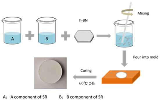
Figure 1.
Illustration of preparation of hexagonal boron nitride and silicone rubber (h-BN/SR) composite.
2.3. Characterization
Drying oven (DHG-9070G, Shanghai Jinghong Experimental Equipment Co., Ltd.) was applied to the hardening of SR. Fourier-transform infrared spectroscopy (FTIR spectroscopy, Nicolet 5700) was used to characterize the chemical compositions of samples with a scanning range of 500–4000 cm−1. The samples were cut into thin slices with a knife blade before FTIR test. Thermogravimetric analysis (TGA4000, PE) was performed in a protective atmosphere of Ar gas at a temperature rise rate of 10 °C/min. The crystal structures of the SR, h-BN, and h-BN/SR were tested by ray diffraction (XRD, D8 ADVANCE Bruker). A scanning electron microscope (SEM, JEOL, JSM-6701F) was used to examine the microscopic structures of these specimens. The stress strength testing was performed with a tensile machine (SUNS, CMT4304) by accuracy of ±1%. The dielectric constant and dielectric loss were analyzed using a dielectric performance machine (Waykerr, 6500B). The thermal conductivity properties of the prepared SR and h-BN/SR composite samples were tested with a thermal conductivity measurement instrument (XIATECH, TC3000, accuracy: ±1.5%) at room temperature. The value of the thermal conductivity was obtained by three test samples, and each sample was tested three times, averaged and the minimum average was selected. The compression test is to test two samples, taking the minimum value. The sample size for compressive strength and thermal conductivity testing is φ40 × 10 mm, and the samples size for the dielectric constant test is φ40 × 2 mm.
2.4. Battery Thermal Management Simulation
The BTM simulations were conducted using the COMSOL 5.4 commercial software. The battery is the heat source, and the liquid-cooling aluminum plate is the heat sink. To analyze the interface thermal resistance effect on battery temperature, different interface gaps (10, 20, and 50 μm) are simulated, and the schematic of the numerical model is shown in Figure 2.
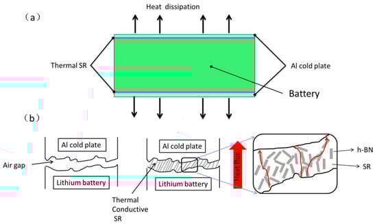
Figure 2.
(a) Structural model of battery thermal management simulation; (b) interface between battery and aluminum cold plate.
3. SR, h-BN, and h-BN/SR Composite Characteristics
3.1. Crystal Morphology
The crystal morphology of the composite material was analyzed by XRD, as shown in Figure 3. Pure SR has an amorphous structure with a steamed-bun-like peak at about 11.9°, with no other peaks, indicating that SR is amorphous with long-range disorder and short-range order. When the additive proportion is 30 wt% of BN, the composite material has diffraction peaks at 26.9°, 41.6°, 43.8°, 50.0°, and 55.0°, which correspond to the (002), (100), (101), (102), and (104) crystal planes of h-BN, respectively [23]. The addition of 10 wt% h-BN/SR shows an obvious diffraction peak at 26.9°, and the other peaks of the h-BN are not obvious. This is because the content of h-BN in the silicone rubber matrix is low. For 30 wt% samples, the intensity ratio of I(002) to I(001) of h-BN diffraction peaks is decreased as compared to pristine h-BN. It is demonstrated that the h-BN has a certain orientation in the silicone rubber body due to the rapid stirring in the synthesis process. The orientation distribution of boron nitride in the matrix can improve the thermal conductivity of the composite material [24]. XRD analysis shows that there is no change of the crystal structure of paraffin wax and hexagonal boron nitride in the composite.
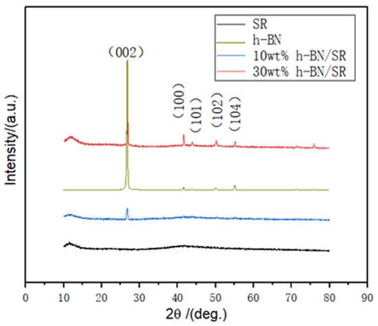
Figure 3.
XRD spectra of h-BN, SR, and h-BN/SR composite.
3.2. Chemical Structure Analysis
Figure 4 shows the FTIR maps of h-BN, SR, and h-BN/SR. The h-BN has significant absorption peaks near 808 cm−1 and 1361 cm−1, corresponding to stretching vibration (out-of-plane vibration, A2u mode) and bending vibration (in-plane vibration, E1u mode) [25]. For pure SR, the two vibration peaks at 1017 cm−1, and 1088 cm−1 belong to the characteristic skeleton (Si-O-Si) absorption peaks, while the peaks at 808 cm−1 and 2962 cm−1 belong to the Si-CH3 groups [26]. In the composite material, the peaks of the h-BN and SR both exist, indicating that the mixing of SR and h-BN is physical, which is consistent with the XRD analysis results. Physical mixing is thus beneficial for the h-BN/SR composite to maintain the inherent characteristics of the SR.
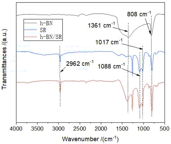
Figure 4.
FTIR curves of h-BN, SR, and h-BN/SR.
3.3. Microscopic Analysis
The microstructure of h-BN is shown in Figure 5a. The h-BN has a flake-shaped structure with a lateral size of ∼1−3 μm, and the h-BN fine particles are prone to aggregation and stacking. Figure 5b shows the SEM image of h-BN/SR with a h-BN content of 30 wt%. The cross section consists of two parts, namely the SR matrix and h-BN particles. The SR matrix is smooth without defects, such as pores, and the h-BN particles are randomly but uniformly embedded in the SR matrix, which is beneficial for improving the mechanics of the composite SR performance. To further certify the homogeneous dispersion of h-BN in the SR matrix, the SR composite was analyzed using the element map. Figure 5c is the SEM image of h-BN/SR, while Figure 5d–f are the corresponding B, N, and Si element diagrams. It is seen that the B, N, and Si are moderately distributed in the h-BN/SR composite without aggregation. The uniform dispersion of h-BN in the SR body facilitates an improvement in heat conductivity.
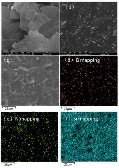
Figure 5.
SEM images: (a) morphology of h-BN, (b,c) morphologies of h-BN/SR composite with different magnifications, and (d–f) corresponding B, N, and Si element mappings.
3.4. Thermal Conductivity
Experimental and theoretical heat conductivities of the h-BN/SR composite are shown in Figure 6, revealing that pure SR has a relatively low thermal conductivity of only 0.17 W/m∙K. With the increasing loading of the h-BN thermally conductive particles, the thermal conductivity of the composite SR increases owing to h-BN having a much higher thermal conductivity compared to the SR matrix. When the filling proportion is 30 wt%, the thermal conductivity of the composite material reaches 0.58 W/m∙K, which is 3.4 times that of pure SR. The thermal conductivity of the composite material was calculated by the Maxwell–Eucken [27] and Lewis–Nielsen [28] models, which are commonly applied to analyze the thermal conductivities of binary composite materials [27]. Equations (1) and (2) correspond to Maxwell–Eucken and Lewis–Nielsen model, respectively. The equations are as follows:
where λc, λm and λp are the heat conductivity of composite, polymer material and particles, Vp is volumetric fraction filler particles. In Equation (2), A = kE − 1 is related to the shape factor of the filler particles, and kE is the Einstein coefficient. With a more irregular shape of the composite filler, the value of A is bigger than 2 [29]. In this study, the value of A is 8, which is used to fit the curve. By comparison, it was found that the experimental test values were higher than the Maxwell–Eucken model calculation values. This is because h-BN is flake-like and has anisotropy, while the Maxwell-Eucken model is mainly suitable for thermally conductive fillers with regularly spherical shapes. However, the Lewis–Nielsen model has a good agreement with the experiment. Under equal volume fraction filling, the thermal conductivity of h-BN/SR in this study is close to the h-BN@SR composite researched by other studies [24,30], and higher than that of Al2O3@SR composite in Reference [4]. This is because h-BN was moderately dispersed in the SR matrix, which greatly improved the thermal conductivity of the h-BN/SR composite. Furthermore, to verify the repeatability, based on the three samples tested, the experimental errors were calculated using the standard deviation approach. It can be seen that the standard deviation is less than 1%, indicating that the product has good consistency.
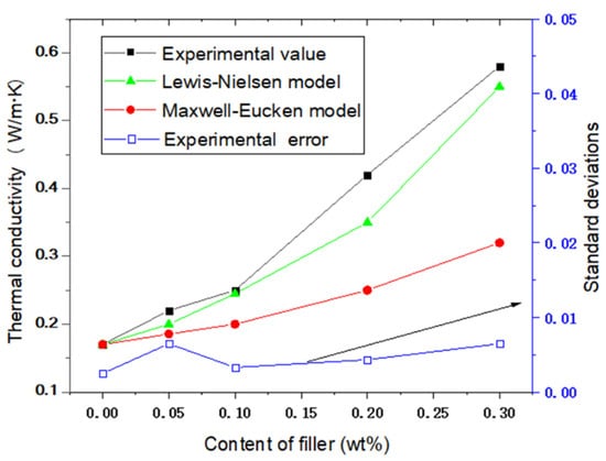
Figure 6.
Thermal conductivities of SR and h-BN/SR composite.
3.5. Thermal Stability Analysis
Figure 7 shows the TGA curves of h-BN, SR, and h-BN/SR composite. The h-BN sample exhibits good thermal stability. As the temperature of heating is increased to 700 °C, there is no obvious weight loss of h-BN. The thermal decomposition of pure SR reaches 368 °C, and the decomposition of SR can be classified into two processes. First, the side chain C-H is broken down; then, the main chain Si-O-Si begins breaking down because of the Si-O-Si bond that has a stronger bond energy of up to 462 kJ/mol [31]. The onset decomposition temperature of the h-BN/SR composite is 394 °C, which is 26 °C higher than that of pure SR, indicating that the presence of h-BN can increase the thermal decomposition temperature of SR. The excellent thermal stability thus ensures that the h-BN/SR composite can be used in high-temperature applications.
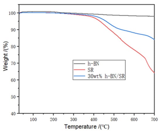
Figure 7.
TGA curves of h-BN, SR, and h-BN/SR composite.
3.6. Compression Performance Test
The compressive strength of SR and h-BN/SR is presented in Figure 8. The compressive strength of the h-BN/SR composite increased by the addition of h-BN fine particles, and the compressive strengths of pure SR, 10 wt% h-BN/SR, 20 wt% h-BN/SR and 30 wt% h-BN/SR composite are 0.63, 1.49, 2.21 and 4.27 MPa, respectively. Therefore, the maximum compressive strength, which is almost 6.7 times that of pure SR, is obtained with SR composites filled with 30 wt% h-BN. Furthermore, an increase in the h-BN resulted in enhancement of the fracture strain. When the filling amount is 30 wt%, the fracture strain of h-BN/SR is as high as 0.78, while the pure SR fracture strain is 0.61. The prepared composite silicone rubber thus has good compressive strength and toughness. This result is attributed to adequate dispersion of the h-BN in the SR matrix, with fewer defects as well as the good mechanical properties of h-BN.
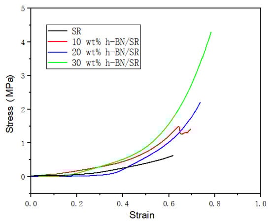
Figure 8.
Compressive strength of SR composite filled with different mass percent of h-BN particles.
3.7. Dielectric Performance Test
It can be seen from Figure 9a that pure SR has a low dielectric constant. The dielectric constant value of pure SR is 1.69 at 1 MHz. Compared with pure SR, the h-BN/SR composite has a higher dielectric constant, which increases with the loading of the h-BN content. This is mainly because the h-BN itself has a higher dielectric constant (ε = 4) and polarization effect on the interface between SR and h-BN [30]. It also can be seen that the curves of all samples are smooth across the entire frequency domain (10–106 Hz), indicating that the polarization in the composite material can quickly respond to changes in the electric field frequency [4]. The experimental values of the dielectric loss tangent of the h-BN/SR composite are shown in Figure 9b. The dielectric loss tangent of the h-BN/SR composite increased with increasing content of the h-BN filler. This is because the composite material contains more conductive carriers compared with pure SR, which causes improvement of the dielectric loss of the h-BN/SR composite. Although the addition of h-BN increases the dielectric loss tangent of the composite material, this value is still low. At 1 MHz, when the h-BN filling amount is 30 wt% of the composite SR, the dielectric loss tangent is only 0.02, indicating that the composite material has good dielectric stability.
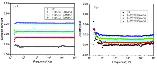
Figure 9.
Electrical properties of SR and h-BN/SR composite: (a) dielectric constant; (b) dielectric loss.
4. Battery Thermal Management Simulation
4.1. Heating Model of Lithium Battery
There are many methods to simulate the heat release in lithium batteries, including the electrochemical-thermal coupling model [32], equivalent circuit model [33], and Bernardi model [34]. Compared to the electrochemical-thermal coupling model, the Bernardi model has advantages of lower calculation time as well as simple model equation and parameters, which are commonly used to simulate the heat of constant current discharge of the battery. The Bernardi model equation can be expressed as follows:
In Equation (1), is the rate of heat release, which is composed of two parts, namely irreversible heat caused by Joule heating and reversible heat generated by entropy changes during the electrochemical reaction; I, V, Eoc, and U are the current, volume, open circuit voltage, and operating voltage of the battery, respectively. Tamb is the ambient temperature (K), which was considered as 293.15 K in this work, and is the entropy heat coefficient of the battery. In this study, the value of is 0.135 mV·K−1, according to Reference [19]. The irreversible heat is calculated as follows:
where R is the internal resistance (mΩ) whose value is the function of the battery capacity (state-of-charge; SOC). The value used in this study was referenced from literature [35], as shown in Figure 10.
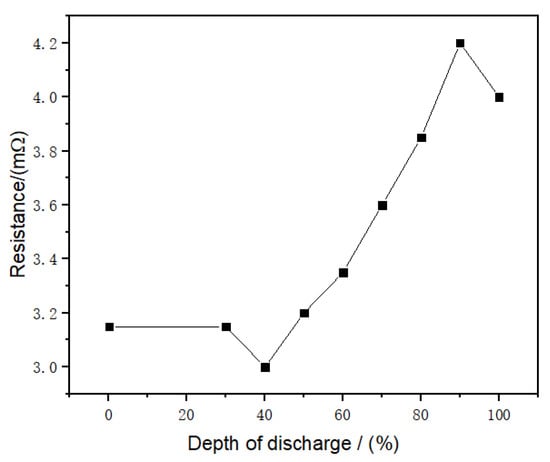
Figure 10.
Relationship between battery internal resistance and depth of discharge [35].
When the lithium battery is discharged with a constant current, the relationship between battery SOC and time is
In the formula, I is the battery current (A), t is the time (s), and C is the battery capacity (Ah). Therefore, given the discharge current I, entropy thermal coefficient, and battery internal resistance R, the heat source can be obtained by Equation (1). According to the heating rate of the battery, its surface temperature can be determined from the following two expressions:
In these equations, the parameters ρ, Cp, T, and λ correspond to the battery density, heat capacity, temperature, and thermal conductivity, respectively. The h is the heat transfer coefficient. In this work, the simulated capacity of the prismatic battery is 20 Ah, and the material parameters are referred to from the literature [35], as summarized in Table 1 below.

Table 1.
Material parameters of the battery and Al cold plate.
4.2. Grid Independence Verification
The commercial software COMSOL was used to simulate the battery heating. The battery is discharged at a constant current rate of 3C. The conditions are natural convection cooling in air with a typical value of the heat transfer coefficient h = 5 W/(m2·K). To verify that the grid size is independent of the numerical simulation results, the battery temperature was calculated at different grid sizes. As shown in Figure 11, different grids sizes have almost no effects on the battery temperature, and the three curves overlap during the entire discharge period. Therefore, to reduce the computational time, a coarse grid was used in the subsequent analysis. Moreover, in the battery temperature curve, the maximum value is 67.6 °C under a 3C discharge current rate, which exceeds the battery safety limit of 50 °C [34]. Therefore, it is concluded that natural cooling cannot effectively reduce battery temperature and that thermal management of the battery is required.
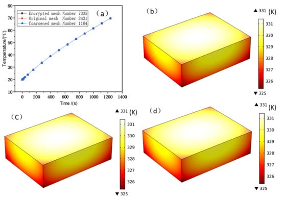
Figure 11.
(a) Temperature curves of the battery body under different mesh densities; (b–d) temperature contours of the battery under encrypted, original, and coarsened meshes, respectively.
4.3. Battery Thermal Management System with h-BN/SR Composite
For BTM, water is a more suitable coolant than air because liquid cooling with water has a larger specific heat capacity than air. Studies have shown that air cooling is equivalent to a battery surface heat transfer coefficient of 50 W/(m2·K), while forced liquid cooling is equivalent to a battery surface convective heat transfer coefficient of 100 or 150 W/(m2·K) [36]; therefore, in this study, the surface heat transfer coefficient of the liquid-cooled aluminum plate is considered as 150 W/(m2·K), which is equivalent to the cooling effect with a liquid-cooled plate. To simulate the thermal contact resistance, the equivalent interface thermal resistance model was adopted in this study because of its simple model [37]. The equation of this model is given in Equation (8)
where k is the thermal conductivity of the gap material, for example air or SR, δ is the gap thickness, and hg is the gap conductance. In this study, different values of the gap thickness (10 μm, 20 μm, and 50 μm) were considered. The thermal conductivity of the h-BN/SR composite was 0.58 W/m∙K based on the actual measured value. Figure 12a depicts the battery temperature curve under a battery discharge rate of 3C. It can be seen that the battery temperature is lowest under ideal contact (no gap contact). After the 3C discharge is complete, the battery temperature is 33.9 °C. When the gap increases, the battery temperature also increases. In the case of a gap of 50 μm, the battery temperature reached the highest value of 35.9 °C, which is 2 °C higher than that of the no gap contact condition; this clearly illustrates that the interface gap decreases the heat dissipation efficiency of the liquid-cooled aluminum plate. When h-BN/SR is used as filler in the gap, the highest battery temperatures obtained are 34.0 °C (10 μm), 34.05 °C (20 μm), and 34.1 °C (50 μm), which is very close to the no gap contact condition value of 33.9 °C and lower than that for gap contact without the h-BN/SR filler. Figure 12b displays the temperature curve of the battery discharged at a rate of 4C. The highest temperature of the battery without gap contact is thus 43.1 °C after the discharge is complete. Similar to the 3C rate of discharge with increased interface gap, the battery temperature increased in this case. At gaps of 10 μm, 20 μm, and 50 μm, the highest temperatures of the battery were 43.8 °C, 44.5 °C, and 46.2 °C, respectively. When the gap is filled with conductive SR, the maximum temperatures of the battery are 43.2 °C (10 μm), 43.23 °C (20 μm), and 43.3 °C (50 μm), which are 0.6 °C (10 μm), 1.27 °C (20 μm), and 2.9 °C (50 μm) lower than those without the thermally conductive SR, respectively. This shows that the thermally conductive SR can significantly decrease the interface thermal resistance, enhance the cooling effect, and improve the safety performance of the battery. Figure 13 shows the simulation model and temperature profile of the battery at the end of the 4C discharge rate. From the temperature profile, it is noted that the highest temperature of the battery is at the center position because the center of the battery is farthest from the liquid-cooled aluminum plate.
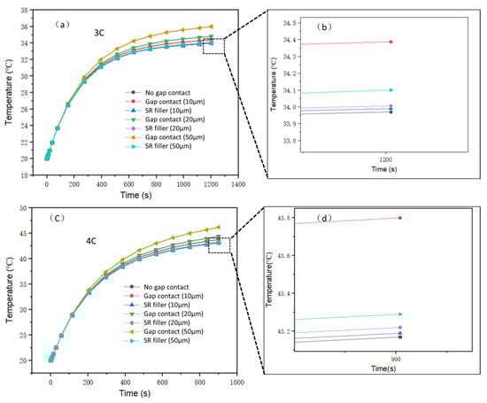
Figure 12.
Maximum temperature curves of battery under different contact types: (a) 3C discharge; (b) 3C discharge local enlarged graph; (c) 4C discharge; (d) 4C discharge local enlarged graph.
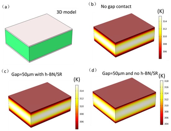
Figure 13.
(a) 3D model of the battery and liquid-cooling aluminum plate, (b–d) temperature cloud charts of the battery and liquid-cooled aluminum plate under battery discharge of 4C, corresponding to ideal contact without gap, with gap contact (50 μm), and without SR filling (50 μm), respectively.
5. Conclusions
The h-BN/SR composite material was synthesized by a convenient mechanical stirring method, and its crystal structure, chemical composition, and microscopic structure were characterized by XRD, FTIR spectroscopy, and SEM, respectively. The material thermal stability, thermal conductivity, and mechanical properties were measured. The application of composite SR was then simulated by the finite element method, and the following results were noted:
- (1)
- FTIR and XRD analyses showed that the h-BN and SR were physically mixed and that no chemical reactions occurred. The SEM analysis showed that the h-BN had good dispersion in SR without agglomeration, which is beneficial for improving the thermal conductivity of the composite.
- (2)
- When the weight proportion of boron nitride is 30 wt%, the thermal conductivity is 0.58 W/m∙K, which is 3.4 times that of pure SR, and the strength is 4.27 MPa, which is 6.7 times that of pure SR. The composite material also has low dielectric constant and dielectric loss, and it is suitable for electronic packaging applications.
- (3)
- The BTM simulation shows that when the interface is filled with the h-BN/SR composite, the maximum temperature of the battery decreased for different discharge rates. When the battery was discharged at a constant current rate of 4C, the use of the thermally conductive h-BN/SR composite material decreased the maximum temperature of the battery by 0.6 °C, 1.27 °C, and 2.9 °C for interface gaps of 10 μm, 20 μm, and 50 μm, respectively.
Author Contributions
Supervision, J.H.; Writing—original draft, Y.Z.; Writing—review & editing, M.C., G.D., Z.L. and W.L. All authors have read and agreed to the published version of the manuscript.
Funding
This research was funded by the National Natural Science Foundation of China grant number (51762034) and the APC was funded by the National Natural Science Foundation of China grant number (51762034).
Institutional Review Board Statement
Not Applicable.
Informed Consent Statement
Not Applicable.
Data Availability Statement
Data Sharing Not Applicable. No new data were created or analyzed in this study. Data sharing is not applicable to this article.
Acknowledgments
This work was supported by a grant from the National Natural Science Foundation of China (Grant No. 51762034).
Conflicts of Interest
The authors declare no conflict of interest.
References
- Razeeb, K.M.; Dalton, E.; Cross, G.L.W.; Robinson, A.J. Present and future thermal interface materials for electronic devices. Int. Mater. Rev 2018, 63, 1–21. [Google Scholar] [CrossRef]
- Hansson, J.; Nilsson, T.M.J.; Ye, L.; Liu, J. Novel nanostructured thermal interface materials: A review. Int. Mater. Rev. 2017, 63, 22–45. [Google Scholar] [CrossRef]
- Ji, T.; Zhang, L.-Q.; Wang, W.-C.; Liu, Y.; Zhang, X.-F.; Lu, Y.-L. Cold plasma modification of boron nitride fillers and its effect on the thermal conductivity of silicone rubber/boron nitride composites. Polym. Compos. 2012, 33, 1473–1481. [Google Scholar] [CrossRef]
- Yang, D.; Huang, S.; Ruan, M.; Li, S.; Yang, J.; Wu, Y.; Guo, W.; Zhang, L. Mussel Inspired Modification for Aluminum Oxide/Silicone Elastomer Composites with Largely Improved Thermal Conductivity and Low Dielectric Constant. Ind. Eng. Chem. Res. 2018, 57, 3255–3262. [Google Scholar] [CrossRef]
- Wu, W.; Chen, Z. A novel phase-change composites based on silicone rubber containing energy-storage microcapsules. J. Therm. Anal. Calorim. 2018, 133, 1365–1370. [Google Scholar] [CrossRef]
- Chiu, H.T.; Sukachonmakul, T.; Kuo, M.T.; Wang, Y.H.; Wattanakul, K. Surface modification of aluminum nitride by polysilazane and its polymer-derived amorphous silicon oxycarbide ceramic for the enhancement of thermal conductivity in silicone rubber composite. Appl. Surf. Sci. 2014, 292, 928–936. [Google Scholar] [CrossRef]
- Cui, W.; Zhu, Y.; Yuan, X.; Chen, K.; Kang, F. Gel-cast-foam-assisted combustion synthesis of elongated β-Si3N4 crystals and their effects on improving the thermal conductivity of silicone composites. J. Alloys Compd. 2012, 540, 165–169. [Google Scholar] [CrossRef]
- Kong, K.T.S.; Mariatti, M.; Rashid, A.A.; Busfield, J.J.C. Effect of processing methods and functional groups on the properties of multi-walled carbon nanotube filled poly(dimethyl siloxane) composites. Polym. Bull. 2012, 69, 937–953. [Google Scholar] [CrossRef]
- Hong, J.; Lee, J.; Hong, C.K.; Shim, S.E. Effect of dispersion state of carbon nanotube on the thermal conductivity of poly(dimethyl siloxane) composites. Curr. Appl. Phys. 2010, 10, 359–363. [Google Scholar] [CrossRef]
- Shahil, K.M.; Balandin, A.A. Graphene-multilayer graphene nanocomposites as highly efficient thermal interface materials. Nano Lett. 2012, 12, 861–867. [Google Scholar] [CrossRef]
- Song, Y.; Yu, J.; Yu, L.; Alam, F.E.; Dai, W.; Li, C.; Jiang, N. Enhancing the thermal, electrical, and mechanical properties of silicone rubber by addition of graphene nanoplatelets. Mater. Des. 2015, 88, 950–957. [Google Scholar] [CrossRef]
- Shen, H.; Guo, J.; Wang, H.; Zhao, N.; Xu, J. Bioinspired Modification of h-BN for High Thermal Conductive Composite Films with Aligned Structure. ACS Appl. Mater. Interfaces 2015, 7, 5701–5708. [Google Scholar] [CrossRef]
- Li, D.; Zeng, D.; Chen, Q.; Wei, M.; Song, L.; Xiao, C.; Pan, D. Effect of different size complex fillers on thermal conductivity of PA6 thermal composites. Plast. Rubber Compos. 2019, 48, 347–355. [Google Scholar] [CrossRef]
- Wang, L.; Han, D.; Luo, J.; Li, T.; Lin, Z.; Yao, Y. Highly Efficient Growth of Boron Nitride Nanotubes and the Thermal Conductivity of Their Polymer Composites. J. Phys. Chem. C 2018, 122, 1867–1873. [Google Scholar] [CrossRef]
- Liu, Z.; Song, L.; Zhao, S.; Huang, J.; Ma, L.; Zhang, J.; Lou, J.; Ajayan, P.M. Direct growth of graphene/hexagonal boron nitride stacked layers. Nano Lett. 2011, 11, 2032–2037. [Google Scholar] [CrossRef]
- Tang, Z.; Wang, S.; Liu, Z.; Cheng, J. Numerical analysis of temperature uniformity of a liquid cooling battery module composed of heat-conducting blocks with gradient contact surface angles. Appl. Therm. Eng. 2020, 178, 115509. [Google Scholar] [CrossRef]
- Varma Siruvuri, S.D.V.S.S.; Budarapu, P.R. Studies on thermal management of Lithium-ion battery pack using water as the cooling fluid. J. Energy Storage 2020, 29, 101377. [Google Scholar] [CrossRef]
- He, J.; Yang, X.; Zhang, G. A phase change material with enhanced thermal conductivity and secondary heat dissipation capability by introducing a binary thermal conductive skeleton for battery thermal management. Appl. Therm. Eng. 2019, 148, 984–991. [Google Scholar] [CrossRef]
- Patil, M.S.; Seo, J.-H.; Panchal, S.; Jee, S.-W.; Lee, M.-Y. Investigation on thermal performance of water-cooled Li-ion pouch cell and pack at high discharge rate with U-turn type microchannel cold plate. Int. J. Heat Mass Transf. 2020, 155, 119728. [Google Scholar] [CrossRef]
- Lv, Y.; Zhou, D.; Yang, X.; Liu, X.; Li, X.; Zhang, G. Experimental investigation on a novel liquid-cooling strategy by coupling with graphene-modified silica gel for the thermal management of cylindrical battery. Appl. Therm. Eng. 2019, 159, 113885. [Google Scholar] [CrossRef]
- Tran, T.-H.; Harmand, S.; Desmet, B.; Filangi, S. Experimental investigation on the feasibility of heat pipe cooling for HEV/EV lithium-ion battery. Appl. Therm. Eng. 2014, 63, 551–558. [Google Scholar] [CrossRef]
- Wang, C.; Zhang, G.; Meng, L.; Li, X.; Situ, W.; Lv, Y.; Rao, M. Liquid cooling based on thermal silica plate for battery thermal management system. Int. J. Energy Res. 2017, 41, 2468–2479. [Google Scholar] [CrossRef]
- Matović, B.; Luković, J.; Nikolić, M.; Babić, B.; Stanković, N.; Jokić, B.; Jelenković, B. Synthesis and characterization of nanocrystaline hexagonal boron nitride powders: XRD and luminescence properties. Ceram. Int. 2016, 42, 16655–16658. [Google Scholar] [CrossRef]
- Kuang, Z.; Chen, Y.; Lu, Y.; Liu, L.; Hu, S.; Wen, S.; Mao, Y.; Zhang, L. Fabrication of Highly Oriented Hexagonal Boron Nitride Nanosheet/Elastomer Nanocomposites with High Thermal Conductivity. Small 2015, 11, 1655–1659. [Google Scholar] [CrossRef] [PubMed]
- Lee, D.; Lee, B.; Park, K.H.; Ryu, H.J.; Jeon, S.; Hong, S.H. Scalable Exfoliation Process for Highly Soluble Boron Nitride Nanoplatelets by Hydroxide-Assisted Ball Milling. Nano Lett. 2015, 15, 1238–1244. [Google Scholar] [CrossRef]
- Zhang, X.; Li, X.; Zhou, Y.; Hai, C.; Shen, Y.; Ren, X.; Zeng, J. Calcium Chloride Hexahydrate/Diatomite/Paraffin as Composite Shape-Stabilized Phase-Change Material for Thermal Energy Storage. Energy Fuels 2017, 32, 916–921. [Google Scholar] [CrossRef]
- Shtrikman, Z.H.S. A variational approach to the theory of the effective magnetic permeability of multiphase materials. J. Appl. Phys. 1962, 33, 3125–3131. [Google Scholar]
- Pal, R. On the Lewis–Nielsen model for thermal/electrical conductivity of composites. Compos. Part A Appl. Sci. Manuf. 2008, 39, 718–726. [Google Scholar] [CrossRef]
- Nielsen, L.E. Thermal conductivity of particulate-filled polymers. J. Appl. Polym. Sci. 1973, 17, 2. [Google Scholar] [CrossRef]
- Gu, J.; Meng, X.; Tang, Y.; Li, Y.; Zhuang, Q.; Kong, J. Hexagonal boron nitride/polymethyl-vinyl siloxane rubber dielectric thermally conductive composites with ideal thermal stabilities. Compos. Part A Appl. Sci. Manuf. 2017, 92, 27–32. [Google Scholar] [CrossRef]
- Radhakrishnan, T.S. New method for evaluation of kinetic parameters and mechanism of degradation from pyrolysis—GC studies: Thermal degradation of polydimethylsiloxanes. J. Appl. Polym. Sci. 1999, 73, 441–450. [Google Scholar] [CrossRef]
- Mastali, M.; Foreman, E.; Modjtahedi, A.; Samadani, E.; Amirfazli, A.; Farhad, S.; Fraser, R.A.; Fowler, M. Electrochemical-thermal modeling and experimental validation of commercial graphite/LiFePO4 pouch lithium-ion batteries. Int. J. Therm. Sci. 2018, 129, 218–230. [Google Scholar] [CrossRef]
- Hu, Y.; Yurkovich, S.; Guezennec, Y.; Yurkovich, B.J. Electro-thermal battery model identification for automotive applications. J. Power Sources 2011, 196, 449–457. [Google Scholar] [CrossRef]
- Bandhauer, T.M.; Garimella, S.; Fuller, T.F. A Critical Review of Thermal Issues in Lithium-Ion Batteries. J. Electrochem. Soc. 2011, 158, R1. [Google Scholar] [CrossRef]
- Li, H.; Xiao, X.; Wang, Y.; Lian, C.; Li, Q.; Wang, Z. Performance investigation of a battery thermal management system with microencapsulated phase change material suspension. Appl. Therm. Eng. 2020, 180, 115795. [Google Scholar] [CrossRef]
- An, Z.; Jia, L.; Li, X.; Ding, Y. Experimental investigation on lithium-ion battery thermal management based on flow boiling in mini-channel. Appl. Therm. Eng. 2017, 117, 534–543. [Google Scholar] [CrossRef]
- Aghkand, Z.K.; Dil, E.J.; Ajji, A.; Dubois, C. Simulation of Heat Transfer in Heat Sealing of Multilayer Polymeric Films: Effect of Process Parameters and Material Properties. Ind. Eng. Chem. Res. 2018, 57, 14571–14582. [Google Scholar] [CrossRef]
Publisher’s Note: MDPI stays neutral with regard to jurisdictional claims in published maps and institutional affiliations. |
© 2021 by the authors. Licensee MDPI, Basel, Switzerland. This article is an open access article distributed under the terms and conditions of the Creative Commons Attribution (CC BY) license (http://creativecommons.org/licenses/by/4.0/).