1. Introduction
In recent years, there has been considerable attention to the scramjet engine, which is a potential candidate for future hypersonic propulsion vehicles [
1,
2,
3]. The fuel injection system plays a pivotal role in enhancing the fuel–air mixing attributes and improving the overall combustion performance of the scramjet engine. A robust flame holding mechanism is needed owing to the short residence time of airflow in the scramjet combustor. There are various injection and flame holding mechanisms, such as cavities [
4,
5,
6,
7,
8,
9,
10], pylons [
11,
12,
13,
14] and struts [
15,
16,
17,
18,
19,
20,
21,
22,
23,
24,
25,
26,
27,
28]. The combinations of the aforementioned schemes [
29,
30,
31,
32] were succeeded to some extend by several studies. A strut-based injector configuration is among those that could solve the aforesaid issues and also uphold the minimum total pressure loss.
Waidmann et al. [
22] performed a sequence of experimentations on aDLR scramjet combustor with the strut-based hydrogen fuel injection method. The combustion experimentations were executed under different operating conditions, such as pressure and temperature. Oevermann [
33] considered numerical studies on a tw- dimensional (2D) scramjet combustor using the flamelet model and validated the flow parameters with the reported experimental outcomes of DLR [
21,
22]. Followed by Oevermann, many researchers simulated supersonic combustion typically by using the strut injector [
24,
34,
35]. Xue et al. [
36] researched the shock wave emanating from the strut and illustrated that the oblique shock waves generated due to the strut inherently progress the scramjet engine air–fuel mixing and combustion efficiencies too.
The consequence of a straight and tapered strut in a Mach 2.0 flow field was numerically investigated by Rahul and Ashoke [
37] who disclosed that a straight strut provides an effective mixing in the supersonic flow field. The research of Wu et al. examined the 2D and three-dimensional (3D) scramjet combustor model by using the Large Eddy Simulation method wherein the shock wave pattern, shock train pattern and mixing behaviors of turbulent flows at various positions are compared. As a result, the 2D model complied with the 3D simulation results.
The study of Choubey and Pandey [
28] executed a numerical simulation analysis on two-strut configurations in a scramjet combustor model by changing the strut’s angle of attack and asserted that zero angles of attack make a surge in mixing and combustion efficiencies. Researchers in [
35] delt with the effect of altering the strut geometry and orientation in the combustor from the inlet. Further, it is disclosed that the optimum lip height and position of the strut has an essential role towards improving the combustion efficiency. Three-strut positioning in a scramjet combustor was computationally examined by Kumar et al. [
38]. It was identified that the maximum combustion efficiency and thrust was attained by Pareto-optimal optimization studies accordingly positioning the struts in the combustor.
The effect of multistrut and wall injections in a 2D scramjet model was numerically examined by Choubey and Pandey [
39] who determined that multistrut combined with two wall injectors of hydrogen jets provides better air–fuel mixing characteristics when compared with other injection methods. In addition, the hydrogen distribution increases near the combustor wall owing to the combined injection that results in broadening temperature distribution due to the intense combustion occurrence.
The study conducted by Kumaran and Babu [
40] numerically simulated the hydrogen-fueled supersonic combustor employing a multistep chemistry model and compared it with the single-step reaction model to evaluate the performance of the combustor. The study findings disclosed that a multistep chemistry model could be an exercise to evaluate the insight properties of the combustion reaction, such as heat release rate and ignition delay. Conversely, the single-step model can offer better results for the combustor’s overall performance with a decrease in computational cost.
Gerlinger and Bruggemann [
41] studied the mixing of hydrogen jets supplied from a strut injector under cold supersonic airflow conditions. It is indicated that the mixing layer thickness and the total pressure loss increase by increasing the strut lip thickness, which is mainly due to the increased diffusivity of the hydrogen at the outer strut wall and the more robust shock wave formation. Huang et al. [
42] executed numerical simulation studies on hydrogen–air reaction mechanisms and the injection pressure and temperature variations of a strut-based scramjet combustor. Their study proved that shock waves are formed from the strut base that is pushed out of the combustor with the subsonic flow to increase the injection pressures and temperatures.
The effect of strut tip radius, location of the strut from the combustor inlet, and the half-angle of the strut on the combustion performance of the strut-based scramjet combustor were computationally studied by Haung [
43]. A separation regime is enhanced by increasing the strut tip radius due to the shock wave interaction and the extended boundary layer features. The mixing mechanism of the supersonic air–fuel is managed by the sonic region formed by the shock waves generated in between the strut walls, and the combustion efficiency surges monotonically by increasing the combustor length.
Though many related studies have reported the effect of various strut injection configurations, shock–shear layer interactions due to configurations and their performance parameters in the supersonic field of the scramjet combustor, it is still clear that several flow parametric variations need to be explored to achieve flame stability with the intention of optimizing the scramjet performance. Moreover, the numerical results of Huang et al. [
44] revealed that the wall-mounted ramps increase mixing efficiency with minimum internal drag, which motivated the authors to investigate the implication of wall-mounted ramps in a strut-based scramjet combustor. In this context, the current study was undertaken to estimate the performance of the wall-mounted ramps at various axial locations upstream of a strut injector in a reacting supersonic flow field. The Reynolds Averaged Navier-Stokes (RANS) equation with the Shear Stress Transport (SST) k-ω turbulence model and eddy-dissipation model with a single-step reaction mechanism of hydrogen-air combustion was adopted in this study. The results, such as the shock interactions, combustion efficiency and total pressure loss, could facilitate the improvement of the design and development of strut-based injection schemes in a scramjet combustor.
2. Numerical Methods
It is considered that the effective scheme of studying challenging problems is modeling and computer simulation. In most of the cases carrying out experimentations, the whole real statement is obscured. Numerical simulations are used for the optimization of scramjet combustion [
45]. The computational study of the strut-based scramjet combustor model is performed using ANSYS FLUENT commercial software. In this study, the two-dimensional compressible Reynolds Averaged Navier Stokes (RANS) equation along with a density-based double precision solver was used to resolve the governing equations [
16]. The significance of the RANS equation is that it is capable of providing accurate results even with coarse meshes and resolves the steady flow equations much more easily than other models [
46]. Though LES, DES and DNS numerical schemes [
47] provide precise results for mixing and combustion in scramjet combustors, these methods cannot be used with a coarse mesh as it consumes a lot of computational resources. The model transport equation called the Shear Stress Transport (SST)
k-ω model [
15,
48,
49] with default constants was used for solving the turbulent flow field. The SST
k-
ω turbulence model provides a good prediction of mixing layers and jet flows [
18,
19,
29]. The flow is considered to be ideal gas, and the thermal conductivity and viscosity are computed using mass-weighted-mixing-law. The specific heat constant (Cp) is estimated using mixing law and the gas constant by kinetic theory. A second-order upwind scheme (SOU) is employed for spatial discretization along with a flux vector splitting scheme called the advection upstream splitting method (AUSM) employed to quicken the convergence speed [
25,
50]. The Courant-Friedrichs-Levy (CFL) number is chosen as 0.5 under a suitable relation factor to ensure stability [
51]. The governing equations, i.e., mass, momentum and energy, are stated as:
The Turbulence Model [
52]
The turbulence kinetic energy,
k, and the specific dissipation rate,
ω, are obtained from the following transport equations:
and
The terms, Gk denotes the production of turbulent kinetic energy; Gω is the generation of ω; Γk and Γω signify the effective diffusivity of k and ω, respectively; Yk and Yω express the dissipation of k and ω due to turbulence; Dω symbolizes the cross-diffusion terms; and Sk and Sω are the user-defined source terms.
The effective diffusivities of the SST
k-ω model are given by
where σ
k and σ
ω are the turbulent Prandtl numbers for
k and ω, respectively. The turbulent viscosity,
μt is computed as follows:
where
S is the strain rate magnitude and
The coefficient
α* damps the turbulent viscosity causing a low-Reynolds number correction. It is given by
The blending functions,
F1 and
F2, are given by
where
y is the distance to the next surface and
is the positive portion of the cross-diffusion term
Model constants [
51]:
α1 = 0.31, σ
k,1 = 1.176, σ
ω,1 = 2.0, σ
k,2 =1.0, σ
ω,2 = 1.168.
Species transport equation and further details are in reference [
53]
2.1. Combustion Modeling
The species transport equation and the eddy-dissipation model are employed in the numerical simulation of supersonic combustion studies. The eddy-dissipation model [
54] has been used to solve the turbulence–chemistry interaction and agrees with the experimental data. A single step hydrogen–air reaction mechanism offers better results in providing the overall combustor performance parameters than a multistep model [
40]. In this study, a single-step hydrogen–air reaction was considered to find the overall performance parameters with reduced computational cost, and the reaction equation is as follows:
The solutions may be regarded as converged when the residuals reach their minimum values after declining for more than three orders of magnitude, and the variation between the measured inflow and the outflow mass flux is expected to fall below 0.001 kg/s (less than 0.1% of the fuel flow rate).
2.2. Numerical Setup
2.2.1. Computational Domain
The geometric dimension of the DLR scramjet combustor model examined by Waidmann et al. [
21,
22] is shown in
Figure 1. The incoming air into the combustor is at M = 2.0, whereas the hydrogen is issued at sonic velocity from the strut base parallel to the flow direction. The combustor inlet is 40 × 50 mm in the cross-section up to a length of 100 mm, and consequently, the upper wall is diverged by an angle of 30 till the combustor exit. The strut is located at the center of the combustor radial to the direction of flow (Y = 25 mm) and 77 mm from the combustor’s inlet. The strut is 32 mm in length and has a half divergence angle of 60. The hydrogen is injected from the base of the strut through 15 orifices of 1 mm in diameter. The experimental details of the DLR scramjet model are obtainable in [
21,
22]. The operating parameters are chosen by Waidmann et al. In [
21,
22], the baseline model is described. In the present investigation, two ramps were located symmetrically at the combustor’s top and bottom walls at three axial locations upstream of the strut injector. The flow characteristics of the ramp and strut injectors were compared with the baseline model. The baseline model is represented as Case 1, and the ramps located at 77, 50 and 34 mm from the combustor inlet are designated as Case 2, Case 3 and Case 4, correspondingly. The operating parameters of the scramjet engine are indistinguishable for all the cases.
2.2.2. Boundary Condition
The boundary and initial conditions influence the solution to computational fluid dynamics problems. The incoming supersonic air enters the isolator at Mach 2.0, whereas the hydrogen jet is injected from the strut at the sonic velocity. The boundary conditions at the inlet and outlet of the combustor are given in
Table 1. The air and fuels at the inlet to the combustor are defined using the Dirichlet boundary condition and the domain’s outflow using the Neumann boundary condition. The inlet, outlet and walls of the domain are summarized as follows:
Inlet:
The combustor inlet flow conditions of air and fuel are [
21,
22]
The turbulent kinetic energy,
where
is the average flow velocity at the inlet, and
I is the turbulence intensity. In this study,
I is considered to be 10% [
53].
The specific dissipation rate is
, where
Cμ is the empirical constant for the turbulence model, which is taken as 0.09 [
15], and
is the hydraulic diameter of the combustor.
Walls:
A no-slip condition is chosen for the walls of the computational domain, i.e.,
Outlet:
At the outlet of the computational domain, the pressure outlet boundary condition is stated. Since the flow is supersonic, all the physical variables are extrapolated from the internal cells [
55].
2.2.3. Grid Generation
An unstructured grid is employed in this analysis to resolve the flow field of the strut injector in the supersonic combustor. Three different grids are employed to optimize the grid resolution, so the quality of the numerical results is enhanced by reducing the computing cost and time. Grid sizes, namely, coarse mesh (146,146), medium mesh (191,607) and fine mesh (290,112), are considered for grid convergence analysis. The y+ value is less than 1.0 (6.1 × 10
−7) for the entire flow field, and it corresponds to the first-row cell height specified at 0.001 mm. The grid independence study is shown in
Figure 2. It is found from the convergence analysis that the static pressure values provide a variance of less than 1% for all the mesh sizes. Hence, no further error analysis is required to show grid convergence. Furthermore, downstream of the strut, the medium and fine meshes give almost the same profile. So, the medium-sized mesh is considered to reduce the computational time.
2.3. Validation
The current numerical analysis is corroborated with the DLR test outcomes, which are documented by Waidmann et al. [
21,
22], as shown in
Figure 3 and
Figure 4. It is illustrated that the shock induced by the strut and the reflected shock waves from the walls and the distribution of wall static pressures are in good agreement with the experimental results. The simulation findings of the wall static pressure along the axis are well-matched with the experiment translator, except for a subtle variation caused by the unforeseen turbulence vortices near the wall. In the centerline velocity profile of combustor, Y = 25 mm, the predicted numerical values by Oeverman [
33] and Huang [
43] are included for comparison. In the velocity profile, a strong deceleration of the fuel stream is noticed in the combustion zone where the shock shear layer interfaces. The acceleration of the flow is seen downstream of the combustion region, and an almost uniform profile is perceived downstream of the combustor around X = 180 mm with a slight reduction in the velocity. The numerical simulation results agree with the references [
33,
43] and are in qualitative agreement with the experimental values. However, a strong acceleration downstream and lower velocity values are achieved by this computation.
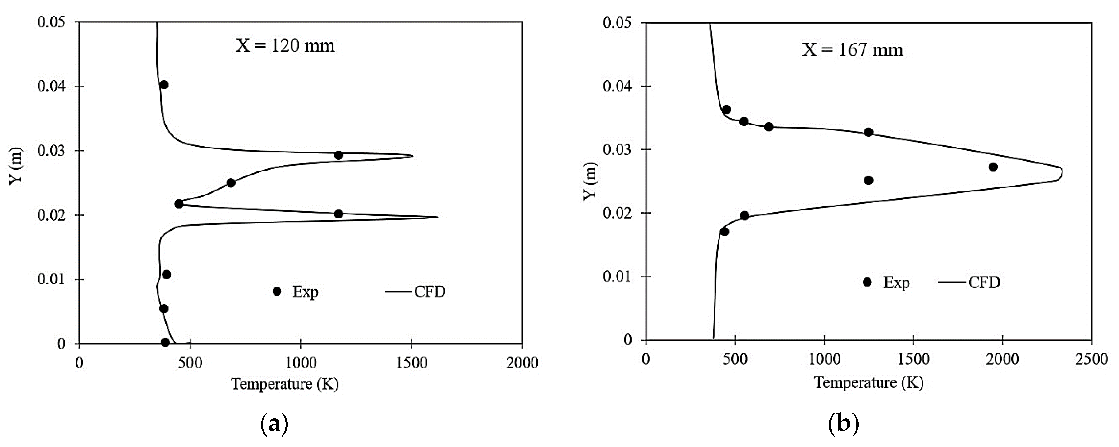
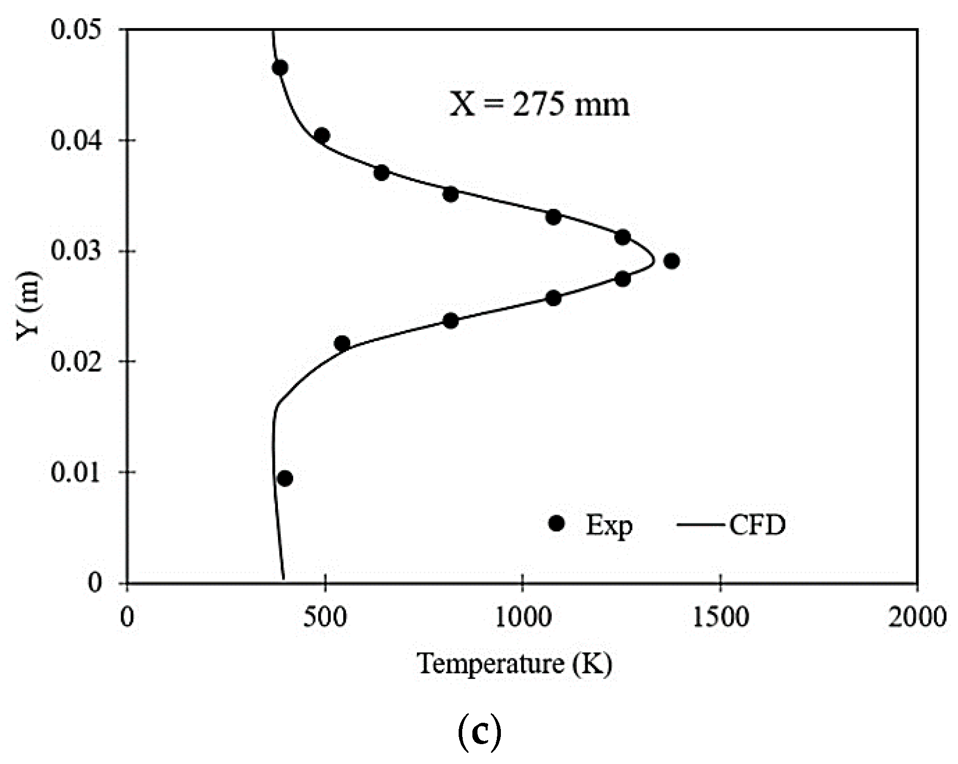
Figure 5 depicts the static temperature profiles of the computational results compared with the reported experimental data at various cross-stream locations X, namely, X = 120, 167 and 275 mm. At X = 167 mm, one high-temperature value is observed by the CFD results due to the intense combustion that occurs at the shock shear layer interaction, and constriction of combustion occurs downstream of this location, and the other predicted values are almost in line with the experimental findings. Moreover, the present two-dimensional model could not predict the three-dimensional shocks from the edges of the strut, the corner effects of the duct and the three-dimensional mixing mechanism, which may deviate the results from the experimental data. For other cross-stream locations X = 120 and 275 mm, the static temperature values of CFD results are in good agreement with the reported investigational data. From the above explanations, it is evident that the paper’s numerical approach is able to investigate the reacting flow studies of the strut-based scramjet combustor.
3. Results and Discussion
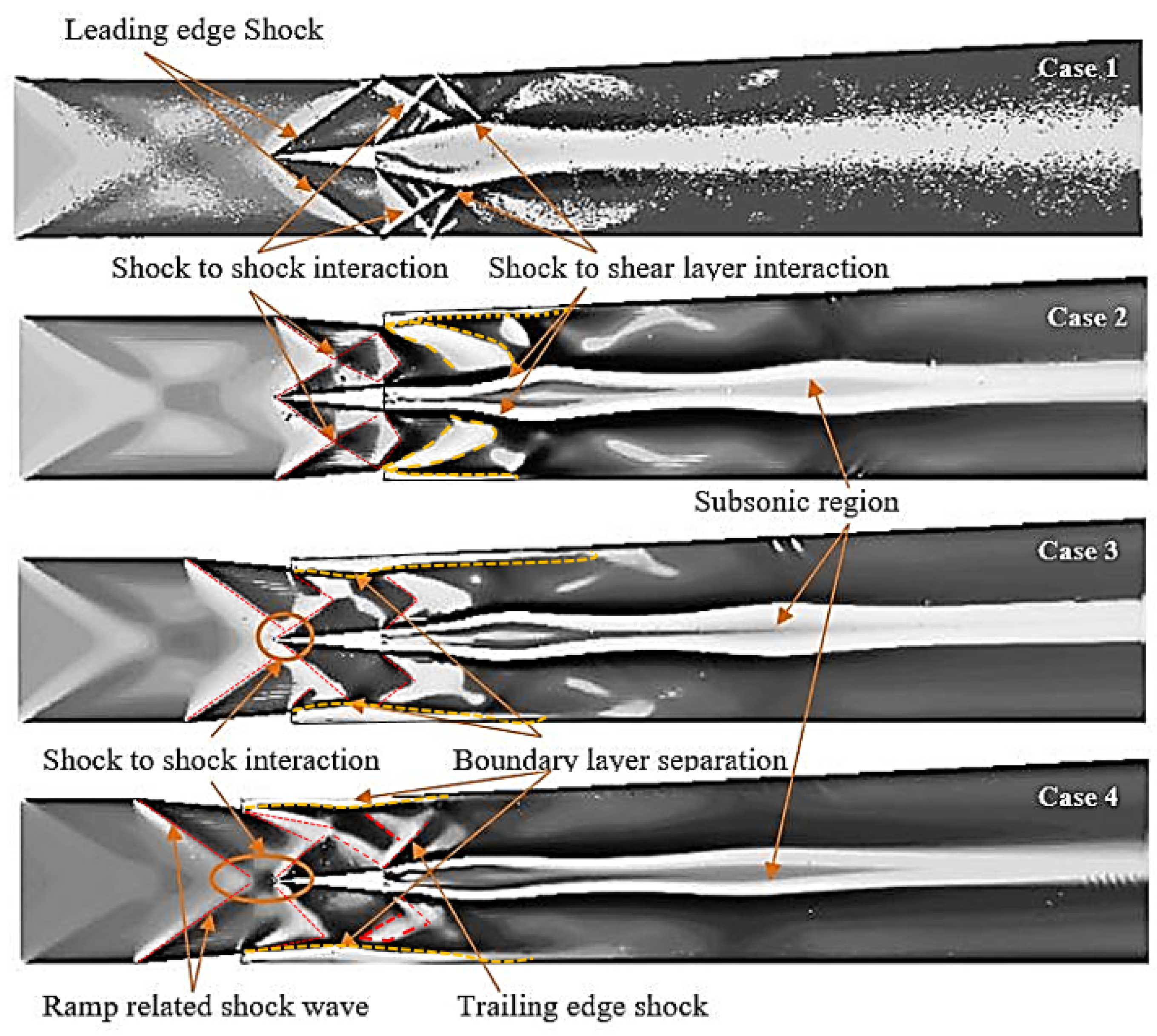
The computational study on the DLR scramjet model with double ramps at different axial locations in a DLR scramjet combustor of identical operating conditions is discussed in the subsequent section. The numerical shadowgraph images of the various cases are shown in
Figure 6. From the DLR scramjet model, Case 1, it is observed that oblique shocks are generated at the leading and trailing edges of the strut and the reflection of shock waves from the internal walls of the combustor. Additionally, the reflected shock interacts with the trailing edge shocks and with the fuel stream shear layers, which enhance the mixing of the streams. The fuel stream shear layer thickness increased due to shock to shear layer interactions on both sides of the fuel stream at the subsonic region and enhanced the combustion regime of the fuel–air stream. For Case 2, the shock wave generated from the leading edge of the top and bottom wall of the ramps interacts with both sides of the strut’s leading-edge shock waves.
Moreover, boundary layer separation is observed downstream of the ramps. The shocks are generated from the trailing edges of the ramps, and the shocks from the boundary layer reattachment region impinge on the fuel jet stream. The shocks are generated due to boundary layer separation at the trailing edge of the ramp, which impinges on the fuel jet stream. This impingement occurs slightly downstream from the fuel injection location compared to Case 1. Additionally, the flow decelerates downstream of shock interaction; thus, the fuel distribution in the spatial direction increases more than in Case 1. For Case 3, it is seen that shock-to-shock interaction occurs at the tip of the strut. The oblique shock from the leading edge of the strut interacts with the shear layer generated from the trailing edge of the ramp, which surges the boundary layer separation. More shock reflections are observed downstream of the strut that further decelerated the supersonic flow. The shock–fuel stream shear layer interactions are observed downstream of the ramps, similar to Case 2 with less intensity. Multiple shocks and shock interactions are noticed as the ramps are further located towards the combustor inlet, Case 4, which decelerates the flow to low supersonic velocity. The shock fuel stream interactions are less intense, which increases the fuel–air mixing length. The ramp position upstream of the strut reduces the formation of shock waves downstream, whereas the circular and triangular bumps [
56] downstream of the strut generate more shock waves, which increase combustion efficiency and total pressure loss as well.
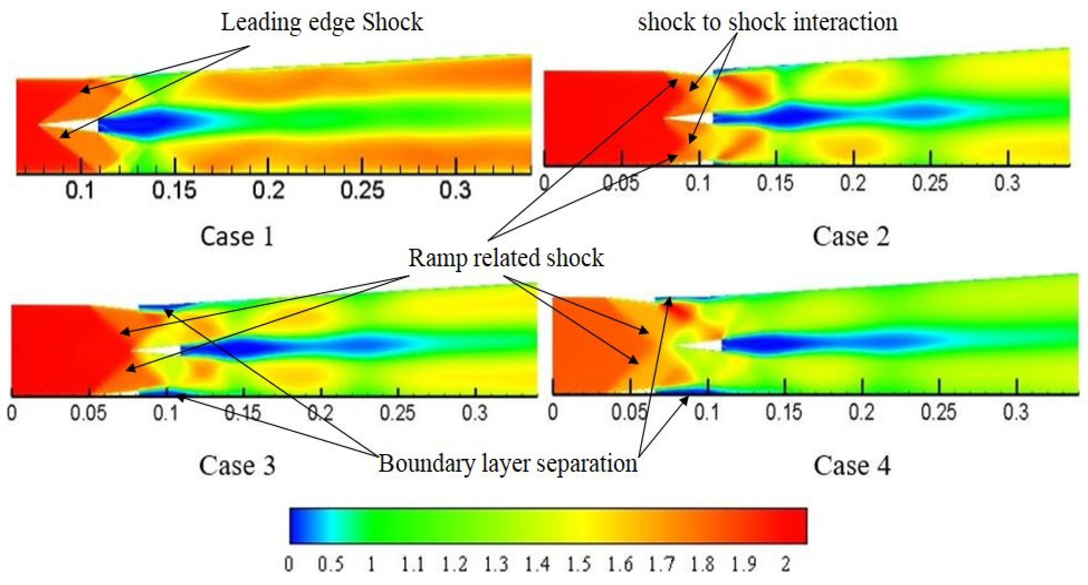
Figure 7 shows the Mach number contour of the reacting flow fields of various cases of the study. For Case 1, due to the shock shear layer interaction, a subsonic region is formed downstream of strut injection where the hydrogen–air mixing and combustion are established. The insertion of ramps, Case 2, in the DLR combustor, generates multiple shocks to shock and shock to shear layer interactions, resulting in the deceleration of flow downstream of the strut injector. As the ramps, Case 3 and Case 4, are moved in the upstream direction of the strut, the strength of the oblique shock increases and decelerates the flow downstream of the strut. Moreover, the flow downstream of the ramp acts as a backward-facing step where a subsonic recirculation region is formed on the top and bottom wall of the combustor.
Figure 8 presents the recirculation regions downstream of strut injection for various ramp axial locations of the combustor and compares them with the DLR scramjet model. It is well known [
1,
56] that the recirculation within a scramjet combustor, either within the cavity or any other mechanism that transports the injectant, enhances air–fuel mixing and increases the residence time of a fuel–air mixture within the combustor. Moreover, it decreases the ignition delay and enhances the flame holding and combustion efficiency. For Case 1, the recirculation region is observed downstream of the strut injector to an axial distance of X = 0.15 m. The size of the recirculation zone decreases downstream of the strut injector, less than X = 0.12 m, by incorporating the wall-mounted ramps, Case 2, in the supersonic flow field. However, a large recirculation region is observed at X = 0.16 m, where the shock wave interacts with the fuel stream that reduces the airflow velocity and enhances the fuel–air stream interaction. Moreover, active vortices are observed downstream of the ramps. For Case 3, the size of the recirculation region decreases immediately downstream of the strut injector, approximately X = 0.115 m from the strut base, and the size of active vortices at the base of the ramps increases. A large recirculation region with more active vortices is observed at the strut base for Case 4. This is because more shock interactions upstream of the strut decelerate the flow to low supersonic velocity.
3.1. Wall Static Pressure
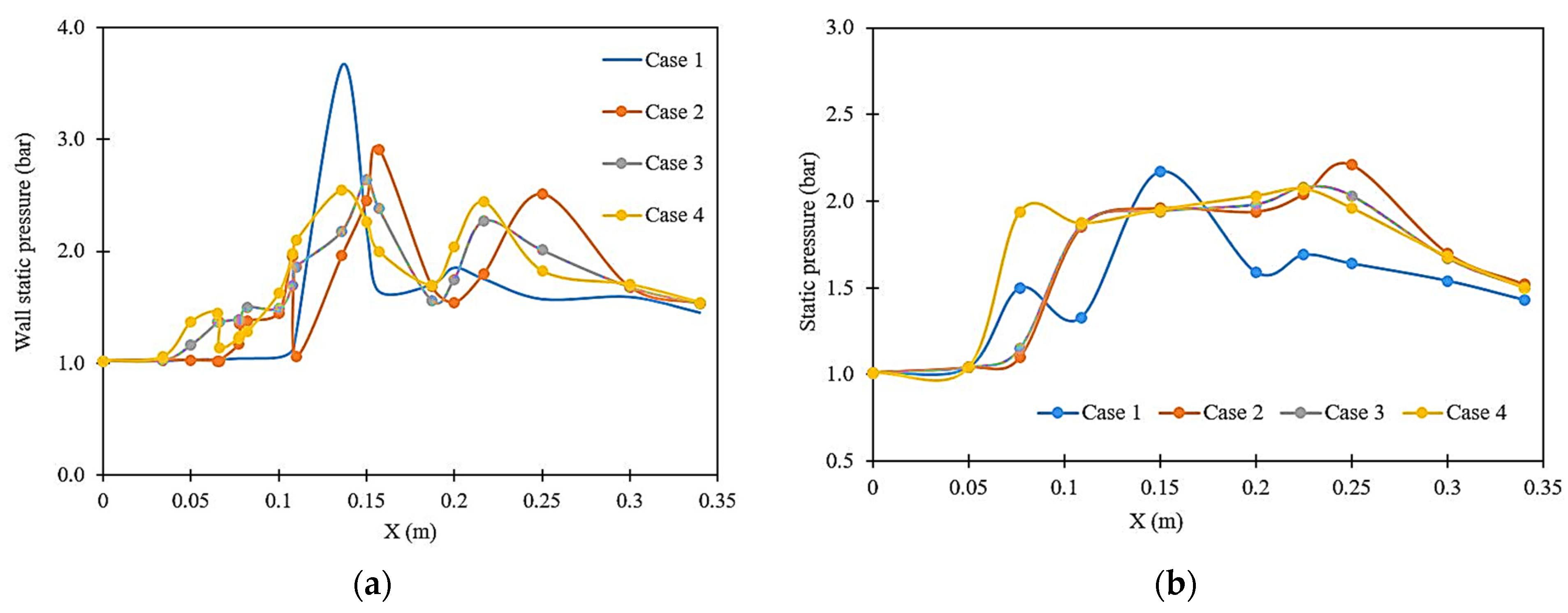
The static pressure distribution at the bottom wall and the centerline of the combustor along the axial direction of the flow are plotted in
Figure 9. From
Figure 9a, the peak pressure is noted at the X ≈ 0.13 m for the DLR scramjet model shock boundary layer interactions where intensive combustion occurs. The constriction of this reaction zone occurs at X ≈ 0.15 m where the pressure reduces drastically, and then a slight increase in pressure occurs at X ≈ 0.2 m where the shock reflections occur at the bottom wall. The static pressure decreases downstream of the location due to the acceleration of the flow to supersonic speed. By placing the ramp parallel to the strut, Case 2, an increase in pressure value is noted at X ≈ 0.157 and 0.25 m, which indicates that shock to boundary layer interactions occurs in these two locations but with less intensity than Case 1. For Case 3 and Case 4, the wall pressure increases ahead of the strut as the ramps are moved towards the inlet of the combustor. This is due to the flow separation formed at the ramps. Moreover, the shock interactions with the boundary layer downstream of the strut are noted with less intensity. From the centerline pressure
Figure 9b, it is observed that the static pressure increases downstream of the strut, which indicates an increase in the subsonic region along the fuel stream flow direction, which may further increase the shear-induced mixing with the supersonic stream.
3.2. Mass Fraction of H2 and H2O
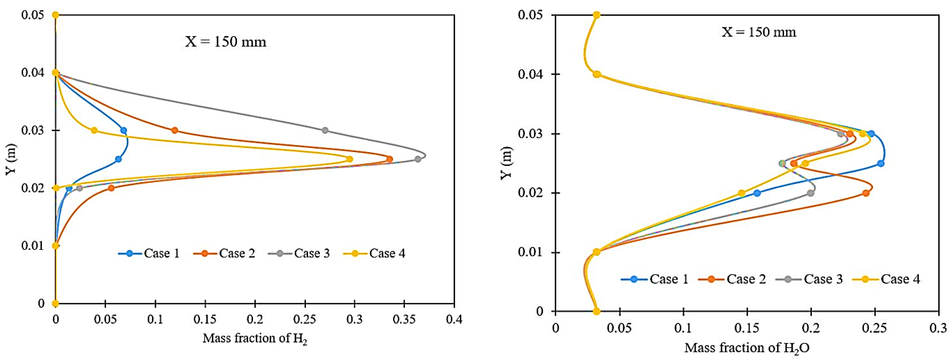
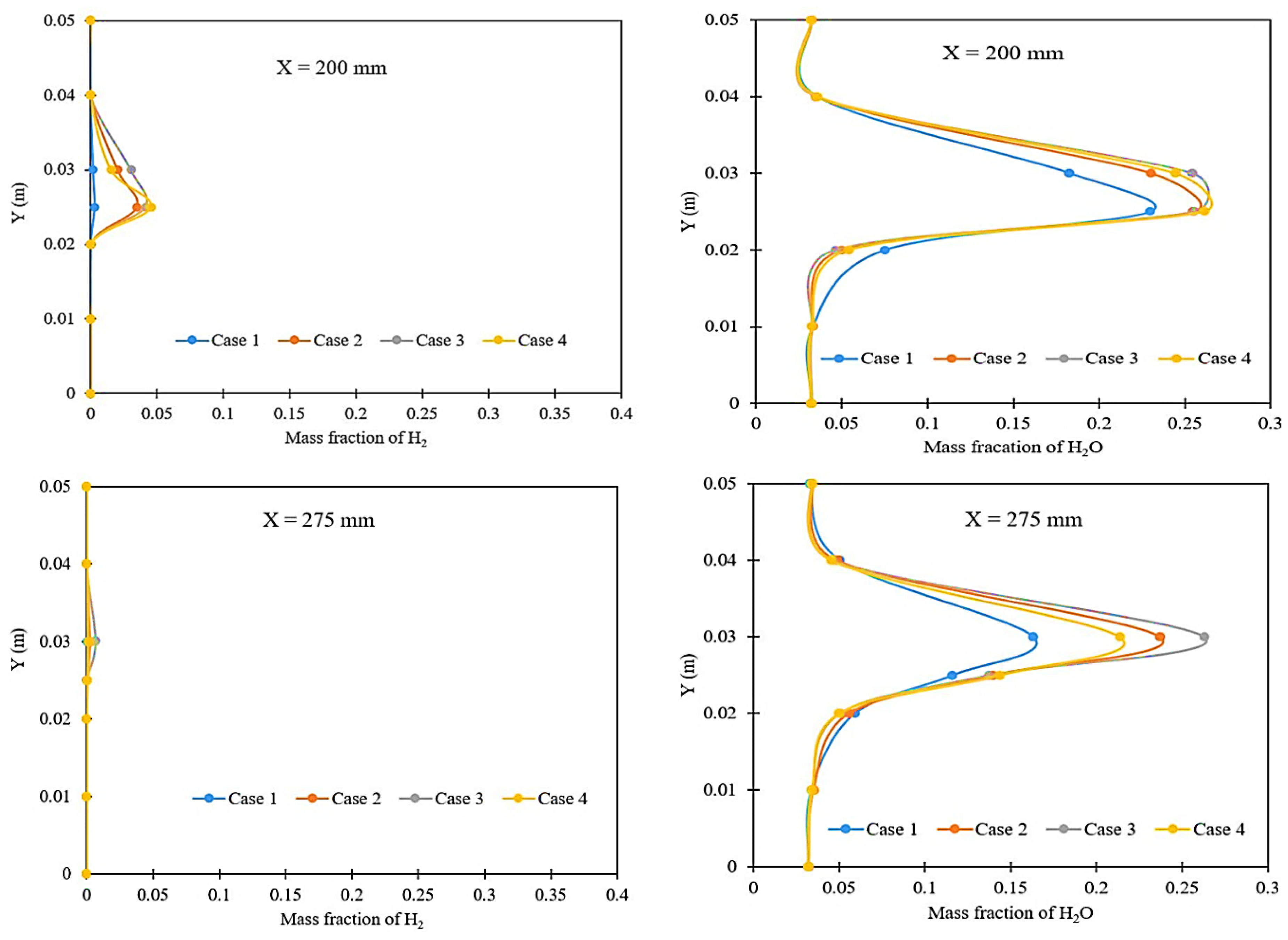
The mixing and combustion of the hydrogen–air in a double ramp-based strut injector is analyzed based on the mass fraction of reactants and products along the combustor.
Figure 10 represents the plots of the mass fraction distribution of H
2 and H
2O at the different axial locations of the combustor. Three stream-wise axial locations considered to analyze the mass fraction of H
2 and H
2O concentration are at X = 150, 200 and 275 mm. The maximum hydrogen mass fraction is observed at the location X = 150 mm, which is nearer to the injector. The hydrogen mass fraction decreases as the axial distance progress in the downstream direction of the flow. In the cases of double ramp scramjet models, the hydrogen mass fraction is higher at X = 150 mm than the DLR scramjet model. This is because the shock to fuel stream interaction is stronger for Case 1, whereas in the double ramp-based scramjet combustor, the shock to shear layer interactions are comparatively weaker, and shock reflections are seen downstream of the strut injector. However, at X = 275 mm, the hydrogen mass fraction is almost null, indicating that the nearly complete combustion is achieved with the double ramps.
From
Figure 10, it is noted that the H
2O mass fraction increases with a decrease in the mass fraction of the hydrogen along the axial direction of the flow. Additionally, the mass fraction distribution of both the reactants and products enhances the combustor wall for the double ramp scramjet combustor compared to Case 1. Furthermore, it is observed that the hydrogen jet penetration into the supersonic airflow is negligible near the walls of the combustor.
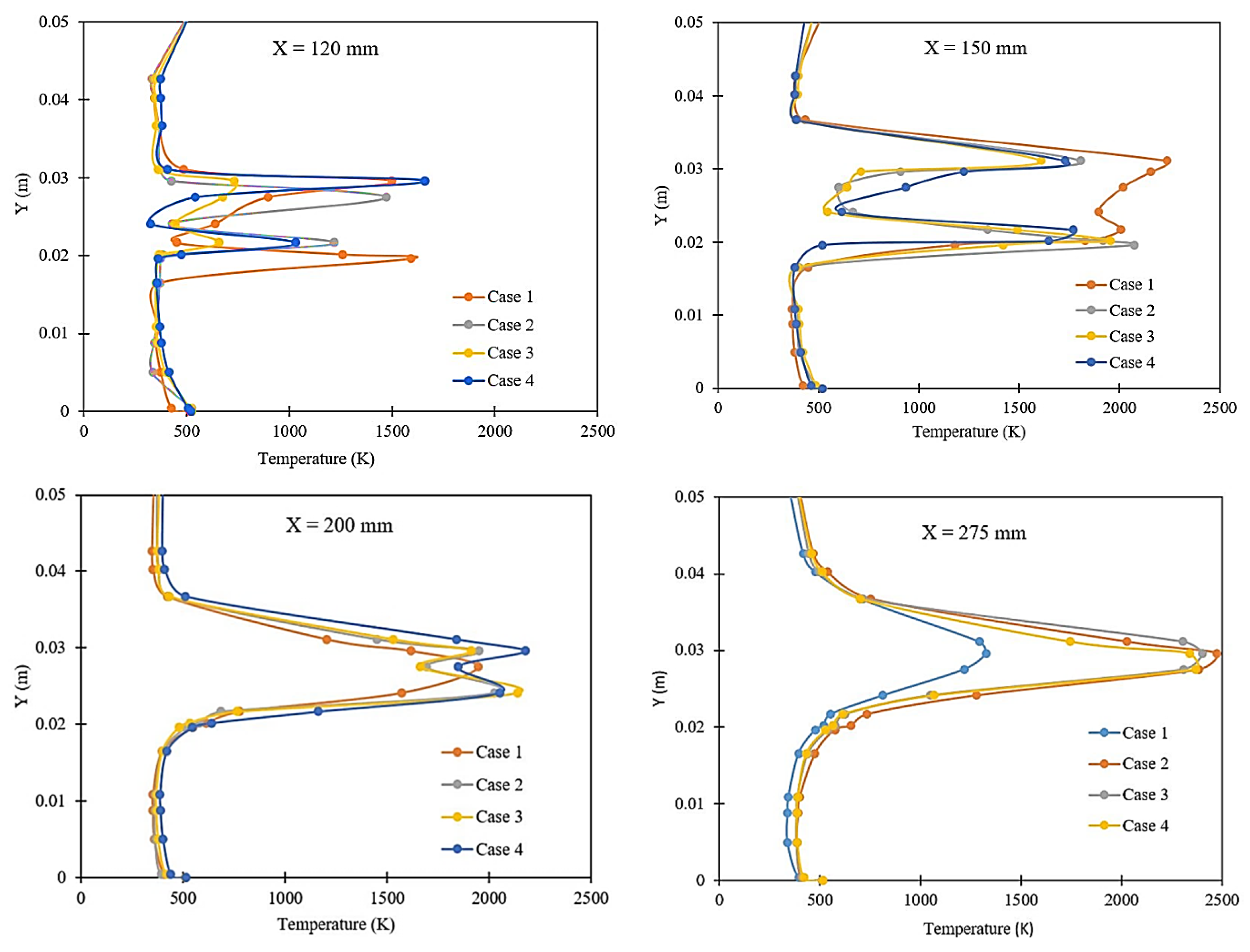
3.3. Temperature
The temperature profile indicates the combustion flame spread in the supersonic flow field of the combustor domain.
Figure 11 shows the temperature distribution plots for the different cases of the scramjet model at four axial locations of the combustor. For all the cases, at X = 120 mm, the temperature profile is almost identical, showing that mixing and combustion of the fuel with air at the injection location are lower compared to the periphery of the streams. This is because the fuel injection velocity is high and the axial length progresses to X = 150 mm; the DLR scramjet model provides the maximum temperature zone at the center of the combustor compared to the ramp combustor model. This is because the strong shock to fuel shear layer interactions create a subsonic region where an intense combustion process happens, whereas for ramp combustor models, the shock to shock interactions decelerate the flow downstream, and the fuel–air stream interaction occurs further downstream of the strut injector. It is observed that the maximum temperature for Case 1 is 2000K. A peak temperature is noted for ramp combustor models, Case 2, Case 3 and Case 4, at an axial distance of 275 mm than for Case 1.
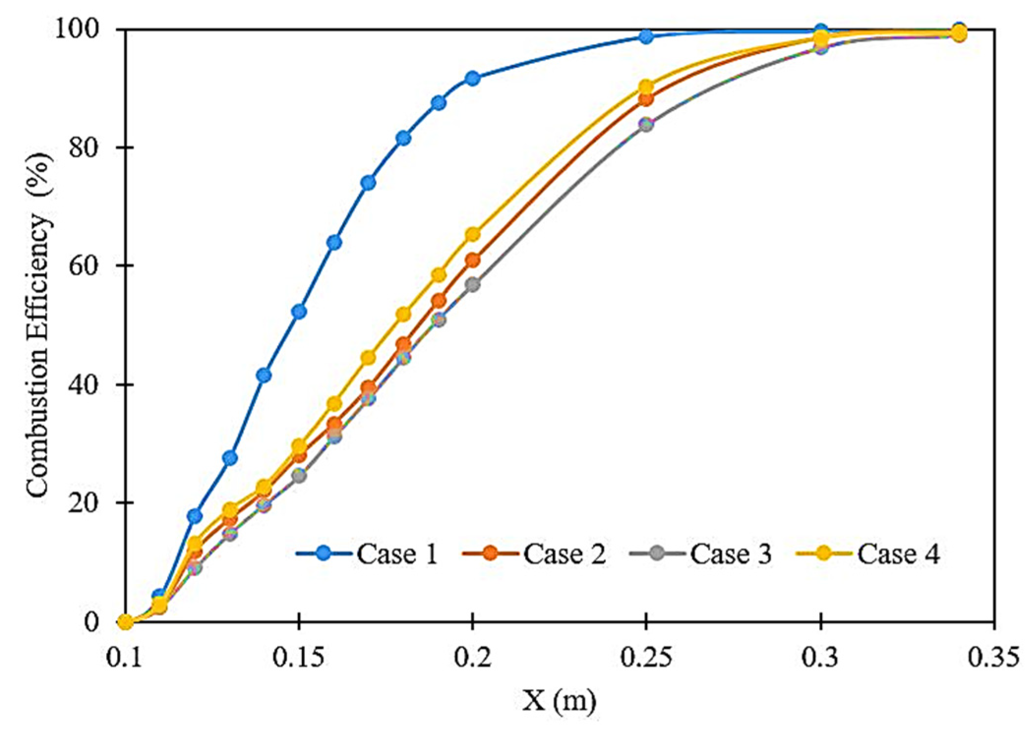
3.4. Combustion Efficiency
In supersonic combustion, the most important parameter is combustion efficiency, which is used to characterize the combustion performance of the combustor [
56]. The combustion efficiency is calculated by the following equation,
where
is the mass flow rate of hydrogen at a given section, and
is then injected hydrogen mass flux. The combustion efficiency for four different cases is shown in
Figure 12. From the plots, almost complete combustion efficiency is achieved at 0.275 m for the DLR scramjet model. However, in the ramp scramjet combustor, Case 2 to Case 4, the complete combustion is achieved at X = 0.32 m from the inlet of the combustor. The shock interactions from the ramps and strut decelerate the flow downstream of the strut, which increases the ignition delay compared to the DLR model.
3.5. Total Pressure Loss
The oblique shock waves generated from the strut and the vortices are because the ramp at the top and bottom wall of the combustor enhance the mixing of air–fuel, which leads to total pressure loss. Pressure loss across the combustor is calculated using the following expression.
Figure 13 shows the total pressure loss for various geometry profiles of the combustor. It is noticed that the total pressure loss increases with the position of ramps downstream of the strut regime. From
Figure 6, it is observed that the intensity of the shock shear layer interactions becomes less for ramp cases, compared to Case 1, and more shocks are observed for ramp cases. As a result, the shock interactions in the supersonic flow field reduce the flow velocity downstream and the total pressure as well. The total pressure loss is maximum for Case 4, approximately 34.45%. However, the total pressure loss for Case 1 is 31.47%. The increase in total pressure loss is due to intense shock reflections and shock impingement on the jet stream that reduce flow velocity in the combustor, which is observed from the Mach number contour.
4. Conclusions
Numerical investigations on the effect of the ramp on the top and bottom wall of a strut-based scramjet combustor are compared with basic DLR strut under reacting flow conditions. A 2D compressible RANS equation with an SST k-ω turbulence model was used for the study. The flow characteristics, such as shock structure, wall pressure distribution, temperature distribution across the combustor, combustion efficiency and total pressure loss, are reported. The qualitative and quantitative computational solutions are compared with the reported experimental data and are noted with an acceptable agreement. The numerical shadowgraph images reveal that more shock to shock, shock to shear layer and shock to boundary layer interactions are noted for the double ramp and strut injector scramjet combustors compared to the DLR scramjet model. In addition, more vortex regions are found in the combustor with ramps. A higher wall static pressure is observed for the DLR scramjet model, whereas, for the ramp cases, upstream flow separation and downstream shock to reflections at two locations with less intensity are found. It is observed that the hydrogen distribution enhances in the spatial direction with more ignition delay for the double ramp combustor. The total pressure loss is enhanced for double ramp combustors due to more shock interactions resulting in deceleration of the flow, which is not seen for the DLR scramjet model. Further studies could be performed on the ramp combustor under varying injection pressures and fuel equivalence ratios.


 ,
, 


