Article

Fuel Cells Based on Natural Polysaccharides for Rail Vehicle Application

1
Łukasiewicz Research Network–Rail Vehicles Institute “TABOR”, ul. Warszawska 181, 61-055 Poznań, Poland
2
Faculty of Chemical Technology, Poznan University of Technology, ul. Berdychowo 4, 60-965 Poznań, Poland
*
Author to whom correspondence should be addressed.
Energies 2021, 14(4), 1144; https://doi.org/10.3390/en14041144
Submission received: 12 January 2021 / Revised: 9 February 2021 / Accepted: 17 February 2021 / Published: 21 February 2021
(This article belongs to the Special Issue Biomass Conversion Technologies)

Abstract

:
This manuscript shows the use of natural polysaccharides such as starch and cellulose as a carbon source for fuel cells. To achieve this, two innovative methods of obtaining hydrogen have been shown: by adsorption and by enzyme. The carbonization path of the material results in excellent sorption properties and allows gas with high efficiency to be obtained. The enzymatic method for the degradation of the compound is more expensive because specific enzymes (such as laccase, tyrosinase) must be used, but it allows greater control of the properties of the obtained material. A scientific novelty is the use of natural raw materials, the use of which increases the biodegradability of the electrochemical system and also reduces the cost of raw materials and increases the range of their acquisition. Energy should be generated where it is used. Another goal is decentralization, and thanks to the proposed solutions, hydrogen cells represent an innovative alternative to today’s energy giants—also for independent power supply to households. The proposed harvesting paths are intended to drive rail vehicles in order to reduce emissions and secondary pollution of the environment. The goals of both methods were easy recycling, high efficiency, increased environmental friendliness, low cost and a short hydrogen production path.

1. Introduction

An important step towards reducing the burden of rail transport is putting into service hybrid locomotives, which are perfect for shunting and running trains on non-electrified lines [1]. The principle of operation is similar to that of buses and passenger cars with hybrid drive: a combustion engine is used alternately or only electric motors powered by batteries are used. The batteries are charged during combustion engine operation and during braking, by energy recuperation.
Designers of hybrid locomotives have more freedom compared to their colleagues in the field of cars: traction motors are electric, so there is no need to experiment with changing them. There is also more freedom in the selection of batteries in terms of size and weight, although, on the other hand, locomotives have a much higher demand for energy, which necessitates the use of batteries with a larger capacity and greater permissible current.
Locomotives with hybrid drive are offered by many manufacturers. In Europe, they are offered by Alstom, Siemens (which sells them on the American market, among others); Newag is also working on a hybrid train project. In the US, General Electric has been manufacturing hybrid freight locomotives since 2007. Asian manufacturers are also present on the market—for example, Toshiba [2].
Hybrid locomotives have one further use: they help to shape the owner’s image, emphasizing their care for the natural environment at every stage of production. This is the role of the hybrid diesel locomotive, produced with plug-in technology by Alstom for the Audi plant in Ingolstadt. The technological transport in the plant is organized in such a way that the components are delivered to individual production halls by rail transport. Finished vehicles also leave Ingolstadt by rail.
Each locomotive at the Audi plant performs an average of 75 maneuvers per day, and the annual working time is around 3800 h. The use of one hybrid locomotive reduces annual carbon dioxide emissions by almost 60 tons. The specificity of plug-in technology is that the traction batteries can be recharged in two ways: while driving—from a generator driven by an internal combustion engine—and during breaks in work—from an external source. Actual emission reduction can only be discussed when the electricity comes from a clean source.
There are many indications that hybrid electric locomotives will soon be considered a standard where the construction of the electrical network is impossible or unprofitable. Using only electric locomotives would be more ecological, drawing energy from batteries charged from an external source. However, it seems that in the near future, batteries that would allow train driving of such locomotives are unlikely to be produced. They will probably find their niche as shunting locomotives in factory technological transport, in which the intervals between maneuvers are long enough to enable effective battery charging.
Electric locomotives, by nature, do not emit pollution, but this does not mean that they have no impact on the environment. It is necessary to look at electric traction from a broader perspective. Electric locomotives do not emit pollution locally, but if the energy supplying them is generated in outdated, high-emission coal power plants, the idea of clean transport is questionable.
To improve this situation, two actions can be taken: reduce energy demand and buy it from producers using clean, renewable sources. For example, Dutch railways are moving in this direction, which, until 2018, are to be powered exclusively with energy produced from renewable sources: wind farms.
The development of electric locomotive drives contributes to reducing the consumption of traction energy and recuperation during braking. There are also hybrid constructions, but these have a slightly different purpose than in the case of diesel locomotives. Classic electric locomotives can only reach where the overhead catenary has been built. This means that, in many cases, shunting diesel locomotives must be brought to the area belonging to the cargo recipient. Equipping the electric locomotive with a battery of traction batteries enables the passage of non-electrified sections with their own forces, which significantly reduces the time of transport and helps reduce environmental impact.
The impulse for electrification of long-distance traction with high rated voltage was drives with acceptable losses in lines in such circumstances. An asynchronous machine, and, in particular, a reliable induction motor, was, and is today, the workhorse of traction. Different strategies are used to feed the traction motors for the same reasons as originally, i.e., to minimize losses. Low-emission transport is most often associated with rail transport. This type of vehicle has many advantages—it is ecological, relatively quiet and efficient (it can take many passengers at the same time). In addition, the European Union is increasingly paying attention to the need to rebuild rail transport, which is of fundamental importance for the development of many localities, increasing their economic and tourist potential, and contributes to the improvement of the environment. This article discusses selected solutions for modern rail vehicles (locomotives), which contribute to improving the fulfillment of transport needs. These vehicles are often already equipped with technologically advanced exhaust gas cleaning systems, with the use of liquid and gaseous biofuels and the use of alternative propulsion sources. They exert a less negative impact on the natural environment. An innovative solution was presented in the form of a rail vehicle powered by fuel cells, using hydrogen for the production of electricity, which has been gaining popularity in recent years. Another modern solution among railway vehicles is those with hybrid drive systems, the hybrid drive unit of which consists of a piston internal combustion engine, an electric motor with a drive train and a set of highly efficient energy storage devices.
Fuel cell technology is one of the most promising future energy generation technologies. It consists of the direct conversion of the energy of chemical bonds in the fuel into electricity through chemical reactions, mainly oxidation. It is a naturally pure technology. The level of harmful emissions related to the operation of a fuel cell is negligible in comparison with, for example, combustion technology, because the main emission component is water vapor. The efficiency of fuel cells largely exceeds other types of energy conversion—depending on the type of fuel, the electrical efficiency of a typical cell is in the range of 40–60%, and the total efficiency can reach 80–90%. There are many types of fuel cells for both mobile and stationary applications. The Institute of Energy is developing the technology of Solid Oxide Fuel Cells (SOFC). These are high-temperature fuel cells (operating in the temperature range of 600–1000 °C) intended for stationary applications. The advantage of SOFCs is the possibility of using not only pure hydrogen as fuel, but also other fuels such as natural gas, methanol, synthesis gas (obtained in the process of biomass or coal gasification), LPG, biogas and others. The main goal of research related to fuel cell technology is to reduce costs, improve durability and transfer the technology from the laboratory to industrial scale. Research work in this area requires advanced knowledge in many fields and an interdisciplinary approach.
In order to minimize the negative impact of the internal combustion fleet on the environment, works on the use of eco-friendly hydrogen fuel have been undertaken. The hydrogen used is the lightest and most widespread element in the universe. It is predicted to make up 92.7% of the atoms in the universe, followed by helium with 7.2%, and the rest of the elements only 0.1%. In the free form in the Earth’s crust, there is only a trace amount of hydrogen (0.15%). In the Earth’s atmosphere, it is even less than 0.1 ppm. Almost unlimited deposits of hydrogen will be bound to other elements, including water, hydrocarbons, organic substances, living organisms and inorganic compounds. There are many possibilities of obtaining hydrogen from this type of compound, but they are affected by a more or less favorable energy balance. In the energy sense, hydrogen is perceived as a way of transporting energy, but its processing in thermal machines has resulted in its inclusion in the family of fuels on par with natural gas, gasoline or diesel fuel. Hydrogen has the highest thermal conductivity of all elements, amounting to 0.1745 W/m K, and specific heat of 14.195 kJ/kg K in 273 K.
Compared to conventional fuels, hydrogen has the highest energy value in relation to the mass unit, equal to 121 MJ kg−1 (for example, coal 25 MJ/kg, gasoline 47 MJ/kg). In relation to the volume unit, due to the low gaseous density (273 K, 1013 hPa) amounting to 0.089 kg m−3, its energy value is no longer impressive and amounts to 10.7 MJ/m3. The density of hydrogen can be increased by increasing its pressure. Combusting hydrogen with oxygen produces water and energy. The advantage of this process is the formation of environmentally harmless compounds, which is not encountered in the case of hydrocarbon fuels. The energy obtained in the oxidation process after measurement allows the determination of the upper and lower combustion heat source. The difference between these values is the heat of evaporation, which is part of the energy needed to convert the fuel from a liquid to a gas state and to convert a solid to a liquid. The solutions presented in the article are not about its oxidation in the working space of a piston engine (which is the case with some road vehicles), but about its use for the production of electricity using high-performance fuel cells. Fuel cells using hydrogen to produce electricity are gaining popularity in the automotive industry among individual car manufacturers. The automotive industry is increasingly leaning towards alternative drive systems.
Energy recuperation during braking can be used in electric locomotives in several ways. First of all, if the method of measuring traction energy and the contract with its supplier allow it, it can be possible to return the energy recovered during braking to the traction network and thus reduce the traction energy bill. Secondly, it can be used to charge traction batteries and used when the demand is particularly high—for example, when starting and accelerating the depot—which allows reduced energy consumption from the network.
Modern energy recuperation systems have some limitations resulting from the design of railway braking systems. Only the portion of energy that falls on the locomotive is recovered. In fact, it brakes the entire train, but the braking energy of the wagons is dissipated and lost permanently.

2. Experimental Section

2.1. Materials

Starch (Sigma Aldrich, St. Louis, MO, USA), or homopolysaccharide, consisting of glucose units, is a valuable source of both hydrogen and carbon. Its main structural units are amylose and amylopectin. It is located in, among others, maize, potatoes, rice, wheat and peas, i.e., products that are characterized by a low acquisition price and are popular in nature. Starch in its polychains has large amounts of hydrogen, which can be extracted from the structure using appropriate methods. Amylopectin, which is a source of chain branching, influences its higher packing density, as well as the porosity of the structure and the well-developed specific surface after thermal treatment. Starch is a semi-crystalline compound, with a predominance of amorphous areas, which allow the significantly better transfer of charges inside the structure. Biodegradability of starch is related to the high content of water and reactive hydroxide groups on its surface, reaching even thousands of mg OH/1 g of starch, which favors endothermic biodegradation reactions, causing weight drops to 80% during thermogravimetric tests, and allows it to be used as a green material with many possibilities of modification due to the content, incl. hydroxyl groups, methyl, carbonyl and ether groups.
Cellulose (Sigma Aldrich) is an unbranched polysaccharide biopolymer containing 3000–14,000 D-glucose particles linked by ß-1,4 glycosidic bonds. The powdered cellulose itself is a valuable adsorbent, e.g., in chromatography and as a filler or for thermal insulation due to its extremely high storage capacity (energy insulation). It is widely used in the pharmaceutical industry as a filling and disintegrating excipient, and it can be found primarily in trees. The large number of forests allows the use of cellulose and lignin wood without the use of separating processes, as their naturally occurring mixture and after chemical treatment. Cellulose contains starch that occurs naturally in bread, rice and potatoes. One of its components is glucose and it is possible to use this when seeking energy to produce hydrogen. From 100 billion tons of cellulose, as much as 4.5 billion tons are obtained, i.e., twice as much as the global annual production of cereals. The properties of cellulose depend, among other aspects, on the origin of the wood and how it is processed, the environment and growing conditions. Similarly to starch, it is a biodegradable material and a valuable source of carbon and hydrogen, and it is rich in hydroxyl groups, which increases its workability.

2.2. Design Innovation

The use of two polysaccharides commonly found in nature and waste is the basis of the implementation of the concepts of Green Chemistry on a large scale. The idea makes it possible to design hydrogen-powered cells obtained by enzymatic means and adsorption processes, which will then enable the powering of vehicles by designing a fuel cell. A special innovation will be their use in city buses and passenger cars, as well as agricultural tractors, due to the appropriate selection of process parameters and high extraction efficiency. This will lower the charging cycles of the cell. The cell will also work freely at low temperatures by increasing the range of glass transition temperatures, so that it will not be damaged due to unfavorable weather conditions. Additionally, it will be an extremely safe cell, because, for example, starch is a non-Newtonian fluid, so in the event of a collision, it prevents the electrolyte from entering the electrodes, thus preventing the cells from exploding and reducing the accident rate of vehicles.
Our aim was to develop an alternative energy source: a hydrogen supply system (adsorption production), a fuel cell powered by the produced hydrogen and an application for the use of hydrogen, e.g., including a hydrogen energy storage system and fueling the vehicle. Thus far, laboratory-scale research has been carried out using a tube furnace to carbonize starch, cellulosic and the optimization of the process has been carried out on a laboratory scale. The processes of adsorption on carbonaceous material and the desorption of hydrogen gas, which is the main product of the process, were carried out with the use of basic laboratory equipment.

3. Results

Fuel cells are energy convertors that convert chemical energy into electrical energy at high thermodynamic efficiencies [3].

3.1. Technical Requirements

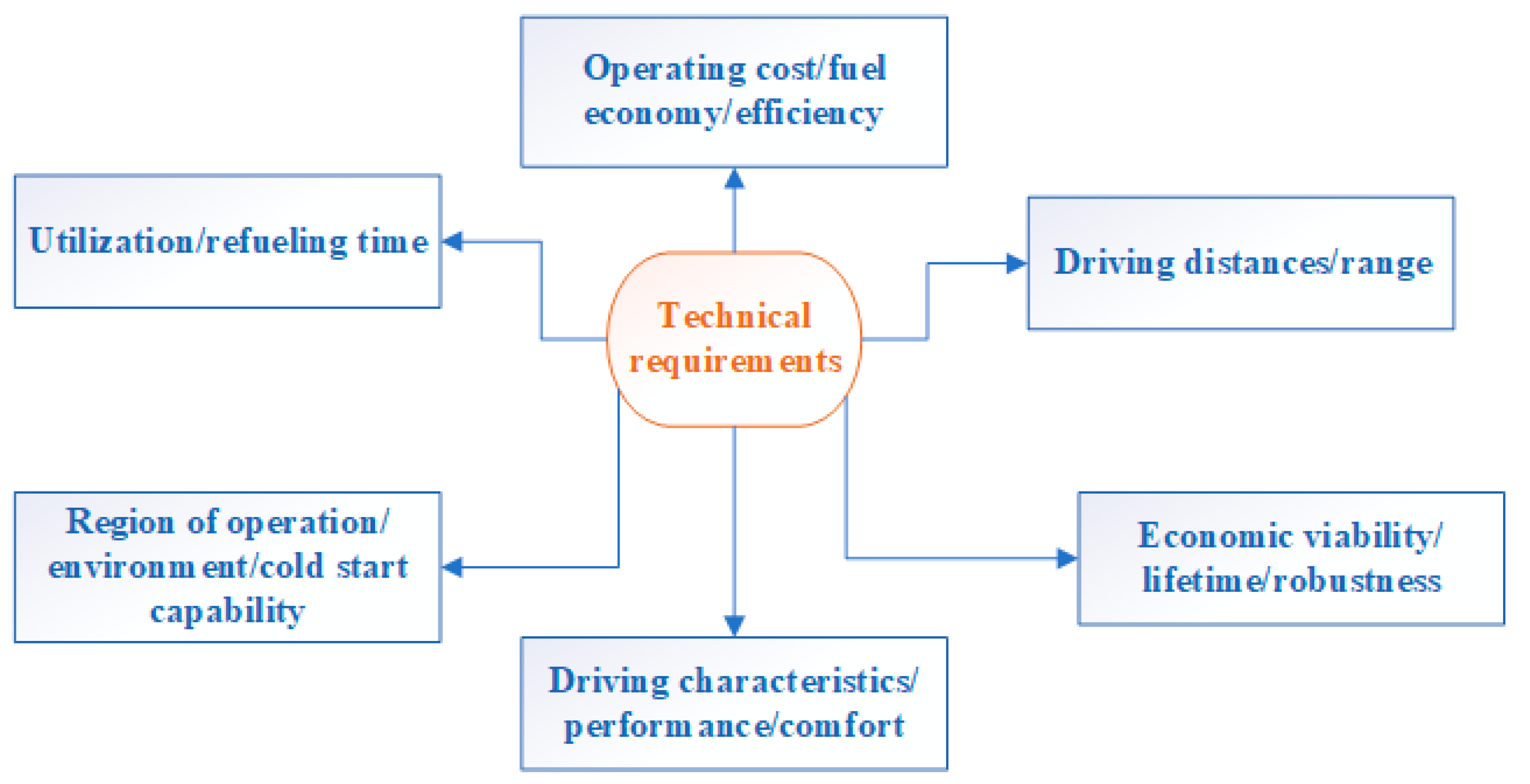
The fuel cell vehicle has to meet specific requirements. Aspects that need to be taken into consideration include environmental conditions, economics and vehicle performance characteristics. Some of the most important technical requirements are presented in Figure 1.
The use of two commonly occurring polysaccharides is the basis of the implementation of the concepts of Green Chemistry on a large scale. This idea enables the design of hydrogen-powered cells obtained by enzymatic means and adsorption processes, which will then enable the powering of vehicles by designing the fuel cell.
Electromobility is gaining momentum. This is an important part of reducing CO2 emissions from road traffic. However, how economical is it to operate large trucks with a 40-ton load over long distances using only electricity from batteries? Given the weight of batteries, long charging times and the limited range of today’s technology, electric propulsion systems are not the best choice for trucks. Despite this, even 40-ton trucks will be able to cover more than 1000 km in fully electric mode in the near future. The key to this is the fuel cell driveline. Powered by hydrogen produced using renewable energy, this type of drive train enables climate-neutral transport of goods. Once established in trucks, fuel cell powertrains will increasingly appear in passenger cars—rightly becoming an integral part of the future powertrain portfolio.

3.2. Locomotives Powered by Hydrogen Fuel Cells

Currently, there is strong interest in fuel-cell-powered locomotives for sustainable transportation. In Table 1, a review of the developments during the years 2002–2016 is presented.
Rail transport plays a very important role in providing land transport services. The technological process that is used for rail transport has a significant impact on the rail economy. Consequently, it is also important for the national economy. The condition for the proper development of rail transport is the successive replacement of steam traction by electric traction. The evolution of electric traction depends on the increase in the rate of electrification and modernization of traction. Railway electrification is one of the basic elements of the modernization of railway transport, and it determines the capacity and costs of transportation. Its introduction allows a significant reduction in the operating costs of rail transport and energy and fuel savings [14].
The dual-mode vehicle can use both diesel and electric propulsion. The new locomotives are powered by electricity on electrified sections of the line, saving fuel and reducing maintenance costs. The locomotive can be switched to diesel mode on non-electrified sections. Thanks to the dual-mode concept, operators can increase their environmental contribution throughout the life cycle of the locomotive.
It is also possible that diesel trains could run on electrified components along partially electrified lines. Vectron Dual Mode combines the best features of two areas: it is equipped with both a powerful diesel engine and an electric drive. Where there is an overhead catenary, the locomotive runs quietly without emissions, saving fuel and maintenance costs. The Vectron Dual Mode is a sustainable, environmentally friendly and cost-effective alternative to conventional locomotives, as highlighted by Sabrina Soussan, Siemens Mobility. Germany’s rail network is currently around 60 percent electrified, and new locomotives from Siemens Mobility can also operate between electrified sections, eliminating the need to change locomotives. This allows agglomerations and metropolises, where rail networks are often electrified, to reduce emissions.
Such trains include regional passenger trains, shunting or mainline locomotives. According to numerous trade magazines, for some prototypes of FCH (fuel cell hydrogen trains—hydrail) passenger trains, in recent years, their operating principle was not only developed but also tested. The interest in this technology demonstrated by many public transport authorities (PTAs), both in the EU and abroad, has led to procurement in Austria and Germany for small vehicle doughs to be put into service between 2021 and 2023. The goal is to use fuel and hydrogen in the railway environment. Current special technology allows for a zero-emission and cost-competitive solution to replace diesel trains.
The EU’s goal is a decarbonization method for the production of hydrogen and 33% of green hydrogen in the energy mix in 2050, integrating the EU energy system into a more circular energy system, where energy is not wasted and where energy efficiency is paramount. An important element is also the decline in the prices of RES (renewable energy sources) installations, which will increase their share in the energy mix. Another important aspect is also the promotion of renewable and low-emission fuels, including hydrogen, where electrification and decarbonization are difficult, e.g., in heavy transport and industry. The key sectors of the Polish hydrogen strategy are: transport (urban, rail, truck), energy storage (using the surplus from renewable energy peaks to produce hydrogen), energy-intensive industry (replacing coal/natural gas with hydrogen) and heating (hydrogen mixed with natural gas, from electrolysis). Today, attention is also drawn to the European Common Interest Projects (IPCEI), which are one of the EU’s key instruments to strengthen the potential of European industry in the context of global economic competition. The IPCEI procedure allows Member States to subsidize international projects with high development potential whose value chain is organized in the EU. Within the framework of IPCEI, the entire value chain is designed, i.e., hydrogen production, transport, storage, hydrogen cells for vehicles, industrial use [15,16,17,18,19,20].
Examples of challenges in the areas of climate, energy and mobility include strengthening the European value chain for the near-zero carbon footprint of hydrogen and fuel cells, which offers a major decarbonization pathway for energy, transport and industry. On many aspects, we should also mention a joint venture for fuel cells and hydrogen technologies that supports research, technological development and demonstration activities aimed at accelerating the market introduction of hydrogen technologies, using their potential as an instrument to achieve carbon clean energy [21,22,23,24,25,26,27].
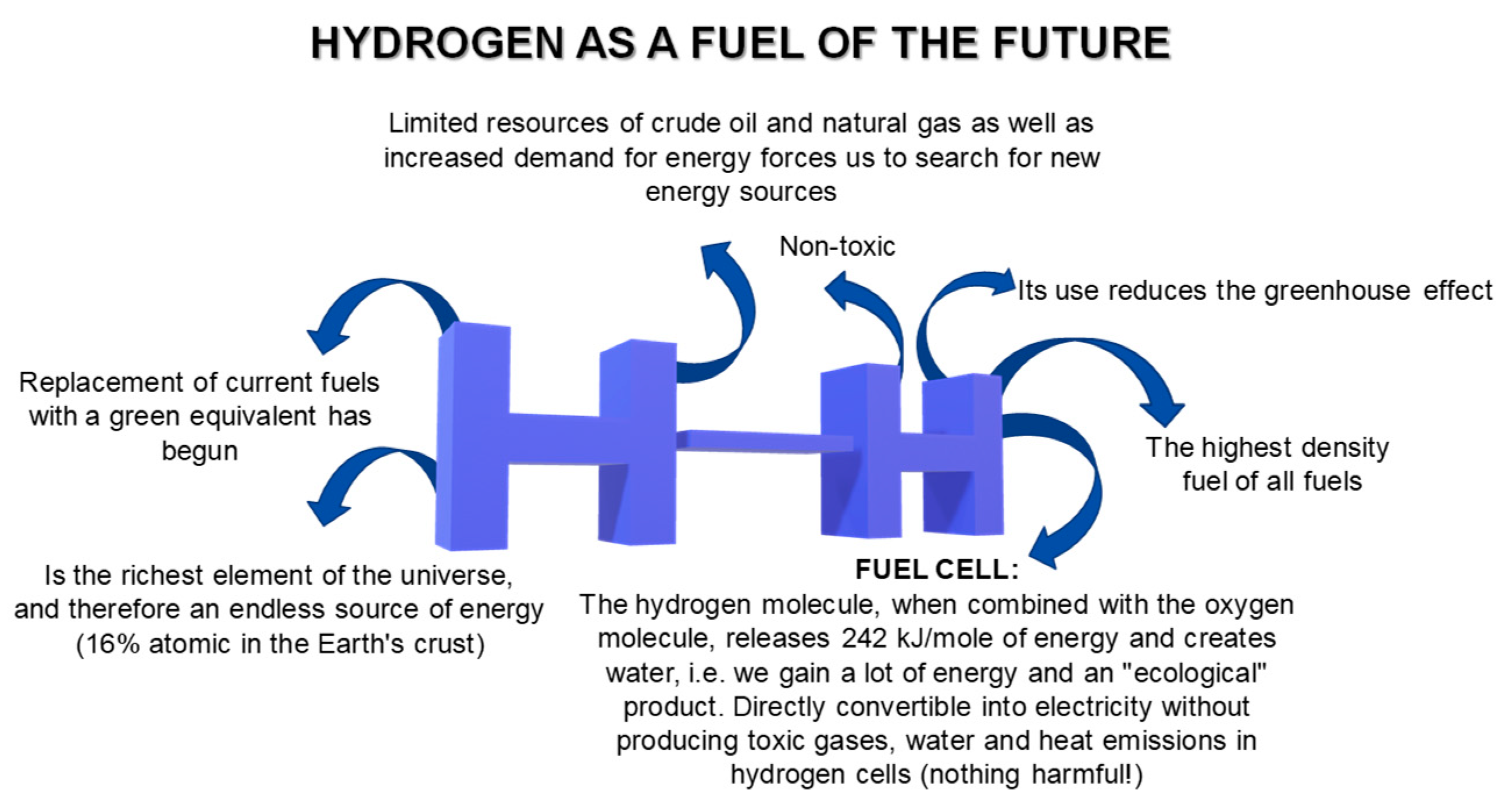
An alternative to many environmental problems is hydrogen technology (Figure 2).
The use of waste (low-cost materials) and naturally occurring raw materials can help to implement the concepts of “Green Chemistry”. The obtained hydrogen may be directly utilized in both hydrogen cell systems and internal combustion engines due to the lack of further conversions. The ability to control the microstructure and morphology allows us to obtain a material with specific properties.
Hydrogen in the industry is already broadly used and the resulting technological achievements are becoming more and more interesting (Table 2).
In addition to the use of hydrogen in the food, chemical and metallurgical industries, it is widely used to produce fuel. In relation to its mass, it has a very low heat of combustion (141.9 MJ/kg) and a huge calorific value of 120 MJ/kg. For the above-mentioned reasons, this element has become the basic component of rocket engine exhaust mixtures, and today, it is beginning to dominate the automotive market. The term “hydrogen economy” has become widely used, which carries information about the positive ecological and economic aspects of using this element as an energy source. Due to the development of civilization, the need to supply energy is constantly increasing. Despite the high hydrogen content in the universe, natural deposits do not exist. Scientists are currently seeking the most efficient way to obtain this highly energetic element, which will meet, above all, the economic requirements, such as low price, simple construction of the necessary devices and high efficiency of the synthesis process.
Hydrogen is one of the most efficient fuels, and its combustion produces only water vapor, which has a positive effect on the Earth’s atmosphere. By using this type of energy source, it is possible to reduce greenhouse gas emissions and the amount of acid rainfall. However, ecological problems still exist during the hydrogen production process itself. The solution is biohydrogen. The prefix “bio” comes from the biological methods of producing this gas. However, an amendment should be made to the strict classification of methods. This high-energy gas is also generated in biomass gasification and biogas conversion processes, which are based on chemical processes. Microorganisms take part in bioprocesses, so the two above-mentioned chemical methods can be included in the biological methods of hydrogen synthesis due to the bacterial activity in the inevitable stages of creating the substrates for ecological fuel.
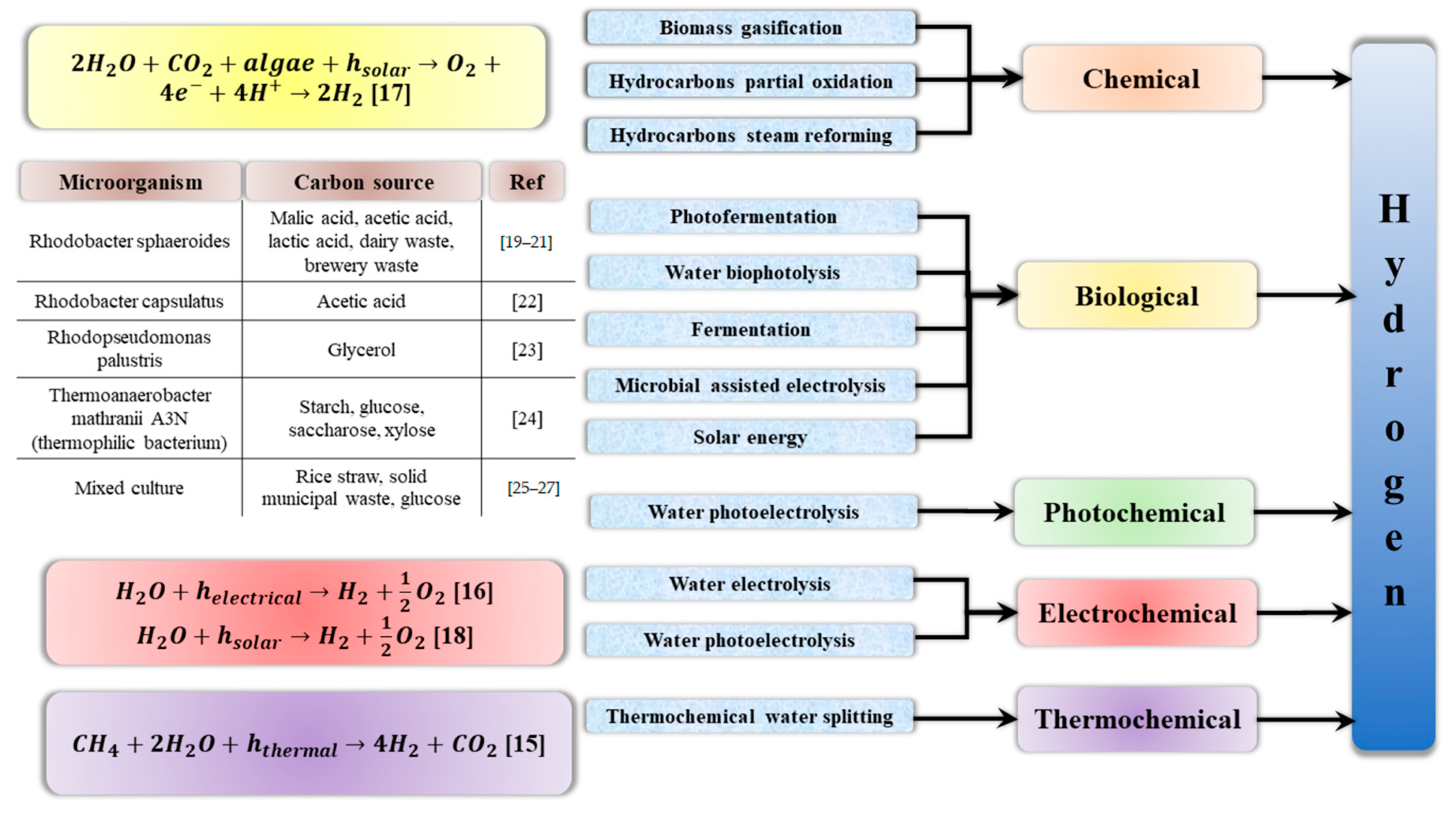
A diagram of the hydrogen production methods is shown in Figure 3.
Although industrial hydrogen can be obtained from water, hydrocarbons and even biomass, currently, as much as 48% of its production is based on methane-reforming using steam, 30% comes from refining crude oil, 18% is released during coal transformations, e.g., in the Haber–Bosch method, and only 4% is the product of water electrolysis [29,30,31,32,33]. Its importance as an energy source grows year by year. The most popular methods of obtaining hydrogen are, unfortunately, still based mainly on exhaustible deposits, such as crude oil. Additionally, fossil fuels are causing global warming to increase by emitting greenhouse gases.
In this respect, biotechnology holds promise, offering both economic and ecological solutions. The production of hydrogen by microorganisms, known as the biosynthesis process, could represent a turning-point in the field of automotive and environmental protection.
Hydrogen synthesis by biodegradation and biotransformation methods usually involves the use of anaerobic bacteria, photosynthetic bacteria, etc., to convert organic material into gas. If this organic degradation of wastewater or other biomaterials can be carried out for energy generation, we achieve double success. The entire process is fully in line with the principles of environmental protection and recycling and can additionally be economically efficient [34]. H2 biosynthesis occurs in various types of biochemical changes; in this respect, renewable energy sources are important. Renewable sources are never-ending and carry many more benefits than losses. For these reasons, biotechnologists are currently focusing on increasing the efficiency of biohydrogen synthesis. Gasification of biomass entails the necessity of separating hydrogen from other products formed in the reaction, the use of catalysts and high pressure or temperature. In the process of water electrolysis, high-purity hydrogen is produced, but this method is quite energy-intensive and therefore very expensive and unprofitable [35]. The use of bacteria to synthesize hydrogen can solve ecological and economic problems, allowing the cheap and fast production of high-purity H2. The conditions that are necessary for the synthesis of this gas by microorganisms are not too high. The optimal room temperature is usually the room temperature and the natural atmospheric pressure, as well as water conditions. The methods of biohydrogen synthesis known so far include: direct photolysis of water with the use of cyanobacteria or algae, decomposition of organic compounds using sulfur-free purple bacteria and fermentation or bioelectrochemical processes, such as bioelectrolysis [33]. Hybrid combinations of the above-mentioned methods are also used. The greatest economic predisposition is shown by biological methods such as biophotolysis or dark fermentation, as well as the use of coupled dark and photofermentation [36].
Ecological methods of producing energy and processing organic matter are becoming more and more important in industry. One of the more interesting methods of obtaining biohydrogen as an alternative energy source is the fermentations described in the previous chapters: light and dark, especially compressed together. Another efficient way to synthesize this high-energy gas is biomass processing. Biomass is a general term that defines the organic material formed during the photosynthesis of green plants, including algae, trees and crops [37]. The use of biomass for the production of hydrogen is highly profitable due to the use of already existing organic matter as a raw material. An important aspect is also the fact that waste is utilized in biomass conversion processes, during which energy is produced. Agricultural crops (sugar beet and oilseed crops) are used as sources of biomass, ligno-cellulosic waste such as wood and wood waste, aquatic plants such as algae and aquatic weeds, industrial or municipal waste and animal waste [38]. It is worth noting that many types of agri-food waste contain starch or cellulose. The complex nature of these carbohydrates can adversely affect their biodegradability. Starch is hydrolyzed to glucose and maltose by acidic or enzymatic hydrolysis, and these carbohydrates are further converted into organic acids and then into hydrogen gas. Agricultural waste containing cellulose requires more extensive pretreatment. It should be ground and, prior to fermentation, delignified by mechanical or chemical means [39].
Graphene itself is not magnetic, but in combination with hydrogen, it represents an additional source of magnetic energy.
Magnetic moments are formed during hydrogenation, when atoms attach to the carbon in the honeycomb carbon layers. Honeycombs are subnetted: the moments align ferromagnetically (blue arrows) when two hydrogen atoms are on the same subnetwork and antiferromagnetically when they are on the opposite lattice (orange arrow). It is the hydrogen atoms that induce magnetism in graphene, which is applicable to the production of universal magnetic ordering within a one-dimensional material. Graphene itself is not magnetic, but in combination with hydrogen, represents an additional source of magnetic energy. It is possible to manipulate the movement of hydrogen by activating and deactivating the magnetic field. When we have a variable magnetic field (movement on a micro scale), a vortex electric field and a reverse one (Maxwell’s theses) are always created around the field, which becomes a source of electricity. Each movement of electrons in a conductor is accompanied by an alternating magnetic field. These fields interpenetrate and move in space—these are electromagnetic waves that travel at the speed of light. Since the arrangement of these hydrogens can be manipulated, the magnetic field can be activated further; that is, the efficiency of the adsorption and desorption process on the same halfnets can be increased if an adsorption and desorption process occurs instead of the absorption process.
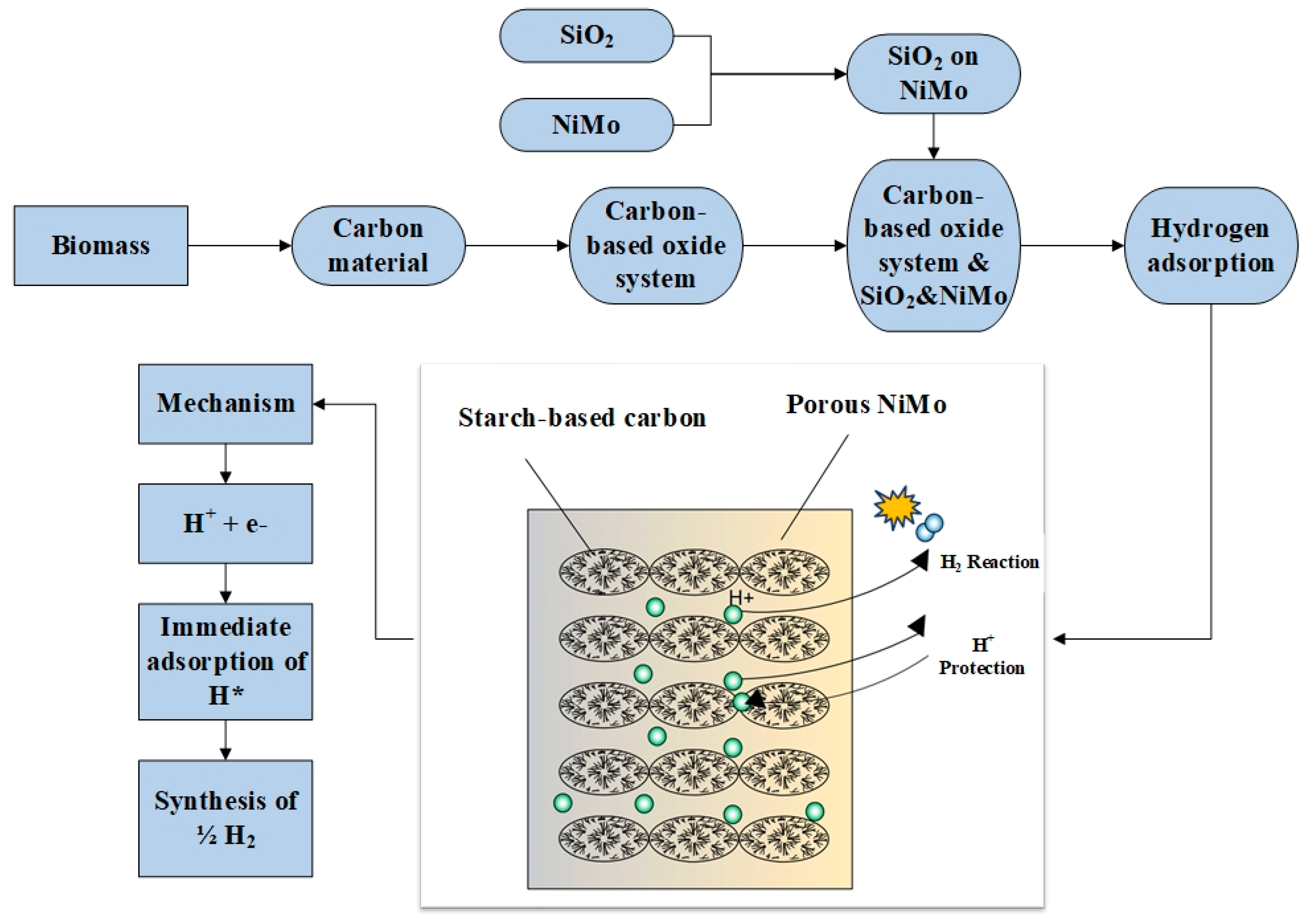
The planned process will be conducted so that adsorption and desorption do not require high temperatures and are as close to room temperature as possible. The diagram is a simplification to visualize one of the materials used. The desired structure is honeycomb clusters. One of the methods of obtaining hydrogen is the adsorption process (Figure 4).
In the adsorption method, it is proposed to use an acid electrolyte, which may be sulfuric acid (VI), which is the source of the H+ proton. Figure 4 shows the structure of the electrochemical system: NiMo composition is responsible for the porosity; the deposited carbon acts as an adsorbent; the non-porous area of the carbon protects against corrosion from electrolyte protons, while silica, along with NiMo and the graphene structure, is responsible for increasing porosity. The method’s innovations include the use of natural carbon, the high activity of the system and the differentiation of functional groups by the oxygen content in the structure. The advantages of the method are protection against NiMo dissolution in the electrolyte, preservation of activity at the proton source and, above all, efficient hydrogen production.
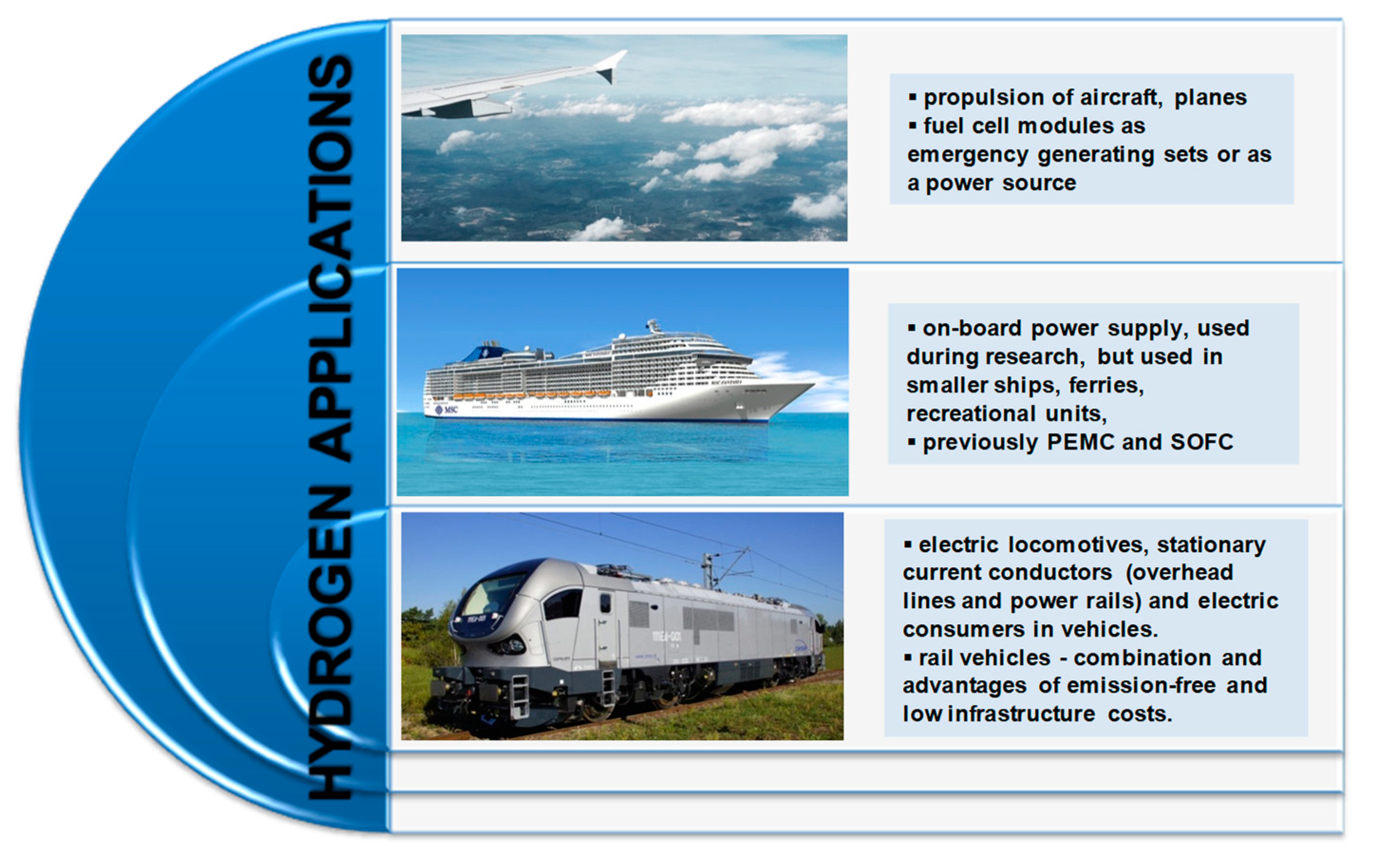
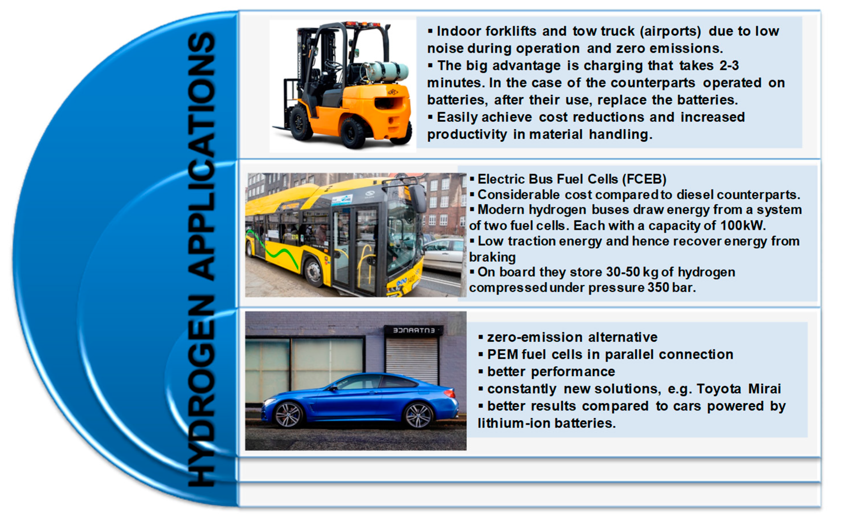
Figure 5 shows hydrogen applications; the most common are aircraft, planes, on-board power supply, electric locomotives, indoor forklifts and electrobuses.
The eco-revolution in the automotive industry has been taking place for several years. Manufacturers, forced by restrictive EU regulations on the permissible level of exhaust emissions and the changing expectations of conscious customers, are working intensively on the development and laborious introduction of alternative power sources for passenger cars and trucks to the world markets [40,41,42]. The problem is still the limited functionality of hybrid vehicles and a modest network of fast charging points dedicated to electric cars. Hybrid cars are most efficient only in urban conditions. Where frequent starts, stops and long and slow driving in traffic jams are common, the cooperation of the combustion engine and electric engine offers the greatest benefits and results. Electric energy stored in batteries during braking, operation of an internal combustion unit or charging from a household socket is used only for covering several or several dozen kilometers in city traffic in zero-emission mode.
One type of alternative fuel propulsion system is the so-called hybrid systems. These use fuel cells instead of an internal combustion engine. The division of fuel cells reflects the type of electrolyte used. Thus, it determines at which temperatures the reactions in the cell occur. Fuel cells differ in the structure of the materials used in their construction and the efficiency of energy generated depending on the type of fuel. Any type of cell has both advantages and disadvantages.
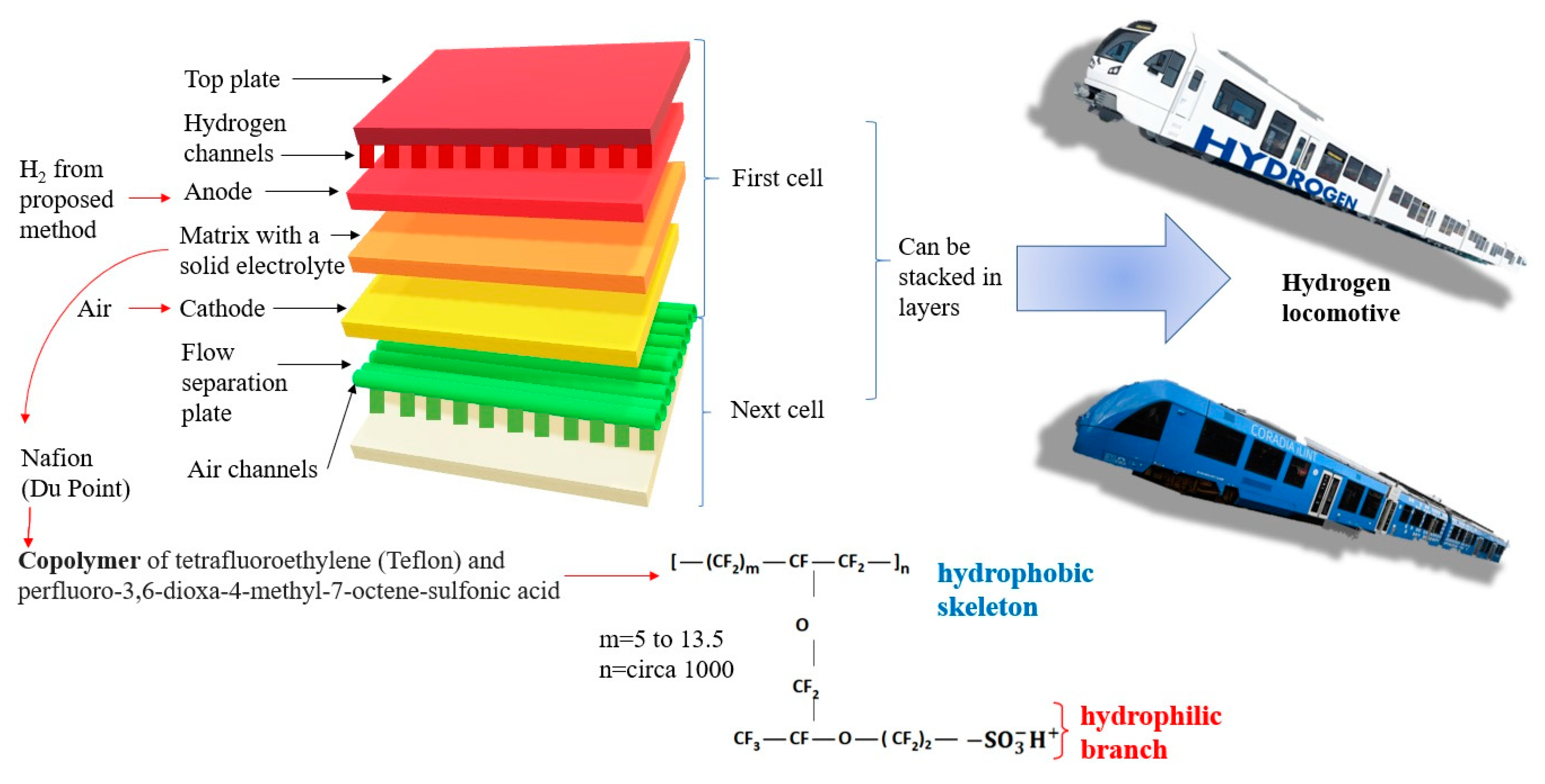
PEM fuel cells (proton exchange membrane or polymer electrolyte membrane) are driven by hydrogen with high purity. The fuel cell consists of two electrodes: anode and cathode. The electrodes are separated by electrolyte in liquid or solid form. Classification criterion cells are a type of electrolyte and, in the case of a PEM cell, the electrolyte is a special membrane that allows only positive hydrogen ions (protons) to pass through, hence the abbreviation PEM, from the English name Proton Exchange Membrane Fuel Cell. The electrolyte allows the flow of cations but prevents the flow of electrons. The chemical reaction that takes place in the cell consists of breaking the hydrogen into a proton and an electron at the anode, and then joining the reactants at the cathode. Electrochemical processes are accompanied by the flow of an electron from the anode to the cathode, bypassing the impermeable membrane. The electrochemical reaction of hydrogen and oxygen produces electricity, water and heat. The fuel—pure hydrogen or hydrogen mixed with other gases—is fed continuously to the anode, and the oxidant—pure oxygen or a mixture (air)—is fed continuously to the cathode. Nafion, which is a polymeric material, acts as a membrane. It is characterized by high efficiency in electricity production (up to 65%) and a slightly exothermic process. These aspects result from the low reaction temperature in the chamber of −60–100 °C.
In an alkaline fuel cell (AFC), the electrolyte is an aqueous alkaline solution, most commonly potassium hydroxide (KOH). The cell, in which 85% KOH solution is used, works at a temperature of 250 °C, while if the concentration of KOH solution is 35–50%, the cell operating temperature is lower, at 120 °C. The catalyst of the reaction can be nickel (Ni), silver (Ag), tungsten compounds, metal oxides or precious metals (e.g., platinum). The anode is a mesh or porous nickel with a maximum pore diameter of 16 μm on the electrolyte side and 30 μm on the gas side, while the cathode is porous lithium nickel oxide NiO with Ag. The fuel is hydrogen (H2) and the oxidant is oxygen (O2). Efficiency is 50% at an ambient temperature of 20 °C.
DMFC (Direct Methanol Fuel Cell) has a polymer membrane such as PEM. The difference lies in the construction of the anode. In the DMFC cell, internal reforming of methanol is allowed. Here, the as-obtained hydrogen is used to power up the cell. There are also no difficulties with fuel storage. It is also practical for mobile use due to the low reaction temperature (approx. 80 °C). The DMFC cell has lower efficiency compared to the PEM cell (equal to 40%).
PAFC (Phosphoric Acid Fuel Cell) cells are used to form electricity and heat cogeneration systems. The efficiency of electricity production is the same as in the DMFC. Moreover, the water vapor produced may be converted into heat. The electrolyte in the PAFC cell is phosphoric acid (H3PO4). The advantage of the cells is high tolerance to carbon monoxide. This allows the application of different fuels (however, the desulphurization process of fuel is significant).
In MCFC (Molten Carbonate Fuel Cell), the electrolyte is Li/K carbonate (in a molten state). These are high-temperature fuel cells that operate at temperatures of 600 °C and above. Molten Carbonate Fuel Cells (MCFCs) are currently being developed for natural gas, biogas (produced by anaerobic fermentation or gasification of biomass) and coal-based power plants for electrical utility, industrial and military applications. MCFCs are high-temperature fuel cells that use an electrolyte consisting of a molten mixture of a carbonate salt suspended in a porous, chemically inert ceramic matrix of beta-alumina solid electrolyte. Since they operate at extremely high temperatures of 650 °C and above, base metals can be used as anode and cathode catalysts, reducing operation costs.
In SOFC cells (Solid Oxide Fuel Cell), the separator is created with oxide ceramics. The temperature range of operation is high and amounts to 650–1000 °C. As a result, in cogeneration systems, they achieve high efficiency of electricity and heat (up to 85%). The disadvantage is the start-up and shutdown time of the cells, which translates into their use in stationary CHP systems (heat and energy cogeneration). SOFCs show a high tolerance to fuel pollutants: carbon monoxide and sulfur compounds.
Considering the operational parameters of the cells in terms of their application as the power supply systems of transport drive systems, it is important to consider high efficiency in generating electricity and the short start and stop times of the cell.
Among the presented fuel cells, PEM and AFC cells have properties that allow them to be used in future drive modes of transport. Their efficiency in generating energy is in the range of 35% to 70%, and the working temperature for PEM cells is 60–100 °C and for AFC cells 100–250 °C (Table 3). These cells are powered by hydrogen; therefore, if we wish to use methanol as the fuel supplying the cell, it is necessary to use additional external reforming systems. In terms of energy parameters and the possibility of supplying various fuels, SOFC cells are an interesting solution. In their application, however, there is an operational problem related to the required continuity of work.
In recent years, the process of burning fossil fuels has been criticized due to the emission of greenhouse gases, especially carbon dioxide. The energy industry is seeking alternative, environmentally friendly energy sources. The combustion of hydrogen in heat engines does not generate harmful emissions of carbon monoxides and hydrocarbons (apart from the inevitable burning of some of the lubricating oil), but still produces nitrogen oxides due to the high combustion temperature. One solution to the problem of nitrogen oxide emissions is the use of fuel cells capable of converting the chemical energy of hydrogen into electricity without combustion in the working chamber. To properly control the working process of the fuel cell, it is necessary to properly control not only the fuel (hydrogen) dosing but also the oxygen (air) dosing.
Currently, the most promising and most intensively developed type of fuel cells is a PEM (Proton Exchange Membrane) cell, which provides results an order of magnitude greater than other fuel cells, with the exception of the highly advanced Alkaline Fuel Cells (AFC) used in space technology. PEM cells can be powered by pure hydrogen or reformed hydrocarbon fuel. Cold weather capability allows them to get started quickly. The very small thickness of the membrane–electrode assembly allows for a compact construction of this type of cell. Another advantage is the lack of chemically aggressive fluids that can cause corrosion and the fact that the cell can operate in any geometric orientation. These advantages confirm the possibility of using PEM fuel cells for both automotive and portable applications.
The high involvement of research teams has resulted in a reduction of costs so that PEM cells are currently the cheapest of all types of cells.
PEM fuel cell stacks are also used in commercial car drives. The acid membrane, which has the ability to conduct protons, consists of a Nafion material. As there are electrochemical reactions in the fuel cell, it is important to use a catalyst (platinum black). The platinum black catalyst material is deposited on carbon paper or fabrics that are positioned on both sides of the cell. The disadvantage of the platinum anode is the aggressive reaction of carbon monoxide with the catalyst—it lowers the catalytic properties.
Figure 6 shows the reactions taking place both at the cathode and at the anode (hydrogen gas is fed to the anode of the fuel cell, and humidified air passes through the cathode).
The disadvantages of virtually all types of fuel cells include:
  • The production of fuel cells is expensive due to the use of expensive construction materials with specific properties. Cheap substitutes for these materials are difficult to find;
  • Fuel production technology is expensive and complex and requires additional energy;
  • When using fuels other than hydrogen, the operating efficiency gradually decreases. This is caused by electrolyte degradation and poisoning of catalysts.
The great challenge in this type of fuel cell is heat and water management. A significant increase in the temperature of the cell itself was observed as a result of the occurrence exothermic reactions. PEM fuel cells are widely used in the transportation and automotive industries.
SOFCs have the advantage that they can use diesel fuel to power them without having to process fuel to obtain pure hydrogen. The electrical efficiency of a conventional on-board generator in a vehicle is around 10–15%. The electrical efficiency of the SOFC cell is currently around 30%, which is twice the standard solution. Emission of harmful compounds and noise are lower than in the case of operation of propulsion systems powered by internal combustion engines. The overall efficiency of the system is higher due to the heat generated by the operation of the fuel cell. One of the solutions obtained as part of the work carried out in this area is a study presented jointly by AVL and NISSAN as an SOFC Auxiliary Power Unit (SOFC APU). This is a solution based on the use of the SOFC as a battery charging system (with a maximum energy of 24 kWh) Li-Ion in a vehicle with its own ms of up to 3.5 tonnes. The e-NV200 model uses a 5 kW SOFC cell powered by ethanol or a mixture of ethanol and water (55% water, 45% ethanol). As a result of internal reforming of the supplied fuel, hydrogen is obtained, which feeds the cell. The range of a vehicle equipped with such a support system solution is around 600 km. The disadvantage of this solution is the production of carbon monoxide during methanol reforming. Its presence is associated with the efficiency of the methanol steam reforming process and is around 70–80%. The presence of carbon monoxide is unfavorable due to the impact on the cathode surface, which, when switching off the cell, can lead to its so-called oxide treatment, which, with the repeated process of starting and stopping the cell, causes deterioration of its efficiency. Ascend Energy together with the manufacturer of SOFC Atrex Energy cells offer a tubular fuel cell for ATVs (all-terrain vehicles). The cell uses a conventional hydrocarbon fuel such as natural gas, propane or LPG without an external reformer system. No hydrogen storage is therefore required in the vehicle. The cell operates at a temperature of 600–800 °C, generating 4.5 kW.
The components of a polymer stack fuel cell are presented in Figure 7. This figure also shows the structure of Nafion, which is the most commonly used solid electrolyte and PEM membrane.
Despite the global energy demand, the willingness to protect the environment from pollution has made hydrogen a realistic alternative to traditional fossil fuels. Hydrogen is the most abundant element in the universe, and therefore is an endless and renewable energy source [43,44]. In addition, hydrogen may be obtained from renewable and sustainable resources, making it environmentally hopeful. Hydrogen is also produced from biomass and can be a low-cost approach thanks to the use of supercritical water gasification [45] and fermentation methods [43]. This fuel could also be obtained using solar energy [46,47,48]. Hydrogen has the highest gravimetric energy density (among non-nuclear fuels) and can easily be transformed into heat, mechanical and electrical energy [49]. A promising way to use electricity and heat without impacting the environment is their use in both stationary and automotive applications. This paves the way for new possibilities in the field of sustainable energy use worldwide [49,50,51,52].
It is also worth mentioning other technical solutions which have been widely analyzed.
In [53], the authors presented an energy management strategy for hybrid electric buses (HEB). The main topic was thermal stability and driving costs, while the degradation of the lithium-ion battery (LIB) was also focused on. There is an emphasis on multilateral indicators, so the least costly and comprehensive pathways are presented to focus on increasing penalties and the cost of LIB degradation and overheating.
The authors of [54] propose an energy management strategy based on machine learning for HEB. The Deep Deterministic Policy Gradient (DDPG) algorithm was used to increase the cold start efficiency and optimize HEB power allocation. It is linked to the expert help system. As in [1], penalties are applied for overheating and degradation of the battery. This method is used in various road missions to show that it is superior in terms of maintaining adequate performance, efficiency and optimization.
It should be noted that there are many other modern methods of energy management in HEB. This includes a combination of deep support learning (DRL) and transfer learning (TL). This is to remove DRL defects. In the first step, the optimization of the hybrid tracked vehicle is modeled. This is done by placing complex components of the driveline. An energy management strategy (EMS) needs a two-tier control framework. There are two levels: higher and lower. Higher requires the Deep Deterministic Policy Gradient (DDPG) algorithm. With this method, it is possible to control the EMS at different speed intervals. The TL method is used to create the appropriate drive cycle by transforming neural networks (lower level). After a series of tests, it was confirmed that the submitted control policy with DRL and TL enabled is able to increase energy efficiency and improve the efficiency of the entire system [55].

3.3. Enzymatic Pretreatment of Cellulosic Materials

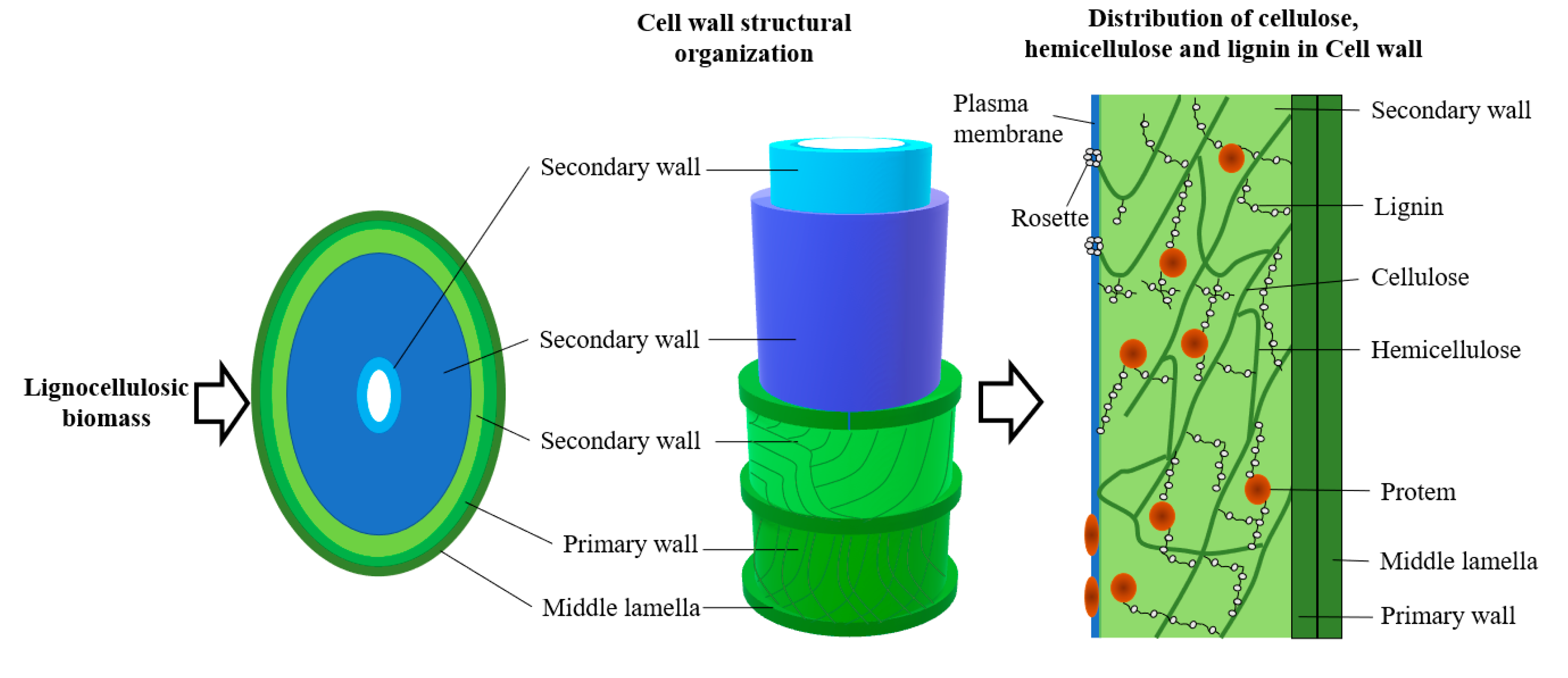
Lignocellulose is the main component of plant biomass, composed of three parts—lignin, cellulose and hemicelluloses [56]. While lignin is currently mainly suitable for fuel in the energy industry, or as an additive to fertilizers, many sugars can be obtained from cellulose and hemicelluloses that can be used in biotechnology—for example, as a source of energy for microorganisms. However, before this is possible, the material must undergo special treatment.
The molecular weights of the first three parts are high and they are dense, while the molecular size of the last component is small and sparse [57]. Cellulose, which is a glucose polymer, can be enzymatically broken down into its monomer, which is the primary source of energy for bacteria and can therefore be used as, for example, a nutrient component. Hemicelluloses are a heterogeneous group of polysaccharides that can vary significantly in composition depending on the source. Sealre et al. [58] found that a large amount came from uneaten food and garden clippings (lawn, tree branches, etc.). It is worth remembering that cellulose and hemicelluloses are not the only polysaccharides that can be found in waste materials from biomass production. They can also contain carbohydrates such as starch or pectin, which can also be a good source of energy for microorganisms.
A schematic framework of lignocellulosic biomass is shown in Figure 8.
The production of cellulose by the hydrolysis method involves the repetition of secondary impurities. Cellulose-hydrolyzing enzymes are directly involved in the enzymatic hydrolysis of cellulose and have an important role in the biological treatment of cellulose. It can be carried out directly or by a microbiological and enzymatic method (hydrolyzes crystalline/amorphous cellulose to fermentable sugars) [59].
The relationship between hydrolytic enzymes and cellulose-derived substrates is widely interpreted: it is possible that they interact in the system of a complex of mulitenzymes and insoluble biomass substrates (catalytic action) [60].
Enzymatic hydrolysis has many advantages and disadvantages. The advantages include low energy requirements, unstressed reaction conditions and high yields of sugars and the hydrolysis process itself.
In turn, among the disadvantages, one should mention the very low speed, especially in comparison with other chemical processes, or the cost of the enzymes themselves (which translates into the entire economy of the process).
This method distinguishes three characteristic stages:
-
adsorption process on the cellulose surface;
-
process of biodegradation of cellulose to sugars;
-
cell desorption process.
Any changes at each of these steps may result in an irreversible adsorption of cellulose to cellulose [61]. Using the popular chemical pretreatment, crystallizing, among others, acid or alkali may change the crystal structure of lignocellulose itself and thus “open” it to easier access of enzymes to convert polysaccharides into fermentable sugars [62]. It has been proven that high temperature also increases the penetration of enzymes.
The addition of surfactants (e.g., Tween 20 and Tween 80) during hydrolysis can alter the nature of the surface properties of the cellulose.
In the literature, it can be found that the addition of polymers is promising (polyethylene glycol), affecting the efficiency of enzymatic lignocellulose hydrolysis (it has a direct impact on the availability of enzymes for cellulose degradation) [63]. A very important role is played by additives that are added directly to lignin, e.g., bovine serum albumin. Saratale et al. [64] reported that the addition of certain metal additives, such as Mn2, can effectively enhance the multicomponent cellulase enzyme system in Cellulomonas biaoteaNCIM-2550.
Numerous studies have been conducted to determine the structure and mechanism of cellulase action. All of this was aimed at increasing the profitability of the production of the cellulase enzyme.

3.4. Gasification

Biomass is a source of primary energy consisting of all substances of plant and/or animal origin that are biodegradable and whose use for energy purposes is not restricted by law. Biomass is used often for the generation of heat and biofuels.
Taking into account the current trends in technologies using biomass for energy purposes (relatively low conversion efficiency), it can be assumed that, in the future, the use of cogeneration (electricity and heat production in one process) and trigeneration (electricity, heat and cold energy production in one process) can significantly improve the management of biomass resources.
Biomass is primarily used to produce heat and biofuels. Biomass gasification generally refers to the thermochemical conversion of solid fuels from biomass using a gasifying agent (e.g., vapors, air (partial oxidation) or CO2) to a mixture of flammable gaseous products including H2, CH4, CO and CO2. Gasification is one of the most efficient ways of extracting energy from fuel sources and converting it into a usable form by converting solids partially or completely into gases. It is an energy conversion process that has been explored as an alternative solution to environmental problems related to energy production [65]. Gasification of biomass is the earliest and most economical way to produce renewable H2. Biomass is used for energy purposes in the processes of direct combustion, co-combustion of solid biofuels, converted into liquid fuels or subject to gasification. The conversion of biomass into energy carriers can be achieved by one of three methods: physical, chemical and biochemical. Depending on the dominant output of this process, which may be gas, liquid fuel or solid fuel, this process is called incineration, co-incineration, gasification, pyrolysis or a biochemical process. Combustion is used for the production of thermal energy as well as for the production of electricity and is the most common and, at the same time, the simplest form of obtaining energy from biomass. Worldwide, as much as 90% of energy obtained from biomass is generated in the combustion process, and biomass can be burned in all states of matter. In order for wood to be burned as efficiently as possible, while meeting environmental standards, it is recommended that it proceed in three phases: drying and degassing of wood material, resulting in the formation of wood gas, wood gas combustion at a temperature of 1200 °C, gas afterburning and heat dissipation in exchanger.
For ecological, efficient combustion of biomass in order to obtain energy, specifically designed boilers are used, equipped with combustion chambers with fixed or movable grates and characterized by an increased heat exchange surface. The effectiveness of the combustion process depends on the amount of air supplied. In modern boilers, the combustion air is supplied in the form of so-called primary and secondary air. Primary air is mixed with fuel and used in the gasification and combustion of charcoal. Secondary air, on the other hand, is used for the combustion of volatile substances and it does not mix with the primary air. Combustion installations can be used to utilize various types of biomass, including lump wood, wood chips, sawdust and straw. Due to the physico-chemical properties of biomass, appropriate technological solutions should be used, tailored to the specific type of fuel. The greatest complications are the differences in the proportions of solid and volatile compounds in wood and fossil fuels (hard coal, brown coal, coke) and high biomass moisture.
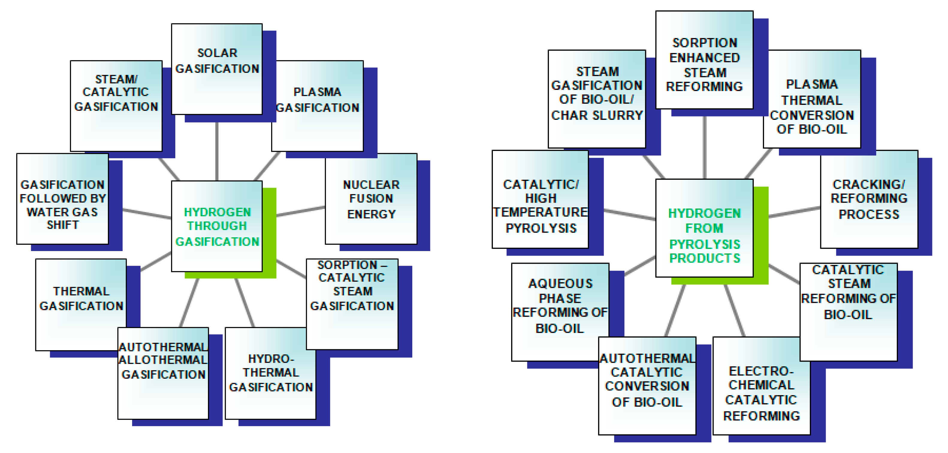
Gasification of biomass is a two-stage pyrolysis method. It is obviously followed by gasification. Pyrolysis is the decomposition of biomass raw material under the influence of heat. This step, also known as degassing, is endothermic. In this process, 75% to 90% of the volatile materials in the form of gaseous and liquid hydrocarbons is generated. The remaining non-volatile material with a high carbon content is called char [66] (Figure 9).
The volatile hydrocarbons and char are subsequently converted to syngas in the second step—gasification. A few of the major reactions involved in this step are listed here [66]. In the presence of an oxidizing agent at high temperature, the large polymeric molecules of biomass decompose into lighter molecules and eventually to permanent gases (CO, H2, CH4 and lighter hydrocarbons), ash, char and tar and minor contaminants. Char and tar are the result of the incomplete conversion of biomass. Several methods of biomass gasification are described in the following sections.
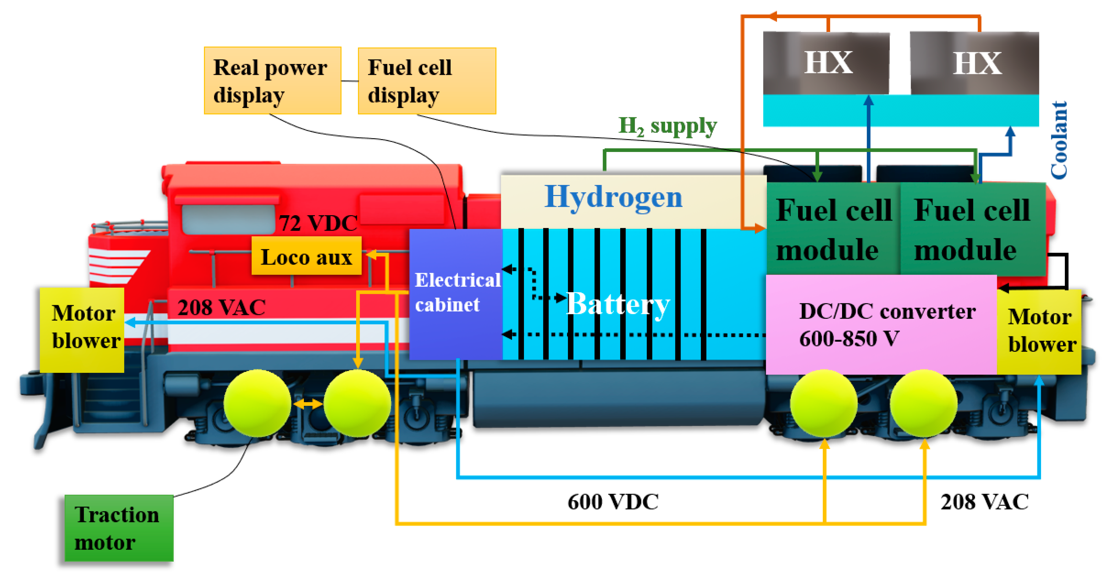
Miller et al. [67] created the entire system for the locomotive (Vehicle Projects LLC) described earlier. The proposed system layout is shown in Figure 8. First of all, the work cycle of the switch locomotive was taken into account in order to investigate the power demand as a function of time during various modes of the locomotive operation.
In the next stage, the vehicle system was addressed with subsystems embedded in the vehicle, hydrogen storage and cooling, and finally, the control system was focused on. It demonstrated 300 kW gross and 624 VDC.
Hoffrichter et al. [68] focused on hydrogen propulsion for use in building a hybrid locomotive. The idea involved the use of PEM fuel cell technology, which used hydrogen fuel to generate the power used to power batteries or traction motors. Lead acid batteries were used. The prototype was operated and tested at various speeds from 2 to 10 km/h. It was found that the efficiency of the power system was in the range of 2–40%. The locomotive prototype was designed with a power system that used fuel cell energy with near-average energy demand and battery power when power demand was high.
Peng et al. [69] also focused their research on a hydrogen-powered locomotive. Their research, however, was aimed at reducing the environmental impact of traditional technologies.
Tests of the developed prototype were carried out in China.
The advantage is that they are not harmful to the environment and have relatively low infrastructure costs.
It is well known that hydrogen fuel storage uses readily available equipment and proven safety systems. First, by mounting the two modules, the core is mounted above the traction battery (see Figure 10). Each has seven carbon/aluminum tanks with specific specifications. Fuel is supplied by the system in cyclic operation for around 9 h. The system is designed to have a tank with a relief valve, a pressure limiting device (PRD), a thermocouple (or other temperature sensor) and a solenoid valve. A safety element has been introduced so that when the conduit between the tank and the distribution manifold is broken, the tank’s overflow valve will close. Limited operation of the battery at elevated temperature, which may self-ignite, has also been noticed. Hence, the thermally activated PRDs will vent the tank contents through a vent line directed upwards and away from the vehicle. Temperature sensors have been installed to warn of excessive temperature.
A collector is installed in each module. It is primarily fed from each tank. At the next stage, the modular collectors contain individual pressure sensors, which are connected to the main distribution line [67]. The main distribution line connects to the fuel line and then goes to the filter, pressure regulator, additional electronic solenoid valve, pressure sensor and additional PRD. The introduction of an additional solenoid valve facilitates the possibility of switching off (pressure sensor verifies the operation of the regulator). The diagram of emergency installation of the cut-off device is similar to that in diesel locomotives, i.e., it is easier for tank personnel to switch off the fuel system.
4. Conclusions

Research and development works carried out in recent years in the field of mass transport (rail and road) concern, in particular, the reduction of the harmful impact of vehicles on the natural environment—reduction of the emission of toxic pollutants in engine exhaust gases. In addition, taking into account the high prices of fuels used as a source of energy in internal combustion traction vehicles and road utility vehicles, one should definitely strive to reduce their consumption and thus increase the efficiency of transport.
The purchase of modern rolling stock is among the methods that enable the above-mentioned efficiency improvement in the mass transport of passengers and cargo. New vehicles from production lines to transport companies are able to ensure not only a high level of efficiency but also the high safety of these transports. This is mainly due to the use of modern and efficient propulsion systems in means of transport, including hybrid ones, which were the essence of this article.
The aim was to present alternative drives against the background of classic drives in common use. As can be seen, the main problem with the former is the relatively short range of the vehicle and the need to allow access to the refueling network. Therefore, large financial outlays are made for specialized railway infrastructure. However, alternative drives bring significant environmental benefits. Therefore, it is difficult to clearly define what type of drive system should be used when constructing new railway vehicles.
In order to meet changing regulatory standards and future environmental and energy goals, it is important to understand that our customers will be successful in the long term. We must offer a wide range of products powered by multiple energy sources. Providing hydrogen fuel cell solutions takes us one step further towards meeting the changing needs of our customers—that is the goal of the institute.
The issue discussed in the article is the potential to reduce the energy consumption of the produced fuel. The following issues were discussed: minimization of environmental pollution due to unused gasification methods, during which compounds such as CH4, CO2 are produced, which are not indifferent to health and the planet; decarbonization of transport via the use of industrial energy, which is a raw material using captured carbon; application of biological and enzymatic methods; biomass as a source of alternative energy and low-emission fuel; carbohydrates (starch and cellulose) as abundant, renewable bio-sources; implementation of the concepts of “Green Chemistry” as a result of the use of waste (low-cost materials) and naturally occurring raw materials. The resulting hydrogen can be used directly in both internal combustion engines and fuel cells (fuel cell systems) due to the lack of further conversions, obtaining material with specific properties and the ability to control microstructure and morphology.

Author Contributions

Conceptualization, P.D.; methodology, P.D., B.K., M.P.; validation, M.A.; formal analysis, P.D., B.K., M.P.; investigation, P.D.; resources, P.D., B.K., M.P.; data curation, P.D., B.K., M.P.; writing—original draft preparation, P.D., B.K., M.P.; writing—review and editing, P.D.; supervision, M.A. All authors have read and agreed to the published version of the manuscript.

Funding

This research received no external funding.

Institutional Review Board Statement

Not applicable.

Informed Consent Statement

Informed consent was obtained from all subjects involved in the study.

Data Availability Statement

Analysis was performed in Łukasiewicz Research Network–Rail Vehicles Institute “TABOR”.

Conflicts of Interest

The authors declare no conflict of interest.

References

  1. Pielecha, I.; Merkisz, J.; Andrzejewski, M.; Daszkiewicz, P.; Świechowicz, R.; Nowak, M. Ultracapacitors and fuel cells in rail vehicle drive systems. Rail Veh. 2019, 1, 1–5. [Google Scholar]
  2. Andrzejewski, M.; Gallas, D.; Daszkiewicz, P.; Merkisz-Guranowska, A.; Stawecka, H. The latest technical solutions in rail vehicle drives. MATEC Web Conf. 2017, 118. [Google Scholar] [CrossRef]
  3. Advances in Chemical Engineering. 2012. Available online: https://www.sciencedirect.com/bookseries/advances-in-chemical-engineering (accessed on 20 February 2021).
  4. Fuel Cell Mine Locomotive Passes Initial Tests. 2002. Available online: https://www.sciencedirect.com/science/article/abs/pii/S1464285902100162 (accessed on 20 February 2021).
  5. Consortium to Develop Fuel Cell Locomotive. 2003. Available online: https://www.sciencedirect.com/science/article/abs/pii/S1464285903010034 (accessed on 20 February 2021).
  6. Design Milestone for Fuel Cell Locomotive. 2004. Available online: https://www.sciencedirect.com/science/article/abs/pii/S1464285904001439 (accessed on 20 February 2021).
  7. Contract to Develop Fuel Cell Power for Rail Vehicle. 2005. Available online: https://www.sciencedirect.com/science/article/abs/pii/S1464285905708154 (accessed on 20 February 2021).
  8. Japanese Train Company to Test World’s First Fuel Cell Passenger Train. 2006. Available online: https://www.sciencedirect.com/science/article/abs/pii/S146428590671077X (accessed on 20 February 2021).
  9. BNSF, Vehicle Projects Demonstrate Fuel Cell Switch Locomotive I. 2009. Available online: https://www.sciencedirect.com/science/article/abs/pii/S1464285909702457 (accessed on 20 February 2021).
  10. Anglo American Fuel Cell Mine Locomotive in South Africa. 2012. Available online: https://www.sciencedirect.com/science/article/abs/pii/S1464285912701463 (accessed on 20 February 2021).
  11. US–SA Partnership to Produce Five Fuel Cell Mine Locomotives. 2012. Available online: https://www.sciencedirect.com/science/article/abs/pii/S146428591270038X (accessed on 20 February 2021).
  12. Alstom Unveils Coradia iLint Hydrogen Fuel Cell Powered Train for European Regional Market. 2016. Available online: https://www.sciencedirect.com/science/article/abs/pii/S1464285916302280 (accessed on 20 February 2021).
  13. Indian Railways in Project to Develop Fuel Cell Powered Train. 2018. Available online: https://www.sciencedirect.com/science/article/abs/pii/S1464285918300750 (accessed on 20 February 2021).
  14. Rymaniak, Ł.; Lijewski, P.; Kamińska, M.; Fuć, P.; Kurc, B.; Siedlecki, M.; Kalociński, T.; Jagielski, A. The role of real power output from farm tractor engines in determining their environmental performance in actual operating conditions. Comput. Electron. Agric. 2020, 173, 105405. [Google Scholar] [CrossRef]
  15. Midilli, A.; Ay, M.; Dincer, I.; Rosan, M.A. On hydrogen and hydrogen energy strategies I: Current status and needs. Renew. Sustain. Energy Rev. 2005, 9, 255. [Google Scholar] [CrossRef]
  16. Holladay, J.D.; Hu, J.; King, D.L.; Wang, Y. An overview of hydrogen production technologies. Catal. Today 2009, 139, 244. [Google Scholar] [CrossRef]
  17. Turner, J.; Sverdrup, G.; Mann, M.K.; Maness, P.-C.; Kroposki, B.; Ghirardi, M.; Evans, R.J.; Blake, D. Renewable hydrogen production. Int. J. Energy Res. 2008, 32, 379. [Google Scholar] [CrossRef] [Green Version]
  18. Levin, D.B.; Chahine, R. Challenges for renewable hydrogen production from biomass. Int. J. Hydrogen Energy 2010, 35, 4962–4969. [Google Scholar] [CrossRef]
  19. Eroğlu, İ.; Tabanoğlu, A.; Gündüz, U.; Eroğlu, E.; Yücel, M. Hydrogen pro-duction by Rhodobacter spheroides O.U.001 in a flat plate solar bioreactor. Int. J. Hydrogen Energy 2008, 33, 531. [Google Scholar] [CrossRef]
  20. Seifert, K.; Waligorska, M.; Laniecki, M. Hydrogen generation in photobio-logical process from dairy wastewater. Int. J. Hydrogen Energy 2010, 35, 9624. [Google Scholar] [CrossRef]
  21. Seifert, K.; Waligorska, M.; Laniecki, M. Brewery wastewaters in photobiolo-gical hydrogen generation in presence of Rhodobacter spheroides O.U.001. Int. J. Hydrogen Energy 2010, 35, 4085. [Google Scholar] [CrossRef]
  22. Boran, E.; Özgür, E.; van der Burg, J.; Yücel, M.; Gündüz, U.; Eroglu, I. Bio-logical hydrogen production by Rhodobacter capsulatus in solar tubular photo bioreactor. J. Clean. Prod. 2010, 18, 529. [Google Scholar] [CrossRef]
  23. Sabourin-Provost, G.; Hallenbeck, P.C. High yield conversion of a crude glycerol fraction from biodiesel production to hydrogen by photofermentation. Bioresour. Technol. 2009, 100, 3513. [Google Scholar] [CrossRef]
  24. Jayasinghearachchi, H.S.; Sarma, P.M.; Lal, B. Biological hydrogen production by extremely thermophilic novel bacterium Thermoanaerobacter mathranii A3N isolated from oil producing well. Int. J. Hydrogen Energy 2012. [Google Scholar] [CrossRef]
  25. Chen, C.-C.; Chuang, Y.-S.; Lin, C.-Y.; Lay, C.-H.; Sen, B. Thermophilic dark fermentation of untreated rice straw using mixed cultures for hydrogen pro-duction. Int. J. Hydrogen Energy 2012, in press. [Google Scholar] [CrossRef]
  26. Lay, J.-J.; Lee, Y.-J.; Noike, T. Feasibility of biological hydrogen production from organic fraction of municipal solid waste. Water Res. 1999, 33, 2579. [Google Scholar] [CrossRef]
  27. Van Ginkel, S.W.; Logan, B. Increased biological hydrogen production with reduced organic loading. Water Res. 2005, 39, 3819. [Google Scholar] [CrossRef] [PubMed]
  28. Moritz, M. Biological methods for obtaining hydrogen. Chemik 2012, 66, 827–834. [Google Scholar]
  29. Rand, D.; Dell, R.M. Hydrogen Energy—Challenges and Prospects; RSC Publishing: Cambrigde, UK, 2008. [Google Scholar]
  30. Jones, L.W. Toward a Liquid Hydrogen Fuel Economy; Engineering Technical Report UMR2320; University of Michigan: Ann Arbor, MI, USA, 1970. [Google Scholar]
  31. Kozłowski, K.; Dach, J.; Lewicki, A.; Cieślik, M.; Czekała, W.; Janczak, D.; Smurzyńska, A.; Carmona, P.C.R. Biologiczne Sposoby Produkcji Wodoru; Uniwersytet Przyrodniczy w Poznaniu, Instytut Inżynierii Biosystemów: Kraków, Poland, 2016; pp. 26–28. [Google Scholar]
  32. Rögner, M. Biohydrogen; De Gruyter: Berlin, Germany; Monachium, Germany; Boston, MA, USA, 2015. [Google Scholar]
  33. Venkata, M.S.; Pandey, A. Biohydrogen Production: An Introduction in Biohydrogen; Pandey, A., Chang, J.-S., Hallenbeck, P.C., Larroche, C., Eds.; Elsevier: Amsterdam, The Netherlands, 2013. [Google Scholar]
  34. Das, D.; Veziroglu, T.N. Advances in biological hydrogen production processes. Int. J. Hydrogen Energy 2008, 33, 6046–6057. [Google Scholar] [CrossRef]
  35. Abbasi, T.; Abbasi, S.A. Renevable hydrogen: Prospects and challenges. Renew. Sustain. Energy Rev. 2011, 15, 3034–3040. [Google Scholar] [CrossRef]
  36. Adams, M.W.W.; Stiefel, E.I. Biological hydrogen production: Not so elementary. Science 1998, 282, 1842–1843. [Google Scholar] [CrossRef]
  37. McKendry, P. Energy production from biomass (part 1): Overview of biomass. Bioresour. Technol. 2002, 83, 37–46. [Google Scholar] [CrossRef]
  38. Nath, K.; Das, D. Hydrogen from biomass. Curr. Sci. 2003, 85, 265–271. [Google Scholar]
  39. De Vrije, T.; De Haas, G.G.; Tan, G.B.; Keijsers, E.R.P.; Claassen, P.A.M. Pretreatment of miscanthus for hydrogen production by Thermotogaelfii. Int. J. Hydrogen Energy 2002, 27, 1381–1390. [Google Scholar] [CrossRef]
  40. Bajerlein, M.; Rymaniak, L. The reduction of fuel consumption on the example of ecological hybrid buses. In Applied Mechanics and Materials; Trans Tech Publications Ltd.: Dresden, Germany, 2014; Volume 518, pp. 96–101. [Google Scholar]
  41. Bajerlein, M.; Rymaniak, L.; Swiatek, P.; Ziolkowski, A.; Daszkiewicz, P.; Dobrzynski, M. Modification of a hybrid city bus powertrain in the aspect of lower fuel consumption and exhaust emissions. In Applied Mechanics and Materials; Trans Tech Publications Ltd.: Bäch, Switzerland, 2014; Volume 518, pp. 108–113. [Google Scholar]
  42. Kamińska, M.; Rymaniak, Ł.; Daszkiewicz, P.; Lijewski, P. Test guidelines for evaluation real driving emission two-way vehicles. In MATEC Web of Conferences; EDP Science: Les Ulis, France, 2019; Volume 294, p. 02009. [Google Scholar]
  43. Graetz, J. New approaches to hydrogen storage. Chem. Soc. Rev. 2008, 38, 73–82. [Google Scholar] [CrossRef]
  44. Carmo, M.; Fritz, D.L.; Mergel, J.; Stolten, D. A comprehensive review on PEM water electrolysis. Int. J. Hydrogen Energy. 2013, 38, 4901–4934. [Google Scholar] [CrossRef]
  45. Hosseini, S.E.; Wahid, M.A. Hydrogen production from renewable and sustainable energy resources: Promising green energy carrier for clean development. Renew. Sustain. Energy Rev. 2016, 57, 850–866. [Google Scholar] [CrossRef]
  46. Ausiello, A.; Micoli, L.; Turco, M.; Toscano, G.; Florio, C.; Pirozzi, D. Biohydrogen production by dark fermentation of Arundo donax using a new methodology for selection of H2-producing bacteria. Int. J. Hydrogen Energy 2017, 42, 30599–30612. [Google Scholar] [CrossRef]
  47. Lagorse, J.; Simões, M.G.; Miraoui, A.; Costerg, P. Energy cost analysis of a solar-hydrogen hybrid energy system for stand-alone applications. Int. J. Hydrogen Energy 2008, 33, 2871–2879. [Google Scholar] [CrossRef]
  48. Barbir, F. PEM electrolysis for production of hydrogen from renewable energy sources. Sol. Energy 2005, 78, 661–669. [Google Scholar] [CrossRef]
  49. Jain, I.P. Hydrogen the fuel for 21st century. Int. J. Hydrogen Energy 2009, 34, 7368–7378. [Google Scholar] [CrossRef]
  50. Edwards, P.P.; Kuznetsov, V.L.; David, W.I.F.; Brandon, N.P. Hydrogen and fuel cells: Towards a sustainable energy future. Energy Policy 2008, 36, 4356–4362. [Google Scholar] [CrossRef]
  51. Agbossou, K.; Chahine, R.; Hamelin, J.; Laurencelle, F.; Anouar, A.; St-Arnaud, J.-M.; Bose, T. Renewable energy systems based on hydrogen for remote applications. J. Power Sources 2001, 96, 168–172. [Google Scholar] [CrossRef]
  52. Edwards, P.P.; Kuznetsov, V.L.; David, W.I.F. Hydrogen energy. Philos. Trans. R. Soc. Lond Math. Phys. Eng. Sci. 2007, 365, 1043–1056. [Google Scholar] [CrossRef] [PubMed]
  53. Wu, J.; Wei, Z.; Li, W.; Wang, Y.; Li, Y.; Sauer, D. Battery Thermal- and Health-Constrained Energy Management for Hybrid Electric Bus based on Soft Actor-Critic DRL Algorithm. IEEE Trans. Ind. Informatics 2020. [Google Scholar] [CrossRef]
  54. Wu, J.; Wei, Z.; Liu, K. Battery-Involved Energy Management for Hybrid Electric Bus Based on Expert-Assistance Deep Deterministic Policy Gradient Algorithm. IEEE Trans. Veh. Technol. 2020, 69, 12786–12796. [Google Scholar] [CrossRef]
  55. Guo, X.; Liu, T.; Tang, B.; Tang, X.; Zhang, J.; Tan, W.; Jin, S. Transfer Deep Reinforcement Learning-Enabled Energy Management Strategy for Hybrid Tracked Vehicle. IEEE Access 2020, 8, 165837–165848. [Google Scholar] [CrossRef]
  56. Menon, V.; Rao, M. Trends in bioconversion oflignocellulose: Biofuels, platform chemicals &biorefinery concept. Prog. Energy Combust. Sci. 2012, 38, 522–550. [Google Scholar]
  57. Yaman, S. Pyrolysis of biomass to produce fuels and chemical feedstocks. Energy Convers. Manag. 2004, 4, 651–671. [Google Scholar] [CrossRef]
  58. Searle, S.; Malins, C. Availability of Cellulosic Residues and Wastes in the EU. 2013. Available online: https://theicct.org/publications/availability-cellulosic-residues-and-wastes-eu (accessed on 20 February 2021).
  59. Duff, S.J.B.; Murray, W.D. Bioconversion of forest products industry waste cellulosics to fuel ethanol: A review. Bioresour. Technol. 1996, 55, 1–33. [Google Scholar] [CrossRef]
  60. Rabinovich, M.L.; Melnick, M.S.; Bolobova, A.V. The Structure and Mechanism of Action of Cellulolytic Enzymes. Biochemistry (Moscow) 2002, 67, 850–871. [Google Scholar] [CrossRef]
  61. Converse, A.O.; Matsuno, R.; Tanaka, M.; Taniguchi, M. A model of enzyme adsorption and hydrolysis of microcrystalline cellulose with slow deactivation of the adsorbed enzyme. Biotechnol. Bioenginering 1988, 20, 38–45. [Google Scholar] [CrossRef]
  62. Mosier, N.; Wyman, C.; Dale, B.; Elander, R.; Lee, Y.Y.; Holtzapple, M.; Ladisch, M. Features of promising technologies for pretreatmentof lignocellulosic biomass. Bioresour. Technol. 2005, 96, 673–686. [Google Scholar] [CrossRef] [PubMed]
  63. Borjesson, P. Assessment of energy performance in the life-cycle of biogas production. Biomass Bioenergy 2006, 30, 254–266. [Google Scholar]
  64. Saratele, G.D.; Saratale, R.G.; Lo, Y.; Chang, J. Multicomponent Cellulase Production byCellulomonas biazoteaNCIM-2550 andIts Applications for Cellulosic Biohydrogen Production. Biotechnol. Prog. 2010, 26, 406–416. [Google Scholar]
  65. Boerrigter, H.P.; Calis, H.P.; Slort, D.J.; Bodenstaff, H.; Kaandorp, A.J.; Den Uil, H.; Rabou, L.P.; van Ree, R.; Veringa, H.J. Gas cleaning for integrated Biomass Gasification (BG) and Fischer-Tropsch (FT) Systems; Report C--04-056; Energy Research Centre of the Netherlands (ECN): Petten, The Netherlands, 2004. [Google Scholar]
  66. Bridgwater, A.V.; Evans, G.D. An Assessment of Thermochemical Conversion Systems for Processing Biomass and Refuse, ETSU (1993). Available online: https://www.osti.gov/etdeweb/biblio/10112623 (accessed on 20 February 2021).
  67. Miller, A.R.; Hess, K.S.; Barnes, D.L.; Erickson, T.L. System design of a large fuel cell hybrid locomotive. J. Power Sources 2007, 173, 935–942. [Google Scholar] [CrossRef]
  68. Hoffrichter, A.; Fisher, P.; Tutcher, J.; Hillmansen, S.; Roberts, C. Performance evaluation of the hydrogen-powered prototype locomotive “Hydrogen Pioneer P”. J. Power Sources 2014, 250, 120–127. [Google Scholar] [CrossRef] [Green Version]
  69. Eng, F.; Chen, W.; Liu, Z.; Li, Q.; Dai, C. System integration of China’s first proton exchange membrane fuel cell locomotive. Int. J. Hydrogen Energy 2014, 39, 13886–13893. [Google Scholar]
Figure 1. Technical requirements of fuel cell vehicle.
Energies 14 01144 g001
Figure 2. Directions of hydrogen technology.
Energies 14 01144 g002
Figure 3. Types of methods for obtaining hydrogen [15,16,17,18,19,20,21,22,23,24,25,26,27,28].
Energies 14 01144 g003
Figure 4. Diagram of the process of obtaining hydrogen by capturing hydrogen on the surface of carbon.
Energies 14 01144 g004
Figure 5. The use of hydrogen in various industries.
Energies 14 01144 g005aEnergies 14 01144 g005b
Figure 6. Diagram of the cell with different variants.
Energies 14 01144 g006
Figure 7. Proposition of a polymer cell for locomotives.
Energies 14 01144 g007
Figure 8. Composition of lignocelluloses.
Energies 14 01144 g008
Figure 9. Representative thermochemical methods of biohydrogen production from biomass.
Energies 14 01144 g009
Figure 10. An example of a hybrid locomotive system with fuel cells (HX—heat exchanger; DC—direct current) [31].
Energies 14 01144 g010
Table 1. Railroad development.
ProjectYearCharacteristicsReferences
Fuel Cell Propulsion Institute and Vehicle Projects LLC (limited liability company)2002Appr. 2 times more effective as compared to a battery locomotive. Additionally, vehicle was not equipped with traction battery; thus, the only power train was the fuel cell. Despite this, they exhibited satisfactory acceleration.[4]
Vehicle Projects LLC2003Capacity of 1000 kW, the largest vehicle powered by fuel cells (109 Tonnes). Furthermore, these were used to replace diesel-electric-based military locomotives and realization in a railway transport. [5,6]
Vehicle Projects LLC2005Power station, operating on PEM fuel cells at a capacity of 150 kW for railway application. [7]
JR East2006Hybrid diesel generator and hydrogen fuel-cell-powered passenger rail. It achieved a speed of 100 km/h. The main equipment comprised two fuel cells (capacity of 65 kW), battery and regenerative braking system.[8]
Vehicle Projects and BNSF Railway corporations2009Diesel-powered generator as a power source. A third of this power was obtained from fuel cells. Thanks to this, fully fuel-cell-operated locomotives were created.[9]
Hybrid system of Lithium ion battery packs and PEM fuel cell stacks in locomotive2012Cooperation between the US and South Africa in the development of mine locomotives powered with fuel cells. The fuel cell stack developer company Ballard Power Systems started collaboration with a Chinese railway company to develop advanced hydrogen fuel cells for tram applications.[10,11]
InnoTrans, the fuel cell-based train Coradia iLint (Alstom)2016Zero-emission vehicle. The locomotive with a hybrid fuel cell and battery system that utilized battery power. Battery was used during high accelerations. Its maximum speed was equal to 47 mph.[12,13]
Table 2. The occurrence of hydrogen in various industries.
ApplicationMethods of Hydrogen StorageExample
Fuel cell carCompressed gas 70 MPaToyota Mirai (2015)
Internal hydrogen system for cars with internal combustion engineLiquid hydrogen −232 °CBMW 7, sedane
Fuel cell busCompressed gas 70 MPaMercedes-Benz Citaro
Fuel cell bike/motorcycleCompressed gasPalcan, intelligent energy
LocomotiveLow-temperature hydridesmining locomotive, Dishaba Mine, South Africa
PlaneLiquid hydrogenBoeing Phantom-Eye
Fuel cell chargerLow-temperature hydridessmart energy, Upp and Horizon MiniPak portable chargers
Renewable energyLow-temperature hydridesSir Samuel Griffith Centre (30 MWh), Australia
Mixture: natural gas + hydrogen
(HCNG)
Compressed gas 70 MPa
Compressed gas
Project INGRID 39 MWh, Italy
ENEA Regione Emilia Romagna, Italy, natural gas buses-HCNG
SpaceshipsLiquid hydrogenGovernment space agencies of China, Europe, India, Russia, USA
Industrial gas distributionMedium-temperature hydridesHydrexia, Ni-Mg, MePhy hydrogen, Mg hydrogen
Table 3. Temperature limits of the systems used.
Cell TypeFuelT/°CEfficiency/%
PEMhydrogen60–10035–60
AFChydrogen100–25050–70
DMFCmethanol, methanol solution7535–40
PAFChydrogen21035–50
MCFChydrogen, methanol, methane, biogas, LPG65040–50
SOFChydrogen, methanol, methane, biogas, LPG650–100045–60
Publisher’s Note: MDPI stays neutral with regard to jurisdictional claims in published maps and institutional affiliations.