Article

Control of the Transformer Phase Powers Using a Single-Phase Voltage Source †

Faculty of Electrical Engineering, Automatics, Computer Science and Biomedical Engineering, AGH University of Science and Technology, 30-059 Kraków, Poland
*
Author to whom correspondence should be addressed.
This paper is an extended version of our paper published in 2020 12th International Conference and Exhibition on Electrical Power Quality and Utilisation (EPQU), Kraków, Poland, 14–15 September 2020.
Energies 2021, 14(4), 1038; https://doi.org/10.3390/en14041038
Submission received: 29 December 2020 / Revised: 1 February 2021 / Accepted: 12 February 2021 / Published: 16 February 2021

Abstract

:
Power flow in three-phase distribution grids containing single-phase prosumer voltage sources strongly depends on the RMS value of the voltage of these sources and their phase shifts in relation to the grid voltage. The ideal way to control single-phase prosumer sources should guarantee no return active power to the MV grid through a distribution transformer and no additional reactive power flows in the LV grid. This means that the active power of the one-phase voltage source is consumed by other single-phase customers (in the same phase or in other phases) and the reactive power of this source is equal to zero. The paper presents the results of the investigations of the dynamic control system of a single-phase voltage source that allows meeting these conditions. On the basis of steady-state calculations, the static characteristics of the above-mentioned control, needed to determine of the proper working point of a prosumer source were also obtained. The control process involves the control of the RMS value and phase angle of the voltage source against the phase voltage of the LV grid, to which the source is connected, with simultaneous control of the current phase angle issued by the power source against voltage. The result of the research is the confirmation of the necessity of using a zig–zag connection of the secondary side of distribution transformers. The developed control system of the prosumer voltage source does not fully control the active power of individual phases of the distribution transformer. The paper shows that the power losses in a distribution transformer strongly depend not only on the active power of the prosumer source, but also on its effective voltage and phase in relation to the transformer voltage.

1. Introduction

The issue of controlling the active and reactive powers of transformer phases is known in the literature. In [1], real and reactive power flows are independently controlled by injecting a compensating voltage in series with the transmission line from the transformer. Injection of the compensating voltage is realized through a “Sen Transformer” by controlling its voltage and phase angle. In [2], the configuration of a hybrid transformer is presented, which is to provide good energy quality in distribution grids integrating distributed generation from renewable energy sources (RESs) and non-linear loads. The proposed system covers a three-phase distribution transformer with secondary windings arranged as an open-end configuration and a three-phase inverter with a floating DC bus. This power conversion system can be exploited to perform a voltage control at the distribution grid edge, a reactive power management, and harmonic pollution mitigation. In [3], the effect of automatic voltage control (AVC) of a transformer on the quality of electric energy in the grid is discussed. The solution for online computation of the sensitivity of tapping point transformer voltage regulation, controlling the main transformer unloaded tap position and adjusting the AVC control parameters, are put forward. Authors suggested various methods of control, such as computing the sensitivity of tapping point voltage regulation online, resetting the no-load tap position of the main transformer, adjusting the AVC control parameters, or weakening the loss-reducing objective.
In this paper, instead of controlling the transformer phase voltages, controlling the amplitude and phase of the prosumer voltage is proposed. The control of power flows in the distribution grid with the use of single-phase RESs is something new. The authors present results of the simulation of control of the prosumer energy source, meeting the conditions of minimizing power losses in the transformer.
The issue of transformer operation with asymmetric or non-linear loads is known in the literature too [4,5,6,7]. The main purpose of these considerations is to determine the power losses in the transformer, active and reactive power flows, and transformer currents [8]. The issue of controlling single-phase inverters for RES appears mainly in application to their cooperation with single- or three-phase grids [9] or integration of multiple single-phase RESs and the control of power flow from them to single-phase electricity consumers and storage facilities [10]. Multi-winding single-phase transformers to which single-phase electricity sources, loads, and storages are connected are used in these situations [11]. Frequencies much higher than the mains 50/60 Hz are also often used [9,10], because all energy sources, consumers, and energy storages are connected to the three-phase transformer by single-phase inverters. The control of single-phase load inverters in the three-phase grid appears also in the context of the limitation of asymmetry of currents and voltages of the three-phase grid, caused by the single-phase nature of these loads [12]. The problem of selection of connections of three-phase transformer windings for non-linear loads is also considered in terms of minimizing power losses in the transformer [13]. This is a problem similar to the one considered in this paper, but in [13], the problem of the presence of a voltage source connected to the transformer on the secondary winding was not considered. It was found that the wye–wye–open delta arrangement enabled the recovery of a higher-harmonic’s power in the load connected to the open-delta winding.
The problem of proper inverter control for RESs is also considered in publications on stability of LV grid operation and appropriate inverter control for RESs in this context [14,15,16]. Solutions to these problems depend on the impedance of the LV grid and on the short-circuit impedance of the transformer connecting the MV grid with the LV grid. The proposed solution is, e.g., inverter control, which minimizes power and currents oscillations in the grid with single-phase RESs [14].
The reason for undertaking this subject is a dynamic increase in the amount and power of renewable energy sources installed at prosumer customers. This leads to bringing the power generation points closer to the consumers, which generally reduces the load on the distribution grid. However, if all the generated energy is not consumed by a prosumer, a situation occurs where the excess energy is released to the distribution grid by a three-phase transformer. The energy produced in one phase (by a prosumer) generally is not consumed by other single-phase consumers of the distribution grid, but is fed into the MV grid through a transformer, most often in the same phase. The single-phase power receivers connected to other phases of the LV grid, consume electricity from the MV grid through the other phases of the transformer. This causes unnecessary power losses in the MV line, distribution transformer, and LV grid. It should also be noted that the installed protective devices of the distribution transformers often work badly in a reverse flow of power (from the LV side to the MV side of the transformer) [17,18].
The object of the tests was a model of a three-phase distribution transformer with windings allowing changing the connection on both sides. This transformer co-operated with a controlled single-phase sinusoidal voltage source connected to one phase of the LV side and resistive (R) or resistive–inductive (RL) loads in the other two phases, at the rated supply of the MV side. The tests were conducted for the following:
1.
Determining the proper connection of the distribution transformer windings, which guarantees the possibility of the flow of active power from the prosumer to the loads connected to the LV distribution grid while maintaining the symmetry of the transformer phase voltages.
2.
Determining the control system of the phase angle and RMS value of the voltage source supplying one phase of the LV side of the transformer, for which the electrical power will not be supplied to the MV grid but will be consumed by the loads in the other phases of the LV side.
If both conditions are met, power losses in the transformer and transmission losses in the MV grid will be minimized.
The article confirms [19,20] that the zig–zag connection of the LV side of a distribution transformer eliminates voltage fluctuations caused by voltage sources on the secondary side of the transformer. The article shows that the control of the amplitude and phase of a single-phase voltage source connected to the LV side of a distribution transformer enables the reduction of the active power output by the transformer to the MV grid and power loss in the transformer. It has been shown that the amount of power loss in a transformer depends not only on the power of a single-phase source but also on the amplitude and phase of its voltage.
The paper is organized as follows: Section 2 presents the transformer model used in simulations. Section 3 presents the results of research on the impact of the arrangement of transformer windings (on both sides) on its operation in the situation of additional supply of one phase of the secondary side through a voltage inverter from the prosumer installation. These studies were carried out for a real distribution transformer, where magnetizing inductance for the 0 component of voltages and currents is greater than zero (Lμ0 > 0). Section 3 also presents the effects of operation of the proposed system of automatic control of transformer’s phase powers, in dynamic and static terms. The aim of the control system is to reduce the active power issued by the transformer to its power supply (i.e., to the MV grid in distribution transformers). Section 4 deals with the power losses in the transformer, under different control conditions. Section 5 draws the conclusion and subject of future research.

2. Materials and Methods

During the simulation, the symbolic equations of a linear model of a transformer with a three-column core were solved. The calculations were made for the steady state for different connections of windings on both sides of the transformer. A linear magnetic model (with constant inductances) was adopted because the non-linearity of magnetization does not affect the currents, voltages, and power distribution in the transformer supplied with the rated voltage [21,22]. Due to the rated voltage supplying the transformer, the power losses in the core were omitted as relatively small in a loaded transformer and also constant in all the examined situations. The MATLAB package was used to solve the equations numerically. A model of a distribution transformer with the following data was used for calculations: SN = 630 kVA, U1N = 15 kV, U2N = 400 V, Dyn5, I1N = 24.5 A, I2N = 910 A, fN = 50 Hz. Rated power losses in the windings, i.e., the rated load losses, ΔPCuN = 76 kW.
Matrix equations, Equations (1) and (2), represent the model of the transformer and loads with prosumer voltage sources. Parameters of the transformer, voltages, and currents of the LV side were converted to the voltage level of the MV. Additional equations, depending on the transformer windings’ connection, are the equations of voltage–current constraints of the transformer sides. When connecting the LV side in a zig–zag, the resistance of the LV side phases was increased by 15.5%, due to a higher number of turns. For the same reason, the leakage inductance of the LV side was increased by 33.3%. The zig–zag winding was considered as two wye windings on the LV side, so the transformer was calculated as a three-winding transformer.
[ U 1 A U 1 B U 1 C U 2 A U 2 B U 2 C ] = [ Z σ 1 + R N R N R N R N Z σ 1 + R N R N R N R N Z σ 1 + R N 0 0 0 0 0 0 0 0 0 0 0 0 0 0 0 0 0 0 Z σ 2 0 0 0 Z σ 2 0 0 0 Z σ 2 ] [ I 1 A I 1 B I 1 C I 2 A I 2 B I 2 C ] + j [ X 1 m X M 12 X M 13 X 1 m X M 12 X M 13 X M 12 X 1 m X M 23 X M 12 X 1 m X M 23 X M 13 X M 23 X 1 m X M 13 X M 23 X 1 m X 1 m X M 12 X M 13 X 1 m X M 12 X M 13 X M 12 X 1 m X M 23 X M 12 X 1 m X M 23 X M 13 X M 23 X 1 m X M 13 X M 23 X 1 m ] [ I 1 A I 1 B I 1 C I 2 A I 2 B I 2 C ]
[ U 2 A U 2 B U 2 C ] = [ Z L A 0 0 0 Z L B 0 0 0 Z L C ] * [ I 2 A I 2 B I 2 C ] + [ U P A U P B U P C ]
where
U1A, U1B, U1C—phase voltages supplying the MV side (as complex numbers),
I1A, I1B, I1C—phase currents of MV side of the transformer (as complex numbers),
R1—phase resistance for the MV side,
Xσ1—phase leakage reactance for the MV side,
Zσ1 = R1 + j·Xσ1,
RN—resistance of the neutral conductor of the MV side (RN = 0 for star with neutral conductor or for delta, RN = ∞ for star without neutral conductor—in calculations RN = 10 kΩ).
X1m—main reactance of the phase winding for the MV side, and at the same time, the mutual reactance between the MV and LV phase windings, located on the same column,
XM12—mutual reactance between the phase windings of the MV side, located on columns 1 and 2, equal to the reactance between the phase windings of the LV side, located on columns 1 and 2,
XM13—mutual reactance between the phase windings of the MV side, located on columns 1 and 3, equal to the reactance between the phase windings of the LV side, located on columns 1 and 3,
XM23—mutual reactance between the phase windings of the MV side, located on columns 2 and 3, equal to the reactance between the phase windings of the LV side, located on columns 2 and 3,
U 2 A , U 2 B , U 2 C —phase voltages of the LV side (as complex numbers), converted to the voltage level of the MV side ( U 2 = U2ϑ),
ϑ—turn ratio of the transformer: ϑ = z1/z2U1Nphase/U2Nphase,
I2A, I2B, I2C—phase currents of LV side (as complex numbers, converted to the voltage level of the MV side ( I 2 = I2/ϑ),
R 2 —phase resistance of the LV side, converted to the voltage level of the MV side ( R 2 = R2ϑ2),
X σ 2 —phase leakage reactance of the LV side, converted to the voltage level of the MV side ( X σ 2 = Xσ2 ∙ ϑ2),
Z σ 2 = R 2 + j· X σ 2 ,
Z L A , Z L B , Z L C —phase load impedances of the LV side, converted to the voltage level of the MV side ( Z L = ZLϑ2); in calculations: Z L A = 0, Z L B = Z L C ,
U P A , U P B , U P C —phase voltages of the prosumer voltage sources (as a complex numbers), converted to the voltage level of the MV (UP’ = UPϑ); in calculations: U P A ≠ 0, U P B = U P C = 0.
For arrangements Y0z0, Yz0, Dz0, it is assumed that the transformer is a three-winding transformer, with the coils of two (identical) secondary windings connected with each other to form the phases of the zig–zag secondary winding. In order to maintain the rated voltage of the secondary winding of the transformer, the number of turns of each phase of the secondary winding was increased by 2/√3, i.e., by 15.5%, with respect to the number of turns of each phase of the secondary winding transformers, Y0y0, Yy0, Dy0.

3. Results

3.1. Determining the Correct Connection of Transformer Windings

Table 1 shows the results of calculations of the power and currents of three-phase transformers with different associations of both sides. The calculations concern the situation of supplying the A phase of the secondary side with a voltage source and loading the B, C phases with an identical load of R or RL type. When analyzing the results in Table 1, the following conclusions can be drawn:
1.
The Y0y0 transformer gives active power in phase A of the MV side to the grid and draws it in the other two. In this case, it can be considered that the three-phase transformer works as three separate single-phase transformers.
2.
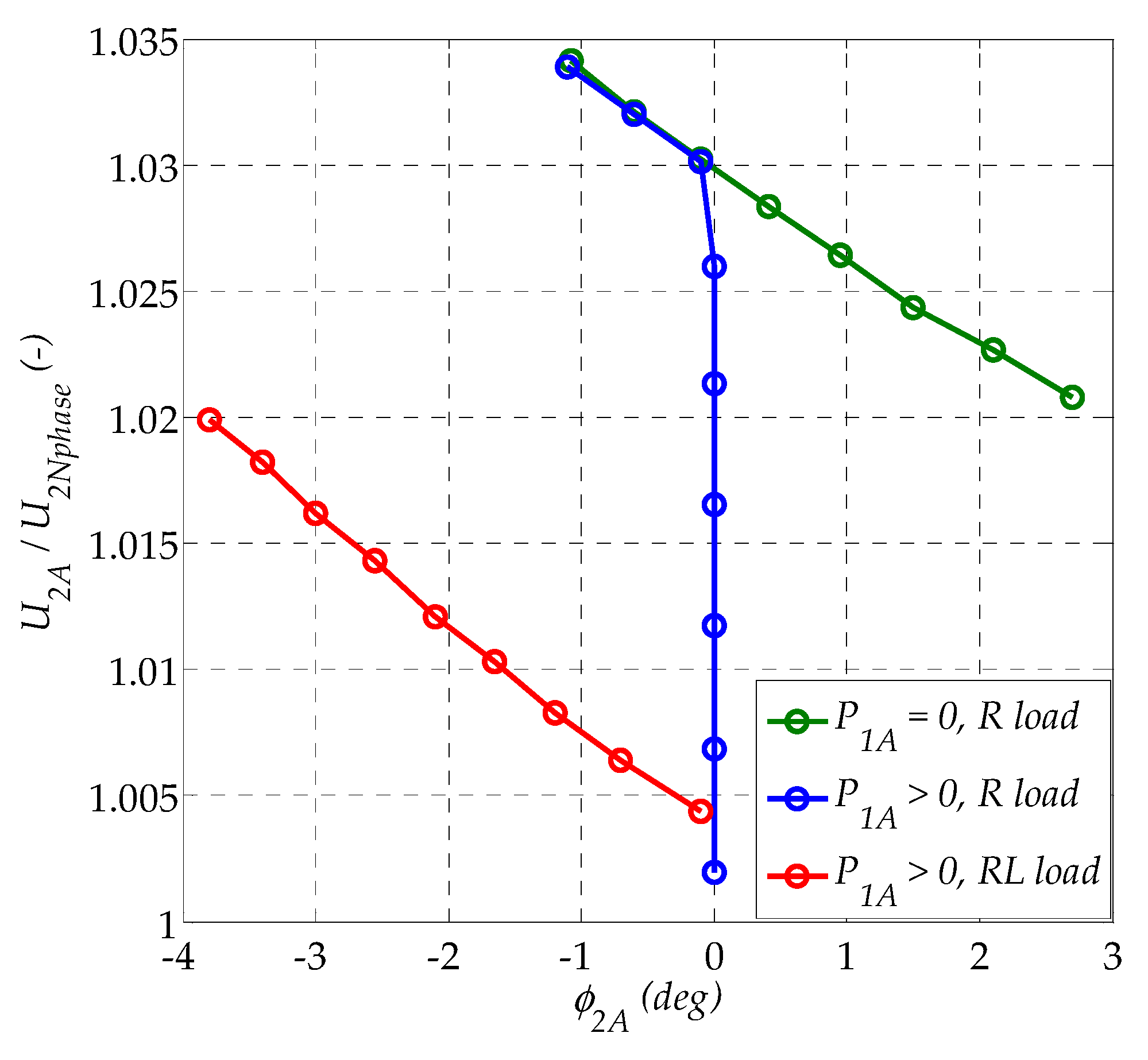
The Yy0 transformer consumes the same active power in all three phases of the MV side. This means that the voltage source connected to phase A of the LV side consumes active power. After changing RMS value and phase angle of the voltage of this source to U2A = 1.2·U2Nphase, φ2A = –20°, the transformer works in such a way that the power is delivered to phase A of the LV side and taken by receivers connected to the other two phases. However, this causes a significant level of phase voltage asymmetry. The transformer phase voltages are, successively, for phases A, B, C: 105%, 73%, 129% UNphase. This results in a significant difference between the power on phase B (12%) and phase C (51%) receivers, despite their identical impedances.
3.
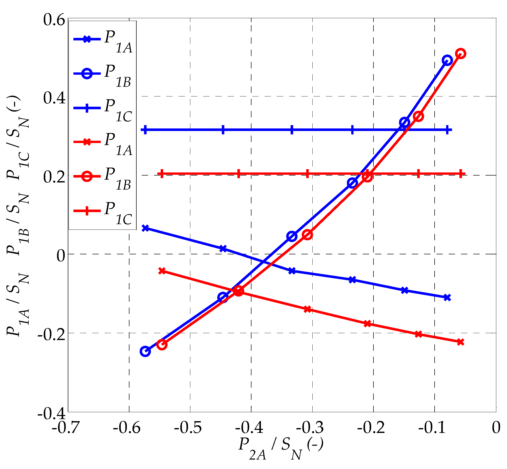
In a Dy0 transformer, most of the power supplied by the voltage source in phase A of the LV side is consumed by loads in the other two phases of that side. The power supplied to the MV grid in phase A is approximately zero (7%) and the effective active power consumption in both other phases (B, C) is reduced (24% and 20% instead of the expected 31% in each phase). This is due to the zero-sequence current in the delta-connected windings on the MV side. This zero component transfers the active power from phase A to phases B and C, and then this power is transformed back to the corresponding phases of the LV side. The total active power drawn from the MV side of the transformer is exactly the same as in the Y0y0 (32%), but the power of the individual phases is lower.
4.
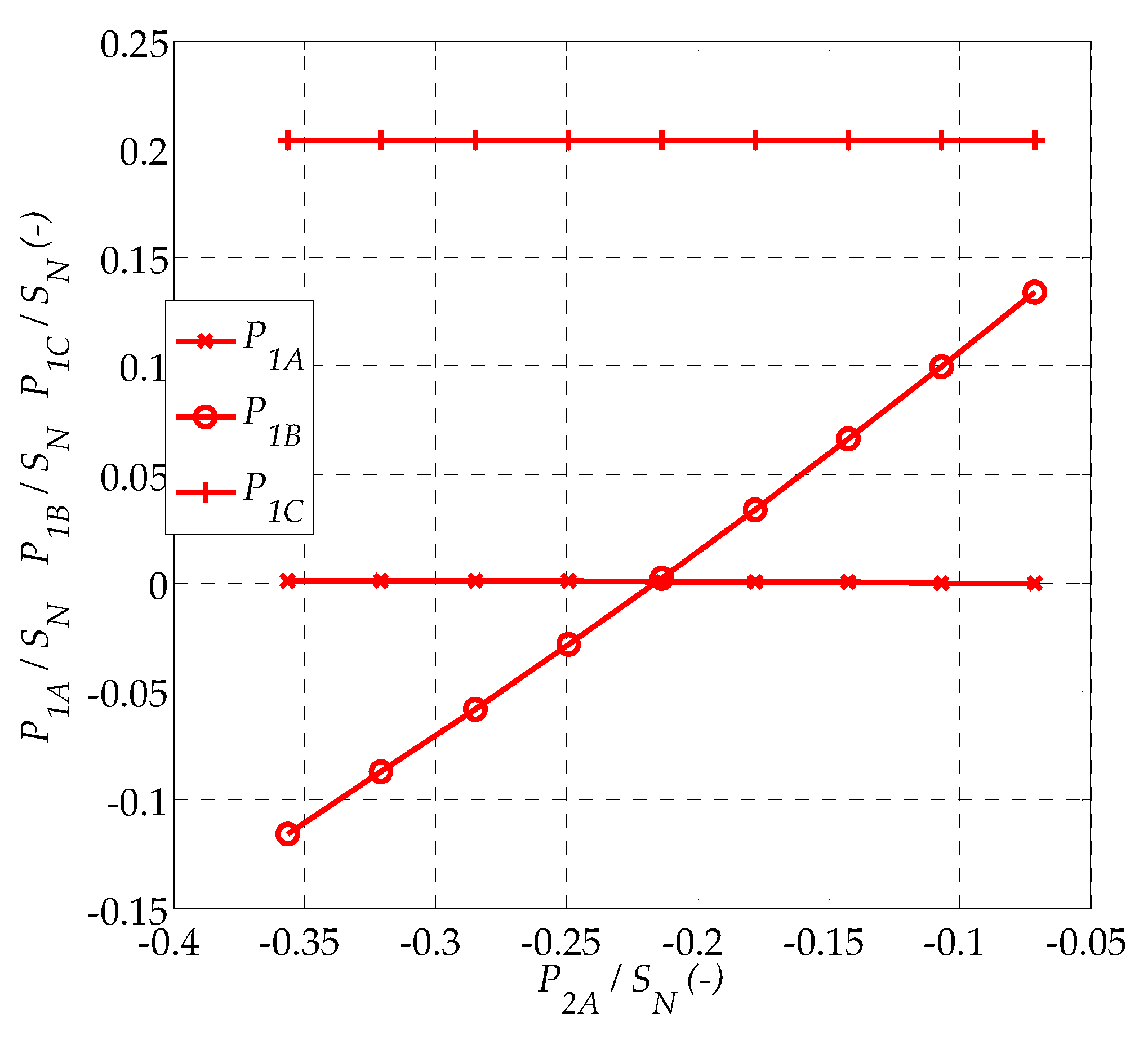
The calculation results obtained for transformers Y0z0, Yz0, Dz0 are identical. Most of the power supplied to phase A of the LV side goes to loads in the phases B, C of the LV side. The 4% active power is supplied to the MV grid (in the phase A of the MV side). The power consumption in phase B is 2% only. This is due to the appearance of the zero-sequence components of the currents on the LV side. It transfers power from the supplied phase A of the LV side to the phases B, C (mainly to phase B). The zero-sequence components of currents do not appear on the MV side of transformers Y0z0 and Dz0. The transformer phase voltages are symmetrical, same as voltages line-to-line. Power losses are the same as in other connections, in spite of the increased (by 15.5%) resistance of LV side phase windings, due to a higher number of turns of the zig–zag winding.
5.
In an ideal three-phase and three-column transformer, the zero-sequence currents do not appear on the primary side of the transformers at all [19]. In the ideal transformer equivalent circuit for the zero-sequence component, it is closed by the transverse branch of this circuit, because the impedance of this branch is zero (Lμ0 = 0 → Xμ0 = 0). Therefore, the obtained results are identical for various arrangements of the primary winding—the arrangement does not matter, because the zero-sequence currents do not appear on the transformer primary side. However, in a real three-column transformer, Lμ0 is very small (typically about 5% Lμ), but not zero, and this situation allows the appearance of the zero component currents on the transformer primary side.
It can be assumed that the active power from the supplied phase of LV is transported to the loaded phases by the zero-sequence currents. However, with the Y0y0 connection, this component can get out to the power source, and therefore the power is released to the MV grid. With the Yy0 connection, the power is transported between the phases of the LV side causing the asymmetry of phase voltages. When transformer Dy0 is used, the current’s zero components are on both sides of the transformer, while the transport of active power is provided by the current’s zero components in the delta-connected windings on the MV side. When connections Y0z0, Yz0, Dz0 are used, the current’s zero components are on the LV side only, which means that the method of windings connection on the MV side is not important for the power transmission process. These conclusions coincide with those obtained in [19]. Yz0 and Dz0 connections should be considered to be the best of the analyzed connections. They ensure the transport of the largest part of the active power from the supplied phase of the LV side to the loads connected to the phases B, C of the LV side. These connections maintain the symmetry of transformer phase voltages better than Dy0 and much better than Yy0.

3.2. Control of Power in the Transformer

On the basis of the results obtained, the Yz0 transformer was adopted for further simulations. The control quantities were RMS value and phase angle of the sine wave voltage supplying the phase A of the LV side. The controlled values were active power P2A supplied to phase A of the LV side (the control system is to maintain constant value of this power) and active power P1A of phase A of the MV side (the control system has to maintain a non-negative value of this power, i.e., prevent return of the active power to the MV grid in this phase).
The variability of both these powers as a function of the RMS value of the sine wave voltage supplying phase A of the LV side is shown in Figure 1. It shows that the control process of these powers is practically linear. Phase control of both powers is approximately linear (Figure 2). Similarly, the dependence of the phase’s power of the transformer’s primary side on the power delivered by a prosumer source is linear (Figure 3) or can be considered linear (Figure 4). For these reasons, it was decided to use a control system based on two PI controllers. The first adjusts P2A active power by controlling the RMS value of the voltage U2A, the second adjusts P1A active power by controlling the phase angle of that voltage (Figure 5).
Figure 6 and Figure 7 show examples of the dynamic waveforms of the P1A and P2A power control process obtained for the P2A power regulator settings: gain Kr = 0.0012 Vmax/W, integral time Ti = 75 ms, and P1A power regulator: Kr = 0.001 deg/W, Ti = 75 ms. The time charts in Figure 6 show the response of the system under test to the step change of the reference active power P2A = 0.3SN at time t = 0 and step change of the reference active power P1A = 0 at time t = 1 s. The process of simultaneous adjustment of both powers (at t = 0) is shown in Figure 7. Both figures show an undesirable interaction between the regulated active powers, but under the operating conditions of the transformer it can be considered as acceptable, due to the thermal acceptability of the power variations and their acceptable duration.
Figure 8 shows the static relationship between the RMS value of U2A and its phase angle φ2A resulting from the control system used. It is visible that the control system controls along straight lines, with changes resulting from the nature of the loads (R or RL) and due to the permission for active power consumption by phase A of the MV side (P1A > 0). A very small change is noticeable in the value and phase angle of the control voltage U2A. In practice, this may result in the necessity of attaching an additional choke in series to phase A of the LV side, allowing the use of higher values of amplitude and phase angle control signals, which would be easier to implement in practice.
The control effects in the control system from Figure 5, in static terms, are presented in Figure 9 and Figure 10 for the resistive load of two phases of the transformer secondary side and for the resistive–inductive load (p.f. = 0.8) of these phases. The analysis of Figure 9 and Figure 10 shows that the operation of the control system in Figure 5 cannot be considered as fully satisfactory. The problem is the active power of phase B of the primary side of the transformer. This can be seen especially in Figure 10, this power can be negative, i.e., returned to the MV grid. This is due to the fact that this power is not controlled. By the amplitude and phase of the sinusoidal voltage of the prosumer source, only the active power of the A phases of both sides of the transformer is controlled. The active powers of B and C phases are not controlled, just as the reactive powers of all phases of both sides of the transformer. Perhaps it is not possible to control these powers using only two control variables (the amplitude and the phase of the prosumer voltage). As can be seen in both figures, the control system works correctly in the sense of the control requirement P1A ≥ 0. The primary C phase active power is always constant and proportional to the secondary C phase active power.

3.3. Energy Losses in the Transformer

Figure 11 shows the power losses in the transformer windings for amplitude power control (as in Figure 1 and Figure 3). With an increase in the active power output by the prosumer source (for U2A > 0.994·U2Nphase) or consumed by it (for U2A < 0.994·U2Nphase), the power losses increase as a function of the square of the RMS value of the prosumer voltage source current. The minimum power losses occur when the prosumer source does not deliver and consume active power, i.e., when the voltage U2A = 0.994·U2Nphase (in Figure 11, it is U2A = U2Nphase).
Figure 12 shows the power losses in the transformer windings for phase power control (as in Figure 2 and Figure 4). With an increase in the value of the voltage’s phase angle of the prosumer source, the power losses increase rapidly, changing as a function of the square of the RMS value of the current output by the prosumer source. This control comes in addition to the active power and reactive power given (for φ2A > 0) or consumed (for φ2A < 0) by the prosumer source. It causes a general increase in load power losses compared to the amplitude control. For example, as shown in Figure 1 and Figure 2, the active power of 0.5SN given by a prosumer source can be obtained at U2A = 1.055·U2Nphase and φ2A = 0° or at U2A = 1.037·U2Nphase and φ2A = −5°. The transformer load losses in these two controls amount to, respectively, approx. 5%SN (acc. to Figure 11) and approx. 8.5%SN (acc. to Figure 12). It follows that the amplitude control of the active power of the prosumer source results in lower transformer power losses. This thesis is confirmed by the curves in Figure 13. Figure 13 shows the transformer’s load losses at amplitude (φ2A = 0°) and phase (U2A = 1.037·U2Nphase) control of the active power of the prosumer source, as a function of the active power output by this source, for other loads secondary side of R (p.f. = 1) or RL (p.f. = 0.8) types. There is a significant difference in these losses in favor of the amplitude control.
The control system from Figure 5 implements mixed, amplitude–phase control. The transformer’s load power losses with such control are shown in Figure 14. Unlike in the case of amplitude or phase control, these losses strongly depend on the nature of loads in two phases (B, C) of the transformer secondary side. Generally, these losses are higher than with amplitude control and lower than with phase control. For example, with amplitude control for P2A/SN = −0.3, transformer load power losses are 0.034SN at R load and 0.034SN at RL load. With phase control, these values are 0.042SN and 0.032SN, respectively. However, with amplitude–phase control, they are 0.034SN and 0.047SN. For P2A/SN = −0.2 transformer load power losses are 0.030SN at R load and 0.027SN at RL load. With phase control, they are 0.068SN and 0.052SN, respectively. However, with amplitude–phase control, they are 0.030SN and 0.032SN, respectively.

4. Discussion

The first part of the paper shows the outcome of simulation tests of the effect of the connection of three-phase windings of a distribution transformer on the flow of power between its phases in the case of voltage supply of one phase of the LV side and the MV side supplied with the rated voltage. Similarly to the three-phase low-power transformer analyzed in [19], the result was obtained that the active power is transferred between the transformer’s phases by the zero-current component of the LV side and the MV side. The zig–zag connection was considered to be the best connection of the LV side windings due to the occurring limitation of the active power given to the mains supplying the MV side of the transformer and maintaining almost constant RMS values of the transformer’s voltages. For this connection of LV side windings, the active power is transferred from the supplied phase of the LV side through the zero-current component to the loaded phases of the LV side. In such a case, the connection of windings on the MV side is not important because the zero components are not transferred to the MV side. For these reasons, further investigations were carried out for the transformer Yz0.
The main objective of the further investigations was to make a control system to minimize the power delivered to the MV grid. While constructing the control system, the focus was on minimizing the power output to the grid through this phase of the MV side of the transformer, which corresponds to the supplied phase of the LV side. Such an approach was adopted on the basis of preliminary calculations, which showed that if the active power is released to the grid through the MV side of the Yz0 transformer, its majority part flows through the phase that is supplied from the LV side. A linear control system with the expected properties was developed and subjected to simulation tests. They showed its correct operation, both in static and dynamic mode. The control system minimized the active power supplied to the network through phase A of the MV side, thus minimizing transformer power losses and transmission losses on the MV side. Unfortunately, this control process does not apply to the active powers of the B, C phases of the primary side. They are not controlled, and the active power of the B phase may be negative, i.e., it may be delivered to the MV grid.

5. Conclusions

The current form of the developed control system is not fully satisfactory compared to the control of phase voltages of the transformer/grid, used in many other solutions [1,2,3]. The problem is to control the powers of other phases of the transformer, as well as the phase reactive powers. Further research should be focused on the development of a control system that also controls the active power supplied to the MV grid through other phases of the transformer. This system must use different control trajectories than those shown in Figure 8. Note that no other trajectories were tested. On the basis of the conducted research, it is impossible to answer which active and reactive powers of the transformer phases correspond to the points of the plane that are outside the drawn trajectories. This requires further research. It is possible that the use of these points will also allow the reactive power of the transformer phases to be controlled. Here, however, there is a fundamental problem: how many transformers’ phase powers can be controlled simultaneously with only two control variables (the amplitude and the phase of the prosumer source’s voltage). It is possible that the scope of the control possibilities is limited. In such a situation, it would be necessary to control the powers also by means of other single-phase RESs connected to other phases of the distribution network (LV side of the transformer).
The further direction of research is to control multiple voltage sources, connected to different phases of the LV side of the distribution transformer, owned by different prosumers. This control would also have to take into account the results presented in the paper [14]. The purpose of the control would then also be to limit or eliminate the release of active power to the MV network by the distribution transformer. The energy produced by individual prosumers should be consumed first by themselves and additionally by other consumers connected to the same LV grid but should not be transferred to the MV grid.

Author Contributions

Conceptualization, T.D. and P.D.; methodology, T.D.; software, P.D.; validation, T.D. and P.D.; investigation, T.D.; writing—original draft preparation, T.D.; writing—review and editing, P.D. Both authors have read and agreed to the published version of the manuscript.

Funding

This research was funded by in the framework of project “The development of dispersed generation in energy clusters” funded by the Polish National Center of Research and Development, grant number Gospostrateg1/385085/21/NCBR/2019.

Institutional Review Board Statement

Not applicable.

Informed Consent Statement

Not applicable.

Data Availability Statement

The data presented in this study are available on request from the corresponding author. The data are not publicly available because they belong to results an project in progress (Gospostrateg1/385085/21/NCBR/2019).

Conflicts of Interest

The authors declare no conflict of interest. The funders had no role in the design of the study; in the collection, analyses, or interpretation of data; in the writing of the manuscript; or in the decision to publish the results.

References

  1. Patel, D.; Chowdury, A. Dynamic Control and Performance of a Sen Transformer for Stabilizing an AC TransmissionSystem and Improved Voltage Profile. In Proceedings of the International Conference on Power, Energy, Control and Transmission Systems (ICPECTS), Chennai, India, 22–23 February 2018; pp. 85–90. [Google Scholar]
  2. Foti, S.; De Caro, S.; Testa, A.; Tornello, L.D.; Scelba, G.; Cacciato, M. An Open-End Winding Hybrid Transformer. In Proceedings of the International Symposium on Power Electronics, Electrical Drives, Automation and Motion, Sorrento, Italy, 24–26 June 2020; pp. 173–177. [Google Scholar]
  3. Gong, X.; Hua, Y.; Xie, J.; Tang, L.; Li, X. Study on Voltage and Reactive Power Control of 10kV Direct Load Supply of 220 kV Transformer Substation. In Proceedings of the IEEE PES Innovative Smart Grid Technologies Asia, Chengdu, China, 21–24 May 2019; pp. 1096–1101. [Google Scholar]
  4. Faiz, J.; Ebrahimi, B.M.; Ghofrani, M. Mixed Derating of Distribution Transformers Under Unbalanced Supply Voltage and Nonlinear Load Conditions Using TSFEM. IEEE Trans. Power Deliv. 2010, 25, 780–789. [Google Scholar] [CrossRef]
  5. Kelley, A.W.; Edwards, S.W.; Rhode, J.P.; Baran, M.E. Transformer derating for harmonic currents: A wide-band measurement approach for energized transformers. IEEE Trans. Ind. Appl. 1999, 35, 1450–1457. [Google Scholar] [CrossRef]
  6. Masoum, M.A.S.; Moses, P.S.; Masoum, A.S. Derating of asymmetric three-phase transformers serving unbalanced nonlinear loads. Trans. Power Deliv. 2008, 23, 2033–2041. [Google Scholar] [CrossRef] [Green Version]
  7. Aboura, F.; Touhami, S.A.; Zama, A.I.; Tahmi, R.; Touhami, O.; Boughrara, K. Dynamical Modeling and Analysis of Asymmetric Unbalanced Three-Phase Transformers. In Proceedings of the 2015 Intl. Aegean Conference on Electrical Machines & Power Electronics (ACEMP), 2015 Intl. Conference on Optimization of Electrical & Electronic Equipment (OPTIM) & 2015 Intl. Symposium on Advanced Electromechanical Motion Systems (ELECTROMOTION), Side, Turkey, 2–4 September 2015; pp. 623–629. [Google Scholar]
  8. Zecchino, A.; Marinelli, M.; Hu, J.; Coppo, M.; Turri, R. Voltage Control for Unbalanced Low Voltage Grids Using a Decoupled-Phase On-Load Tap-Changer Transformer and Photovoltaic Inverters. In Proceedings of the 50th International Universities Power Engineering Conference (UPEC), Stoke on Trent, UK, 1–4 September 2015; pp. 1–6. [Google Scholar]
  9. Razmkhah, M.; Azizian, M.R.; Kojabadi, H.M. Photovoltaic systems based on power electronic transformer with maximum power tracking capability. In Proceedings of the 22nd Electrical Power Distribution Conference, Semnan, Iran, 19–20 April 2017; pp. 74–79. [Google Scholar]
  10. Chattopadhyay, R.; Bhattacharya, S. Modular Isolated DC-DC Converter with Multi-Limb Transformer for Interfacing of Renewable Energy Sources. In Proceedings of the IEEE Applied Power Electronics Conference and Exposition (APEC), Charlotte, NC, USA, 15–19 March 2015; pp. 3039–3046. [Google Scholar]
  11. Hazra, S.; Bhattacharya, S.; Chakraborty, C. A Novel Control Principle for a High Frequency Transformer Based Multiport Converter for Integration of Renewable Energy Sources. In Proceedings of the IECON 2013—39th Annual Conference of the IEEE Industrial Electronics Society, Vienna, Austria, 10–13 November 2013; pp. 7984–7989. [Google Scholar]
  12. Ouyang, S.; Liu, J.; Wang, X.; Song, S.; Hou, X. Comparison of Four Power Electronic Transformer Topologies on Unbalanced Load Correction Capacity. In Proceedings of the IEEE Energy Conversion Congress and Exposition (ECCE), Montreal, QC, Canada, 20–24 September 2015; pp. 3702–3709. [Google Scholar]
  13. Athul, M.V.; Preetha, P.K.; Nair, P.S.C. Analysis of Star-Star Delta Utilized Transformer under Balanced and Unbalanced Load Conditions. In Proceedings of the IEEE Industry Applications Society Annual Meeting, Addison, TX, USA, 18–22 October 2015; pp. 1–6. [Google Scholar]
  14. Zou, Z.X.; Buticchi, G.; Liserre, M. Analysis and Stabilization of a Smart Transformer-Fed Grid. IEEE Trans. Ind. Electron. 2017, 65, 1325–1335. [Google Scholar] [CrossRef]
  15. Bottrell, N.; Prodanovic, M.; Green, T.C. Dynamic stability of a microgrid with an active load. IEEE Trans. Power Electron. 2013, 28, 5107–5119. [Google Scholar] [CrossRef] [Green Version]
  16. Rockhill, A.A.; Liserre, M.; Teodorescu, R.; Rodriguez, P. Grid-filter design for a multimegawatt medium-voltage voltage-source inverter. IEEE Trans. Ind. Electron. 2011, 58, 1205–1217. [Google Scholar] [CrossRef] [Green Version]
  17. Jauch, E.T. Maximizing automatic reverse power operations with LTC transformers and regulators. In Proceedings of the IEEE Power Engineering Society Inaugural Conference and Exposition in Africa, Durban, South Africa, 11–15 July 2005; pp. 449–454. [Google Scholar]
  18. Al-Riyami, A.; Burt, K.; Manhangwe, G.; Pretlove, P.; Georgiopoulos, S. An Investigation into Alternatives to Directional Overcurrent Protection on Grid Transformers to Improve the Network Capacity to Accommodate Reverse Power Flow. In Proceedings of the 12th IET International Conference on Developments in Power System Protection, Copenhagen, Denmark, 31 March–3 April 2014; pp. 1–6. [Google Scholar]
  19. Drabek, T.; Dybowski, P. Control of prosumer energy sources in power grid feeded by three-phase distribution transformer. In Proceedings of the 15th Selected Problems of Electrical Engineering and Electronics (WZEE), Zakopane, Poland, 8–10 December 2019. [Google Scholar]
  20. Drabek, T.; Dybowski, P. Control of prosumer voltage sources in distribution grids. In Proceedings of the 12th International Conference and Exhibition on Electrical Power Quality and Utilisation (EPQU), Kraków, Poland, 14–15 September 2020. [Google Scholar]
  21. Zhang, C.; Li, Y.; Li, J.; Yang, Q.; Zhu, J. Measurement of Three-Dimensional Magnetic Properties with Feedback Control and Harmonic Compensation. IEEE Trans. Ind. Electron. 2017, 64, 2476–2485. [Google Scholar] [CrossRef]
  22. Tang, Q.; Wang, Z.; Anderson, P.I.; Jarman, P.; Moses, A.J. Approximation and Prediction of AC Magnetization Curves for Power Transformer Core Analysis. IEEE Trans. Magn. 2015, 51, 1–8. [Google Scholar] [CrossRef]
Figure 1. Amplitude control of active power P1A and P2A at φ2A = 0 (blue line—R load, red line—RL load, p.f. = 0.8).
Energies 14 01038 g001
Figure 2. Phase control of active power P1A and P2A at U2A = 1.037·U2Nphase (blue line—R load, red line—RL load, p.f. = 0.8).
Energies 14 01038 g002
Figure 3. Active powers of the phases of the transformer’s primary side at the R or RL load of the secondary side B and C phases, as a function of the active power of the prosumer source in phase A of the secondary side, with amplitude control (blue line—R load, red line—RL load, p.f. = 0.8).
Energies 14 01038 g003
Figure 4. Active powers of the transformer’s primary phases with R or RL load of B and C phases (as in Figure 3), with phase control.
Energies 14 01038 g004
Figure 5. Diagram of control system P1A and P2A of Yz0 transformer.
Energies 14 01038 g005
Figure 6. Waveforms of active powers P1A and P2A for RL load, p.f. = 0.8.
Energies 14 01038 g006
Figure 7. Waveforms of active powers P1A and P2A for RL load, p.f. = 0.8.
Energies 14 01038 g007
Figure 8. Relationship between the RMS value of U2A and its phase angle φ2A of the control system.
Energies 14 01038 g008
Figure 9. Active powers of the phases of the primary side of the transformer at the load R of phases B and C of the secondary side, as a function of the active power of the prosumer source in phase A of the secondary side, with amplitude–phase control.
Energies 14 01038 g009
Figure 10. Active powers of the phases of the primary side of the transformer at the load RL (p.f. = 0.8) of phases B and C of the secondary side, as a function of the active power of the prosumer source in phase A of the secondary side, with amplitude–phase control.
Energies 14 01038 g010
Figure 11. Load losses of the transformer with amplitude control as a function of this amplitude value, at φ2A = 0.
Energies 14 01038 g011
Figure 12. Load losses of the transformer with phase control as a function of the angular value of this phase, at U2A = 1.037·U2Nphase.
Energies 14 01038 g012
Figure 13. Load losses of the transformer with amplitude or phase control as a function of the active power value of the prosumer source.
Energies 14 01038 g013
Figure 14. Load losses of the transformer with amplitude–phase control of active powers P2A, P1A.
Energies 14 01038 g014
Table 1. Calculation results for MV/LV transformer. In brackets, the results of phase active power calculations for the delta connection that are exchanged with the grid—without the zero component of phase currents.
Winding AssociationI20/I2NP2A/SNP2B/SNP2C/SNP2/SNI10/I1NP1A/SNP1B/SNP1C/SNP1/SNΔPCu/SN
Y0y00.60−0.280.300.300.320.60−0.270.320.320.370.05
Yy00.060.280.280.280.8400.270.320.290.880.04
Yy0, U2A =
1.2·U2Nphase
φ2A = –20°
0.30−0.120.120.510.5100.050.170.330.550.04
Dy00.60−0.280.300.300.320.60−0.27 (−0.07)0.32 (0.24)0.32 (0.20)0.37 (0.37)0.05
Y0z00.68−0.350.300.300.250−0.040.020.320.300.05
Yz00.68−0.350.300.300.250−0.040.020.320.300.05
Dz00.68−0.350.300.300.250−0.04 (−0.04)0.02(0.02)0.32 (0.32)0.30 (0.30)0.05
Publisher’s Note: MDPI stays neutral with regard to jurisdictional claims in published maps and institutional affiliations.

