Review

The Silent Path: The Development of the Single Sleeve Valve Two-Stroke Engine over the Last 110 Years

Mechanical Engineering, Faculty of Engineering and Design, University of Bath, Bath BA2 7AY, UK
*
Author to whom correspondence should be addressed.
Energies 2021, 14(3), 616; https://doi.org/10.3390/en14030616
Submission received: 17 September 2020 / Revised: 20 November 2020 / Accepted: 23 November 2020 / Published: 26 January 2021
(This article belongs to the Special Issue Alternative Engines and Alternative Fuels)

Abstract

:
At the beginning of the 20th century the operational issues of the Otto engine had not been fully resolved. The work presented here seeks to chronicle the development of one of the alternative design pathways, namely the replacement for the gas exchange mechanism of the more conventional poppet valve arrangement with that of a sleeve valve. There have been several successful engines built with these devices, which have a number of attractive features superior to poppet valves. This review moves from the initial work of Charles Knight, Peter Burt, and James McCollum, in the first decade of the 20th century, through the work of others to develop a two-stroke version of the sleeve-valve engine, which climaxed in the construction of one of the most powerful piston aeroengines ever built, the Rolls-Royce Crecy. After that period of high activity in the 1940s, there have been limited further developments. The patent efforts changed over time from design of two-stroke sleeve-drive mechanisms through to cylinder head cooling and improvements in the control of the thermal expansion of the relative components to improve durability. These documents provide a foundation for a design of an internal combustion engine with potentially high thermal efficiency.

1. Introduction

If the internal combustion engine is to play any part in combating the environmental pressures on personal mobility in the third decade of the 21st Century it will require that automotive engineers review all technologies likely to produce low-cost engines which do minimum harm to the environment. One way forward in this was suggested by Gaplin et al. [1] with their work in two-stroke diesel engines with forward and reverse uniflow scavenging air flows. However, their results were greatly affected by the gas exchange limits imposed by the use of poppet valves in their designs. Fortunately, there is another way to address the problem of the valve heads at low valve lifts interfering with the in-cylinder air motion.
Poppet valves have been the default technology for gas exchange in internal combustion engines for the last 110 years. However, there were many other technologies tried in the past. Sometimes a re-evaluation of these systems can help resolve long-standing problems.
This can help in keeping the IC engine competitive as an option for an effective means of powering cars in a CO2 constrained world. One such technology worth considering is the sleeve-valve in either a 4-stroke or two-stroke configuration.
The sleeve valve is a thin-walled cylinder located between the piston and the engine cylinder liner. This cylinder is designed to move relative to both the liner and piston so that a number of slots cut into it at appropriate points can be aligned with the gas passages of the engine at a suitable interval in the engine cycle allowing gas exchange to take place.
There are a number of sound engineering reasons why the sleeve valve is superior to the poppet valve arrangement in engines. These include:
  • Larger valve flow areas for the same bore and stroke than a poppet valve engine [2].
  • There is no valve, valve stem, or valve guide to affect air flow at small port openings.
  • Higher effective compression/expansion ratios than that of poppet valve engines are possible at the same knock limit for a common fuel quality (RON or MON) [2].
  • Complete flexibility in the design of combustion chamber shape, injector, or spark plug position, as there are no valve discs to consider.
  • Removal of many of the hot spots in the cylinder head i.e., components such as the exhaust valves.
  • Desmodromic valve operation is simple to achieve (and indeed the norm), leading to reduced limitations on gas exchange and engine speed.
  • Reduction in number of engine parts, including the elimination of valves, valve spring, followers, and associated paraphernalia.
  • Quieter operation.
  • Reduced engine height for a given engine stroke length (as there is no valve train mechanism above the cylinder head to consider).
  • Potentially better heat transfer behaviuor.
  • Simple cylinder disablement, depending on the valve drive mechanism.
  • Reduced component wear.
  • Potentially lower running friction.
  • The possibility of supercharging and/or Atkinson cycle operation on a two-stroke engine.
For this technology, it is possible to use a patent history to show how it developed over time until the “commercial” will to move forward stopped. The reason why the concept was not commercialised more, is a subject in itself. However, in summary, during the war years, the engine manufacturers and the oil industry developed an understanding on how to solve a number of the major poppet valve engine problems. These included optimising of cam profiles, the use of sodium-cooled exhaust valves, and understanding of fuel knock behaviours to improve engine knock limits. These were partly achieved with the introduction of leaded gasoline blends which allowed higher compression/expansion ratios to be used in the engines for the same boost level and hence lower exhaust gas temperatures. This reduced the likelihood of exhaust valve failures and preignition at the same time. Hence, after the war, it was cheaper for the automotive manufacturers of engines to develop what they already knew, than to build new engine plant for a design concept known to only a few.
In addition, in the pre-war period, the aero engine manufacturers had pioneered technologies which then disseminated to the auto industry. However, with their change in direction into gas turbines post-war, this link was broken. due to the fact that gas turbines have operating characteristics that are generally unsuited to automotive applications. No new automotive sleeve valve engines were produced after the war and the technology has been partly forgotten.

2. Birth of Sleeve Valve Technology: The First Decade of 20th Century

It was Charles Yate Knight who first suggested a possible alternative gas exchange process control system for the four-stroke engine. Which up to that time had either used steam-engine-like slide valves or the poppet valves that are ubiquitous today.
The first of these was his vertical moving sleeve arrangement shown (Figure 1) as per patent US968166 of April 1904 [3]. He further improved his ideas in his patent US1090991 of 4 June 1906 [4] (Figure 2) proposing that the poppet valves be replaced by a pair of thin sliding liners which surrounded the piston, these nested inside each other and were driven up and down by separate cranks at half engine speed.
These sleeves having slots in them which allow for gas exchange to take place at suitable times in the Otto cycle. Determined by the operation of the sleeve crank drive mechanism. This coordinated both the opening and closing of the ports making it much quieter in operation compared with the cam operated poppet valve engines of the era. Furthermore, without hot exhaust valves, the knock performance of the engine was superior to that of the poppet valve engine when run on the same lower octane fuels as well.
However, this new invention was not without its own set of shortcomings, which included problems with cylinder (or “junk”) head cooling, liner sleeve seizure, and high oil consumption. This final item was even highlighted by the inventor himself, in his later patent of November 1908 [5], in which he conceded that there was an issue with the lubrication of the two nested sleeves and that the lubricant tended to escape into the combustion space or into the exhaust system where it produced oil smoke.
Notwithstanding this, several automakers of the period did take up the idea for production, two of note being the Willy’s Car Company in the US and Daimler of Coventry in England [6]. Engines of this type were produced into the early 1930s. However, it was the in following year, 1909 that two independent designers disclosed similar ideas that addressed the shortcomings of the Knight double-sleeve arrangement within three months of each other.
These were Peter Burt, [6] a Scottish inventor, and James McCollum, [7] from Canada. They independently invented the mono- or single-sleeve valve mechanism, which as a result of the combination of their individual design characteristics came to become known as the Burt–McCollum sleeve valve. (Figure 3 and Figure 4) show their original patents.
The major step forward in this device was the motion of the single sleeve. Knight’s twin moving sleeves operated in a pure vertical motion at half engine speed in the case of 4-stroke operation. The Burt–McCollum single sleeve arrangement manages to achieve this by a combination of vertical and rotational movement of the sleeve. This can be achieved by a crank, fitted with a peg which slides in and out of a drive ball in a socket attached to the sleeve. While knight design the exhaust port activate only when slots in both of the inlet and exhaust sleeves were lined up with the necessary external port in the cylinder wall, the Burt–McCollum single sleeve with correctly positioned and profiled slots can, if its motion is suitable, be used to control both the inlet and exhaust events. This arrangement can be considered to have the same degrees of freedom as a single overhead camshaft arrangement in a conventional engine. In the single sleeve four-stroke the drive apparatus operates at half crankshaft speed in a manner similar to a camshaft drive in a poppet valve engine. However, for two-stroke engine applications the mechanism needs to operate at crankshaft speed.
The application was first used in the Argyll motor vehicle of 1911.
Unfortunately, the Argyll motor company went bankrupt in 1914 (caused in part by a lawsuit related to the sleeve valve engine technology) [8]. The rights to the sleeve valve engine were then bought by Continental Motors of England (part of the greater Continental group) in 1926, after which the major site of patent activity moved across to Detroit in the USA. After this, there was a great deal of patent activity as the 4-stroke engine was developed. but that is another story.
The first of the two-stroke sleeve-valve engine patents actually appeared in 1915.

2.1. History of the Two-Stroke Engine Sleeve Valve Arrangement

2.1.1. Early Developments

The idea that a sleeve valve could be applied to the two-stroke engine architecture came early. It allows the symmetric gas exchange timing of a simple piston-ported two-stroke engine to be modified allowing an extra degree of freedom, enabling asymmetric timing. By this means the amount of time the exhaust port is open after the inlet port has shut is reduced which moderates the fresh charge short-circuiting at the end of the exhaust gas scavenging event. In the extreme case, the inlet port could even be closed before the exhaust port. This allows for either, expelling unrequired air at light load or allowing extra air to be forced in under pressure when necessary at high load.
In Hunt’s invention of 1915 [9] (Figure 5), the first concept, the sleeve motion was controlled by a cam on the crank and a large return spring mounted in the junk head. In all probability, this latter component would have been extremely unhelpful for cooling the head, but the engine used a wet sump, unlike the crankcase scavenged 2 stroke engines of the period.
In his patent of 1916 [10] (Figure 6) Stokes moved the spring from the junk head to the area above the crankcase. In this case, the sleeve was driven either by a cam-lobe or an eccentric circle drive on the crankshaft. In his concept, the bottom of the sleeve also functions as an annular piston in a scavenge pump unit. This allowed the wet sump arrangement to be maintained for piston lubrication.

2.1.2. 1930s and the War Years

These ideas then lay dormant until the 1930s. The first of the true sleeve-valve two-strokes was patented by Bischof (Figure 7) in 1931 [11] for a low-speed diesel engine application. The drive followed a quite different concept. The mechanism was complex with the drive taken directly from the crank via a pin-and-slider arrangement (which in turn was likely to be speed limited) but the principles were determined with the asymmetric gas exchange events potential clearly disclosed. Additionally, the ports were arranged with the exhaust close to the head and the inlet at the crankshaft end, in a manner which could be considered to become the norm in later two-stroke sleeve-valve applications.
This was followed by Kipfer [12] (Figure 8) who simplified the concept and produced a design with an elliptical (Burt–McCollum-type) [6,7] drive mechanism for a smaller diesel engine. The asymmetric timing potential of a two-stroke in the design is clearly shown in the patent.
This was improved further by Kammer [13] who combined this with his work on drive mechanisms for 4-stroke sleeve valve engines and introduced a secondary set of “boost” ports part way up the sleeve. (Figure 9) These boost ports would only operate under specific high load conditions. Due to this fact, the cylinder volume above the piston rapidly reduces during the compression phase accordingly. Consequently, the later the inlet ports were left open, the higher the boost pressure would have had to be to overcome this pressure to increase the fresh charge mass. In turn, this would increase the work required of the inlet scavenge pump system to provide the extra pressure.
Scott’s design [14] Figure 10 was the first to locate the inlet ports near the junk head and the exhaust ports close to the crank shaft. He also introduced a variable-stroke sleeve drive to allow variation in gas exchange events. However, the sleeve motion does not rotate now.
By this point in time major engineering companies were beginning to take an interest in two-stroke sleeve-valve engines such as Rolls Royce.
The patent by Rowledge of Rolls-Royce of 1939 [15] (Figure 11) shows one route to provide a single central drive to operate two cylinders simultaneously in a V engine arrangement, significantly reducing complexity in the architecture.
This would be further refined from a separate drive shaft to a mechanism which ran directly off the crank with a lost motion slave piston arrangement as used in the later Rolls-Royce Crecy engine which also had a 90° V engine architecture (Figure 12).
In Britain, Harry Ricardo, who was ever a strong advocate of the sleeve-valve engine produced his own drive design [16] (Figure 13). He also built a number of single-cylinder research engines, which were used to support the efforts of Rolls-Royce [17] and D. Napier & Son, who produced their own twin-cylinder experimental engine, the E.113 [18].
The design shows the use of a slave joint and eccentric drive of the crankshaft that was successful in the Rolls-Royce Crecy engine. They also continued to place the inlet port at the bottom with the exhaust at the junk head end, which enabled increased blow down performance at the expense of ultimate efficiency, blow down being the period from when the exhaust port opens to the point at which the cylinder pressure reduces to that of the exhaust manifold.
The Rolls-Royce Crecy (Figure 14) can effectively be considered the swansong for the two-stroke sleeve-valve concept as it was the last to be built even in prototype numbers. This engine, a 24-litre V12, was built and the initial running was promising, as was documented by Nahum, et al. [18] and Hiett and Robson [17]. It was also tested in supercharged and turbo-compounded forms, the latter with an exhaust turbine geared into the supercharger drive. Originally it was intended for interceptor fighters, where extremely high power-to-weight ratios take priority over fuel consumption. However, its fuel consumption was actually good in compound form. Nevertheless, with the exigencies of war, and Rolls-Royce’s increasing involvement in gas turbine propulsion for aircraft, development was ultimately halted, and all of the test engines were destroyed in 1946 [18].
Towards the end of the war, other designs were patented. Halsing [19] (Figure 15) considered an arrangement where the sleeve was controlled by a pair of connecting rods driven off the crank. This returns the sleeve motion to a simpler reciprocating type. The phasing of the sleeve is still some degrees advanced of the crankshaft and the exhaust port remains at the head end. The novel feature was that the inlet ports were broken up into three sub-ports, which were opened and closed progressively by the piston motion during the compression phase.
This enabled different swirl levels to be imparted to the incoming charge through the ducts, as each set had a different inlet channel angle relative to the bore, thus helping to scavenge residual gas and to control rates of combustion.
There was also an embodiment of the patent with a secondary inlet port control sleeve (i.e., a cuff) outside of the liner to further control gas exchange timings.
The work by Meulien [20] (Figure 16) retains the original Burt–McCollum motion but allows for variable stroke length in the sleeve drive to further adjust gas exchange events. In this design, the effective time area is changed as well as the opening and closing of the ports.
Sparmann [21] proposed an alternative design (Figure 17) achieved by the introduction of an additional driven element which modified the input motion to the sleeve. This delivers more vertical movement to the sleeve when aligned with the ports for gas exchange (increasing the effective port open duration) but then generates increased radial velocity during the compression and expansion strokes when the piston is moving faster.
However, after World War 2 the aero engine two-stroke work rapidly tailed off, as the gas turbine engine took over the role for propulsion in aircraft. Nevertheless, while at Rolls-Royce Tresilian proposed a very highly compounded sleeve-valve engine developed from the Crecy arrangement. (Figure 18) It was an “X” configuration of four banks each at 90° to each other. Its sleeve drive was to have been an evolution of the Ricardo arrangement, with the two opposing sleeves in a crankcase bay. These were driven by a drive rod assembly off an eccentric cut into the crankshaft cheeks with the assembly having a swinging slave link grounded to the crankcase [17]. The other two cylinders in the bay at 90° to the first pair had a similar arrangement driven from the crankshaft cheek. Overall, this gave an extremely compact engine. His calculations suggested that his “X-engine” would have significantly better fuel consumption than contemporary gas turbines and would have been ideal for what would now be thought of as the small turboprop market. Ultimately, though, it came to naught, although it does still suggest a direction for highly compact engine architectures.
After that, patent activity slowed down until the turn of the 21st century.
The next design by Chen et al. [22] (Figure 19) suggests an arrangement in which the sleeve is forced down against a spring by the piston during the expansion stroke, which then causes the sleeve to open the gas exchange ports. The large diameter spring then returns the sleeve to its original position as the piston rises again. Unfortunately, there is no consideration for asymmetric gas exchange timing with this design.
In Beninca’s patent [23] (Figure 20) the drive train for the sleeve is modified, with the introduction of a pair of drives. This imparts a compound motion to the single sleeve which gives improved port opening and closing dynamics thus allowing asymmetric gas exchange timing to be achieved again with the engine.
The next arrangement by Cleeves [24] (Figure 21) allows the junk head internal surfaces to move relative to the piston, which changes the geometric compression and expansion ratios, while still allowing the sleeve movement to control the gas exchange in the ports via, a collar and lever drive device which produces a linear motion on the sleeve.
The design offered by Ellis [25] (Figure 22) is a complex design in which a pair of cylinders have opposed pistons in them. These act on a pair of double-sided cam rings located at either end of the engine which drives a central shaft. The gas exchange events are controlled by sleeves which are in turn driven off another pair of cam rings.
The Pattakos device [26] (Figure 23) uses a toothed gear built on the outer diameter of the liner to cause it to rotate at crank speed allowing the opening and closing of the engine ports, at the required timings. This however limits the size of the engine as the number of teeth on the crank driving gear must match those on the driven gear on the liner.
This is the last fully mechanical system found to date.
The work of Turner et al. of Lotus [27] (Figure 24) where the sleeve motion is controlled via a yoke plate in one embodiment and electronic controlled hydraulic actuators in another. This allows both directions of motion of the sleeve to be driven and controlled independently of the crankshaft motion, allowing all three degrees of freedom in gas exchange to be covered, port area, event timing, and duration. It is further possible to programme the motion to be adjustable for both speed and load when connected to an electrical variable-speed compression or scavenge pump. Thus, all forms of engine control would be possible, including full cylinder deactivation and skip-firing in any order and frequency as required.

2.1.3. Engine Design Issues

As with any engine design, there have been several areas of concern. These have included the following:
  • Seizure of the engine caused by thermal expansion of different components
  • Junk head cooling
  • Piston cooling
  • Sleeve roundness (a specific issue for sleeve valves)
The first of these was a specific issue with high-performance air-cooled engines, where the heat rejection requirement is high. This would also be the case in any two-stroke engine. It was found that specific locations on the sleeve were exposed to high temperatures for different durations this led to dissimilar localised increases in thermal expansion. It was resolved by careful tolerancing, flaring the external diameter of the sleeve by a small amount, and using sleeve materials which have similar expansion coefficients as other key components, namely the piston, junk head, and cylinder block [28].
Junk head cooling on a sleeve valve two-stroke engine is considered doubly challenging due to the increased frequency of the heat flux events and the more complex heat path. Much work was done on developing suitable strategies for temperature control during the 1930s, with a number of patents being written on how to achieve the required level of cooling. An example of this being the work by Mayer (Figure 25).
Mayer showed the need for extensive finning and deep air-cooled passages in his patent of 1935 [29] Figure 25 to remove the heat from the head area. In addition, it is interesting to note the number of bolts used to hold the junk head in place. It is suggested this helped with minimising distortion of the sleeve pocket under compression. helping to maintain operational clearance under load.
The extreme version of these ideas can be seen in the patent of Fedden of the Bristol Engine Company [30] (Figure 26) where the ducting around the junk head is extensive to ensure the directionality of the high flow rates of air (the cooling medium) required to reduce overheating of the head. The many vanes mounted inside the junk head are used to stop air shortcutting from its predetermined path.
The above applied to air-cooled arrangements used in the Bristol aeroengines. As liquid cooling was used on some designs (e.g., the Crecy and the Napier Sabre) liquid-cooled junk heads were designed and used. The designers even considered evaporative cooling designs [31] which were also patented. However, this appears to have been a dead end and was not taken further at that time. An example can be seen in Niven’s patent US1820628. (Figure 27).

3. Conclusions

The single-sleeve-valve engine underwent a great deal of refinement in the first half of the 20th century, initially in four-stroke cycle configurations where its greatest success was found in the high-performance British aeroengines of Bristol and Napier, during World War 2. Moreover, two-stroke engine variations were developed at this time. These showed the potential, of the engine arrangement to generate even larger amounts of power from small displacements but the designs do have their shortcomings.
The use of the sleeve valve in two-stroke engines enables the easy adoption of asymmetric gas exchange timings which can improve their volumetric and thermodynamic efficiency [32].The later patents with adjustable sleeve axial motion and variable angular velocity outline even greater potential to achieve class leading levels of fuel economy [33]. Ultimately, full active control of the sleeve could perhaps give fully flexible engine cycle operation combined with a level of confidence in operation which is unavailable in a poppet-valve engine with fully variable valve control. The systems are also 100% valve safe at all valve event timings. To achieve modern emission levels these sleeve valve arrangements could be married to gasoline compression ignition combustion systems for NOx emission reduction. The use of direct fuel injection could be used to stop fuel shortcutting and with the characteristic of a permanent lean exhaust stream. The application of the latest generation of electrical heated catalysts and gasoline particulate filters with low light-off temperature substrates could allow the possibility of increased levels of oxidation to remove any hydrocarbons, soot particles, and additional carbon monoxide gases present in the exhaust stream.
As a consequence, these two-stroke sleeve-valve engine technologies could perhaps be an alternative to the conventional four-stroke engine in vehicles of the future as they too will need additional equipment to meet impending environment targets. Many of these will be made much simpler to adopt in the two-stroke. Due to the moving of the gas exchange ducts to the cylinder wall and the removal of valves from the cylinder head. This makes placement of injectors and spark plugs closer to optimum. Indeed, variable compression would be much easier to adopt than in the conventional poppet-valve engine architecture.

4. Taxonomy of Terms

Single-sleeve Valve: A means to control the gas exchange of an engine via a single movable liner element placed between the piston and the stationary cylinder walls, the motion of which is likely to be elliptical in nature.
Sleeve: A movable thin-walled liner between the piston and the cylinder block.
Sleeve pocket: The space left between the head and the cylinder barrel when the sleeve moves downwards.
Double sleeve A pair of sleeves, one nested (i.e., concentric) inside the other which control the gas exchange of an engine (exhaust outside of the inlet). The motion of these sleeves is likely to be linear in nature.
Junk head: The type of cylinder head closure used on a sleeve valve engine, which in section looks like a Chinese “junk” sailing vessel.
Cuff valve: The means to control the gas exchange of an engine via a movable short cylinder liner element, normally outside of the combustion space.
2 cycle engine: The term is inter-changeable with that of 2 stroke engine, where used it relates to the description used in the patent.
RON Research octane Number.
MON Motor octane Number.

Author Contributions

Conceptualization, R.H. Methodology, R.H. Investigation, R.H. Writing—original draft preparation, R.H. Writing—review and editing, J.T. All authors have read and agreed to the published version of the manuscript.

Funding

This research received no external funding.

Conflicts of Interest

The authors declare no conflict of interest.

References

  1. Galpin, J.; Colliou, T.; Laget, O.; Rabeau, F.; De Paola, G.; Rahir, P. Design of a Fuel-Efficient Two-Stroke Diesel Engine for Medium Passenger Cars: Comparison between Standard and Reverse Uniflow Scavenging Architectures; SAE Technical Paper Series; SAE: London, UK, 2017. [Google Scholar]
  2. Fedden, A.H.R. The Single Sleeve as a Valve Mechanism for the Aircraft Engine; SAE Technical Paper 380161; SAE: Warrendale, PA, USA, 1938. [Google Scholar] [CrossRef]
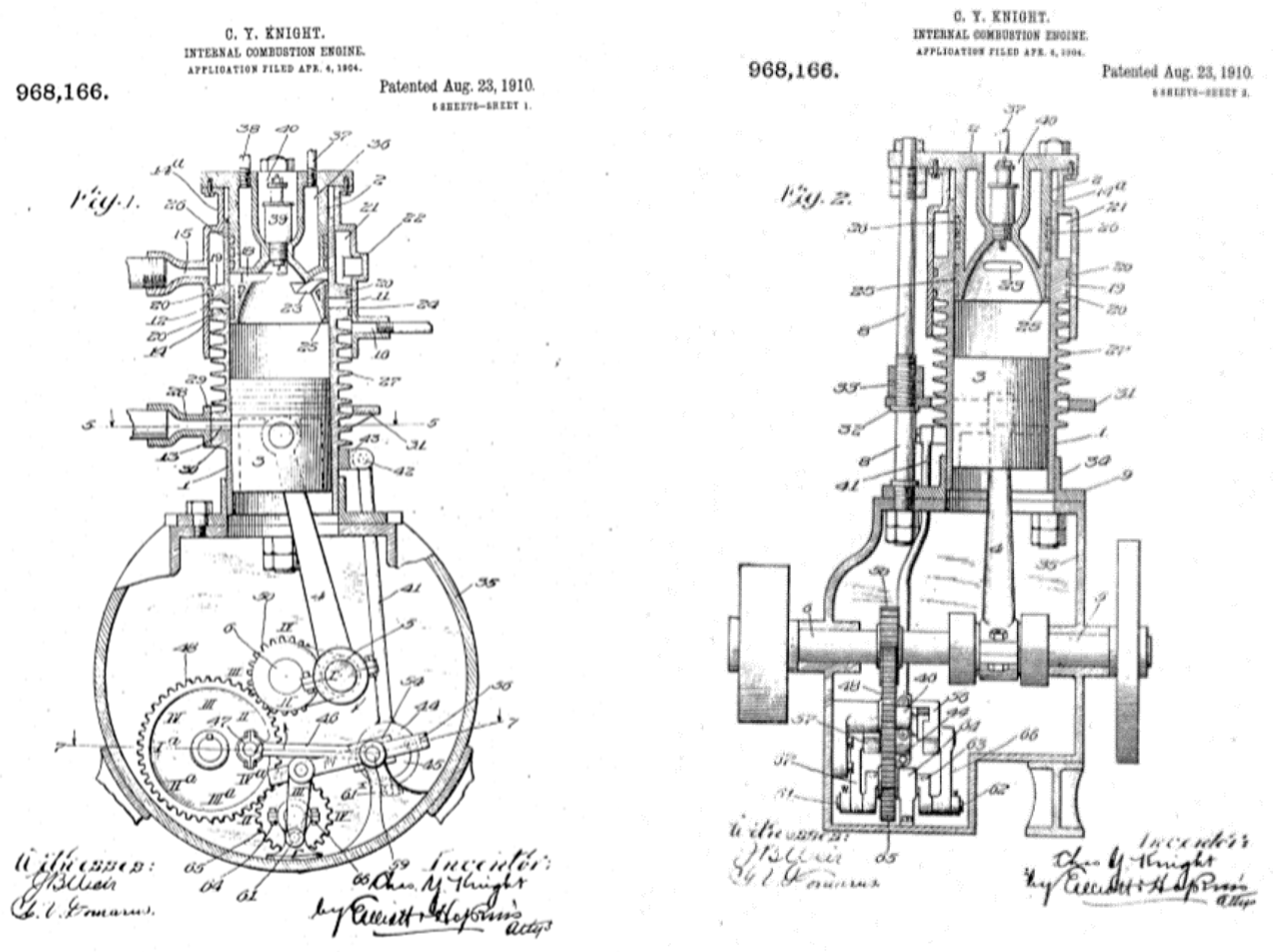
  3. Knight, C.Y. Internal Combustion Engine. U.S. Patent No. 968,166, 4 April 1904. [Google Scholar]
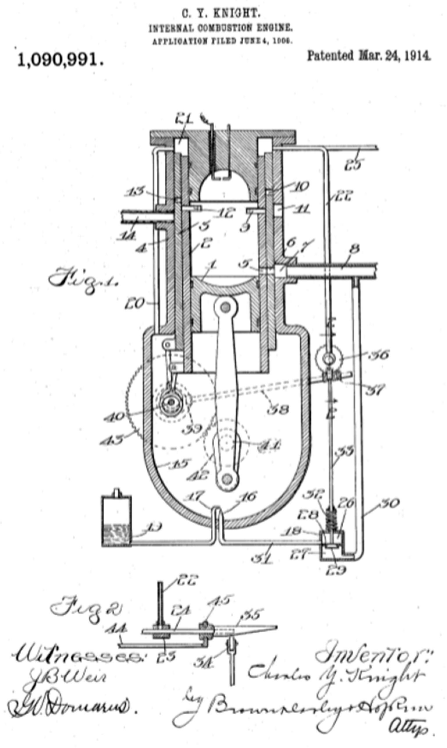
  4. Knight, C.Y. Internal Combustion Engine. U.S. Patent No. 1,090,991, 4 June 1906. [Google Scholar]
  5. Knight, C.Y. Internal Combustion Engine. U.S. Patent No. 1,136,143, 10 October 1908. [Google Scholar]
  6. Burt, P. Internal Combustion Engine. International Patent Application No. GB418,988x, 8 August 1909. [Google Scholar]
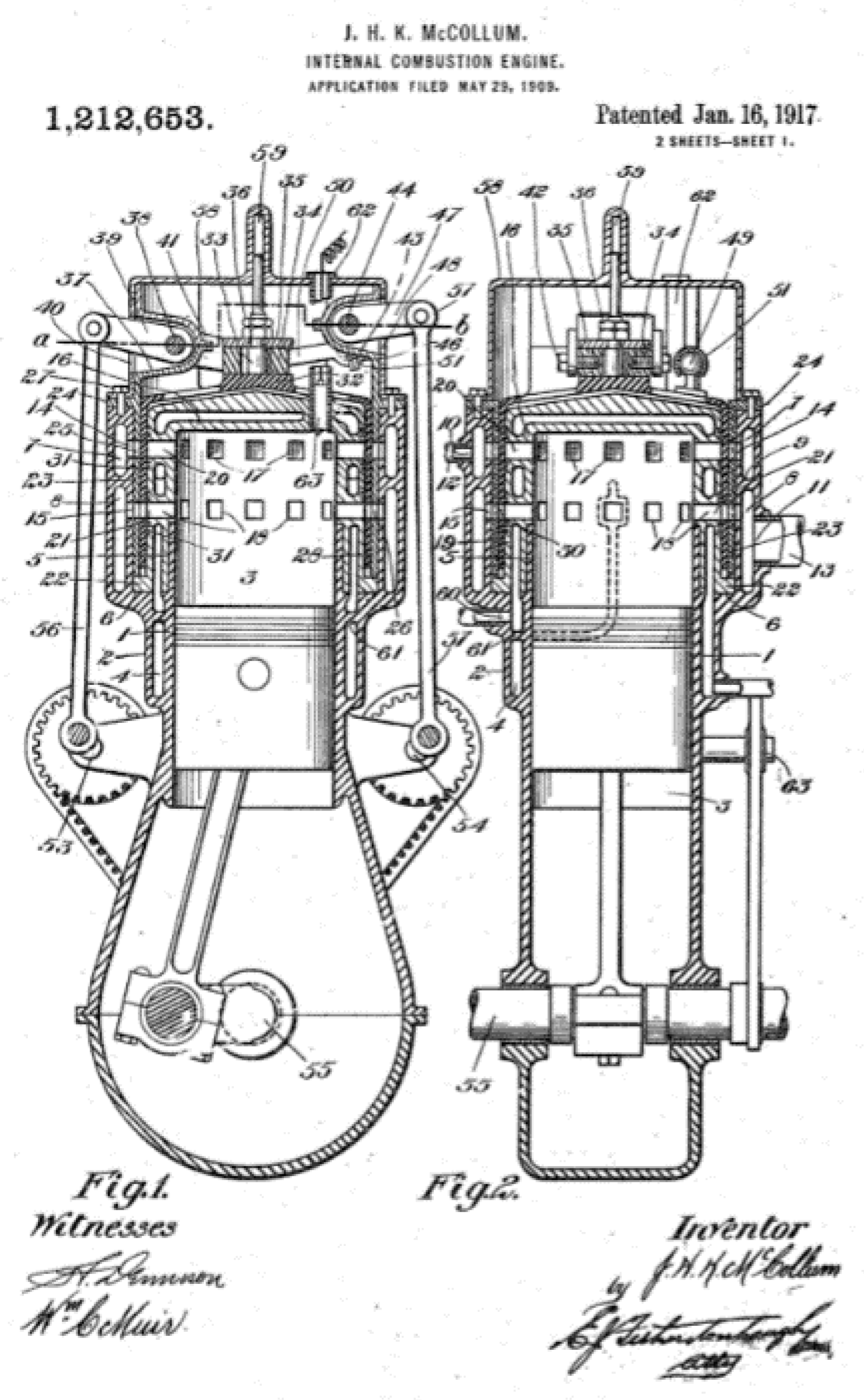
  7. McCollum, J.H.K. Internal Combustion Engine. International Patent Application No. GB409,216, 29 May 1909. [Google Scholar]
  8. Montagu, D.S.; Barrington, E.J.; Burgess-Wise, D. Daimler Coventry: The Full History of Britain’s Oldest Car Maker, 1st ed.; Patrick Stephens Ltd.: Somerset, UK, 1995; p. 114. [Google Scholar]
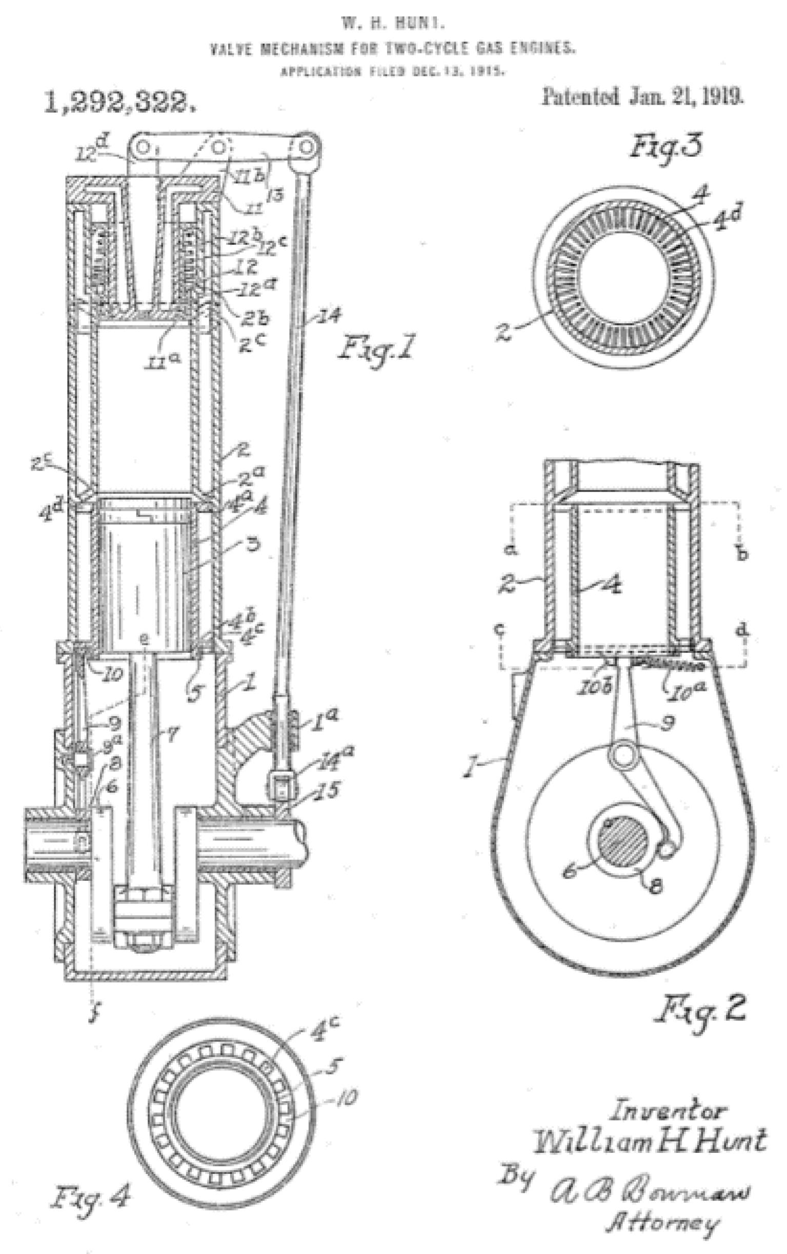
  9. Hunt, W.H. Valve Mechanism for Two-Stroke Gas Engine. U.S. Patent No. 1,292,322, 13 December 1915. [Google Scholar]
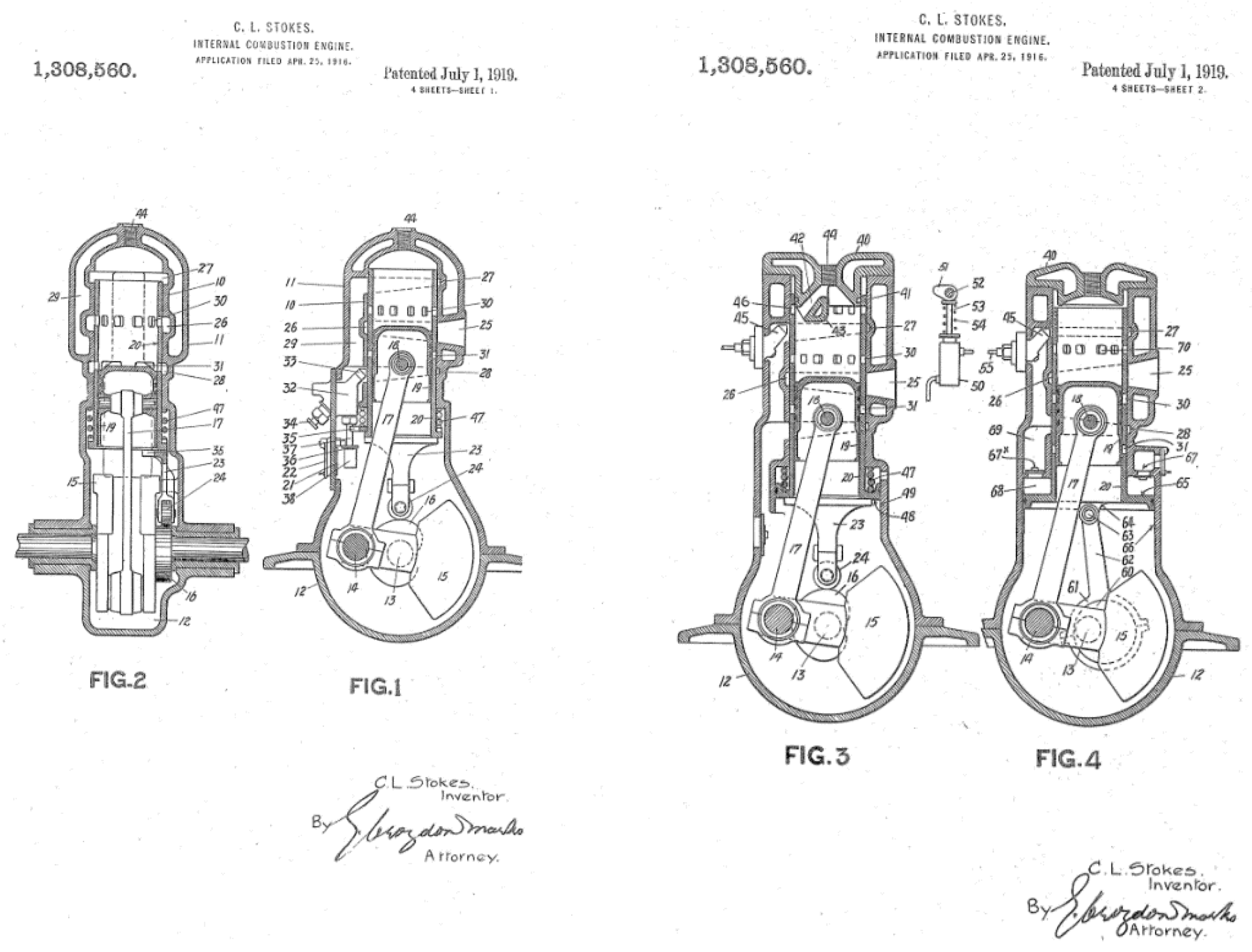
  10. Stokes, C.L. Internal Combustion Engine. U.S. Patent No. 1,308,560, 2 April 1916. [Google Scholar]
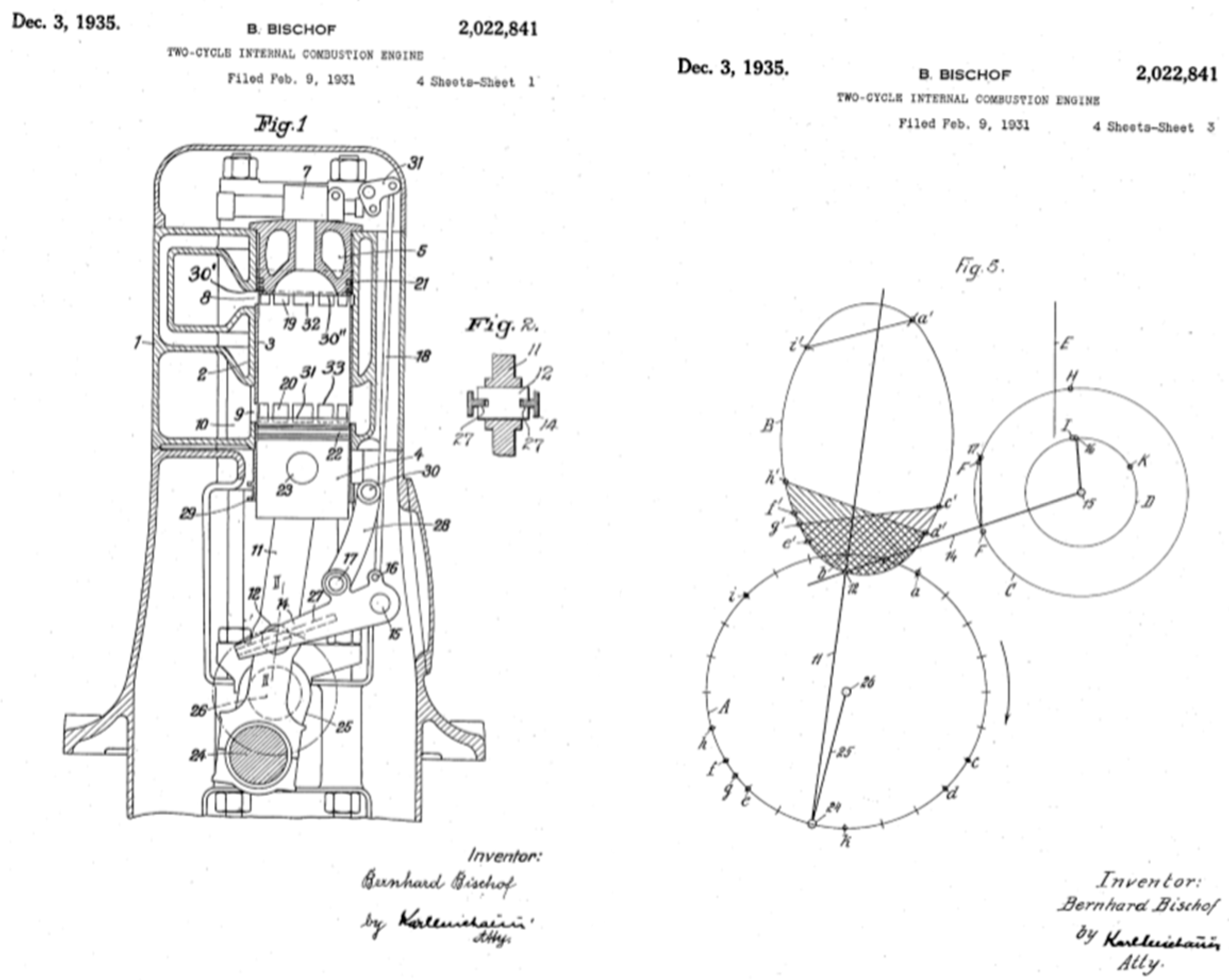
  11. Bischof, B. 2 Cycle Internal Combustion Engine. U.S. Patent No. 2,022,841, 9 February 1931. [Google Scholar]
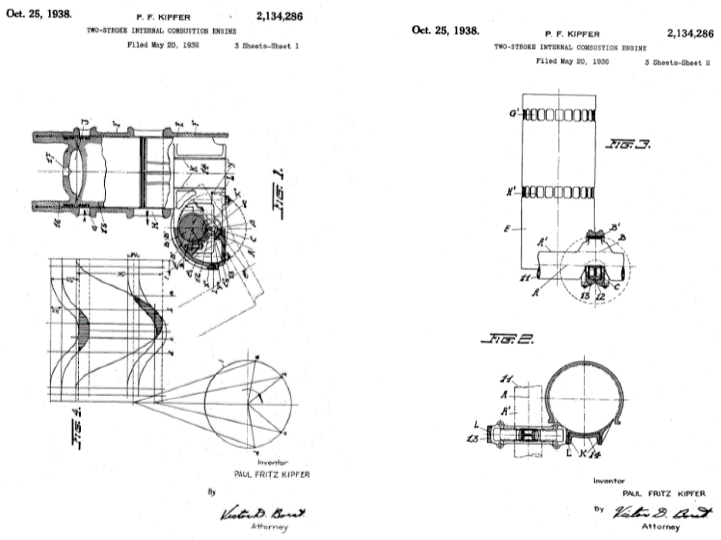
  12. Kipfer, P.F. Two-Stroke Internal Combustion Engine. U.S. Patent No. 2,134,286, 20 May 1936. [Google Scholar]
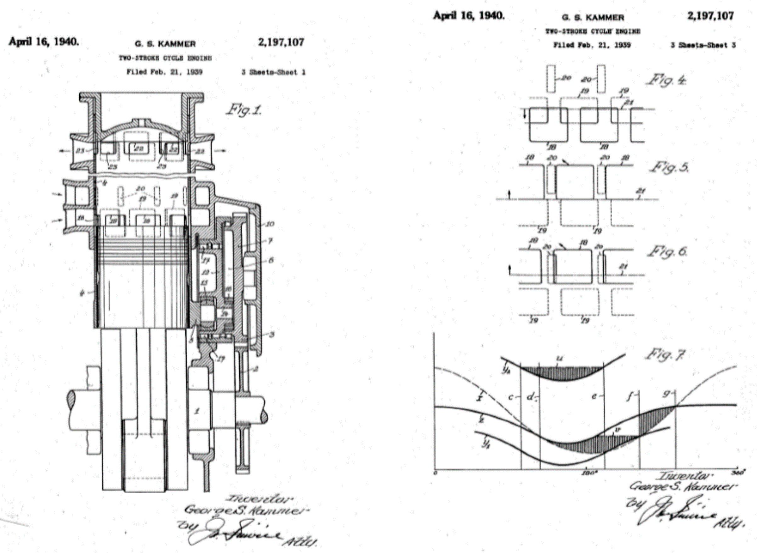
  13. Kammer, G.S. Two Stroke Cycle. U.S. Patent No. 2,197,107, 21 February 1939. [Google Scholar]
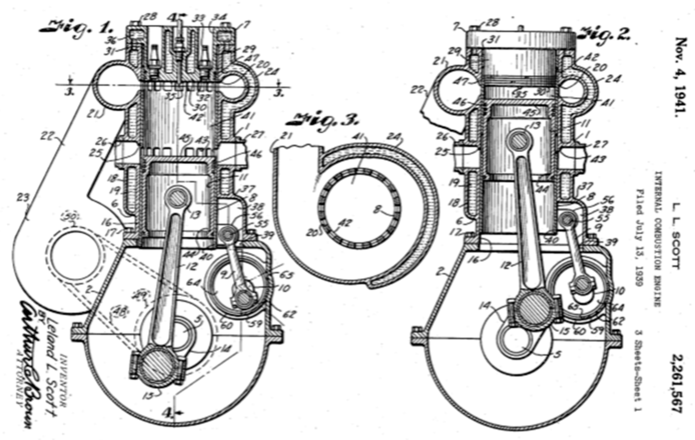
  14. Scott, L.L. GM. Internal Combustion Engine. U.S. Patent No. 22,611,567, 13 July 1939. [Google Scholar]
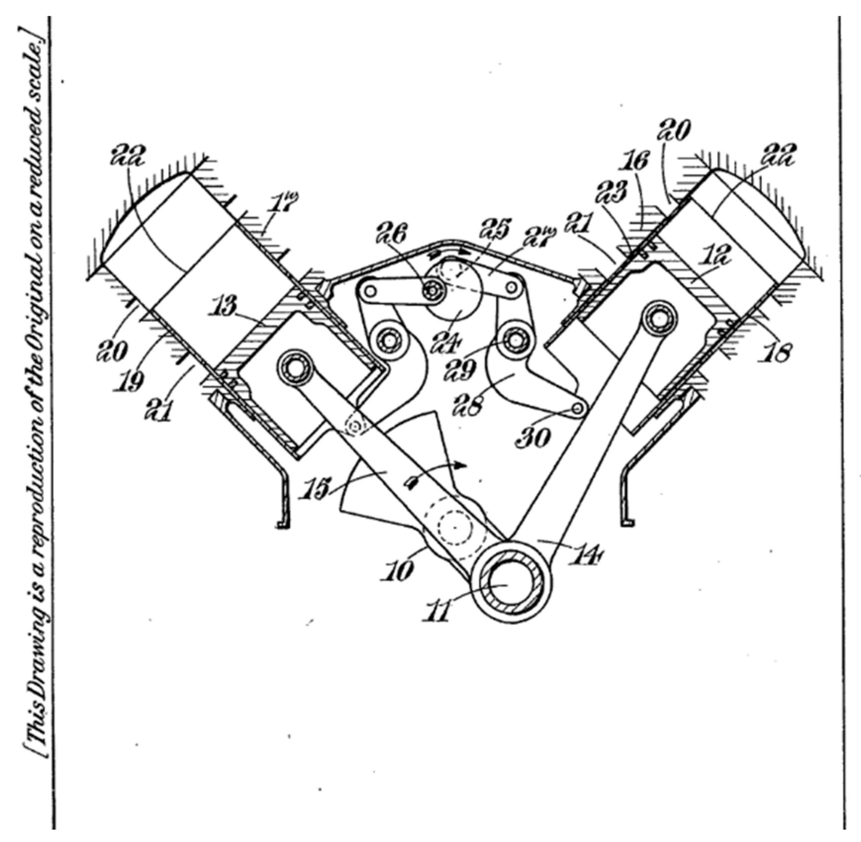
  15. Rowledge, A.J. Two Stroke Sleeve Drive of V Engines. International Patent Application No. GB524642A, 2 February 1939. [Google Scholar]
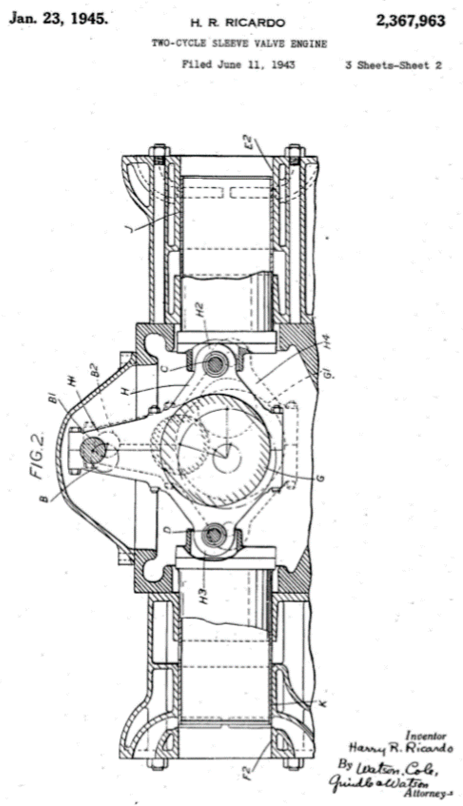
  16. Ricardo, H. Two Stroke Sleeve Valve Engine. U.S. Patent No. 2,367,963, 11 June 1943. [Google Scholar]
  17. Hiett, G.F.; Robson, J.V.B. A High-Power Two Cycle Sleeve Valve Engine for Aircraft. Aircraft. Eng. Burn. Publ. 1950, 22, 21–23. [Google Scholar] [CrossRef]
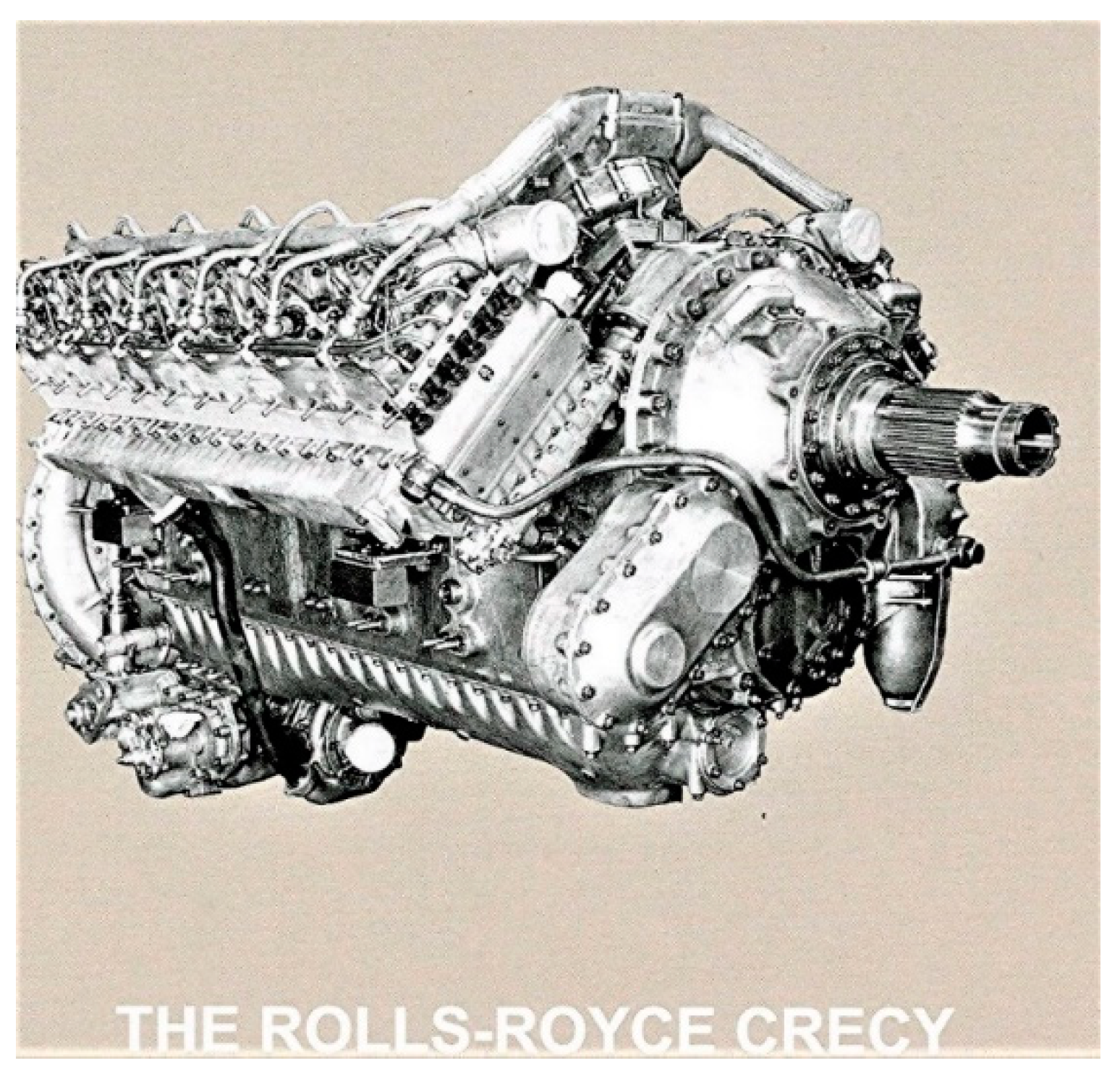
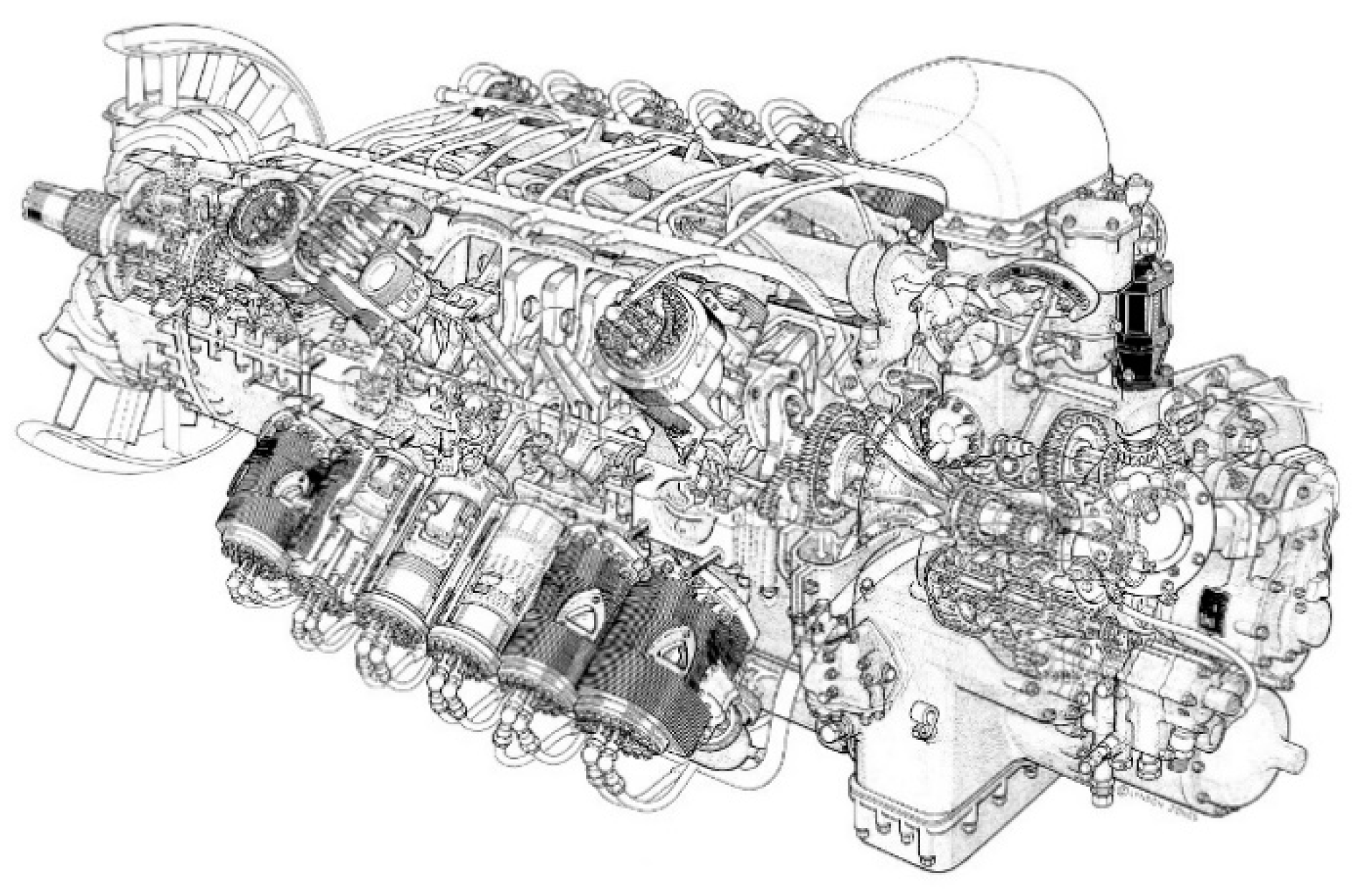
  18. Nahum, A.; Foster-Pegg, R.W.; Birch, D. The Rolls-Royce Crecy; Rolls-Royce Heritage Trust: Derby, UK, 1994; ISBN 1-872922-05-8. [Google Scholar]
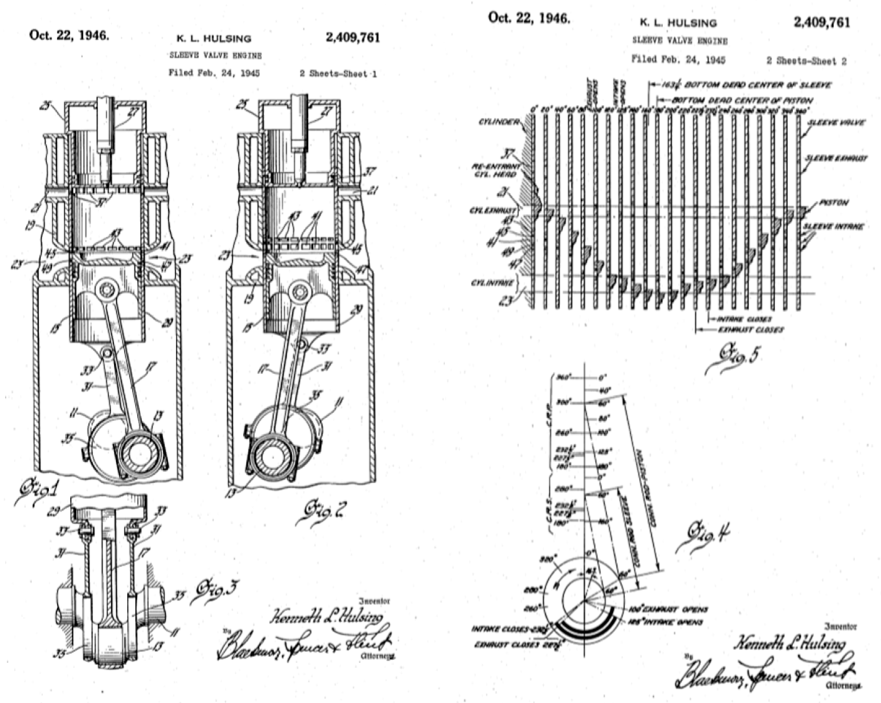
  19. Halsing, K. GM. Sleeve Valve Engine. U.S. Patent No. 2,409,761, 24 February 1945. [Google Scholar]
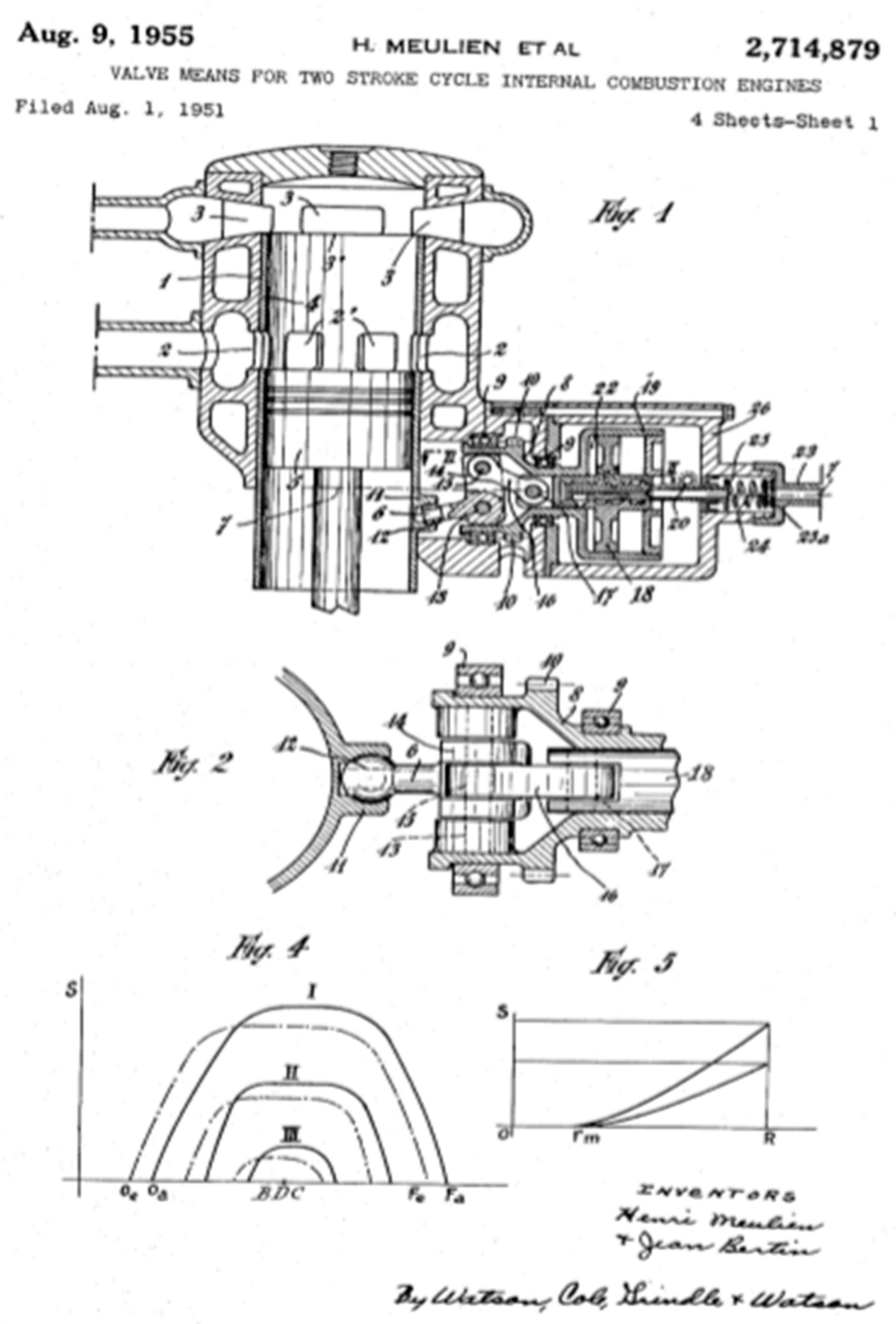
  20. Meulien, H.; Bertin, J. Valve Means for Two Stroke Cycle Internal Combustion Engines. U.S. Patent No. 2714879, 1 August 1951. [Google Scholar]
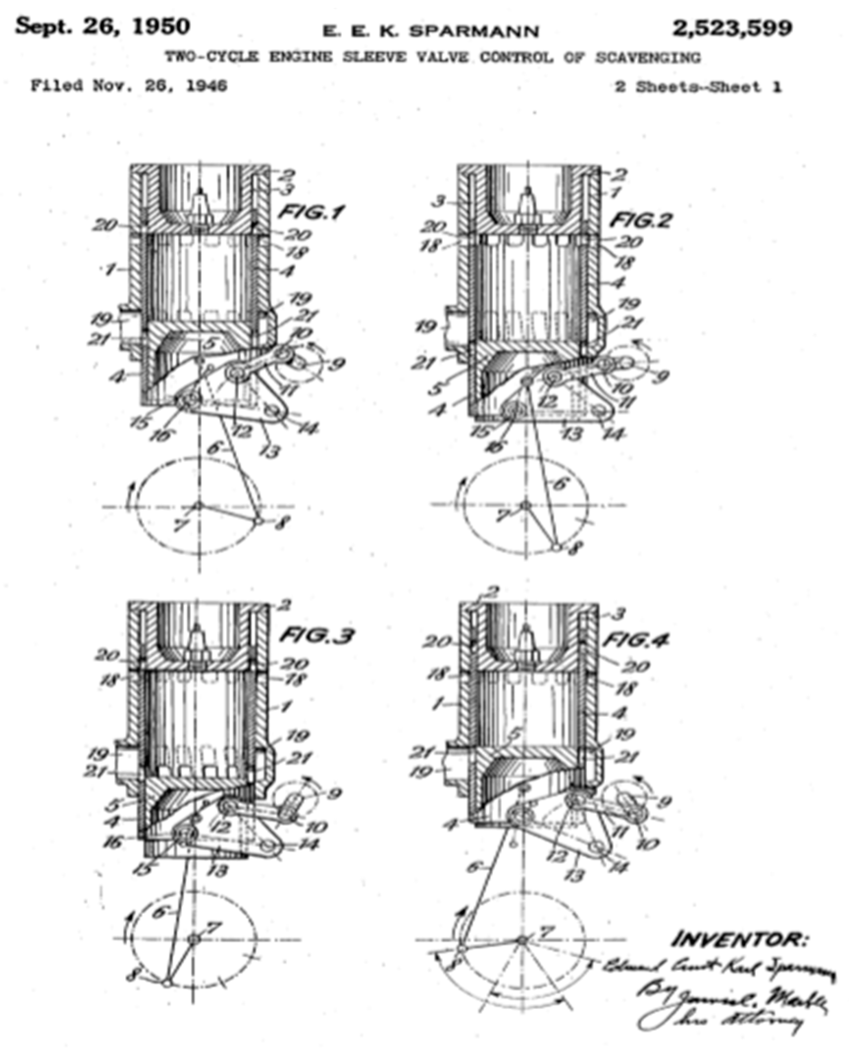
  21. Sparmann, E.E.K. Two Cycle Engine Sleeve Valve Control of Scavenging. U.S. Patent No. 2,523,599, 26 November 1946. [Google Scholar]
  22. Chen, Y.; Chen, C. Two Stroke Engine. U.S. Patent No. 6662764B2, 6 November 2003. [Google Scholar]
  23. Beninca, J.; Jones, M. Compound Drive for the Sleeve Valve of an Engine. International Patent Application No. WO2010094078A1, 26 August 2010. [Google Scholar]
  24. Cleeves, J.M. Single Piston Sleeve Valve with Optional Variable Compression Ratio Capability. U.S. Patent No. 9650951B2, 16 May 2017. [Google Scholar]
  25. Ellis, P. Sleeve Valve Engine. U.S. Patent No. 2017/009617A1, 12 January 2017. [Google Scholar]
  26. Pattakos, J. Rotary Sleeve Valve for Asymmetric Timing in Two Strokes. International Patent Application No. GB2563685A, 26 December 2018. [Google Scholar]
  27. Turner, J. Sleeve Valve Engine. International Patent Application No. GB2432398, 18 November 2005. [Google Scholar]
  28. Fedden, A.H.R. Bristol Aeroplane Company Improvements in or Relating to Internal Combustion Engines Having Sleeve Valves. International Patent Application No. GB425060A, 15 November 1935. [Google Scholar]
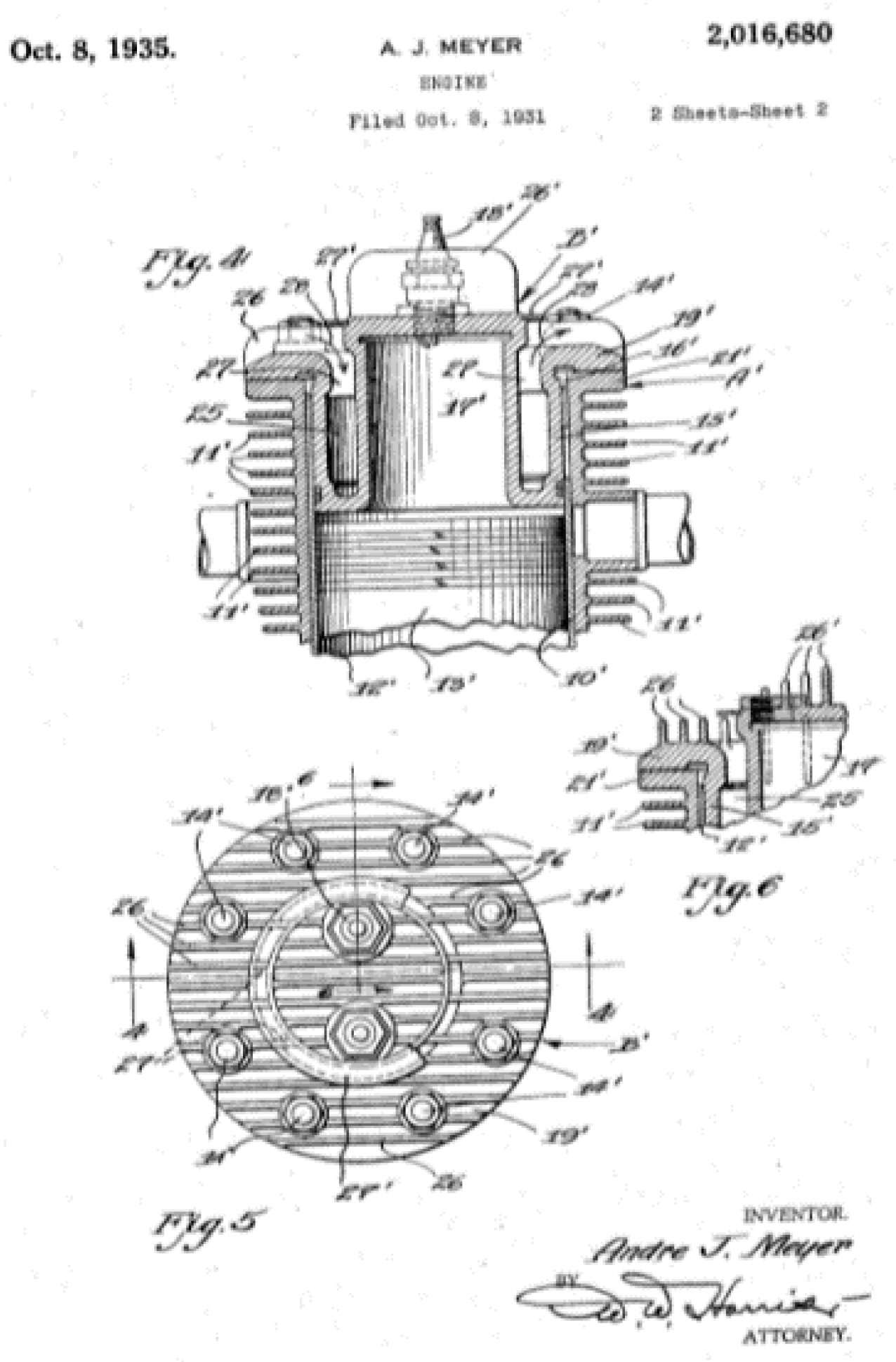
  29. Mayer, A.J. Continental Engine. U.S. Patent No. 2016680, 8 October 1931. [Google Scholar]
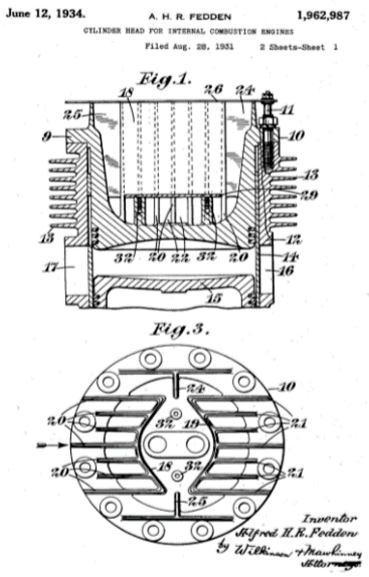
  30. Fedden, A.H.R. Bristol Aeroplane Company Cylinder Head for Internal Combustion Engine. U.S. Patent No. 1962987, 28 August 1931. [Google Scholar]
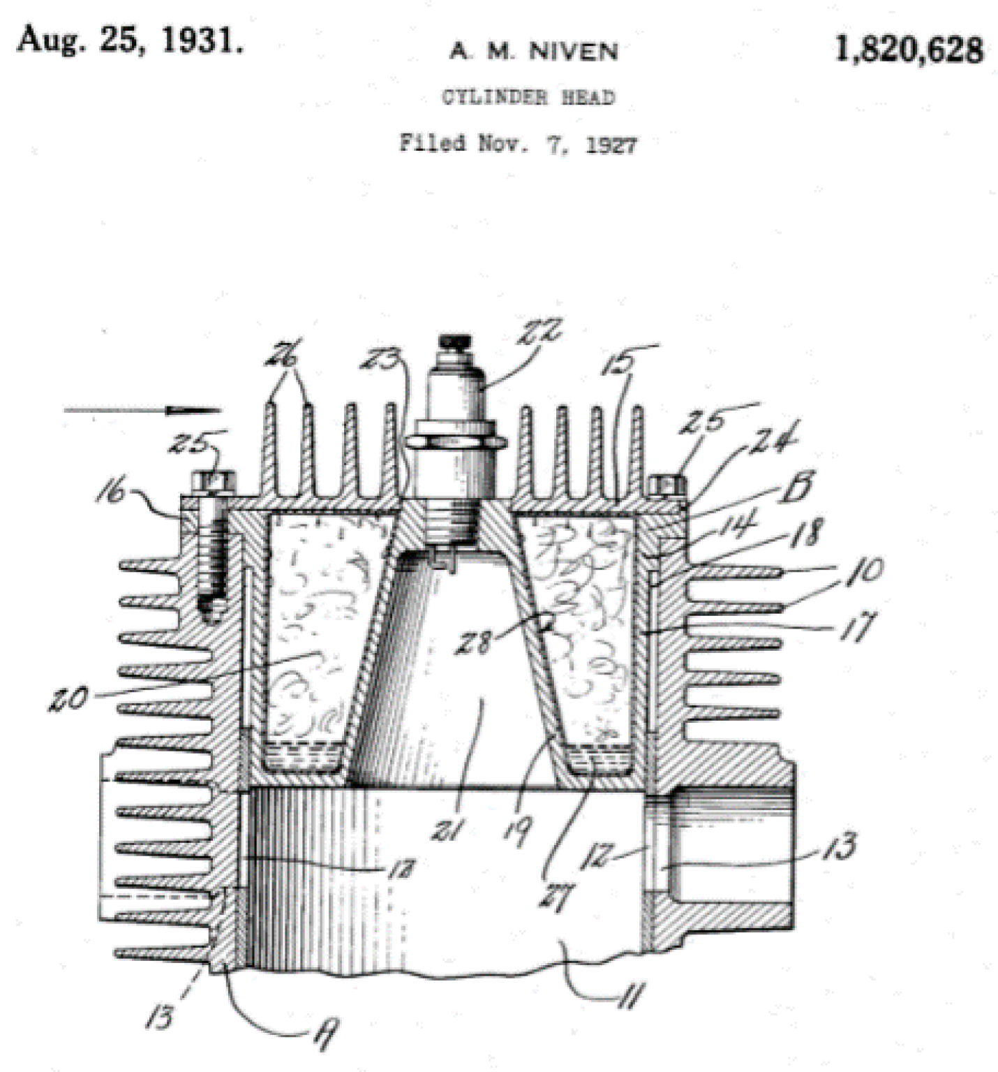
  31. Niven, A.M. Continental; Cylinder Head. U.S. Patent No. 1820628, 25 August 1931. [Google Scholar]
  32. Turner, J.W.; Monsma, J.P.L. An Investigation into the Port Timing of a Burt-McCollum Sleeve Valve and Its Interaction with a Simple Variable Compression Ratio Mechanism; SAE Technical Paper 2017-24-0168; SAE: Capri, Italy, 2017. [Google Scholar]
  33. Turner, J.W.G.; Head, R.A.; Chang, J.; Engineer, N.; Wijetunge, R.; Blundell, D.W.; Burke, P. Two-Stroke Engine Options for Automotive Use: A Fundamental Comparison of Different Potential Scavenging Arrangements for Medium-Duty Truck Applications; SAE Technical Paper 2019-01-0071; SAE: San Antonio, TX, USA, 2019. [Google Scholar]
Figure 1. C.Y. Knight patent for internal combustion engine US patent 968166 filed 4 April 1904. Reproduced with permission from US Patent Office. Copyright Publisher, 1910.
Energies 14 00616 g001
Figure 2. C.Y. Knight patent for internal combustion engine US patent 1090991 filed 4 June 1906. Reproduced with permission from US Patent Office. Copyright Publisher, 1914.
Energies 14 00616 g002
Figure 3. James McCollum, 29 May 1909, internal combustion engine, Patent US 1212653. Reproduced with permission from US patent office Copyright Publisher, 1917.
Energies 14 00616 g003
Figure 4. Peter Burt, Argyll Limited, 5 August 1910, an improved internal combustion engine CA 133050A. Reproduced with permission from US Patent Office, Copyright Publisher, 1910.
Energies 14 00616 g004
Figure 5. W.H. Hunt 13 December 1915, valve mechanism for two-stroke gas engine US 1292322. Reproduced with permission from US Patent. Copyright Publisher, 1919.
Energies 14 00616 g005
Figure 6. C.L Stokes, 2 April 1916, internal combustion engine US 1308560. Reproduced with permission from US Patent Office. Copyright Publisher, 1919.
Energies 14 00616 g006
Figure 7. B. Bischof, 9 February1931, two-stroke internal combustion engine US 2022841. Reproduced with permission from US patent Office. Copyright Publisher, 1935.
Energies 14 00616 g007
Figure 8. Kipfer 20 May 1936, two-stroke internal combustion engine US 2134286. Reproduced with permission from US patent Office. Copyright Publisher, 1938.
Energies 14 00616 g008
Figure 9. G.S Kammer 21 February 1939, two-stroke cycle US 2197107. Reproduced with permission from US Patent Office. Copyright Publisher, 1940.
Energies 14 00616 g009
Figure 10. L.L. Scott GM, 13 July 1939: Internal combustion engine US 2261156. Reproduced with permission from US Patent Office. Copyright Publisher, 1941.
Energies 14 00616 g010
Figure 11. A.J. Rowledge Rolls-Royce 2 February 1939: two-stroke sleeve drive of V engine-configuration engines GB 524642A. Reproduced with permission from GB Patent Office Copyright Publisher, 1934.
Energies 14 00616 g011
Figure 12. The Rolls-Royce Crecy sleeve valve drive arrangement. Reproduced with permission from New Zealand Rolls-Royce & Bentley Club Inc Copyright Publisher, 2007.
Energies 14 00616 g012
Figure 13. H Ricardo 11 June 1943, Two stroke sleeve valve engine US 2367963. Reproduced with permission from US Patent Office. Copyright Publisher, 1943.
Energies 14 00616 g013
Figure 14. Rolls-Royce Crecy engine 12-cylinder two-stroke sleeve valve direct fuel injection 90 degree V aircraft piston engine. Reproduced with permission from WW2 aircraft.net Copyright Publisher, Year1989.
Energies 14 00616 g014
Figure 15. K Halsing GM 24 February 1945, sleeve valve engine US 2409761. Reproduced with permission from US Patent Office. Copyright Publisher, 1946.
Energies 14 00616 g015
Figure 16. H. Meulien et al. SNECMA 1 August 1951, Valve US 2714879. Reproduced with permission e 1951.
Energies 14 00616 g016
Figure 17. E.E.K. Sparmann 26 November 1946, two-cycle engine sleeve valve control of scavenging US 2523599. Reproduced with permission from US Patent Office. Copyright Publisher, 1950.
Energies 14 00616 g017
Figure 18. Rolls-Royce Pennine 24-cylinder sleeve valve 2 stroke 90°X Engine 1945. Reproduced with permission from Old Machine Press]. Copyright Publisher, 2018.
Energies 14 00616 g018
Figure 19. Y. Chen 6 November 2003, two-stroke engine US 6662764B2. Reproduced with permission from US Patent Office. Copyright Publisher, 2003.
Energies 14 00616 g019
Figure 20. J Beninca 26 August 2010, compound drive for the sleeve valve of an engine WO 2010094078A1. Reproduced with permission from World Intellectual Property Organization. Copyright Publisher, 2010.
Energies 14 00616 g020
Figure 21. J. Cleeves 16 May 2017, Single piston sleeve valve with optional variable compression ratio capability US 9650951. Reproduced with permission from US Patent Office Copyright Publisher, 2017.
Energies 14 00616 g021
Figure 22. P. Ellis 12 January 2017, sleeve valve engine US 2017/009617A1. Reproduced with permission from US Patent Office. Copyright Publisher, 2017.
Energies 14 00616 g022
Figure 23. Pattakos December 2018 rotary sleeve valve for asymmetric timing in two strokes GB 2563685. Reproduced with permission from GB Patent Office Copyright Publisher, 2018.
Energies 14 00616 g023
Figure 24. J. Turner Lotus 18 November 2005, sleeve valve engine 2005 GB 2432398A. Reproduced with permission from GB Patent Office. Copyright Publisher, 2005.
Energies 14 00616 g024
Figure 25. Junk Head Cooling A.J. Mayer. 8 October 1931 Continental Engine US 2016680. Reproduced with permission from US Patent Office Copyright Publisher, 1935.
Energies 14 00616 g025
Figure 26. A.H.R Fedden, Bristol Aeroplane Company Cylinder head for internal combustion engine 28 August 1931, US 1962987. Reproduced with permission from US Patent Office. Copyright Publisher, 1934.
Energies 14 00616 g026
Figure 27. A.M. Niven Continental, cylinder head 25 August 1931, US 1820628. Reproduced with permission from US Patent Office Copyright Publisher, 1931.
Energies 14 00616 g027
Publisher’s Note: MDPI stays neutral with regard to jurisdictional claims in published maps and institutional affiliations.

