Article

Directional Hydraulic Fracturing (DHF) of the Roof, as an Element of Rock Burst Prevention in the Light of Underground Observations and Numerical Modelling

1
Department of Geomechanics and Underground Construction, Faculty of Mining, Safety Engineering and Industrial Automation, Silesian University of Technology, ul. Akademicka 2, 44-100 Gliwice, Poland
2
“Marcel” Coal Mine, Oddział Kopalnia Węgla Kamiennego ROW, Polska Grupa Górnicza S.A., ul. Korfantego 52, 44-310 Radlin, Poland
3
“Rydułtowy” Coal Mine, Oddział Kopalnia Węgla Kamiennego ROW, Polska Grupa Górnicza S.A., ul. Leona 2, 44-280 Rydułtowy, Poland
*
Author to whom correspondence should be addressed.
Energies 2021, 14(3), 562; https://doi.org/10.3390/en14030562
Submission received: 7 December 2020 / Revised: 16 January 2021 / Accepted: 19 January 2021 / Published: 22 January 2021

Abstract

:
The following article analyzes the effectiveness of directional hydraulic fracturing (DHF) as a method of rock burst prevention, used in black coal mining with a longwall system. In order to define changes in seismic activity due to DHF at the “Rydułtowy” Black Coal Mine (Upper Silesia, Poland), observations were made regarding the seismic activity of the rock mass during coal mining with a longwall system using roof layers collapse. The seismic activity was recorded in the area of the longwall itself, where, on a part of the runway, the rock mass was expanded before the face of the wall by interrupting the continuity of the rock layers using DHF. The following article presents measurements in the form of the number and the shock energy in the area of the observed longwall, which took place before and after the use of DHF. The second part of the article unveils the results of numerical modeling using the discrete element method, allowing to track the formation of goafs for the variant that does not take DHF into consideration, as well as with modeled fractures tracing DHF carried out in accordance with the technology used at “Rydułtowy” coal mine.

1. Introduction

Hydraulic fracturing, as a method of continuum disintegration, is used for numerous purposes related to the need for rock structure destruction using high-pressure liquid injection. This technology has been used since the 1950s, mainly in the United States [1], and the key feature of it is the disintegration of the rock mass in order to obtain shale gas [2,3,4].
Nevertheless, this method has also been used in acquiring another energy resource, i.e., in deep-sea mining of coal seams. When it comes to black coal mining, hydraulic fracturing can be used, among others, to prevent rock bursts [5]; to reduce stress within the rock mass in order to uphold the stability of corridor excavations [6]; to obtain methane accompanying coal seams [7], what contributes to the increase of safety during mining operations [8].
What is more, hydraulic fracturing also allows to carry out research on the stress state within the rock mass by defining the value of liquid pressure needed for the formation of cracks and after that by opening and tightening the crack within the rock mass [9,10,11].
In this article, the issue of hydraulic fracturing was taken into consideration referring to the activities of underground black coal mines exposed to rock bursts, which occur not only in many black coal and copper ore mines in Poland [12,13], but also wherever exploitation is carried out in great depths within rocks considered to have good endurance and stiffness as well as, in a result, high ability to accumulate elastic energy [14,15,16,17,18].
Using hydraulic fracturing allows the endurance of the layers to be broken, what reduces the elastic energy accumulated within them. In addition to the main effect of stress reduction within the rock mass, properly conducted fracturing helps with the formation of a mining collapse and improves degassing of the rock mass [19,20,21,22]. An alternative method of rock bust prevention to hydraulic fracturing may be the use of explosives, whose effectiveness has been proven in laboratory research [23] and in situ observations [24,25,26].
A particular type of hydraulic fracturing is directional hydraulic fracturing (DHF), which is the object of the following article. This method is a subject of [22,23,27,28] creating groves within the rock mass, which split the rock layers into blocks of size depending on the density and directions of DHF. As a consequence of the initial groove formed in the hole, the direction of the produced fracture is perpendicular to the borehole. Using special blades that are placed into the hole on the drill rod, initial grooves are made to cause a wedge-shaped incision to be made on the side surface. Then the hole needs to be filled as close as possible to the spore opening. DHF’s key step is to push the liquid into the hole, the strain of which, concentrated at the sharp end of the original grove, allows the continuity of the rock layers in the plane to propagate and crack perpendicular to the path of the hole. The formation of a rift is manifested by a sudden drop in pressure of the injected liquid.
The range of hydraulic fracturing in the carboniferous rocks of the Upper Silesian Coal Basin varies from 15 to 5 m with a sufficiently high pressure and water injection rate, and the value of the liquid pressure required to build a crack should be determined on the basis of the dependency (1) [29].
P = 1.3 ( P z * + R t )
where
  • P z * —rock mass pressure based on the depth, exploitation events, geological disturbances,
  • R t —tension strength of rocks in the plane of the created fracture
The effectiveness of DHF relies on both the hardness parameters of the rocks and the rock mass structure. The proper use of DHF breaks the continuity of the rock layers in a narrowly defined plane, thus reducing the stress condition of the rock mass and, as a consequence, reducing the energy of potential rock bursts [30,31] and reducing the convergence of headings [32].
The numerical models presented so far have focused on the effect of DHF on the condition of rocks in the immediate vicinity of individual fractures [28,30,31], whereas this paper introduces a simulation in which DHF has been modeled six times over a 120 m wall length. Creating such a model has helped to show significant reduction of the kinetic energy produced after hydraulic fracturing operation.
The key intention of this article was to present the usefulness of hydraulic fracturing by using the example of mining and geological conditions of a black coal mine located in the Upper Silesian Coal Basin. Furthermore, the aim was to analyze the mechanism of goaf formation after the use of hydraulic fracturing within roof layers using numerical simulations performed in the UDEC (Universal Distinct Element Code) program [33]. Hereby, the results of the measurements of the seismic activity in the rock mass throughout coal mining with the longwall system, presented in this article, along with the numerical simulations which map this exploitation, confirm the effectiveness of the directional hydraulic fracturing (DHF) of rock bursts prevention.

2. Examples of Using Directional Hydraulic Fracturing of the Roof at PGG S.A. Unit KWK ROW Ruch Rydultowy Coal Mine Within Longwall II-E1, Coal Seam 713/1-2

In the first part of this article, the usefulness of hydraulic fracturing is presented for the degradation of the rock mass structure and, as a result, reducing the risk of rock bursts. It is presented on the example of II-E1 longwall in coal seam 713/1-2 (Figure 1) in KWK Ruch Rydultowy coal mine, which is a part of PGG S.A., the biggest black coal mining company in Europe.
In the area of the mentioned longwall, the 713/1-2 coal seam lies at a depth between approximately 1145 m to approximately 1185 m, its thickness, alongside the occurring overgrowths, ranges from 2.40–2.90 m, and the slope varies from 3–6 degrees. Throughout the exploitation of this seam, there is a high risk of rock bursts, a high methane hazard, and a moderate water hazard. Moreover, the coal has a tendency to burst out gases and rocks.
In the direct roof of the seam there can be found clay shales and local sandstones. At the floor of the seam there are clay and sand shales, and coal inserts with thickness of 0.39 m and 0.30 m.
The endurance parameters of the surrounding rocks and the seam are as follows:
  • Compressive strength of roof rocks: 40.9: 79.0 MPa
  • Compressive strength of floor rocks: 38.4: 48.0 MPa
  • Compressive strength of coal in seam 713/1-2: 14.20 MPa.
The exploitation of coal seam 713/1-2 was carried out at a distance of about 100 m below the goafs created in seam 703/1 and about 60 m below the goafs created in seam 706. What is more, in the area of exploitation there were edges of seam 620/1-2 at a vertical distance of approximately 575 m and seam 624 at a vertical distance of about 450 m.
During the drilling of the mining excavation contouring (separating) the plot of longwall II E-1, there was found a fault with an amplitude equal to h = 0.6 m, which drops the seam towards S. It was detected in the mining gallery 2-E1 throughout the area of 479.5 m.
The longwall I-E1 (Figure 1) was launched in 2015 as the first one in coal seam 713/1-2 within the examined area. During its exploitation, 112 shocks were registered, including six high-energy shocks with energy stretching from 105–107 J.
In order to illustrate the number and intensity of shocks happening during the performance of this longwall, the results of measurements of seismic activity were summed up in Table 1 in the form of:
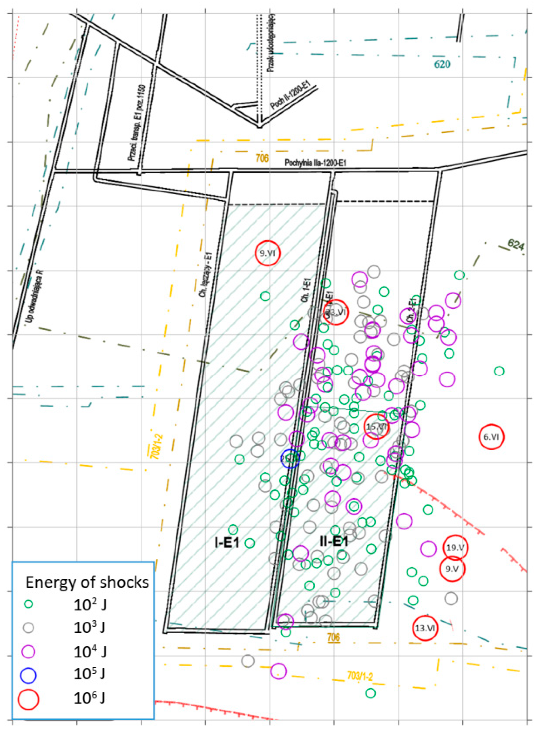
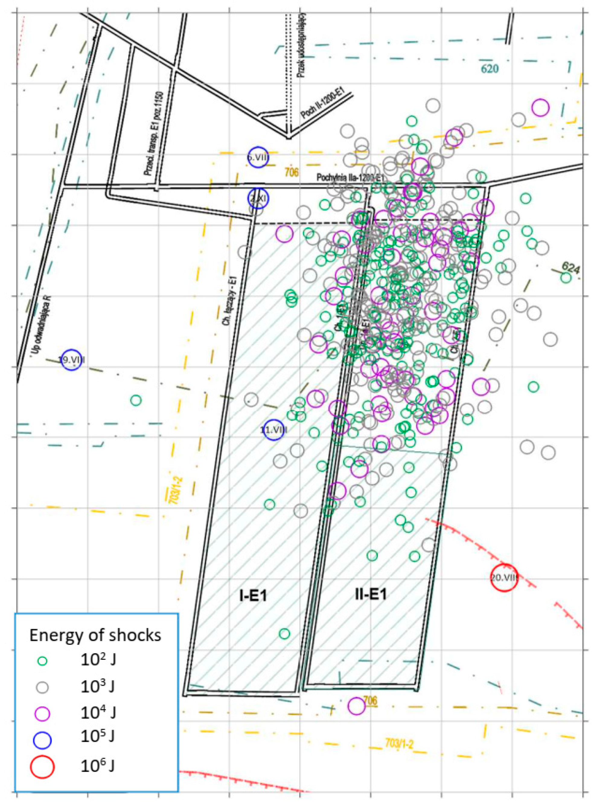
  • The number of shocks for each row from 102–108 J
  • The monthly number of shocks
  • Monthly summary energy
  • Monthly summary energy divided by the monthly production volume
  • Maximum energy of a single shock
Monthly summary energy divided by the monthly longwall length.
Exploitation of the next longwall II-E1 started in March 2017 and was carried out until November 2017 (Figure 1). The longwall was excavated in a longitudinal system with rock caving, in the direction away from the field. Its length was about 150 m, while the panel length was about 670 m. In the forecast of rock bursts hazard in the zone of longwall II-E1, the occurrence of shocks with maximum energy of 108 J was predicted.
For longwall II-E1, as part of rock burst prevention, it was determined, among others, that:
  • The maximum daily progress during the start-up period was 4 m per day, and on the remaining length it was 6 m per day.
  • Areas of specific risk of rock bursts have been designated: in longwall galleries, i.e., gallery 1a-E1 and 2-E1, as well as on sections of wall II-E1 with individual support.
  • Constant seismological observation was carried out.
  • Seismic and acoustic observation was carried out using two geophones fitted into the longwall galleries before the face of the wall.
  • Each day, small-diameter survey drillings were performed: in three measuring belts in the wall and in two measuring belts in longwall galleries (15 m and 30 m before the face of the wall).
From the very beginning of longwall II-E1, the exploitation was accompanied by numerous shocks. They have been listed in Table 2 and graphically presented in Figure 2 until the first hydraulic fracturing. Before the commencement of rock burst prevention, based on using hydraulic fracturing, until July 2017, in longwall II-E1 there were 212 shocks with energy stretching from 102–106 J. The shocks recorded during this period were not directly affecting the condition of the supports and were not responsible for any deterioration of the infrastructure in the longwall area.
In relation to high seismic activity accompanying the exploitation of seam 713/1-2 at longwall II-E1 and the difficulties with getting a full collapse behind the advancing face, especially in the section of the sandstone layer in the direct seam roof (Figure 1), a decision was made to use active rock burst prevention, based on the execution of DHF of the roof. These treatments were carried out from holes of 6–7 m in length and 48 mm in diameter, drilled perpendicular to the carbon sidewall of the longwall face at an angle of +45 degrees in the direction of the longwall advancement, at intervals of 20–25 m. The implemented hydraulic fracturing scheme is shown in Figure 3.
From July 9, 2017 until November 19, 2017 DHF was used 20 times, while the number of holes used for hydraulic fracturing was fluctuating between 3–7, and each time was depending on roof conditions present within the longwall and the proceeding collapse. DHF was carried out with time intervals of about one week, and this translated to the minimum of nine running meters up to the maximum of 22 running meters of longwall advancement between consecutive DHFs. The pressure added during the hydraulic fracturing was fluctuating between 20 MPa and 26 MPa; in the meantime, after a crack was made, it dropped down to the minimum of 7 MPa. The making of the crack was accompanied by clatters, crackles, and after that an outflow of fluid from the rock mass.
During the period of the hydraulic fracturing being carried out in the area of the longwall, a total number of 518 shocks was registered. Five high-energy shocks were registered, with energy expanding from 105–106 J. In regard to the period leading up to the use of prevention, the value of summary monthly energy of the registered shocks had gone down. There was also a change in quantitative distribution of shocks, i.e., the number of shocks with energy around 103 J was increased in relations to higher-energy shocks, along the preserved progress in the longwall based on the stage of its start. The specification of shocks registered during the performance of the hydraulic fracturing was concluded in Table 3 and presented in Figure 4.
The comparison of the seismic behavior with the rock mass during the exploitation of the longwall studied clearly shows a decline in the frequency of the most harmful phenomena (rock bursts with energy above 1e6 J) and a rise in the number of low-energy bursts at the same time.
The amount of energy spent by the rock mass in relation to the volume of the excavation is also significant with regard to the variable pace of longwall front development. By analyzing these results, it is also possible to validate major variations between the operation using DHF (72.1 J/t in August 2017) and the pre-treatment time (279.3 J/t in June 2017).

3. Analyzing the Behavior of the Rock Mass Subjected to Hydraulic Fracturing Based on Numerical Modeling

Numerical modeling of rock mass, mining excavations, especially of mineral exploitation, allows us to trace the stress and strain states with the rock mass, which can be helpful when choosing the right excavation support [34,35], designing exploitation systems [36,37,38], anticipating threats [24], analyzing the staidness of excavation sites, and when anticipating the influence of exploitation on the surface of the terrain and the neighboring mining excavations [39].
Despite the fact that the methods based on the solutions of continuum (finite element method, finite difference method) are widely used for modeling the rock mass. On the other hand, they do not allow the simulation of cracks, displacements of dislodged rock solids, and the possible areas of destruction are most commonly modeled through yielding of the material. That is why a good alternative that lets us map the discontinuity of the rock mass is using the discrete elements method, upon which the UDEC (Universal Distinct Element Code) program, among others, is based, which was worked out and is being developed by Itasca Company [33].
Simulations of longwall exploitation by using the UDEC program were carried out both on flat models [40,41,42,43], and spatial models [44]. Adopting the spatial models allows more accuracy with mapping the geometry of rock mass in the vicinity of the exploited coal seam; however, due to the need of modeling quite a large volume, it is difficult and time-consuming to carry out calculations for a dense network of discontinuities simulating rock collapse and the formation of post-excavation goafs.
Therefore, adopting the flat model is more favorable and allows to simulate the behavior of cracking rocks in the roof of the exploited seam [45], and defining the correspondently dense network of discontinuities allows to simulate the formation of cave-in rubble filling out the space left from the exploited coal seam [46].
In order to evaluate the influence of hydraulic fracturing on the condition of the rock mass around the exploited coal seam by using the UDEC program, based on the discrete elements method, a numerical model was built with size 175 m per 50 m, mapping the geologic and mining situation of longwall II-E1 within coal seam 713/1-2.
In this model, specific lithological layers were mapped, which were present in the vicinity of the exploited coal seam, by adopting diversified block sizes (diversified discontinuity density) for them (Figure 5).
For the part of the model mapping the bottom layer of the 10-m-thick seam, made of clay shale and sandy shale, a homogenous system model without division into blocks was adopted.
Coal seam 713/1-2 was modeled as a 2.8-m-thick layer (L2), in which at the length of 90 m, rectangular blocks 1 m wide were separated, and their removal during the next stages of the simulation reflected the progress of the longwall face.
Above the exploited seam, a 9 m layer of sandy shale (L3) was modeled, which was divided into blocks in the shape of equilateral triangles, with side length of 1.15 m.
The next layer in the model (L4) was separated as a layer of clay shale, which was divided into square blocks with side length of 2 m. The next layer (L5) was also divided into square-shaped blocks with twice the dimensions.
Moreover, there were discontinuities generated in the model, representing the surfaces of the fractured layers bursts, which were made due to the use of DHF. The whole of the model was discretized by the division into triangular-shaped elements with the maximum side length of 2 m.
The model assumed displacement boundary conditions by immobilizing the bottom and side walls in directions perpendicular to them, as well as by imposing a vertical stress of 26 MPa (which is the product of the average volumetric weight of the overlying rocks and the depth of the modeled seam) upon the upper wall of the model, what corresponds with the original stress around the area of longwall II-E1 in coal seam 713/1-2, which was carried out in the depth ranging from 1145–1185 m.
The initial state of the model was established as a result of its equilibrium after the above-described boundary conditions were set, which generated vertical stresses of 26 MPa and horizontal stresses close to 11 MPa.
In order to receive a more detailed mapping of the mining conditions, structural elements were used in the model, which simulated the activity of a mechanized support, with acting on the roof over a length of 4 m with seven props with a stiffness of 50MN/m.
For the material forming the model, elastic endurance parameters were assumed, defined by elastic bulk and shear modulus values of 16.6 and 7.7 GPa respectively (Young’s modulus 20 GPa, Poisson’s ratio 0.3), with density of 2400 kg/m3.
For the joints between the blocks, an elastic model was assumed, with the Coulomb model of sliding friction, and the possibility of cleavage fracture, defined by the following parameters:
  • Stiffness in normal direction—108 GPa/m
  • Shear stiffness—43 GPa/m
  • Cohesion—0,8 MPa
  • Tensile strength—0,2 MPa
  • Friction angle—30°
  • Dilatation angle—0°
The input parameters were tested on the basis of many trial simulations in which the model’s reaction to the size, shape, and properties of the components was checked. In order to represent the behavior of the rock mass during the mining of the coal seam with the longwall method, both in the section before and after the DHF implementation, the final parameters of the model were chosen.
The used joint model captures several of the features which are representative of the physical response of joints. In the normal direction, the stress-displacement relation is assumed to be linear and governed by the stiffness. The joint has limiting tensile strength, if the tensile strength has exceeded the slit opens, and normal stress is zero [33].
In the case of shear, the response is controlled by a constant shear stiffness. The shear stress is limited by combination of cohesive and frictional strength, according to Coulomb’s model (2) [33]:
| τ s | C + σ n   tan ϕ = τ m a x
where
  • τ s —shear stress
  • τ m a x —limit value of shear stress
  • C—Cohesion
  • ϕ —friction angle
If the shear stress is bigger than shear stress limit (defined by cohesion and friction angle) the slip occurs.
Based on the model constructed in such a way, the longwall exploitation simulation was carried out. During the first stage of the simulation, the values of primary stress were determined in the model through its balancing in the boundary conditions described above. At the next stage, the making of a longwall cross-cut was modeled with the protecting support the wall (Figure 6). On this stage, the whole model is stable and all joints between elements are connected.
The simulation of the exploitation was carried out in stages by removing the blocks making up the coal seam (1 m wide and with height corresponding to the thickness of the seam), as well as by balancing the model. In the next stages, along with the progress of the longwall face, elements simulating the support were also being moved in such a way, that with each stage of the simulation, they were placed within 1 m from the coal sidewall. The condition of the model within the first stages of the simulation is presented in Figure 7. On the first meters of longwall advance, the cave rock zone extends 4 m above the coal seam and the void behind the support is not completely filled. Only after moving the support by 8 m is a full collapse.
In order to determine the effect of DHF on the condition of the rock mass in the vicinity of the exploited coal seam, numerical calculations were carried out for two variants, i.e., in the first variant, exploitation without DHF was simulated, whereas in the second variant DHF was modeled according to the technology used in longwall II-E1 (holes 6–7 m long, drilled at an angle of 45 degrees in the face of the wall; the distance between each fracture in the longwall run was 15 m, Figure 3). Six discontinuities were made along the entire length of the simulated exploitation, for which initially inflated endurance parameters were adopted. During the approaching of the longwall face to each fracture, they were activated (what reflected the DHF operation) by resetting the cohesion and tensile strength.
The behavior of the model at chosen stages of the simulation for both variants is shown in Figure 8. Figure 8 (a1–a4) display the model status without DHF, and Figure 8 (b1−b4) with DHF, respectively. Figure 8 illustrates how their reciprocal displacements and the filling of the post-exploitation vacuum arise as a consequence of exceeding the power between the elements comprising the model.
The results obtained through the numerical model, which show the behavior of the layers above the exploited coal seam, are consistent with the observations made during the run of longwall II-E1 and indicate, that due to additional rock mass weakening by hydraulic fracturing, a quicker change of the rock mass into a collapse follows, what positively affects the conditions of running the longwall. In the model which does not include the fractures directly behind the support, the roof layers seize drawing, and in effect vacuums are created that make it more difficult to run the longwall.
The mechanism of roof rocks fracturing after their initial weakening using hydraulic fracturing is shown in Figure 9, which illustrates the consecutive stages of the longwall face getting closer to the fractures made in the roof. Results obtained indicate that in the fracture made before the face of the longwall, the endurance of the wall is exceeded, and relaxation of the rock mass happens, due to mutual movement of the edges building the discontinuity. The opening of the joints between the block made by the exceeding endurance happens only in the goaf formation zones, behind the elements simulating the support, and the fractures formed there, despite the triangular shape of the blocks, are mainly vertical (Figure 9a–c). After the fracture goes behind the support (Figure 9f–h), along its edge the detached blocks forming the goafs start to move.
The influence of hydraulic fracturing on the reduction of rock bursts risk was presented in the given numerical model based on the total kinetic energy of the model, registered with each step of the calculation, which was shown in Figure 10.
In used program (UDEC) the kinetic energy is determined for each grid point at each timestep and is summed for all grid points at that time. A running total of the kinetic energy is not kept; thus, as the system approaches equilibrium, the kinetic energy will approach zero. The kinetic energy in whole model is given by (3) [33]:
U k = i = 1 n g p 0.5   m i ( u ˙ i ) 2
where
  • U k 
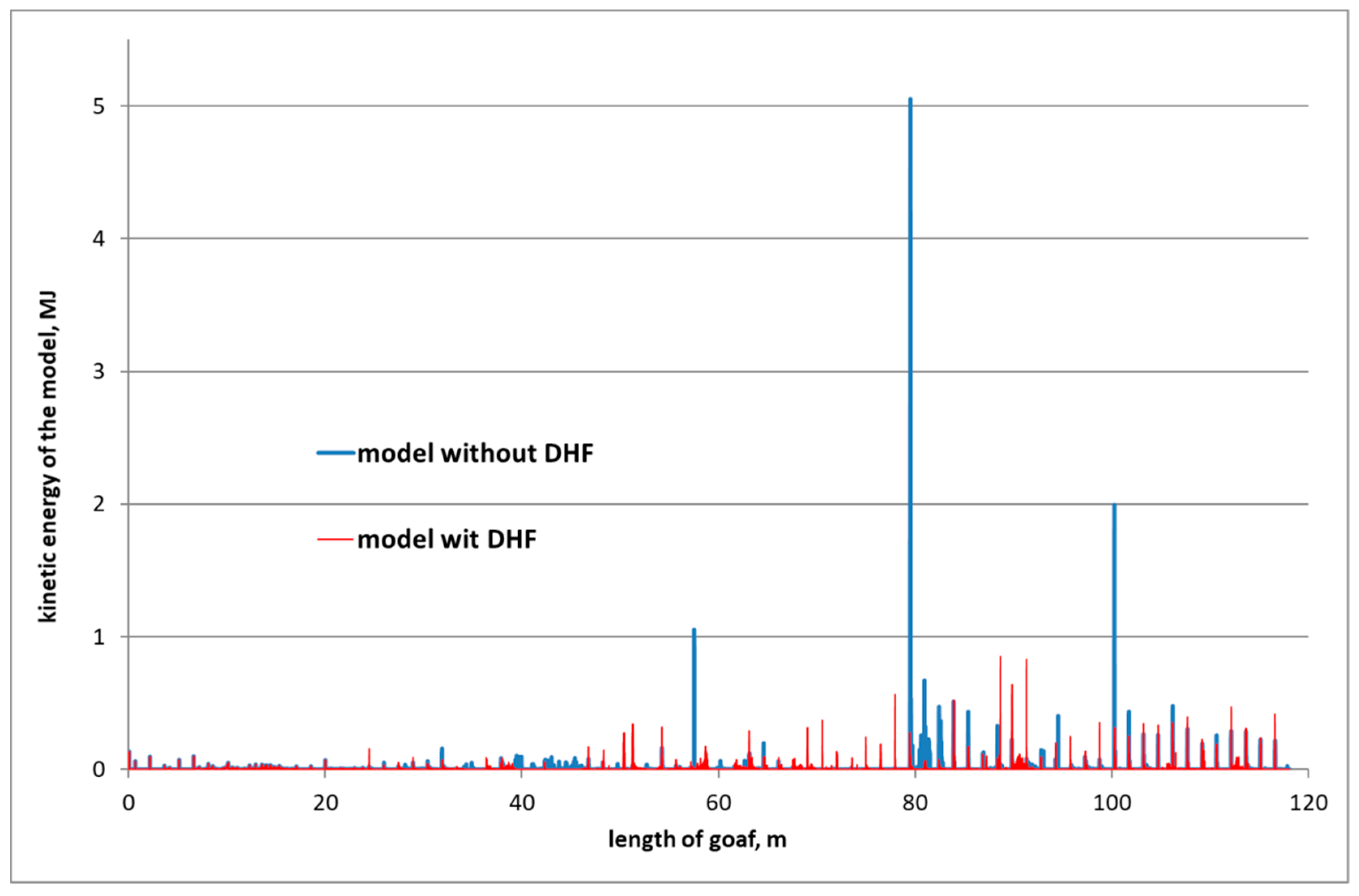
—kinetic energy of all gridpoints
  • m i —mass of grid point i
  • u ˙ i —velocity at grid point i
  • n g p —number of grid points
During the whole simulation of the exploitation of the approximately 120 m long longwall, three happenings took place in the model without the use of hydraulic fracturing, where kinetic energy was generated, equal to over 1∙106 J. Moreover, during the real exploitation of longwall II-E1, along the first 300 m of the panel length, there were three shocks registered with energy exceeding 1∙106 J. The mapping in the DHF model lead to the maximum kinetic energy values not exceeding 1∙106 J.

4. Summary and Conclusions

The results of measurements presented in this article, as well as observations and the authors’ experience, indicate the effectiveness of directional hydraulic fracturing of the roof of exploited coal seam, as a successful method of rock bursts prevention, as well as a method allowing a safe and smooth progress of the longwall with cases of strong layers that go into a collapse with difficulty.
The results of the underground observation were verified by a numerical model based on discrete elements method, which helped to follow and compare the mechanism of the formation of goafs in exploitation carried out with and without the use of directional hydraulic fracturing. The results of the numerical simulations carried out legislated the effectiveness of hydraulic fracturing also within the aspect of kinetic energy generated in the model.
The numerical modeling results demonstrate the mechanism of operation of the discontinuities generated in the roof of the exploited seam with DHF. A cut along the formed fracture is made in front of the wall, which decreases the tension of the floor layer in the coal seam area.
The numerical simulations carried out also show the mechanism of goafs creation when worked with DHF, where the relations between the components are both broken off and cut behind the support line, and the previously created fracture speeds up the degradation process of the roof layer and encourages the formation of a cave immediately behind the support.
The biggest advantage of the simulation is the determination of DHF’s effect on the model’s kinetic energy. Three rock bursts with kinetic energy exceeding 1 MJ were produced in the model without DHF, whereas the kinetic energy consumed did not surpass 1 MJ in the simulation with DHF in mind.
The most important conclusion from this article is the confirmation of the effectiveness of DHF as a method of rock burst prevention. The presented results show that DHF facilitates the longwall advance in the conditions of high-strength roof layers. The results also indicate the possibility of using discontinuous modeling to determine the rock mass state and design the exploitation.

Author Contributions

Conceptualization, M.J.; Methodology, MJ., A.H. and M.Ć.; Software, M.J.; Validation, M.J.; Formal Analysis, M.J and A.H.; Investigation, M.J., A.H. and M.Ć.; Resources, M.J and A.H.; Data Curation, A.H. and M.Ć.; Writing-Original Draft Preparation, M.J, A.H. and M.Ć.; Writing-Review & Editing, M.J.; Visualization, M.J., A.H. and M.Ć.; Supervision, M.J.; Project Administration, M.J.; Funding Acquisition, M.J. All authors have read and agreed to the published version of the manuscript.

Funding

Research subsidy of Faculty of Mining, Safety Engineering and Industrial Automation, Silesian University of Technology.

Institutional Review Board Statement

Not Applicable.

Informed Consent Statement

Not Applicable.

Data Availability Statement

The data presented in this study are available on request from the corresponding author.

Conflicts of Interest

The authors declare no conflict of interest.

References

  1. Montgomery, C.T.; Smith, M.B. Hydraulic Fracturing: History of an Enduring Technology. J. Pet. Technol. 2010, 62, 26–40. [Google Scholar] [CrossRef]
  2. Gandossi, L. An Overview of Hydraulic Fracturing and Other Formation Stimulation Technologies for Shale Gas Production; Scientific and Policy Report by the Joint Research Centre of the European Commission, Publications Office of the European Union: Luxembourg, 2013. [Google Scholar]
  3. Gandossi, L.; Von Estorff, U. An Overview of Hydraulic Fracturing and Other Formation Stimulation Technologies for Shale Gas Production—Update 2015; Science for Policy report by the Joint Research Centre, Joint Research Centre of the European Commission, Technical Report, Publications Office of the European Union: Luxembourg, 2015. [Google Scholar]
  4. Liew, M.S.; Danyaro, K.U.; Zawawi, N.A.W.A. A Comprehensive Guide to Different Fracturing Technologies: A Review. Energies 2020, 13, 3326. [Google Scholar] [CrossRef]
  5. Kabiesz, J.; Lurka, A.; Drzewiecki, J. Selected Methods of Rock Structure Disintegration to Control Mining Hazards Wybrane Metody Dezintegracji Struktury Skał Dla Zwalczania Zagrożeń Górniczych. Arch. Min. Sci. 2015, 60, 807–824. [Google Scholar] [CrossRef] [Green Version]
  6. Liu, J.; Liu, C.; Li, X. Determination of fracture location of double-sided directional fracturing pressure relief for hard roof of large upper goaf-side coal pillars. Energy Explor. Exploit. 2020, 38, 111–136. [Google Scholar] [CrossRef] [Green Version]
  7. Frejowski, A.; Myszkowski, J. Możliwości wykorzystania metody ukierunkowanego hydroszczelinowania skał (UHS) do odmetanowania górotworu karbońskiego w warunkach GZW. Prace Naukowe GIG. Górnictwo i Środowisko 2009, 4, 74–82. [Google Scholar]
  8. Fan, J.; Dou, L.; He, H.; Du, T.; Zhang, S.; Gui, B.; Sun, X. Directional hydraulic fracturing to control hard-roof rockburst in coal mines. Int. J. Min. Sci. Technol. 2012, 22, 177–181. [Google Scholar] [CrossRef]
  9. Haimson, B. Deep in-Situ Stress Measurements by Hydrofracturing. Dev. Geotecton. 1975, 9, 41–47. [Google Scholar]
  10. Cornet, F.H.; Valette, B. In Situ Stress Determination from Hydraulic Injection Test Data. J. Geophys. Res. 1984, 89, 11527–11537. [Google Scholar] [CrossRef]
  11. Makówka, J. Method of Determining the Triaxial Stress State in the Rock Mass with Directed Hydrofracturing/Metoda Określania Trójosiowego Stanu Naprężenia W Górotworze Z Użyciem Ukierunkowanego Hydroszczelinowania. Arch. Min. Sci. 2015, 60, 729–741. [Google Scholar] [CrossRef] [Green Version]
  12. Patyńska, R.; Kabiesz, J. Scale of seismic and rock burst hazard in the Silesian companies in Poland. Min. Sci. Technol. 2009, 19, 604–608. [Google Scholar]
  13. Mutke, G.; Dubiński, J.; Lurka, A. New Criteria to Assess Seismic and Rock Burst Hazard in Coal Mines / Nowe Kryteria Dla Oceny Zagrożenia Sejsmicznego I Tąpaniami W Kopalniach Węgla Kamiennego. Arch. Min. Sci. 2015, 60, 743–760. [Google Scholar] [CrossRef] [Green Version]
  14. Liu, X.; Liu, Q.; Liu, B.; Kang, Y. A Modified Bursting Energy Index for Evaluating Coal Burst Proneness and Its Application in Ordos Coalfield, China. Energies 2020, 13, 1729. [Google Scholar] [CrossRef] [Green Version]
  15. Mark, C. Coal bursts in the deep longwall mines of the United States. Int. J. Coal Sci. Technol. 2016, 3, 1–9. [Google Scholar] [CrossRef] [Green Version]
  16. Dou, L.-M.; Mu, Z.-L.; Li, Z.-L.; Cao, A.-Y.; Gong, S. Research progress of monitoring, forecasting, and prevention of rockburst in underground coal mining in China. Int. J. Coal Sci. Technol. 2014, 1, 278–288. [Google Scholar] [CrossRef] [Green Version]
  17. Keneti, A.; Sainsbury, B.-A.L. Review of published rockburst events and their contributing factors. Eng. Geol. 2018, 246, 361–373. [Google Scholar] [CrossRef]
  18. Li, C.C.; Mikula, P.; Simser, B.; Hebblewhite, B.; Joughin, W.; Feng, X.; Xu, N. Discussions on rockburst and dynamic ground support in deep mines. J. Rock Mech. Geotech. Eng. 2019, 11, 1110–1118. [Google Scholar] [CrossRef]
  19. Konopko, W.; Myszkowski, J. Wyprzedzająca aktywna profilaktyka tąpaniowa. Przegląd Górniczy 2005, 61, 33–38. [Google Scholar]
  20. Myszkowski, J. Metoda ukierunkowanego szczelinowania skał. Część 3, Zasady projektowania ukierunkowanego szczelinowania. Przegląd Górniczy 2007, 63, 21–25. [Google Scholar]
  21. Konopko, W.; Kabiesz, J.; Merta, G.; Makówka, J. Ukierunkowane hydroszczelinowanie skał i kierunki jego wykorzystania. Prace Naukowe Głównego Instytutu Górnictwa 1997, 824, 1–33. [Google Scholar]
  22. Myszkowski, J.; Makówka, J.; Merta, G. Ukierunkowane hydroszczelinowanie skał - nowe rozwiązania i zastosowania. Przegląd Górniczy 2019, 75, 43–50. [Google Scholar]
  23. Konopko, W. Ukierunkowane hydroszczelinowanie skał (UHS). Przegląd Górniczy 1991, 6, 1–8. [Google Scholar]
  24. Tajduś, A.; Cała, M.; Tajduś, K. Seismicity and rock burst hazard assessment in fault zones: A case study. Arch. Min. Sci. 2018, 63, 747–765. [Google Scholar]
  25. He, M.; Zhang, X.; Zhao, S. Directional Destress with Tension Blasting in Coal Mines. Procedia Eng. 2017, 191, 89–97. [Google Scholar] [CrossRef]
  26. Yang, X.; Liu, C.; Ji, Y.; Zhang, X.; Wang, S. Research on Roof Cutting and Pressure Releasing Technology of Directional Fracture Blasting in Dynamic Pressure Roadway. Geotech. Geol. Eng. 2018, 37, 1555–1567. [Google Scholar] [CrossRef]
  27. Myszkowski, J. Metoda ukierunkowanego szczelinowania skał. Część 1, Istota metody i badania laboratoryjne jej skuteczności. Przegląd Górniczy 2007, 63, 11–16. [Google Scholar]
  28. Deng, J.; Lin, C.; Yang, Q.; Liu, Y.; Tao, Z.; Duan, H. Investigation of directional hydraulic fracturing based on true tri-axial experiment and finite element modeling. Comput. Geotech. 2016, 75, 28–47. [Google Scholar] [CrossRef]
  29. Dubiński, J.; Konopko, W. Tąpania, ocena, prognoza, zwalczanie, 1st ed.; Główny Instytut Górnictwa: Katowice, Poland, 2000; pp. 345–350. [Google Scholar]
  30. He, H.; Dou, L.; Fan, J.; Du, T.; Sun, X. Deep-hole directional fracturing of thick hard roof for rockburst prevention. Tunn. Undergr. Space Technol. 2012, 32, 34–43. [Google Scholar] [CrossRef]
  31. Huang, B.; Liu, J.; Zhang, Q. The reasonable breaking location of overhanging hard roof for directional hydraulic fracturing to control strong strata behaviors of gob-side entry. Int. J. Rock Mech. Min. Sci. 2018, 103, 1–11. [Google Scholar] [CrossRef]
  32. Huang, B.; Zhao, X.; Ma, J.; Sun, T. Field Experiment of Destress Hydraulic Fracturing for Controlling the Large Deformation of the Dynamic Pressure Entry Heading Adjacent to the Advancing Longwall Face. Arch. Min. Sci. 2019, 64, 829–848. [Google Scholar]
  33. UDEC—Universal Distinct Element Code, Version 4.0. User’s Manual, 2nd ed.; Itasca Consulting Group, Inc.: Minneapolis, MI, USA, 2005.
  34. Majchrczyk, T.; Niedbalski, Z.; Małkowski, P. Wzmacnianie obudowy wyrobisk korytarzowych w złożonych warunkach górniczo-geologicznych. Górnictwo i Geoinżynieria 2010, 34, 451–462. [Google Scholar]
  35. Sun, Y.; Li, G.; Zhang, J.; Xu, J. Failure Mechanisms of Rheological Coal Roadway. Sustainability 2020, 12, 2885. [Google Scholar] [CrossRef] [Green Version]
  36. Wesołowski, M. Numerical Modeling of Exploitation Relics and Faults Influence on Rock Mass Deformations. Arch. Min. Sci. 2016, 61, 893–906. [Google Scholar] [CrossRef] [Green Version]
  37. Wang, J.; Qiu, P.; Ning, J.; Zhuang, L.; Yang, S. A numerical study of the mining-induced energy redistribution in a coal seam adjacent to an extracted coal panel during longwall face mining: A case study. Energy Sci. Eng. 2019, 8, 817–835. [Google Scholar] [CrossRef] [Green Version]
  38. Yasitli, N.E.; Unver, B. 3D numerical modeling of longwall mining with top-coal caving. Int. J. Rock Mech. Min. Sci. 2005, 42, 219–235. [Google Scholar] [CrossRef]
  39. Das, R.; Singh, P.K.; Kainthola, A.; Panthee, S.; Singh, T.N. Numerical analysis of surface subsidence in asymmetric parallel highway tunnels. J. Rock Mech. Geotech. Eng. 2017, 9, 170–179. [Google Scholar] [CrossRef]
  40. Kwaśniewski, M. Numerical analysis of strata behavior in the vicinity of a longwall panel in a coal seam mined with roof caving. In Continuum and Distinct Element Numerical Modeling in Geo-Engineering, Proceedings of 1st International FLAC/DEM Symposium, Minneapolis, MI, USA, August 2008; Hart, R.D., Detournay, C., Cundall, P., Eds.; Itasca Consulting Group Inc.: Minneapolis, MI, USA, 2008; paper no. 07-08; pp. 1–8. [Google Scholar]
  41. Gao, F.; Stead, D.; Coggan, J. Evaluation of coal longwall caving characteristics using an innovative UDEC Trigon approach. Comput. Geotech. 2014, 55, 448–460. [Google Scholar] [CrossRef] [Green Version]
  42. Le, T.D.; Oh, J.; Hebblewhite, B.; Zhang, C.; Mitra, R. A discontinuum modelling approach for investigation of Longwall Top Coal Caving mechanisms. Int. J. Rock Mech. Min. Sci. 2018, 106, 84–95. [Google Scholar] [CrossRef]
  43. Cao, J.; Dou, L.; Zhu, G.; He, J.; Wang, S.; Zhou, K. Mechanisms of Rock Burst in Horizontal Section Mining of a Steeply Inclined Extra-Thick Coal Seam and Prevention Technology. Energies 2020, 13, 6043. [Google Scholar] [CrossRef]
  44. Makówka, J. Analiza numeryczna przestrzennego rozkładu stanu naprężenia w otoczeniu typowych układów krawędzi eksploatacji zawałowej za pomocą metody elementów odrębnych. Przegląd Górniczy 2010, 6, 165–179. [Google Scholar]
  45. Politechnika Śląska, B.J.; Mielimąka, R.; Sokoła-Szewioła, V.; Wesołowski, M. Metoda numerycznego modelowania wpływu kolejności i kierunku eksploatacji na deformacje terenu górniczego, 1st ed.; Publishing House of the Silesian University of Technology: Gliwice, Poland, 2015; Volume 1, pp. 46–74. [Google Scholar]
  46. Vakili, A.; Hebblewhite, B.K. A new cavability assessment criterion for Longwall Top Coal Caving. Int. J. Rock Mech. Min. Sci. 2010, 47, 1317–1329. [Google Scholar] [CrossRef]
Figure 1. Map of coal seam 713/1-2 with signified region of hydraulic fracturing in longwall II-E1.
Energies 14 00562 g001
Figure 2. The placement of seismic activities during the exploitation of coal seam 713/1-2 at longwall II-E1 until July 9th 2017 (the first hydraulic fracturing date).
Energies 14 00562 g002
Figure 3. Directional hydraulic fracturing scheme within longwall II-E1 at coal seam 713/1-2.
Energies 14 00562 g003
Figure 4. The placement of seismic activities during the exploitation of coal seam 713/1-2 at longwall II-E1 during the period of DHF performance from July 9th until November 19, 2017.
Energies 14 00562 g004
Figure 5. Rock mass model with the system of discontinuities.
Energies 14 00562 g005
Figure 6. The state of the model during the stage representing the execution of the longwall cross-cut.
Energies 14 00562 g006
Figure 7. The state of the model within the first stages of the simulated exploitation.
Energies 14 00562 g007
Figure 8. The state of the modeled rock mass at chosen stages of the simulation: (a) variants with DHF, (b) variants without DHF.
Energies 14 00562 g008
Figure 9. The formation of goafs in the model including hydraulic fracturing.
Energies 14 00562 g009
Figure 10. Kinetic energy registered in the modeled rock mass.
Energies 14 00562 g010
Table 1. Shocks registered during the exploitation of seam 713/1-2 at longwall I-E1.
MonthMonthly Progress, mLength Left, mNumber of Shocks of Energy:Monthly Summary Energy, JI = E/W, J/tE Max, JE/Progress, J/m
102 J103 J104 J105 J106 J107 J108 JTotal
II10.3578000000000.0 × 1000.00.0 × 1000.0 × 100
III92.3568100000016.3 × 1020.06.3 × 1026.8 × 100
IV78.3492401000051.8 × 1040.51.5 × 1042.3 × 102
V51.3438010000011.3 × 1030.01.3 × 1032.5 × 101
VI58.5383521100092.5 × 1056.01.6 × 1054.3 × 103
VII104.32797510200153.2 × 10645.21.9 × 1063.1 × 104
VIII71.0210132840000451.5 × 1053.33.1 × 1042.1 × 103
IX74.513681620010272.0 × 107399.32.0 × 1072.7 × 105
X92.044051100074.2 × 1057.83.1 × 1054.6 × 103
XI43.01100100022.9 × 1050.02.9 × 1056.7 × 103
Total:39571032101122.4 × 107-2.0 × 10⁷-
Table 2. Shocks registered during the exploitation of seam 713/1-2 at longwall II-E1 until July 9th 2017 (until the first hydraulic fracturing).
MonthMonthly Progress, mLength Left, mNumber of Shocks of Energy:Monthly Summary Energy, JI = E/W, J/tE Max, JE/Progress, J/m
102 J103 J104 J105 J106 J107 J108 JTotal
III16.3646100000016.7 × 1020.16.7 × 1024.1 × 101
IV93.55523901000132.6 × 1054.88.5 × 1032.8 × 103
V123.04294223100200776.8 × 10671.93.4 × 1065.5 × 104
VI111.83182832240500892.0 × 107279.37.9 × 1061.8 × 105
VII58.5259131090000324.3 × 10523.39.0 × 1041.5 × 104
Total:87744317002122.7 × 107-1.2 × 10⁷-
Table 3. Shocks registered during the exploitation of coal seam 713/1-2 at longwall II-E1 during the performance of DHF from July 9th until November 19, 2017.
MonthMonthly Progress, mLength Left, mNumber of Shocks of Energy:Monthly Summary Energy, JI = E/W, J/tE Max, JE/Progress, J/m
102 J103 J104 J105 J106 J107 J108 JTotal
VII58.52592629110000668.6 × 10523.39.0 × 1041.5 × 104
VIII7018951501731001224.2 × 10672.13.3 × 1056.0 × 104
IX7611368981300001796.6 × 10515.03.3 × 1048.7 × 103
X73.2539.7530691400001134.9 × 10512.06.2 × 1046.7 × 103
XI40−0.25162011000388.9 × 10531.13.1 × 1052.2 × 104
Total:1912665641005187.10 × 106-1.2 × 10⁷-
Publisher’s Note: MDPI stays neutral with regard to jurisdictional claims in published maps and institutional affiliations.

