The Use of Capsuled Paraffin Wax in Low-Temperature Thermal Energy Storage Applications: An Experimental and Numerical Investigation


Abstract
1. Introduction
2. Phase Change Material (PCM)
2.1. General Description of the PCM
2.2. Analysis of the PCM’s Internal Structure
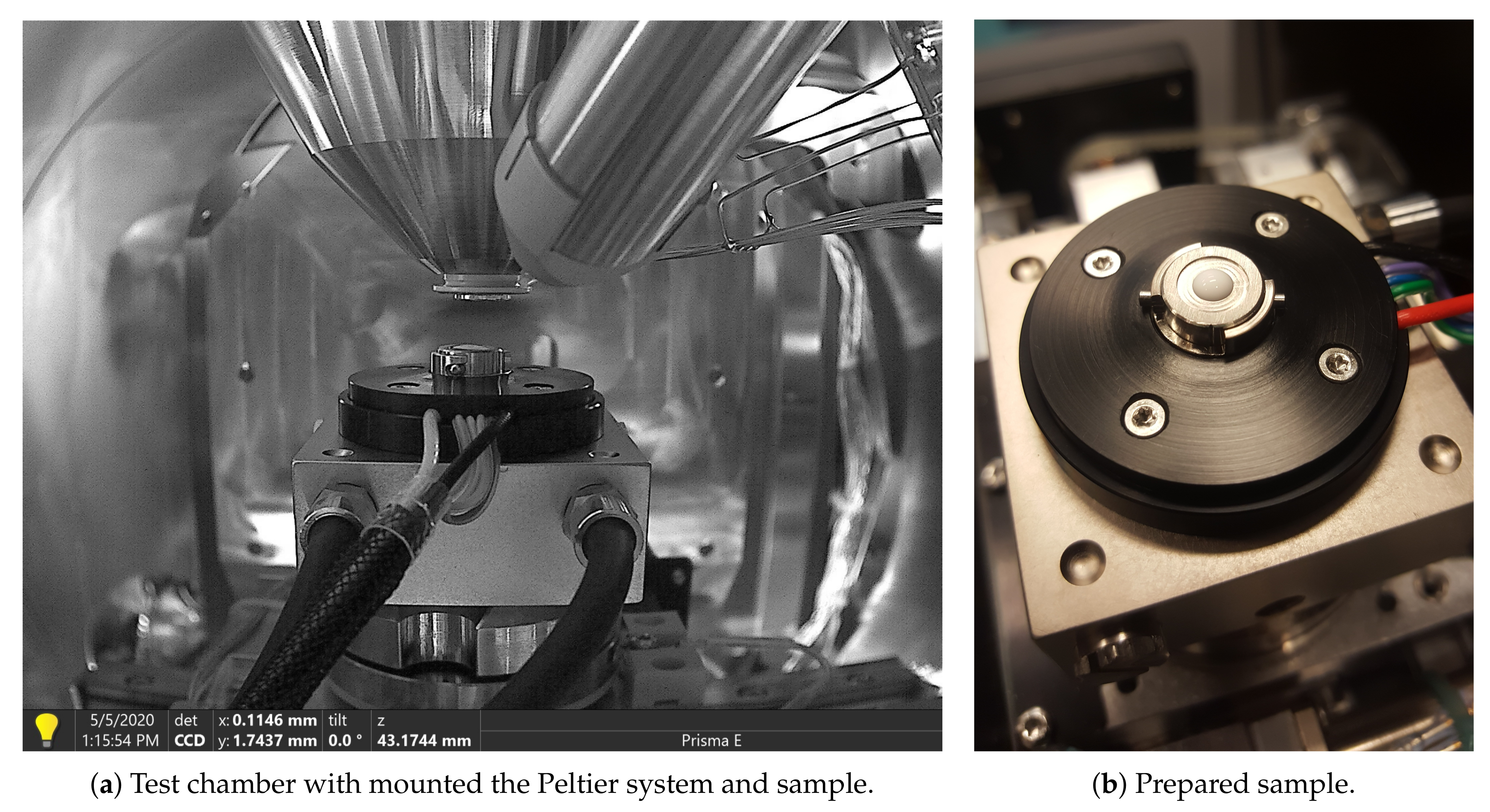
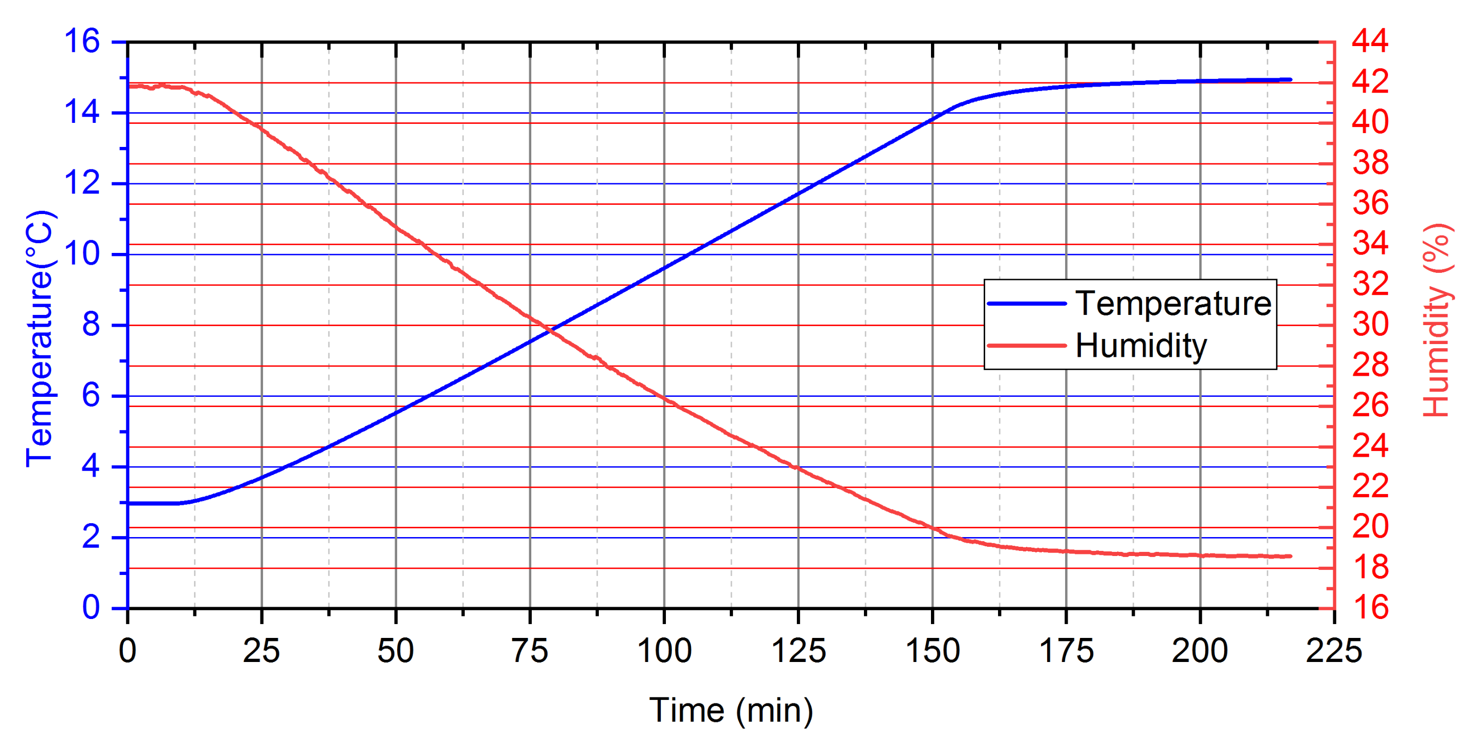
2.2.1. Test Conditions and Testing Procedures
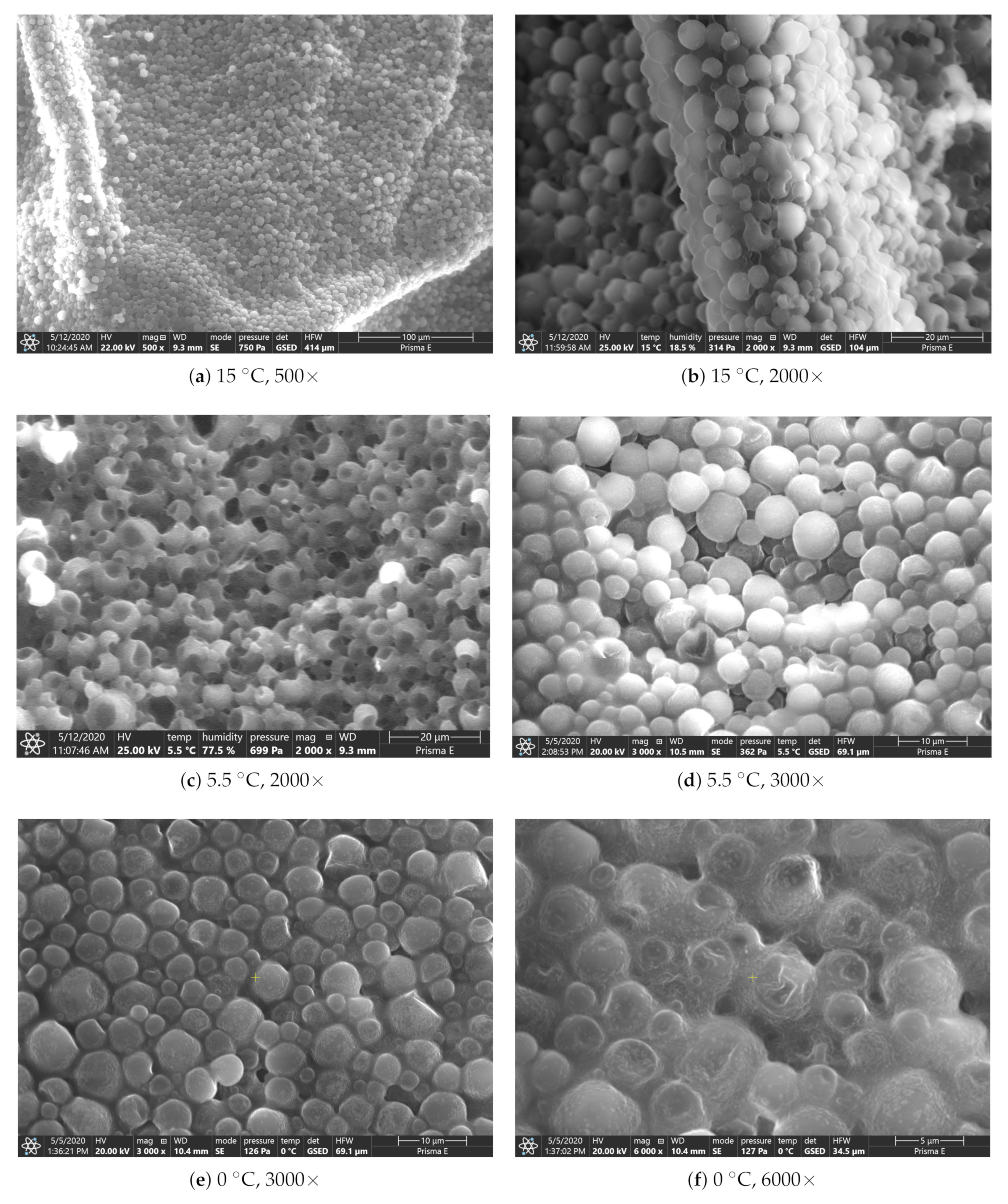
2.2.2. SEM Analysing
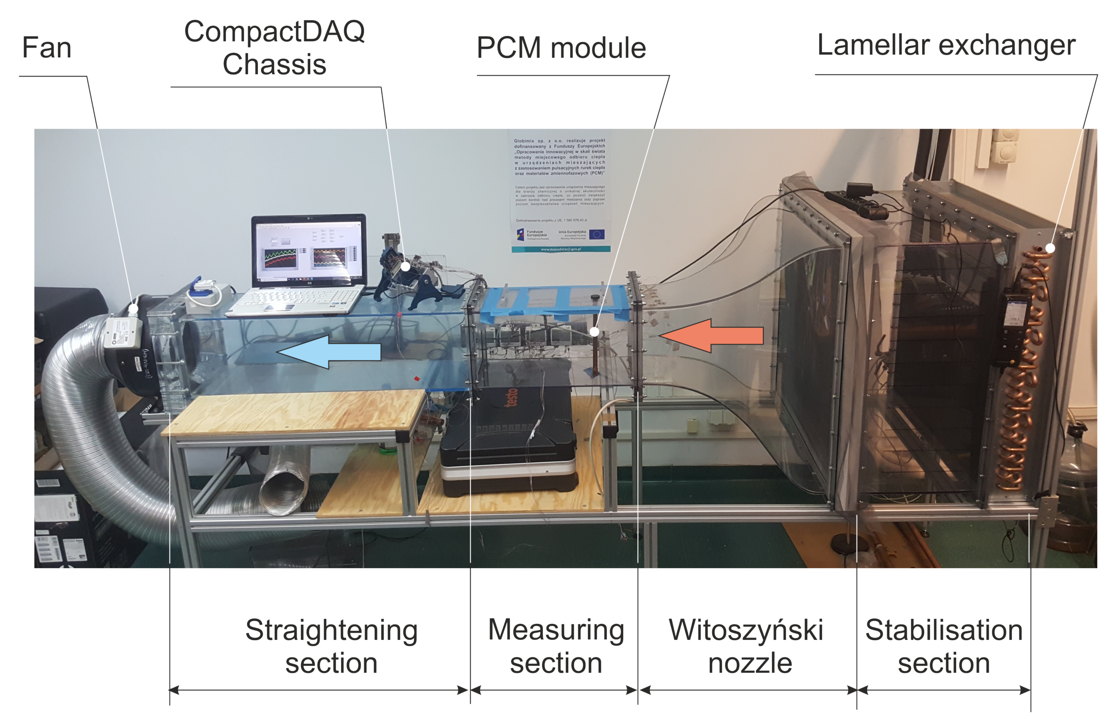
3. Experimental Set-Up and Measuring Procedure
3.1. General Description
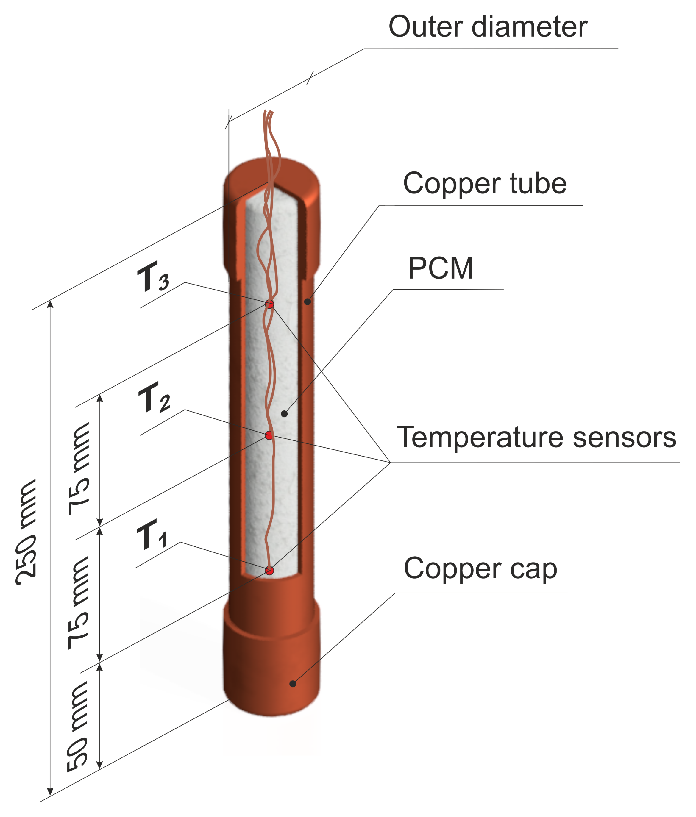
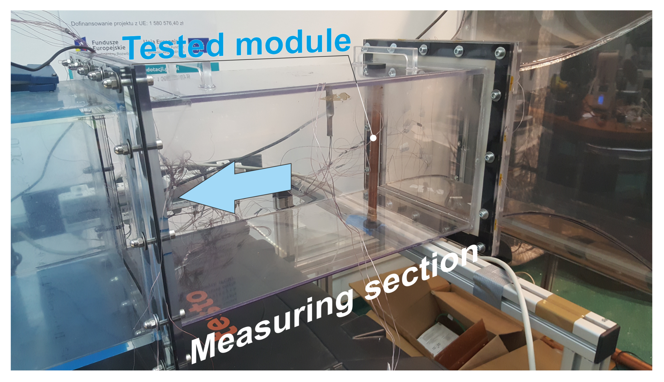
3.2. Tested Module
3.3. Preparation of the Module to the Test
3.4. Measurement and Control Systems
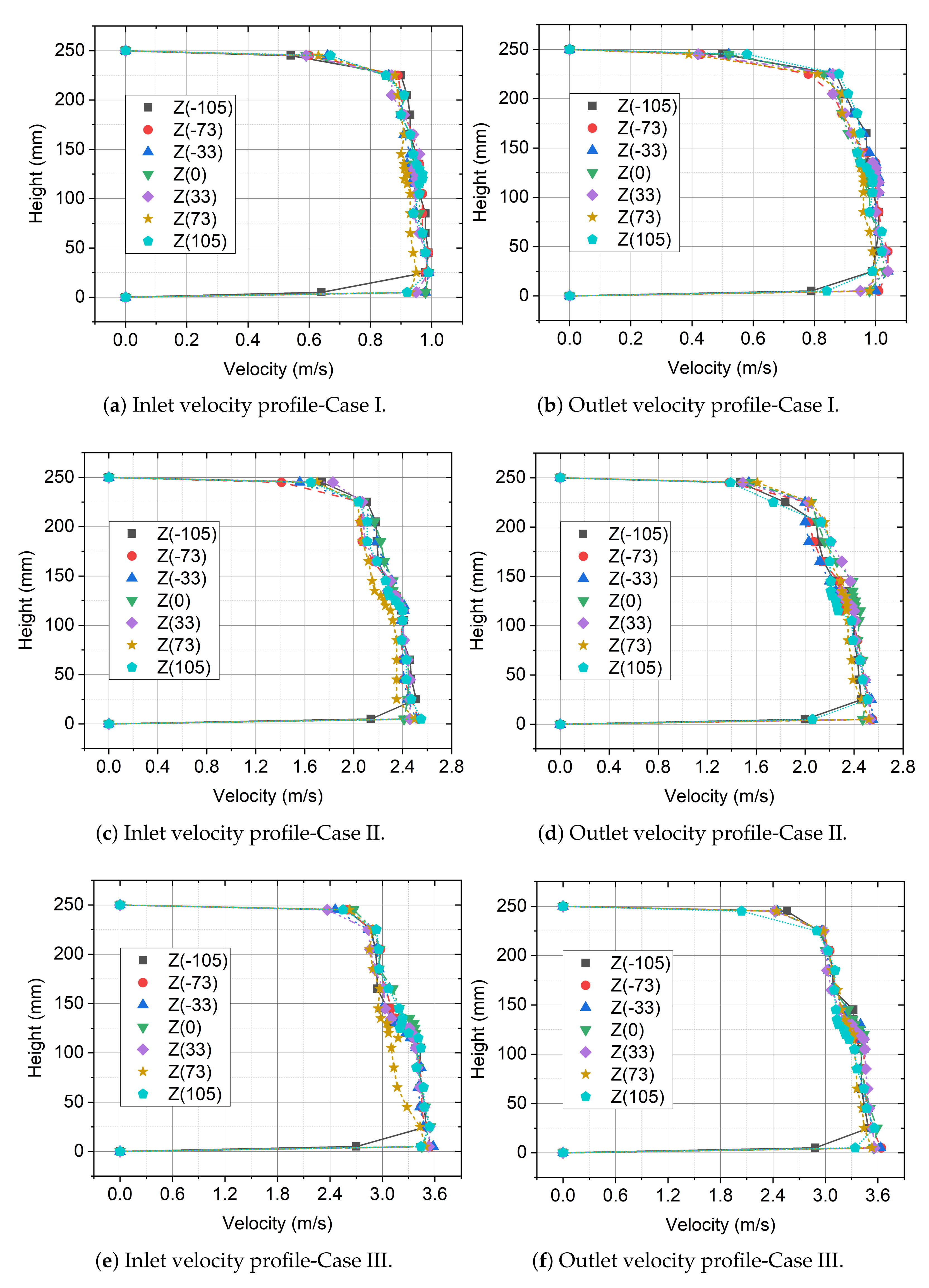
3.5. Velocity Profiles at the Inlet and Outlet of the Measurement Section
4. Numerical Modeling of the Analyzed System with PCM
4.1. Process Governing Equations
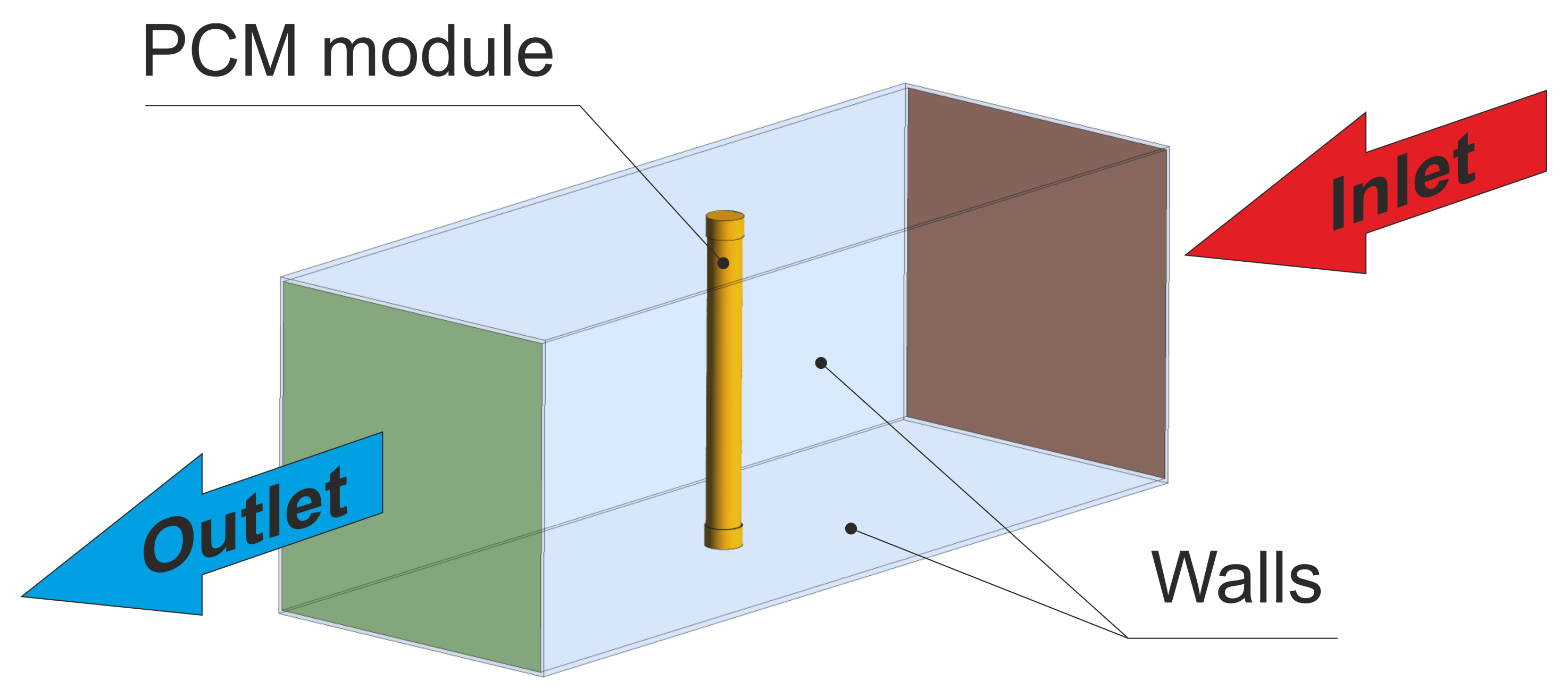
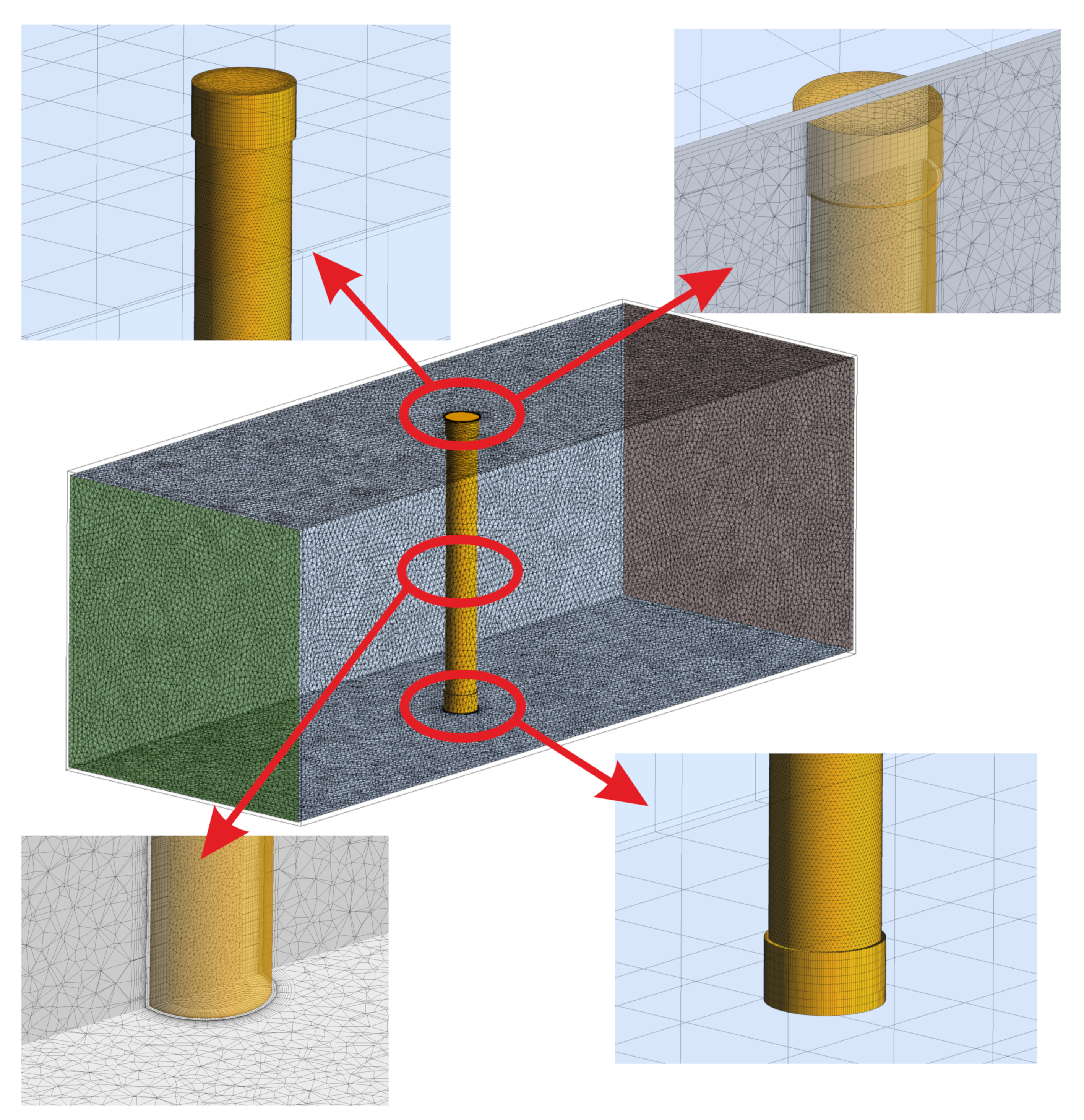
4.2. Geometry, Boundary and Initial Conditions and Numerical Schemes
5. Results
5.1. Experimental Results
5.2. Numerical Results
6. Conclusions
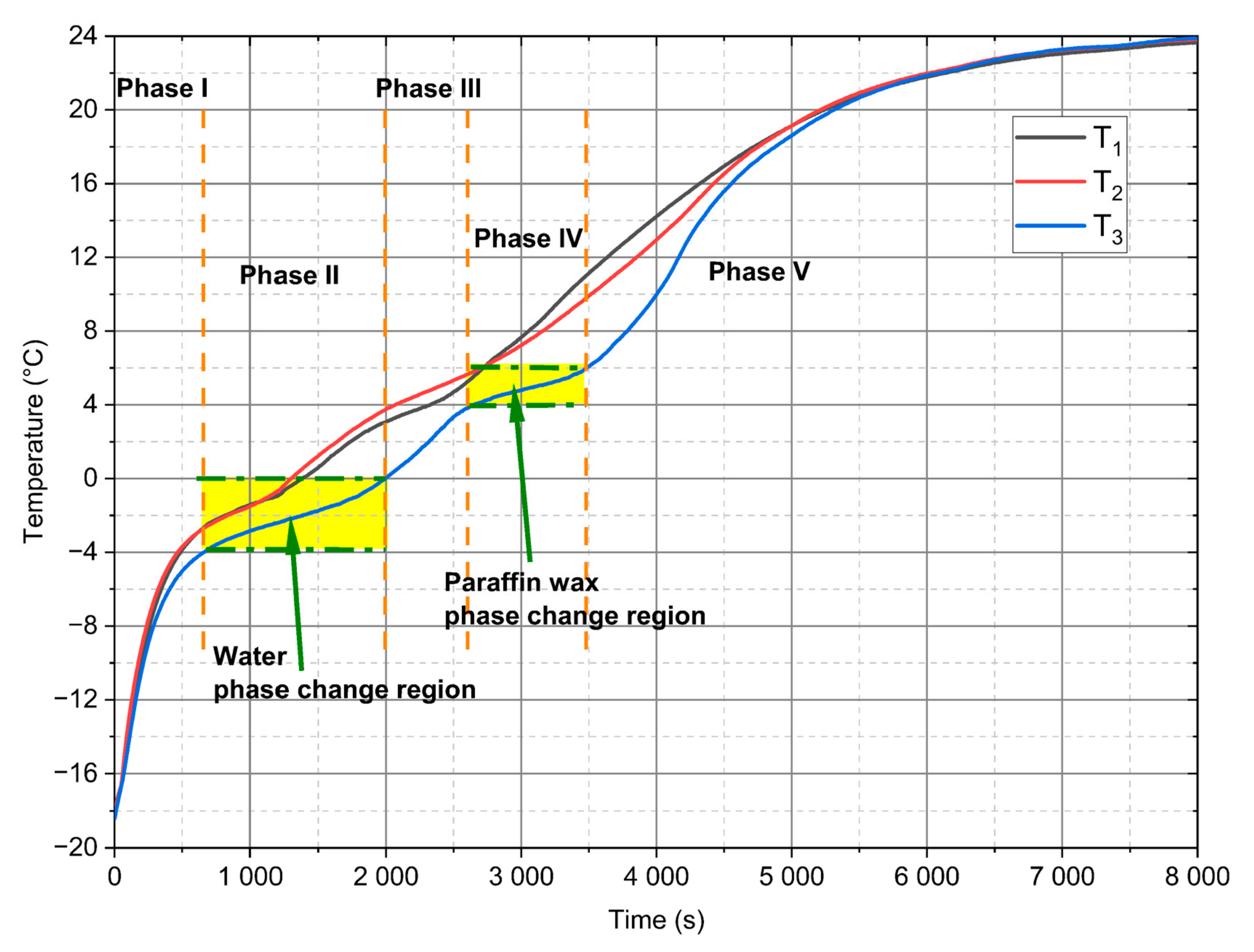
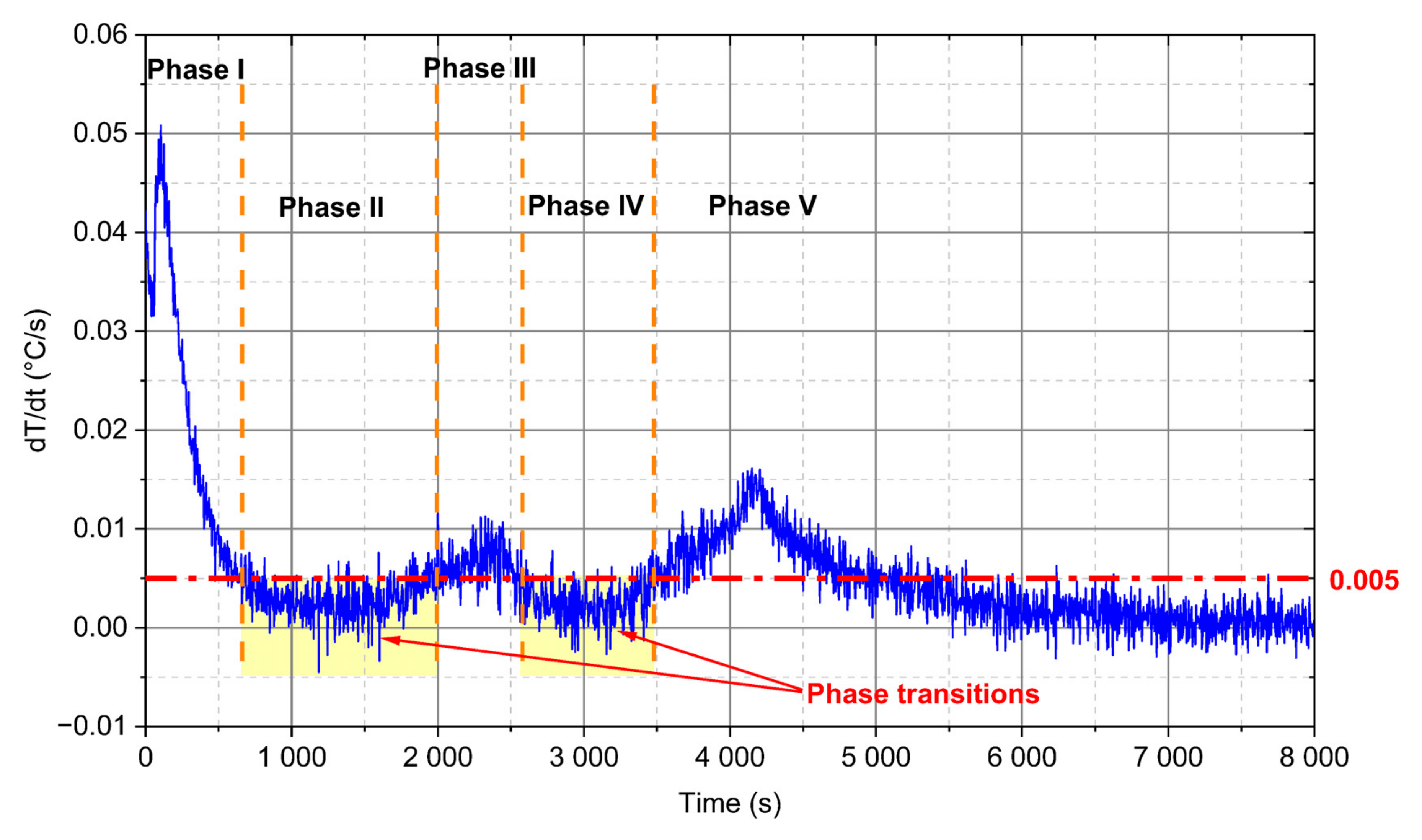
- For analysed PCM, five distinct phases during the heating process can be observed (Figure 10). Two of these phases are a phenomenon, in which phase change processes can be singled out. The first transformation is characteristic for water in the temperature range from −4 °C to 0 °C and the second is identified for paraffin from 4 °C to 6 °C.
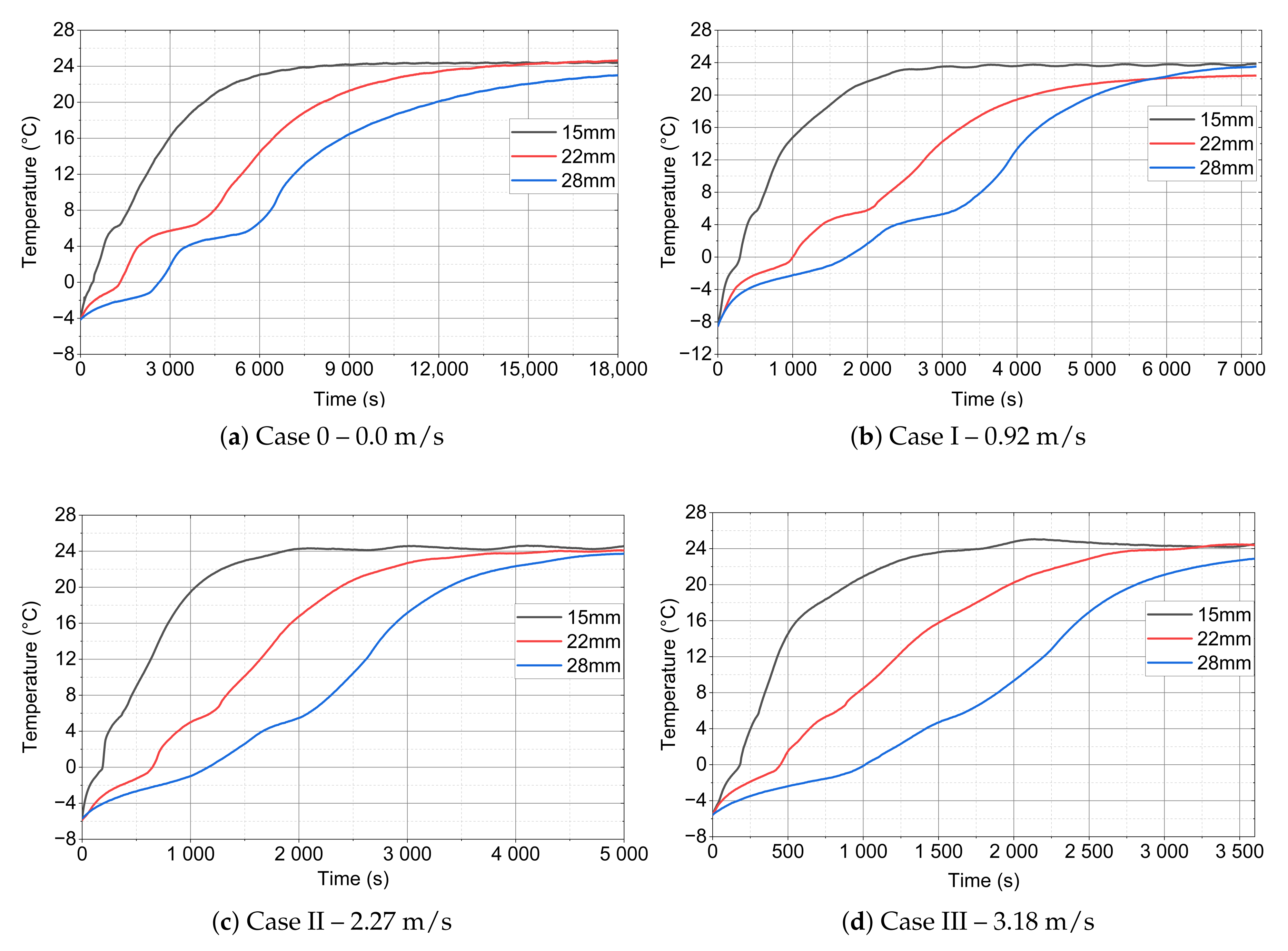
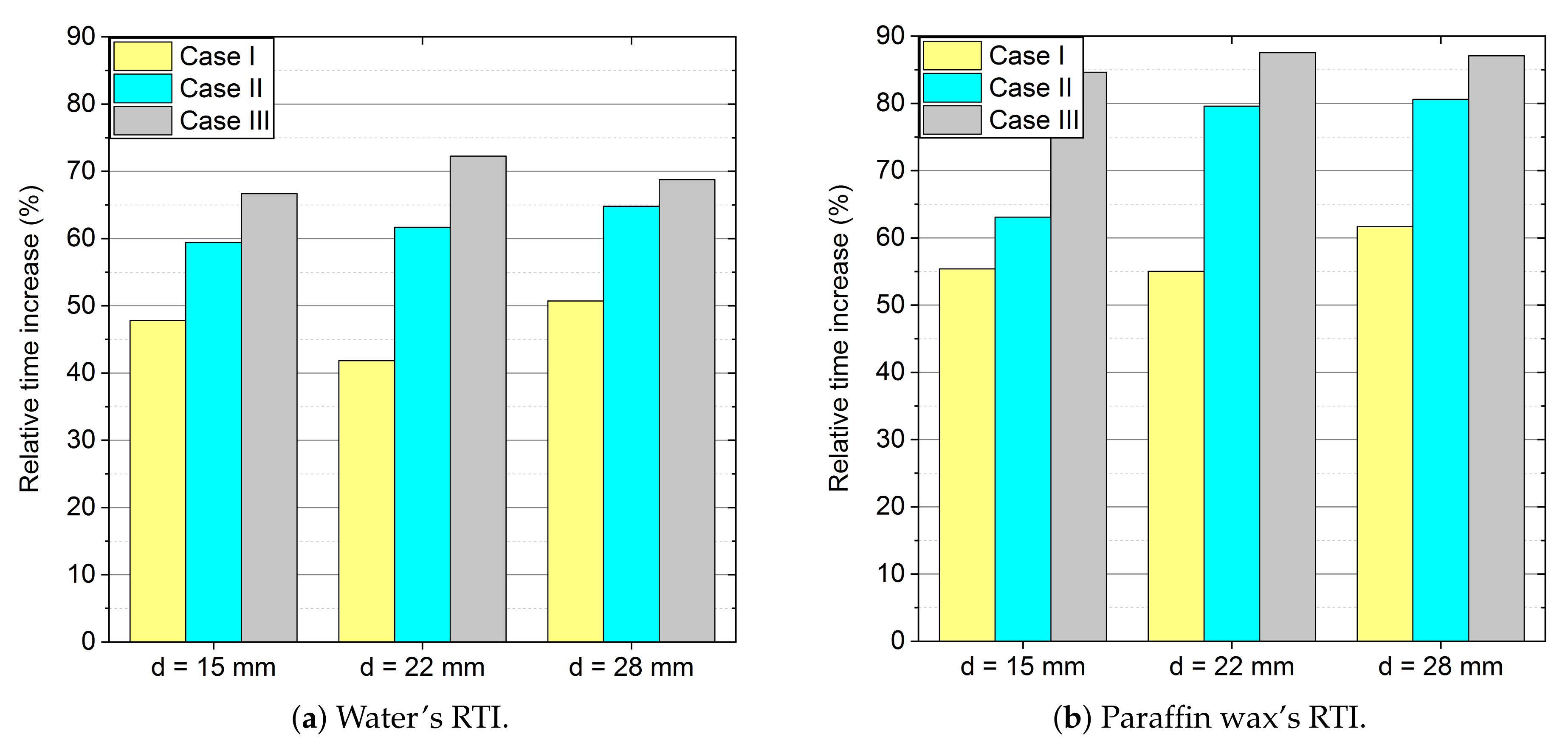
- Because of the use of forced convection, the time of the melting process can be reduced by even up to 87% (RTI) as compared to stagnation conditions, as shown in Table 6 and Table 7 and Figure 13. It is also worth emphasising that, when changing the outer diameter from the module from 22 to 28 mm, these changes are less noticeable than for the diameters of 18 to 22 mm.
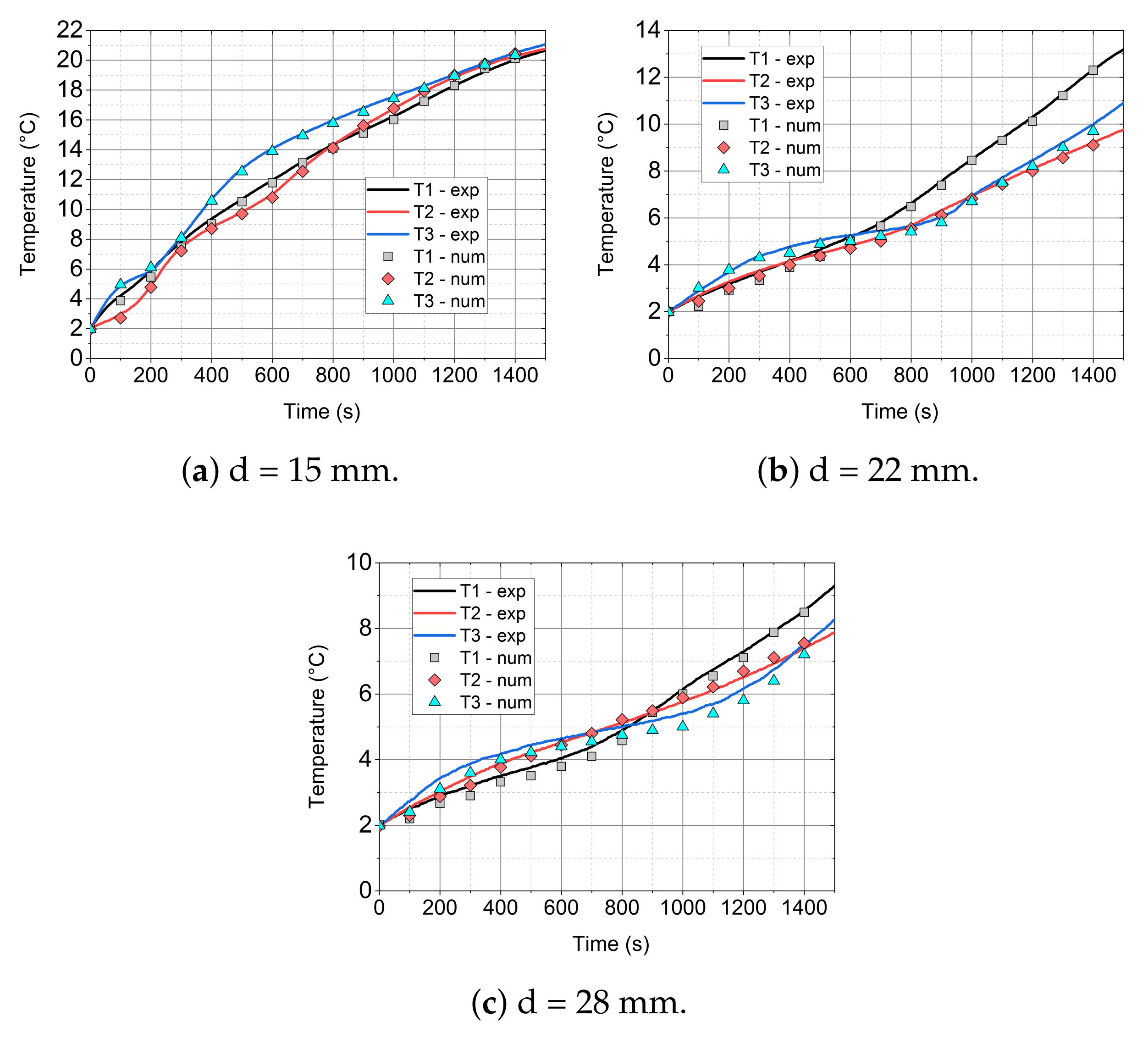
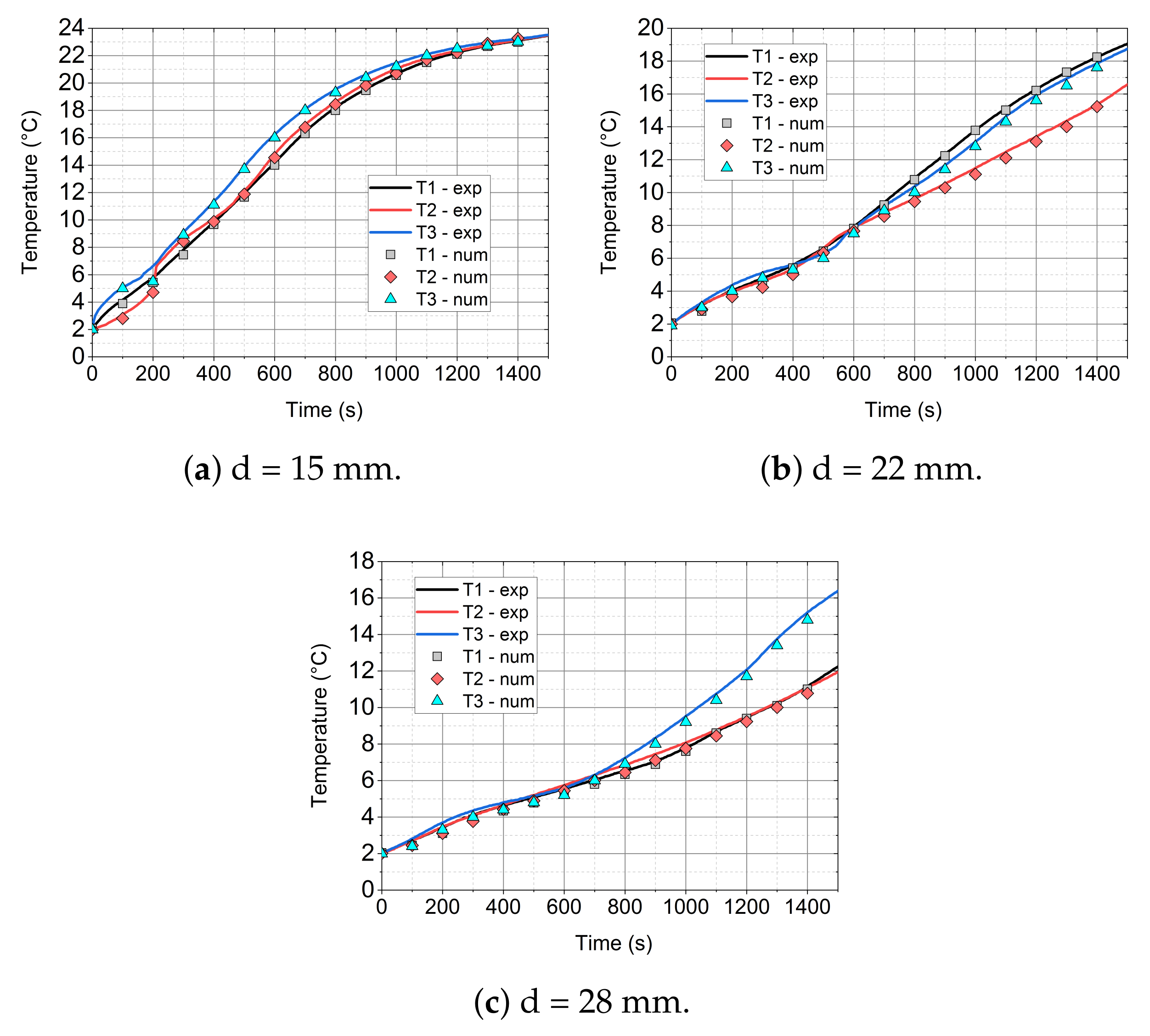
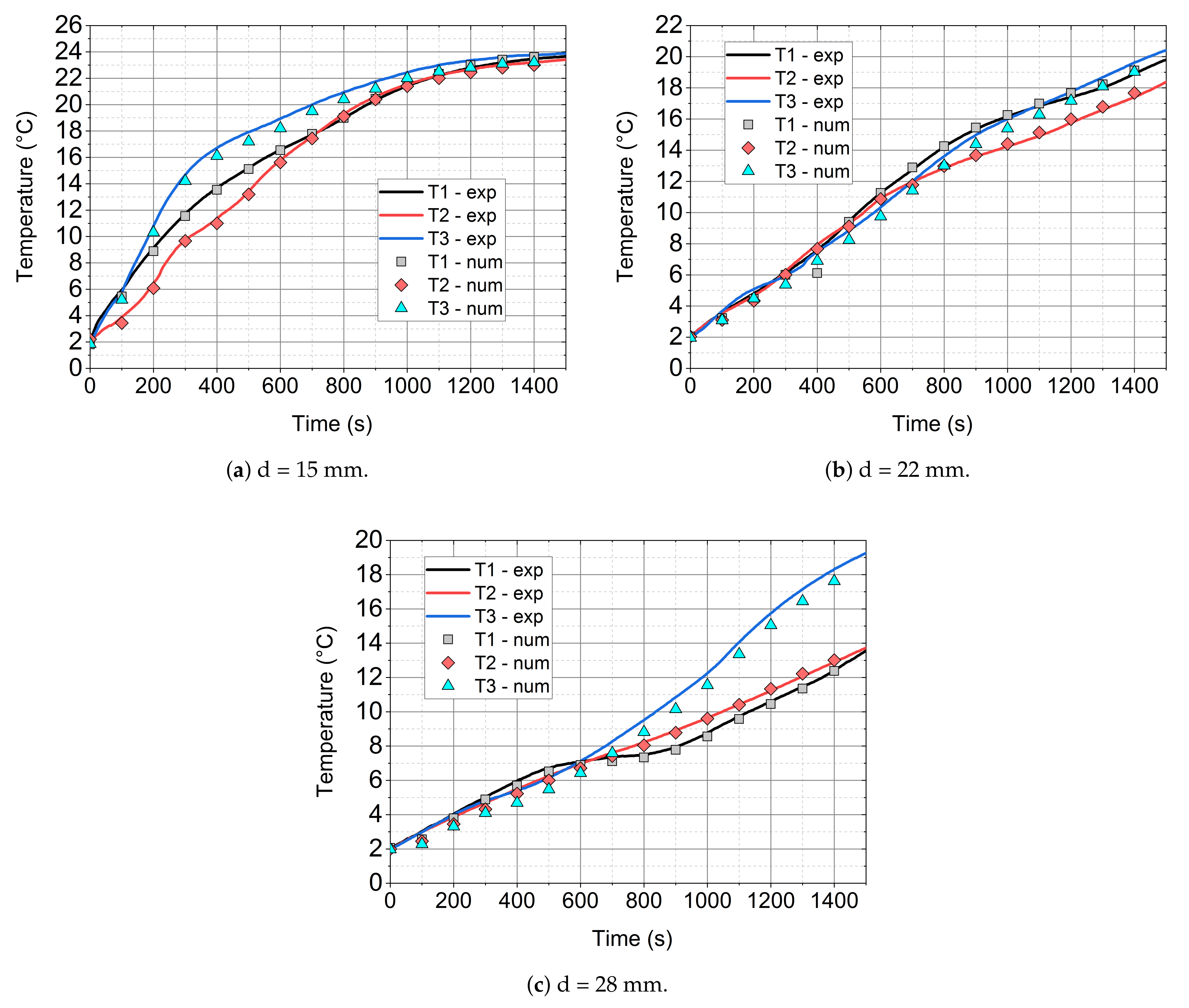
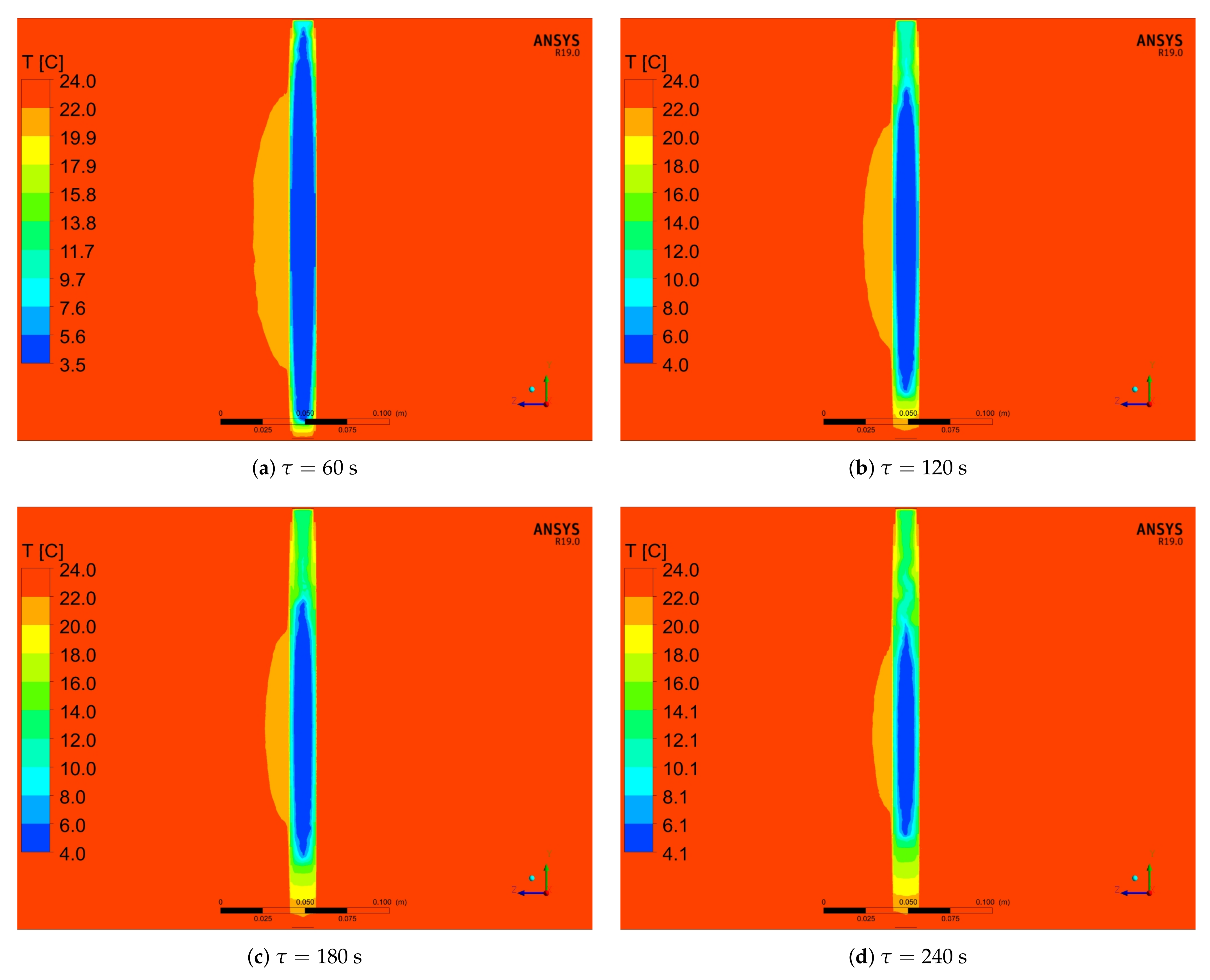
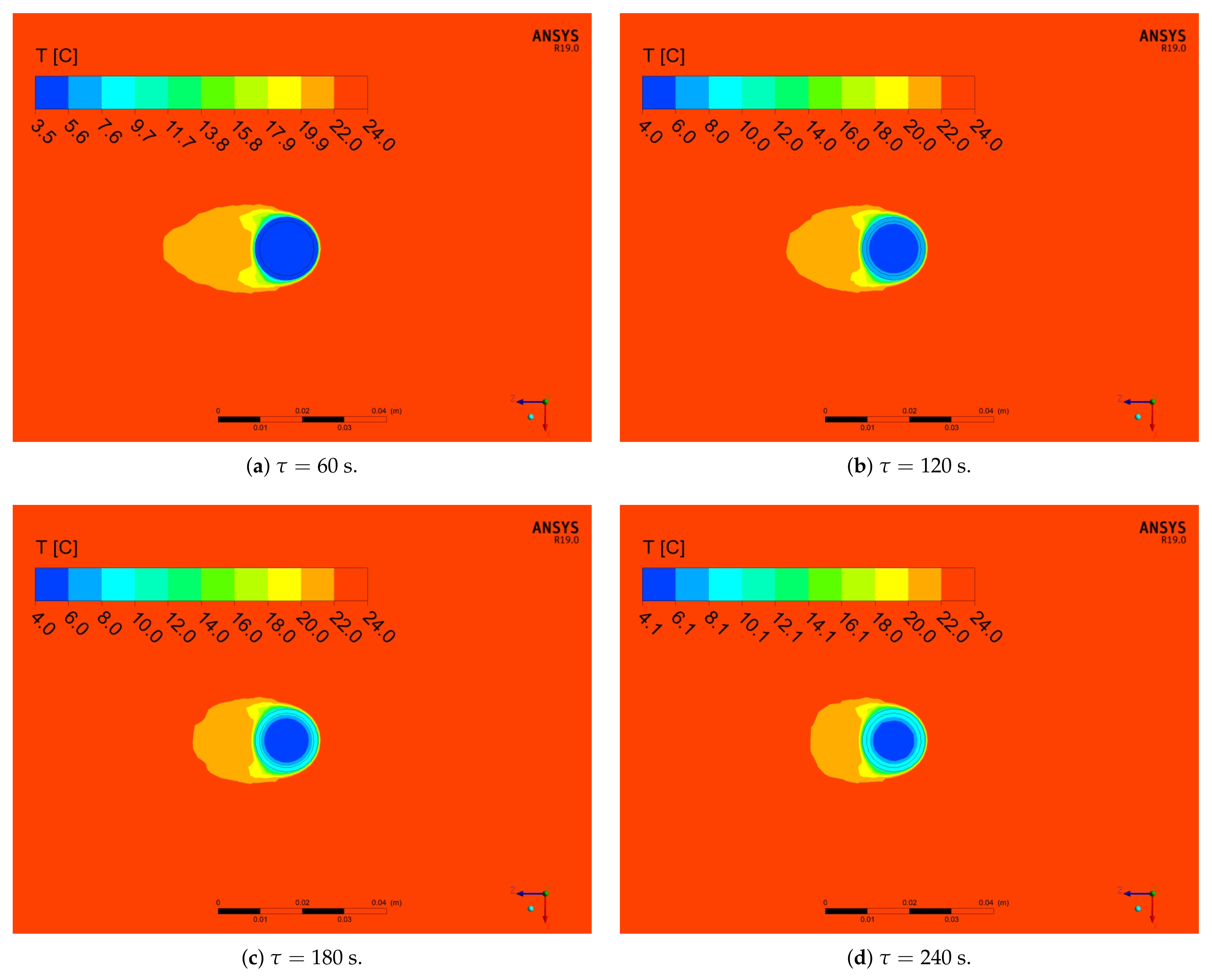
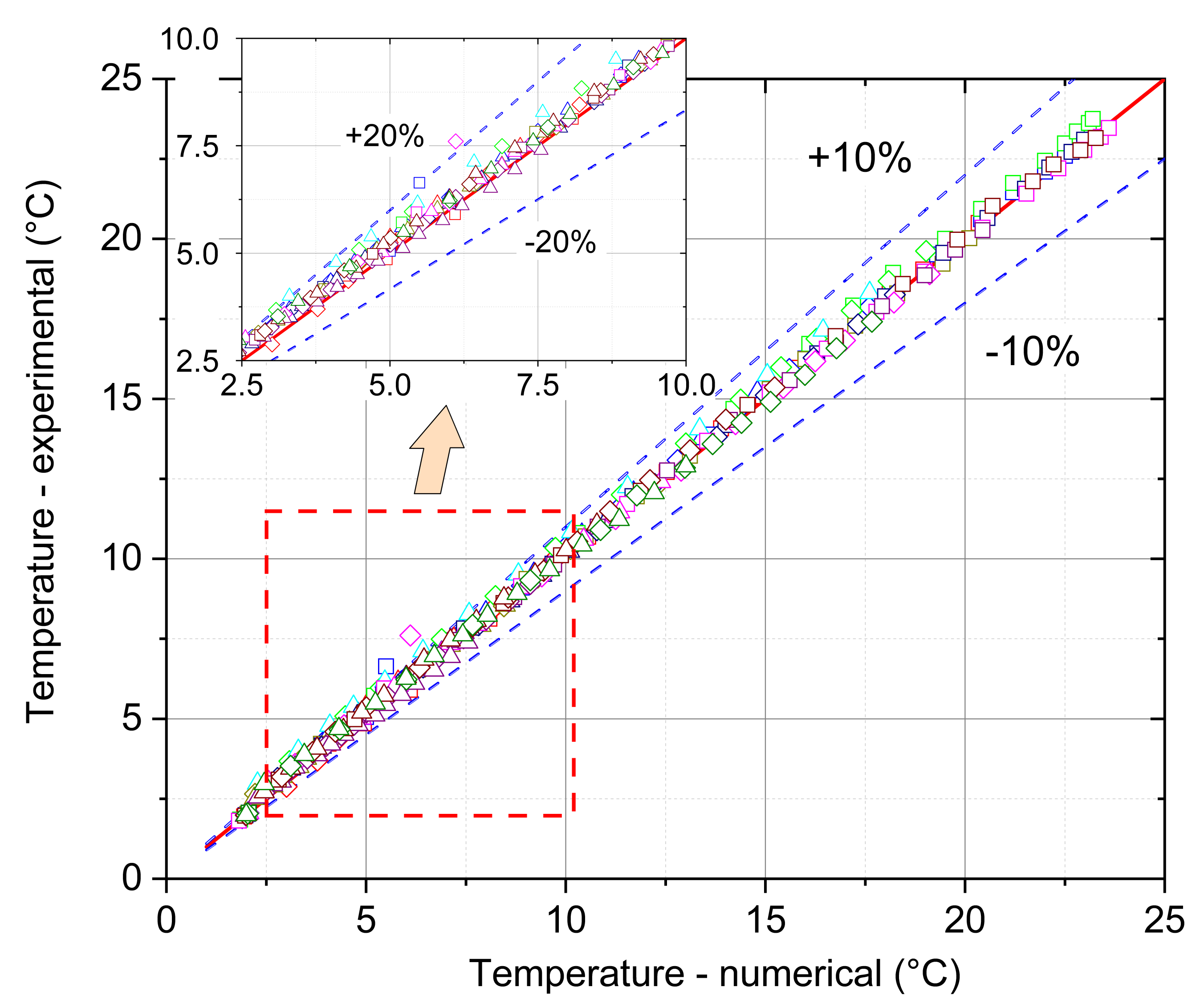
- The mathematical model that is based on the enthalpy porosity method (Equations (1)–(4)) reproduces the conditions in the phase change material during the heating process with a maximum error of up to 20%. (Figure 14, Figure 15 and Figure 16 and Figure 19). It is very important that the proposed model should be implemented in the numerical code, together with variable thermophysical properties (Equations (5)–(7)).
- The SEM tests confirmed the homogeneous structure of the mixture and the lack of changes in the internal structure during phase transformations at characteristic temperatures (Figure 3).
Author Contributions
Funding
Institutional Review Board Statement
Informed Consent Statement
Acknowledgments
Conflicts of Interest
Abbreviations
| CFD | Computational Fluid Dynamics |
| FSOHP | Flower Shape Oscillating Heat Pipe |
| FVM | Finite Volume Method |
| LHTES | Latent Heat Thermal Energy Storage |
| PCM | Phase Change Material |
| PDE | Partial Differential Equation |
| RTI | Relative Time Increase |
| SEM | Scanning Electron Microscope |
| TES | Thermal Energy Storage |
References
- Edenhofer, O.; Pichs-Madruga, R.; Sokona, Y.; Seyboth, K.; Kadner, S.; Zwickel, T.; Eickemeier, P.; Hansen, G.; Schlömer, S.; von Stechow, C.; et al. Renewable Energy Sources and Climate Change Mitigation: Special Report of the Intergovernmental Panel on Climate Change; Cambridge University Press: Cambridge, UK, 2011. [Google Scholar]
- Paksoy, H.Ö. Thermal Energy Storage for Sustainable Energy Consumption, Fundamentals, Case Studies and Design; Springer: Dordrecht, The Netherlands, 2007. [Google Scholar]
- Zalba, B.; Marín, B.; Cabeza, J.; Mehling, H. Review on thermal energy storage with phase change: Materials, heat transfer analysis and applications. Appl. Therm. Eng. 2003, 23, 251–283. [Google Scholar] [CrossRef]
- Jiji, L.M.; Gaye, S. Analysis of solidification and melting of PCM with energy generation. Appl. Therm. Eng. 2006, 26, 568–575. [Google Scholar] [CrossRef]
- An, C.; Su, J. Lumped parameter model for one-dimensional melting in a slab with volumetric heat generation. Appl. Therm. Eng. 2013, 60, 387–396. [Google Scholar] [CrossRef]
- Kalaiselvam, S.; Veerappan, M.; Arul Aaron, A.; Iniyan, S. Experimental and analytical investigation of solidification and melting characteristics of PCMs inside cylindrical encapsulation. Int. J. Therm. Sci. 2008, 47, 858–874. [Google Scholar] [CrossRef]
- Cheng, R.; Wang, X.; Zhang, Y.P. Energy-Efficient Building Envelopes with Phase-Change Materials: New Understanding and Related Research. Heat Transf. Eng. 2014, 35, 970–984. [Google Scholar] [CrossRef]
- Shi, X.; Memon, S.A.; Tang, W.C.; Cui, H.Z.; Xing, F. Experimental assessment of position of macro encapsulated phase change material in concrete walls on indoor temperatures and humidity levels. Energy Build. 2014, 71, 80–87. [Google Scholar] [CrossRef]
- Qu, M.L.; Xia, L.; Deng, S.M.; Jiang, Y.Q. Improved indoor thermal comfort during defrost with a novel reverse-cycle defrosting method for air source heat pumps. Build. Environ. 2010, 45, 2354–2361. [Google Scholar] [CrossRef]
- Mondal, S. Phase change materials for smart textiles—An overview. Appl. Therm. Eng. 2008, 28, 1536–1550. [Google Scholar] [CrossRef]
- Alehosseini, E.; Jafari, S.M. Micro/nano-encapsulated phase change materials (PCMs) as emerging materials for the food industry. Trends Food Sci. Technol. 2019, 91, 116–128. [Google Scholar] [CrossRef]
- Najjar, A.; Hasan, A. Modeling of greenhouse with PCM energy storage. Energy Convers. Manag. 2008, 49, 3338–3342. [Google Scholar] [CrossRef]
- Kenisarin, M.; Mahkamov, K. Solar energy storage using phase change materials. Renew. Sustain. Energy Rev. 2007, 11, 1913–1965. [Google Scholar] [CrossRef]
- Farid, M.M.; Khudhair, A.M.; Razack, S.A.K.; Al-Hallaj, S. A review on phase change energy storage: Materials and applications. Energy Convers. Manag. 2004, 45, 1597–1615. [Google Scholar] [CrossRef]
- Sarı, A.; Biçer, A. Thermal energy storage properties and thermal reliability of some fatty acid esters/building material composites as novel form-stable PCMs. Sol. Energy Mater. Sol. Cells 2012, 101, 114–122. [Google Scholar] [CrossRef]
- Liu, M.; Saman, W.; Bruno, F. Review on storage materials and thermal performance enhancement techniques for high temperature phase change thermal storage systems. Renew. Sustain. Energy Rev. 2012, 16, 2118–2132. [Google Scholar] [CrossRef]
- Liu, M.; Steven Tay, N.H.; Bell, S.; Belusko, M.; Jacob, R.; Will, G.; Saman, W.; Bruno, F. Review on concentrating solar power plants and new developments in high temperature thermal energy storage technologies. Renew. Sustain. Energy Rev. 2016, 53, 1411–1432. [Google Scholar] [CrossRef]
- Javier Batlles, F.; Gil, B.; Ushak, S.; Kasperski, J.; Luján, M.; Maldonado, D.; Nemś, M.; Nemś, A.; Puertas, A.M.; Romero-Cano, M.S.; et al. Development and Results from Application of PCM-Based Storage Tanks in a Solar Thermal Comfort System of an Institutional Building—A Case Study. Energies 2020, 13, 3877. [Google Scholar] [CrossRef]
- Amin, N.A.M.; Bruno, F.; Belusko, M. Effectiveness—NTU correlation for low temperature PCM encapsulated in spheres. Appl. Energy 2012, 93, 549–555. [Google Scholar] [CrossRef]
- Yang, D.; Shi, S.L.; Xiong, L.; Guo, H.J.; Zhang, H.R.; Chen, X.F.; Wang, C.; Chen, X.D. Paraffin/Palygorskite composite phase change materials for thermal energy storage. Sol. Energy Mater. Sol. Cells 2016, 144, 228–234. [Google Scholar] [CrossRef]
- Drissi, S.; Ling, T.C.; Mo, K.H. Thermal efficiency and durability performances of paraffinic phase change materials with enhanced thermal conductivity—A review. Thermochim. Acta 2019, 673, 198–210. [Google Scholar] [CrossRef]
- Dogkas, G.; Koukou, M.K.; Konstantaras, J.; Pagkalos, C.; Lymperis, K.; Stathopoulos, V.; Coelho, L.; Rebola, A.; Vrachopoulos, M.G. Investigating the performance of a thermal energy storage unit with paraffin as phase change material, targeting buildings’ cooling needs: An experimental approach. Int. J. Thermofluids 2020, 3–4, 100027. [Google Scholar] [CrossRef]
- Du, K.; Calautit, J.; Wang, Z.H.; Wu, Y.P.; Liu, H. A review of the applications of phase change materials in cooling, heating and power generation in different temperature ranges. Appl. Energy 2018, 220, 242–273. [Google Scholar] [CrossRef]
- Shamsundar, N.; Sparrow, E.M. Effect of Density Change on Multidimensional Conduction Phase Change. J. Heat Transf. 1976, 98, 550–557. [Google Scholar] [CrossRef]
- Bareiss, M.; Beer, H. An analytical solution of the heat transfer process during melting of an unfixed solid phase change material inside a horizontal tube. Int. J. Heat Mass Transf. 1984, 27, 739–746. [Google Scholar] [CrossRef]
- Bilir, L.; İlken, Z. Total solidification time of a liquid phase change material enclosed in cylindrical/spherical containers. Appl. Therm. Eng. 2005, 25, 1488–1502. [Google Scholar] [CrossRef]
- Verma, P.; Varun; Singal, S.K. Review of mathematical modeling on latent heat thermal energy storage systems using phase-change material. Renew. Sustain. Energy Rev. 2008, 12, 999–1031. [Google Scholar] [CrossRef]
- Al-Abidi, A.A.; Mat, S.; Sopian, K.; Sulaiman, M.Y.; Mohammad, A.T. Numerical study of PCM solidification in a triplex tube heat exchanger with internal and external fins. Int. J. Heat Mass Transf. 2013, 61, 684–695. [Google Scholar] [CrossRef]
- Li, Z.X.; Sheikholeslami, M.; Shah, Z.; Shafee, A.; Al-Qawasmi, A.R.; Tlili, I. Transient process in a finned triplex tube during phase changing of aluminum oxide enhanced PCM. Eur. Phys. J. Plus 2019, 134, 173–183. [Google Scholar] [CrossRef]
- Shah, Z.; Hajizadeh, M.R.; Ikramullah; Alreshidi, N.A.; Deebani, W.; Shutaywi, M. Entropy optimization and heat transfer modeling for Lorentz forces effect on solidification of NEPCM. Int. Commun. Heat Mass Transf. 2020, 117, 104715. [Google Scholar] [CrossRef]
- Jourabian, M.; Farhadi, M. Melting of nanoparticles-enhanced phase change material (NEPCM) in vertical semicircle enclosure: Numerical study. J. Mech. Sci. Technol. 2015, 29, 3819–3830. [Google Scholar] [CrossRef]
- Dubovsky, V.; Ziskind, G.; Letan, R. Analytical model of a PCM-air heat exchanger. Appl. Therm. Eng. 2011, 31, 3453–3462. [Google Scholar] [CrossRef]
- Darzi, A.R.; Farhadi, M.; Sedighi, K. Numerical study of melting inside concentric and eccentric horizontal annulus. Appl. Math. Model. 2012, 36, 4080–4086. [Google Scholar] [CrossRef]
- Mahdaoui, M.; Kousksou, T.; Blancher, S.; Ait Msaad, A.; El Rhafiki, T.; Mouqallid, M. A numerical analysis of solid–liquid phase change heat transfer around a horizontal cylinder. Appl. Math. Model. 2014, 38, 1101–1110. [Google Scholar] [CrossRef]
- Regin, A.F.; Solanki, S.C.; Saini, J.S. Latent heat thermal energy storage using cylindrical capsule: Numerical and experimental investigations. Renew. Energy 2006, 31, 2025–2041. [Google Scholar] [CrossRef]
- Czajkowski, C.; Nowak, A.I.; Pietrowicz, S. Flower Shape Oscillating Heat Pipe—A novel type of oscillating heat pipe in a rotary system of coordinates—An experimental investigation. Appl. Therm. Eng. 2020, 179, 115702. [Google Scholar] [CrossRef]
- Pietrowicz, S.; Błasiak, P.; Czajkowski, C.; Nowak, A.I.; Rak, J.; Żuraw, A.; Barylak, S. Dispergating Mixer with Pulsating Heat Exchanger. Patent No. PL 234579, 31 March 2020. [Google Scholar]
- Ochman, A.; Pietrowicz, S. The thermal behaviour of a special heat exchanger filled with the phase change material dedicated for low-temperature storage applications. EPJ Web Conf. 2019, 201, 01003. [Google Scholar] [CrossRef]
- Pietrowicz, S.; Błasiak, P.; Czajkowski, C.; Nowak, A.I.; Rak, J.; Żuraw, A.; Barylak, S. Heat Storage with Phase Change Bed. Patent No. PL 234838, 30 April 2020. [Google Scholar]
- MikroCaps d.o.o., Zasavska Cesta 95, SI-1231 Ljubljana, Slovenia. Available online: https://www.mikrocaps.com/products/microencapsulated-paraffin/ (accessed on 5 January 2018).
- Shen, J.M.; Dong, J.G.; Li, R.Q.; Zhang, J.; Chen, X.; Qin, Y.M.; Ma, H.D. Integrated supersonic wind tunnel nozzle. Chin. J. Aeronaut. 2019, 32, 2422–2432. [Google Scholar] [CrossRef]
- Mazzeo, D.; Oliveti, G.; Arcuri, N. A Method for Thermal Dimensioning and for Energy Behavior Evaluation of a Building Envelope PCM Layer by Using the Characteristic Days. Energies 2017, 10, 659–677. [Google Scholar] [CrossRef]
- Zastawna-Rumin, A.; Kisilewicz, T.; Berardi, U. Novel Simulation Algorithm for Modeling the Hysteresis of Phase Change Materials. Energies 2020, 13, 1200–1214. [Google Scholar] [CrossRef]
- Zhang, P.; Xiao, X.; Ma, Z.W. A review of the composite phase change materials: Fabrication, characterization, mathematical modeling and application to performance enhancement. Appl. Energy 2016, 165, 472–510. [Google Scholar] [CrossRef]
- Duan, J.; Xiong, Y.L.; Yang, D. Melting Behavior of Phase Change Material in Honeycomb Structures with Different Geometrical Cores. Energies 2019, 12, 2920–2938. [Google Scholar] [CrossRef]
- Duan, J.; Xiong, Y.L.; Yang, D. On the Melting Process of the Phase Change Material in Horizontal Rectangular Enclosures. Energies 2019, 12, 3100–3120. [Google Scholar] [CrossRef]
- ANSYS, Inc. Ansys® Academic Research Fluent, Release 19.0, Theory Guide; ANSYS, Inc., Southpointe: Canonsburg, PA, USA, 2019. [Google Scholar]
- Voller, V.R.; Swaminathan, C.R. General source-based method for solidification phase change. Numer. Heat Transf. Part B Fundam. 2007, 19, 175–189. [Google Scholar] [CrossRef]
- Mehling, H.; Cabeza, L.F. Heat and Cold Storage with PCM; Springer: Berlin/Heidelberg, Germany, 2008. [Google Scholar]
- Kean, T.H.; Che Sidik, N.A. Numerical investigation on melting of various nanoparticles enhanced phase change material inside a square enclosure. In Proceedings of the International Conference on Sustainable Energy and Green Technology, Bangkok, Thailand, 11–14 December 2019. [Google Scholar] [CrossRef]
- Elsayed, A.O. Numerical investigation on PCM melting in triangular cylinders. Alex. Eng. J. 2018, 57, 2819–2828. [Google Scholar] [CrossRef]
- Gasia, J.; Miró, L.; de Gracia, A.; Barreneche, C.; Cabeza, L.F. Experimental Evaluation of a Paraffin as Phase Change Material for Thermal Energy Storage in Laboratory Equipment and in a Shell-and-Tube Heat Exchanger. Appl. Sci. 2016, 6, 112–123. [Google Scholar] [CrossRef]
- Pagkalos, C.; Dogkas, G.; Koukou, M.K.; Konstantaras, J.; Lymperis, K.; Vrachopoulos, M.G. Evaluation of water and paraffin PCM as storage media for use in thermal energy storage applications: A numerical approach. Int. J. Thermofluids 2020, 1–2, 100006. [Google Scholar] [CrossRef]
- Bejan, A. Convection Heat Transfer; John Wiley & Sons, Ltd.: Hoboken, NJ, USA, 2013; Chapter 10; pp. 469–477. [Google Scholar] [CrossRef]
- Sparrow, E.M.; Broadbent, J.A. Inward Melting in a Vertical Tube Which Allows Free Expansion of the Phase-Change Medium. J. Heat Transf. 1982, 104, 309–315. [Google Scholar] [CrossRef]
- Menon, A.S.; Weber, M.E.; Mujumdar, A.S. The dynamics of energy storage for paraffin wax in cylindrical containers. Can. J. Chem. Eng. 1983, 61, 647–653. [Google Scholar] [CrossRef]
- Katayama, K.; Saito, A.; Utaka, Y.; Saito, A.; Matsui, H.; Maekawa, H.; Saifullah, A.Z.A. Heat transfer characteristics of the latent heat thermal energy storage capsule. Sol. Energy 1981, 27, 91–97. [Google Scholar] [CrossRef]
- Del Rosario, M.D.L.Á.O.; Bruneau, D.; Sébastian, P.; Nadeau, J.P.; Sommier, A.; Lopez, J. Experimental study of an air-PCM heat exchanger: Melting in a cylindrical container. In Proceedings of the ESTEC Conference Proceedings 6th Engineering, Science and Technology Conference, Panama City, Panama, 11–13 October 2017; pp. 403–413. [Google Scholar] [CrossRef]
- Cengel, Y.A. Heat Transfer: A Practical Approach, 2nd ed.; McGraw-Hill: New York, NY, USA, 2002. [Google Scholar]
- Incropera, F.P.; DeWitt, D.P.; Bergman, T.L.; Lavine, A.S. Fundamentals of Heat and Mass Transfer; John Wiley & Sons Ltd.: Hoboken, NJ, USA, 2007; pp. 423–433. [Google Scholar]


| Property | Unit | Minimum | Maximum |
|---|---|---|---|
| PCM content in the dispersion | % | 25 | 30 |
| PCM content in dry capsule | % | 75 | 80 |
| Dry content in the dispersion | % | 35 | 38 |
| PCM melting range | °C | 4 | 6 |
| Heat storage capacity (of slurry) | kJ/kg | 60 | 72 |
| Heat storage capacity (of dried microcapsules) | kJ/kg | 180 | 192 |
| pH | − | 7.0 | 9.0 |
| Density | kg/m3 | 900 | 970 |
| Dynamic viscosity (at 25 °C) | kg/(m s) | 0.1 | 0.5 |
| Average particles size | μm | 10 | 30 |
| Outer Diameter of Module | 15 | 22 | 28 | |
|---|---|---|---|---|
| PCM/module mass fraction | % | 25.23 | 31.53 | 37.82 |
| Copper/module mass fraction | % | 74.77 | 68.47 | 62.18 |
| Sensible heat of copper | 1.62 | 2.66 | 3.71 | |
| Sensible heat of PCM | 2.87 | 5.46 | 10.19 | |
| Latent heat of PCM | 2.46 | 4.68 | 8.74 | |
| PCM/module heat fraction | % | 76.69 | 79.22 | 83.63 |
| Copper/module heat fraction | % | 23.31 | 20.78 | 16.37 |
| Parameter | Unit | Case 0 | Case I | Case II | Case III |
|---|---|---|---|---|---|
| Power of the fan | W | 0 | 60 | 80 | 150 |
| Mean velocity | m/s | 0.00 | 0.92 | 2.27 | 3.18 |
| Maximum deviation from the average value | % | – | 7.36 | 7.15 | 5.19 |
| Material | Density kg/m3 | Specific Heat J/(kg K) | Thermal Conductivity W/(m K) | Dynamic Viscosity kg/(m s) | Melting Heat J/kg | Solidus Temperature °C | Liquidus Temperature °C |
|---|---|---|---|---|---|---|---|
| Paraffin wax | Equation (5) | 2500 | Equation (6) | Equation (7) | 72,000 | 4 | 6 |
| Air | 1.125 | 1006.43 | 0.0242 | 1.7894 × 10⁻⁵ | - | - | - |
| Plexi-glass | 1000 | 1000 | 0.2 | - | - | - | - |
| Copper | 8978 | 381 | 387.6 | - | - | - | - |
| Domain/Material | Location | Boundary | Unit | Value |
|---|---|---|---|---|
| Duct/plexi-glass | External walls | Wall-temperature | °C | 24 |
| Internal walls | Interface | – | Coupled wall [47] | |
| Air/air | Duct wet walls | Interface | – | Coupled wall [47] |
| Upper base wet walls | Interface | – | Coupled wall [47] | |
| Lower base wet walls | Interface | – | Coupled wall [47] | |
| Cylinder base wet walls | Interface | – | Coupled wall [47] | |
| Inlet | Inlet-velocity | m/s | 0.92,2.27,3.18 | |
| Inlet-temperature | °C | 24 | ||
| Outlet | Outlet-pressure | bar | 1 | |
| Upper base/copper | External and internal walls | Interface | – | Coupled wall [47] |
| Lower base/copper | External and internal walls | Interface | – | Coupled wall [47] |
| Cylinder/copper | External and internal walls | Interface | – | Coupled wall [47] |
| PCM module/paraffin wax | External walls | Interface | – | Coupled wall [47] |
| Case | PCM 15 mm | PCM 22 mm | PCM 28 mm |
|---|---|---|---|
| Case 0 | 05 min 45 s | 18 min 55 s | 35 min 30 s |
| Case I | 03 min 00 s | 11 min 00 s | 17 min 30 s |
| Case II | 02 min 20 s | 07 min 15 s | 12 min 30 s |
| Case III | 01 min 55 s | 05 min 15 s | 11 min 05 s |
| Case | PCM 15 mm | PCM 22 mm | PCM 28 mm |
|---|---|---|---|
| Case 0 | 05 min 25 s | 24 min 05 | 36 min 5 s |
| Case I | 02 min 25 s | 10 min 50 s | 13 min 50 s |
| Case II | 02 min 00 s | 04 min 55 s | 07 min 00 s |
| Case III | 00 min 50 s | 03 min 00 s | 04 min 40 s |
Publisher’s Note: MDPI stays neutral with regard to jurisdictional claims in published maps and institutional affiliations. |
© 2021 by the authors. Licensee MDPI, Basel, Switzerland. This article is an open access article distributed under the terms and conditions of the Creative Commons Attribution (CC BY) license (http://creativecommons.org/licenses/by/4.0/).
Share and Cite
Ochman, A.; Chen, W.-Q.; Błasiak, P.; Pomorski, M.; Pietrowicz, S. The Use of Capsuled Paraffin Wax in Low-Temperature Thermal Energy Storage Applications: An Experimental and Numerical Investigation. Energies 2021, 14, 538. https://doi.org/10.3390/en14030538
Ochman A, Chen W-Q, Błasiak P, Pomorski M, Pietrowicz S. The Use of Capsuled Paraffin Wax in Low-Temperature Thermal Energy Storage Applications: An Experimental and Numerical Investigation. Energies. 2021; 14(3):538. https://doi.org/10.3390/en14030538
Chicago/Turabian StyleOchman, Agnieszka, Wei-Qin Chen, Przemysław Błasiak, Michał Pomorski, and Sławomir Pietrowicz. 2021. "The Use of Capsuled Paraffin Wax in Low-Temperature Thermal Energy Storage Applications: An Experimental and Numerical Investigation" Energies 14, no. 3: 538. https://doi.org/10.3390/en14030538
APA StyleOchman, A., Chen, W.-Q., Błasiak, P., Pomorski, M., & Pietrowicz, S. (2021). The Use of Capsuled Paraffin Wax in Low-Temperature Thermal Energy Storage Applications: An Experimental and Numerical Investigation. Energies, 14(3), 538. https://doi.org/10.3390/en14030538