Article

Axial-Flux Permanent-Magnet Generator Design for Hybrid Electric Propulsion Drone Applications

1
Electric Machines and Drives Research Center, Korea Electrotechnology Research Institute (KERI), Changwon 51543, Korea
2
Energy and Power Conversion Engineering, University of Science and Technology (UST), Daejeon 34113, Korea
*
Author to whom correspondence should be addressed.
Energies 2021, 14(24), 8509; https://doi.org/10.3390/en14248509
Submission received: 12 November 2021 / Revised: 13 December 2021 / Accepted: 13 December 2021 / Published: 17 December 2021

Abstract

:
This paper presents the design of an axial-flux permanent-magnet (AFPM) generator used for hybrid electric propulsion drone applications. The design objectives of the AFPM generator are high power density, which is defined as output power per generator weight, and high efficiency. In order to satisfy the requirements for the target application and consider the practical problems in the manufacturing process, the structure of the AFPM generator comprising a double-rotor single-stator (DR-SS) was studied. In order to determine the rotor topology and stator winding specifications that had the greatest impact on performance in the DR-SS type design process, we selected three rotor models according to the arrangement of the magnetization direction and three stator models according to the coreless winding specifications. These models were first compared and analyzed. Then, a 3-D finite element method was performed to calculate the magnetic, mechanical, and thermal characteristics of the designed models. By consideration of the output power, efficiency, temperature, and mechanical stability, etc., a topology suitable for the design of generators for UAV systems was determined and manufactured. The reliability of the design result was confirmed through the test.

1. Introduction

In existing small electric drone systems, the battery is mainly used as a power source and the operation time is several tens of minutes, so it needs to be charged frequently. In contrast, a hybrid electric propulsion system that combines a gasoline engine and a generator can dramatically increase flight time compared to a battery-only system. However, longer operating times are still required; for this, it is necessary to reduce the weight of all parts, including the generator, in order to increase the operating efficiency of the drone system.
Since axial-flux permanent-magnet (AFPM) generators are known to have a high power density, which is defined as the ratio of output power to weight [1,2,3], the authors of this paper reviewed the development of an AFPM electric machine for 3 kW class drones. Additionally, among the possible multiple rotor and stator combinations, a combination consisting of NS-type double rotors and a yokeless single stator (DR-SS) was selected, as shown in Figure 1. “NS type” refers to north pole and south pole magnets facing each other at either side; thus, the flux can travel straight through this stator without any circumferential flow [4]. This type of DR-SS is more commonly known as a yokeless and segmented armature (YASA) motor or generator [5,6,7] and is often described as having a relatively high power density because it does not require a stator yoke. However, to be precise, a structure in the form of a ‘stator yoke’ is not required as a magnetic flux path, but is necessary to mechanically hold the teeth and coils of the stator [4]. Thus, the design of stator mechanical fixation in an NS-type DR-SS topology with a stator magnetic core (or stator teeth) becomes a critical part of the entire motor design process. Mechanically robust structures are required to overcome the pull forces at both rotors, increasing the volume and weight of the stator [4].
Therefore, in this study, we selected and designed a DR-SS topology without a stator core. For the rotors, in order to increase the output power, the characteristics of the model according to the combination of permanent-magnet (PM) pole arrangement were compared and reviewed, focusing on the so-called Halbach array structure [8,9]. For the stator, a coreless stator topology was used to reduce the weight of the stator itself and at the same time reduce the weight of the structure supporting it, by reducing the axial attraction force between the rotor and the stator.
This paper focuses on the process of selecting the rotor–Halbach array topology and the coil specifications of the coreless stator, which have the most influence on the power density among the various design variables of the rotor and stator in the generator design process. In other words, in the rotor design part of this paper, three types of Halbach arrays are compared and analyzed according to the arrangement of the magnetization direction. Moreover, in the stator design part, the loss generated from the coil due to the coreless topology is analyzed in detail, and three cases of using a general conductor and a Litz wire conductor are compared and analyzed. After determining the topology of the rotor and stator, the mechanical stability against the electromagnetic force was investigated, and the temperature stability due to the electromagnetic heat source was also evaluated. The magnetic, mechanical, and thermal properties of all analysis processes for AFPM generator design are calculated using a three-dimensional (3-D) finite element method (FEM), and the final determined model is experimentally verified.

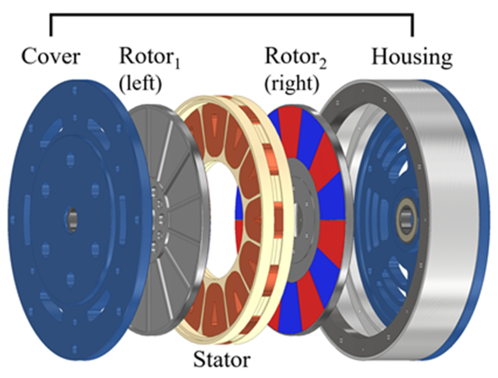
2. AFPM Generator Design

2.1. Design Specifications

AFPM generator design specifications are shown in Table 1.
In consideration of the performance of the engine that is to be used with the generator, the speed was limited to a maximum of 7000 rpm. Additionally, the maximum line voltage constant at no-load was limited to 11 mV/rpm or less in consideration of the AC/DC converter performance to be used for 48 V DC battery charging. The voltage and current values in this paper all represent RMS (root mean square) and not peak value. For the efficient operation of the maximum payload 3 kg UAV system, the efficiency and power density requirements of the generator are required as shown in Table 1, and the generator is operated without a separate cooling device.
The initial design of the generator used a quasi-three dimensional analysis model, which is a model from 3D geometry to a corresponding two dimensional model [1]. Table 2 shows the design results of the initial design model that satisfy the given constraints, and the 3D analysis model for a detailed design review of the rotor and stator is shown in Figure 2. Each of the six phases is indicated by the capital letters A to F, where LP is the phase inductance, RP is the phase resistance, and RL is the load resistance.

2.2. Rotor Design of the AFPM Generator

In the process of designing the rotor to increase the power density of the generator, three rotor topologies were compared, as shown in Figure 3. The volume and dimensions of the three rotors are all the same, and the thickness of the yoke used to increase the mechanical robustness of the rotor is also considered to have the same dimensions. The stator specifications, dimensions, and weight conditions are all the same. The only difference is the combination of the magnetization directions of the rotor’s PM.
As shown in Figure 3a, the Halbach arrangement in which four different magnetization directions form one magnetic pole is defined as Type-I. As shown in Figure 3b, a Halbach array composed of three different magnetization directions that can be combined relatively easily is defined as Type-II. As shown in Figure 3c, a typical pole arrangement that is magnetized in only one direction to form one pole is defined as a normal arrangement (NA).
The efficiency presented in Table 3 considers only copper loss at the stator coil and iron loss at the back yoke of the rotor PM. All models are designed with Litz wire so only DC copper loss is considered; eddy current loss is ignored. Even though all three models have similar efficiency values, when looking at the generated voltage, the voltages of Type-I and Type-II are 38.5% and 24.8% higher than the NA, respectively. Additionally, for the same current, the output power and output power density are evaluated to be 39.6% higher in Type-I and 25.6% higher in Type-II than the NA.
Despite having the same back yoke and rotor volume for all three types, the rotor core losses in Type-I and Type-II are significantly lower than the NA, demonstrating the advantage of using the Halbach array.
Since the output power of Type-I is excellent under the same conditions, the PM arrangement of the generator rotor was set as Type-I. Figure 4 shows the voltage and current waveforms in the stator coil that were generated when the Type-I model was analyzed. In the case of Type-II and the NA, the generated voltage values are different as shown in Table 3, but the waveforms are the same as shown in Figure 4. The phase difference of the waveforms in Figure 4 is due to the use of two pairs of balanced three-phase winding arrays electrically shifted by 30° to each other; this is shown in Figure 5. This winding arrangement is also referred to as a dual three-phase winding arrangement [10,11].

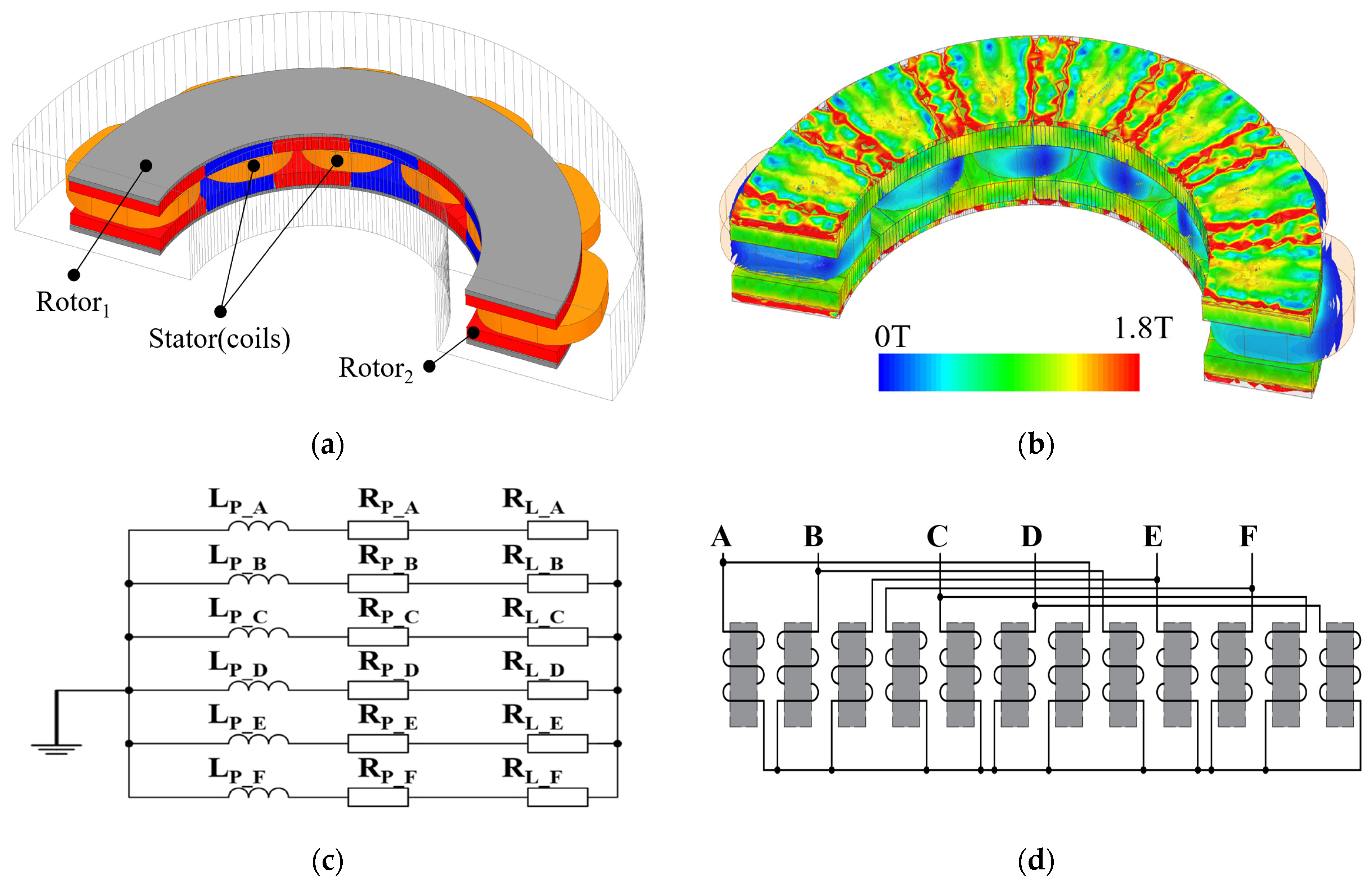
2.3. Stator Design of the AFPM Generator

In general, DC resistance loss is the main loss in the stator coil, and in the case of high-speed operation, AC resistance loss is also considered. However, in the case of a slotless or coreless stator that does not form teeth with a magnetic material (with or without a back yoke), the magnetic flux change occurs directly in the coil; thus, even at a low frequency of several hundred Hz, severe eddy current loss can happen in the coil depending on the diameter of the conductor. Although DC resistance and AC resistance losses occur only in the state of load operation with the current flowing, eddy current loss in the coil occurs not only during load operation but also during no-load operation.
The best way to reduce the eddy current loss of a conductor is to use Litz wire that divides the conductor into multiple strands. However, when using Litz wires with each coated strand for winding, the number of turns that can be wound around the same coil cross-sectional area is reduced by half compared to the normal conductor. Therefore, when using Litz wire, an increase in the volume of the motor or generator is inevitable because the coil cross-sectional area must be at least doubled or the rotor PM size and the number of coil turns must be increased to achieve the same output power as a model using a normal conductor.
For drone applications requiring a high power density, the trade-off between thermal and weight reduction problems should be considered. Therefore, in the stator design of the AFPM generator with the coreless stator, the characteristics of coil types under the same volume and weight conditions were compared analytically and experimentally, as shown in Table 4.
The Coil-I and Coil-II models use a general conductor, and the parallel circuit is different in terms of the number of equivalent series turns; however, the phase resistance is the same. Therefore, the diameter of the coil conductor used is different. In the Coil-III model, a Litz wire that has a cross-sectional area equivalent to that of Coil-I was used, and the number of turns in a series decreased due to the difference in the slot fill factor.
For the numerical calculation of the eddy current loss in the coils for each model, the most basic formula cited in several related papers [3,12] is used, as shown in (1):
Pe = (πld4Bpk2ω2)/(32ρ)
where l is the coil side length, d is a round conductor diameter, Bpk is the peak value of flux density, ω is the fundamental electrical angular speed, and ρ is the conductor resistivity.
For more detailed calculations, the magnetic flux density between the coil layers can be calculated differently, or the direction component of the magnetic flux density and the harmonic component can be divided and examined [3]. However, if the magnetic flux density distribution in the target stator coil is analyzed, as shown in Figure 6 and Figure 7, it has the following characteristics:
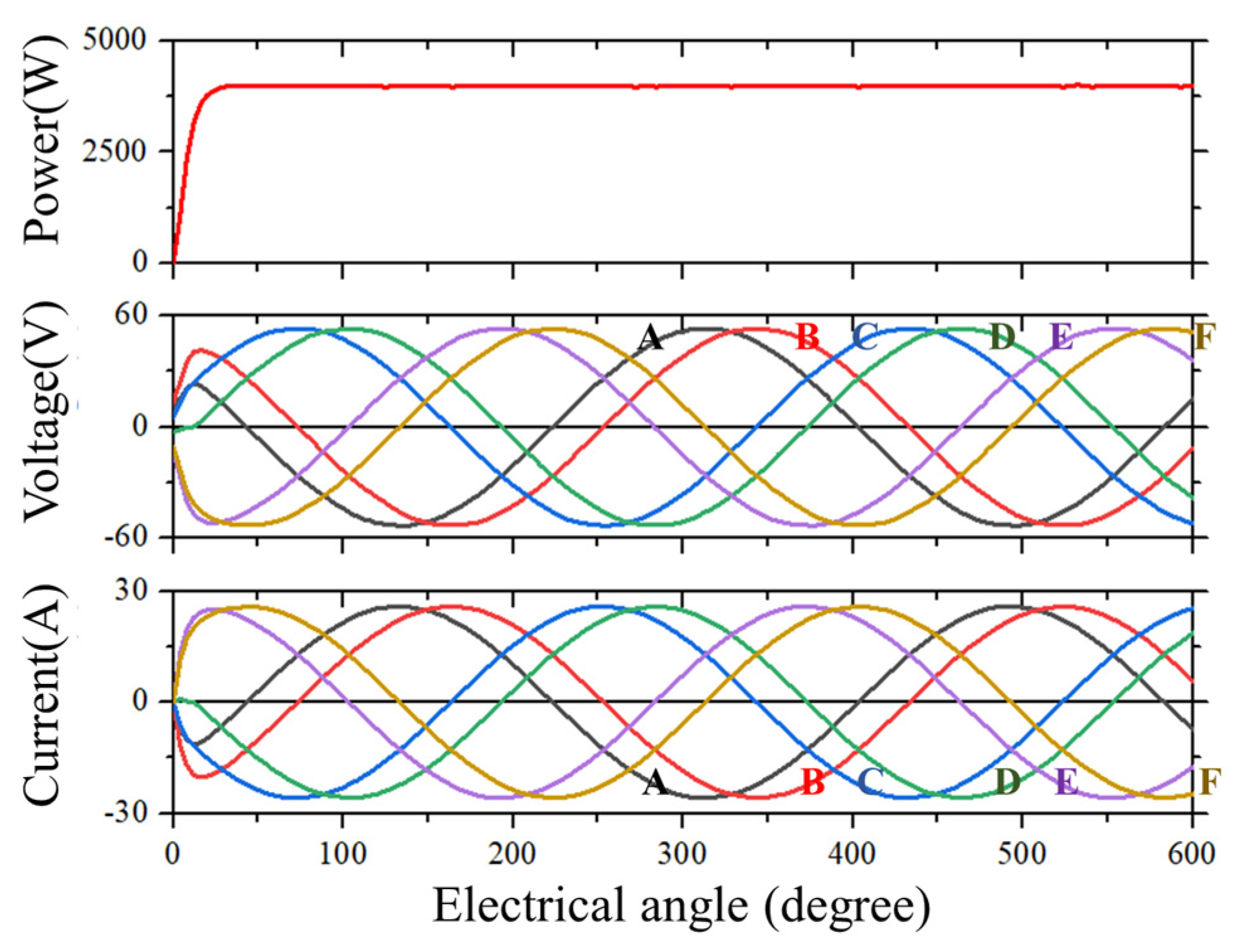
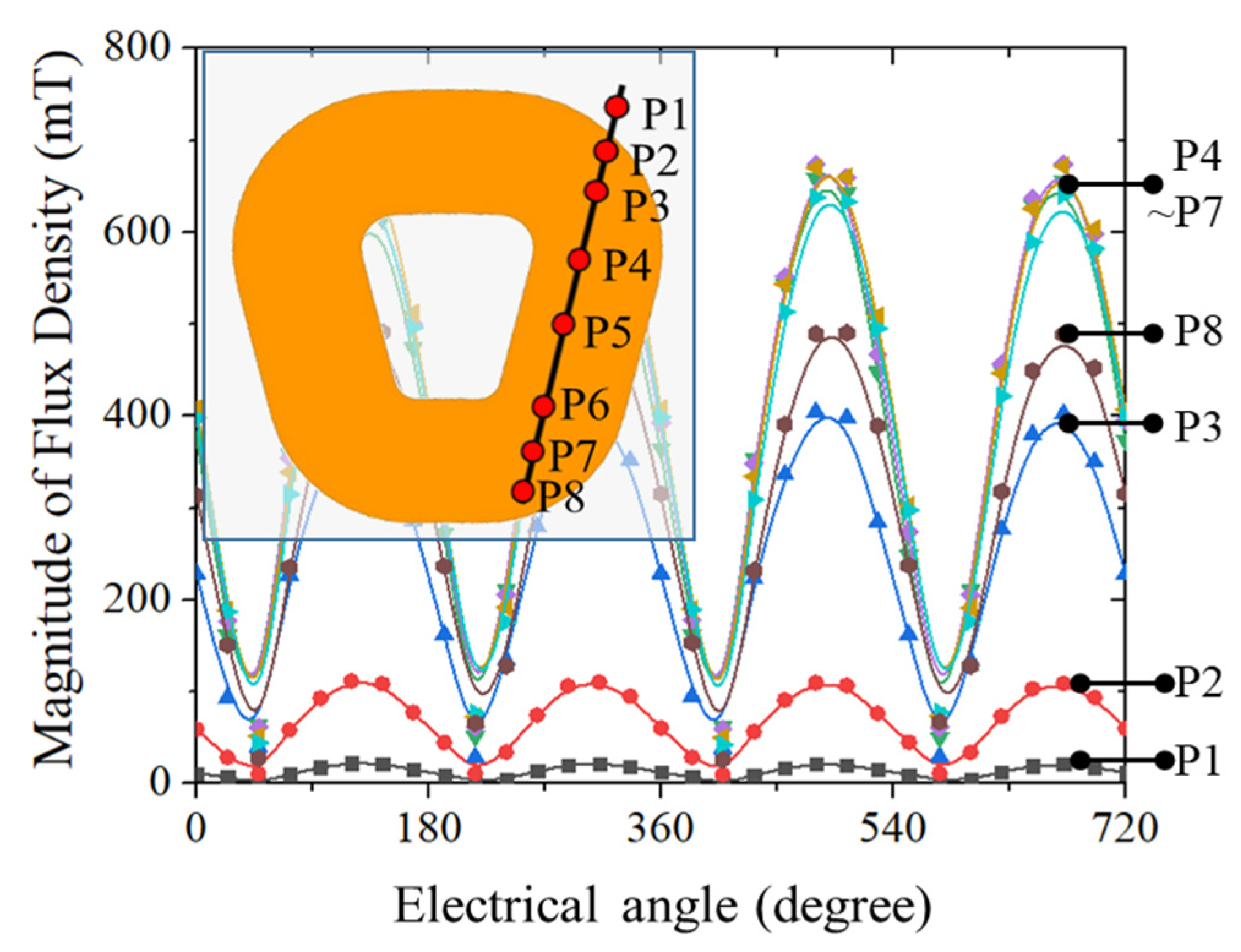
  • The change of magnetic flux density over time is sine, and the harmonic component is negligible;
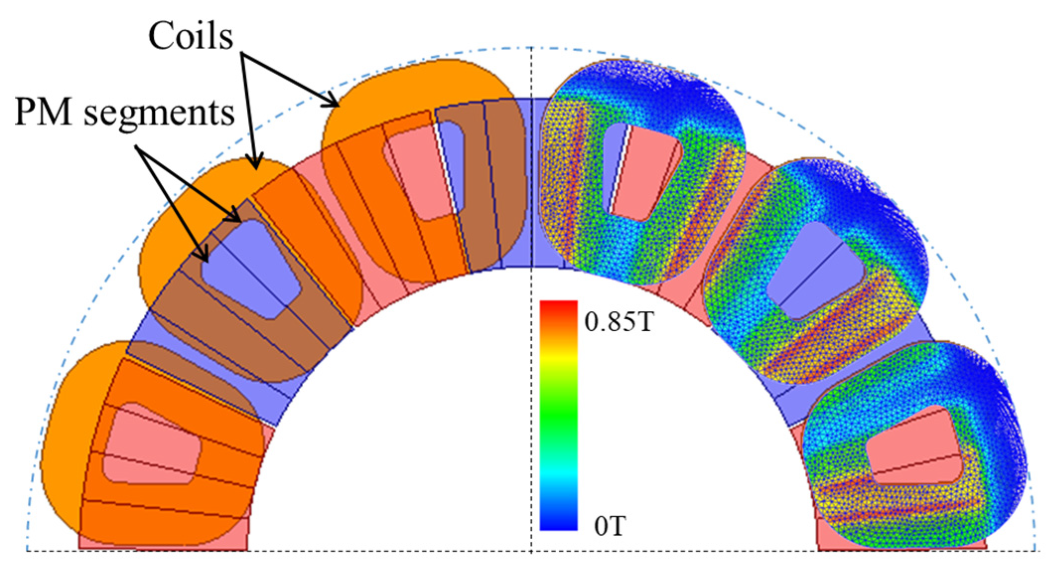
  • Since the change in magnetic flux density from point P4 to point P7, which is the straight side of the coil, is similar, it can be represented by one value. The magnetic flux density variation between the layers of the coil is negligible;
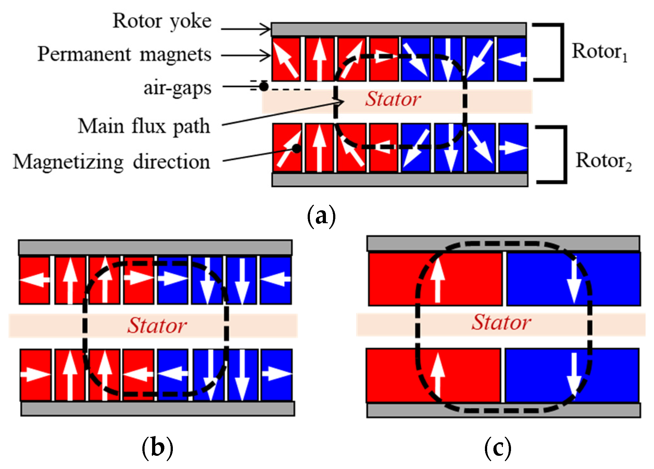
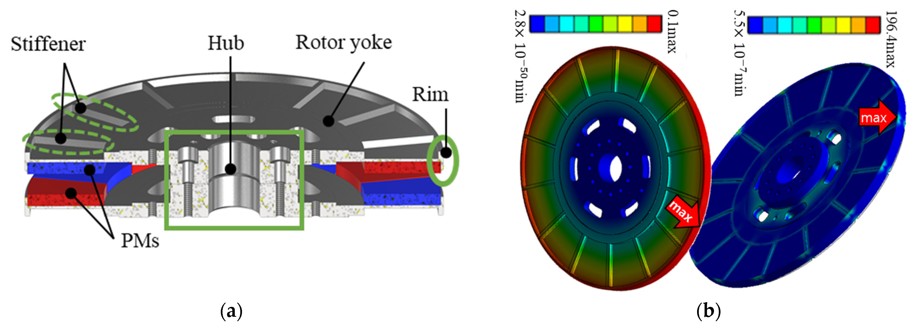
  • The magnetization directions of the rotor permanent magnets facing each other are opposite to each other as shown in Figure 3a, and the axial length of the coil is short. Therefore, it can be seen that the magnetic flux passing between points P4 to P7 of the coil has only the axial component.
In addition, the relative comparison with the coil model is important, so it was calculated only as the maximum average magnetic flux density in one straight conductor.
The lower middle part of Table 4 shows the results comparing the eddy current loss power of the coil calculated by (1) and the measured loss power for each model during a no-load operation at a rotational speed of 5000 rpm. If the eddy current loss in the segmented permanent magnet is neglected, the measured value can only be evaluated by the mechanical and conductor eddy current losses. However, since the Coil-III model makes the stator coil with Litz wire so that the conductor eddy current loss is also negligible, most of the measured losses of the Coil-III model can be considered as mechanical losses. Since all were made under the same conditions except for the stator winding, the mechanical losses of the Coil-I and Coil-II models are evaluated similarly to those of Coil-III. After subtracting the mechanical loss of Coil-III from the measured losses of Coil-I and Coil-II, it can be seen that the eddy current loss values of Coil-I and Coil-II models are similar to the calculated values.
At the bottom of Table 4, the temperatures in the coil measured during the no-load test of each model are compared. The maximum temperature measured at the coil using three thermocouples during the test held for 30 s at each speed point in increments of 500 rpm, from 500 rpm to 6000 rpm. The housing of the manufactured generator is as shown in Figure 1, and the temperature of Coil-I and Coil-II was severely increased while the room temperature was 25 degrees Celsius across the board. From the comparison of Coil-I and Coil-II, it can be seen that the effect of the parallel circuit with the possibility of a circulating current is not large; rather, the loss decreases as the conductor diameter decreases. This can confirm that the loss is significantly reduced in Coil-III, which has the smallest conductor diameter. Therefore, the stator was determined with the Coil-III model that could completely reduce the conductor eddy current loss as a heat source.

3. Mechanical and Thermal Analysis

A mechanical analysis and thermal analysis were performed on the models that were determined through rotor and stator design introduced in the previous chapter. That is, when the rotor has the Type-I PM arrangement in Figure 3a and the stator has the Coil-III specification in Table 4, the mechanical analysis related to the rotor yoke and shaft of this model and the examination of temperature stability were performed. In order to reduce the weight of the system to which the generator was to be attached, parts of the generator were minimized by sharing parts with the system. Therefore, in the process of the mechanical and thermal analysis of the model that was ultimately determined, the housing and cover were omitted; instead, a jig for fixing the generator was considered for comparison with the test results.

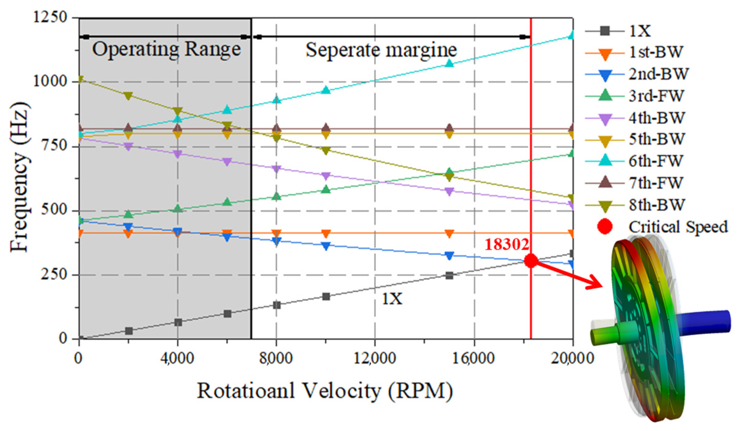
3.1. Mechanical Analysis

In a coreless AFPM generator, the main forces affecting the mechanical structure are usually the centrifugal force and the attraction force of the PMs [13].
First, centrifugal force causes the deviation of PMs arranged in the circumferential direction of the edges of the rotor yoke. The main cause is the occurrence of shear stress by centrifugal force on the plane where the rotor frame and PM are bonded [14]. The upper part of Figure 8 shows the cross-section of the designed generator rotor, which has rim parts with a height that is 75% of PM thickness to prevent the deviations in the radial direction of the PMs caused by centrifugal force.
Second, the axial attraction force due to the magnetism of the PMs attached to the two rotors causes a bending moment with the hub part assembled on the rotary axis as a support, resulting in deflection [15,16]. The direction of deflection is the direction of reducing the air gap, which in turn reduces the performance and stability of the generator, and a robust design of the rotor frame is required. To increase the stiffness in the axial direction of the rotor frame, the stiffener was designed as shown in the upper part of Figure 8 and the thickness of the hub acting as the support was designed to be relatively thicker than the outer part.
A stress analysis was performed to check the designed rotor frame’s deflection and stress distribution by magnetic force, and the lower part of Figure 8 is the result of this stress analysis. The maximum deflection was shown at the edge of the rotor frame at 0.11 mm, which means there was a maximum reduction of 22% in the designed 0.5 mm air-gap length. The von Mises stress resulted in 196.44 Mpa in the same area where the maximum deflection occurred. The yield strength of S45C, the material of the rotor frame, is 490 Mpa, and the maximum stress that occurred was lower than this, meaning that it was mechanically stable.
Finally, the rotor dynamics were performed to confirm the dynamic stability of the rotor system. Figure 9 is the Campbell diagram showing the result of the analysis. The critical speed, which is when the natural vibration mode is the bending mode of the rotating shaft, was shown to be 18,302 rpm. This is illustrated in the mode shape shown in the lower right-hand corner of Figure 10. More than 20% of the separation margin was secured for the maximum operating speed of the generator at 7000 rpm, and no whirling vibration of the rotor system was expected to occur.

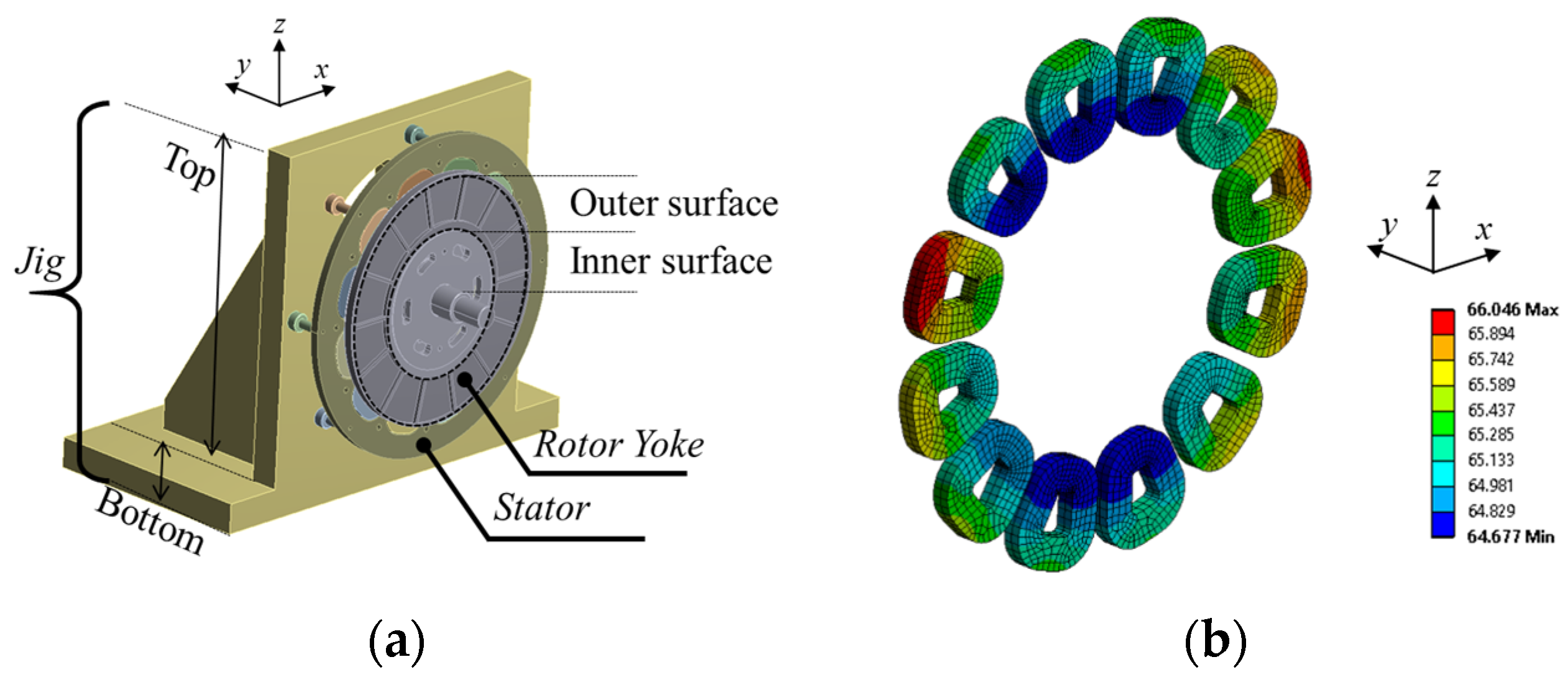
3.2. Thermal Analysis

A thermal analysis was performed under rated conditions to ensure the normal and safe operation of the designed model. Since Litz wire and segmented PM were used, the eddy current loss in the coil and PM was negligible, and the main heat source was the DC copper loss. The other heat sources were core losses in the rotor yoke and mechanical losses in the bearings. Although copper loss and iron loss can be calculated through parameters obtained through electromagnetic field analyses and empirical formulas [17,18,19,20,21,22], respectively, mechanical loss varies depending on the parts and the manufacturing method of the manufactured model. Therefore, it was assumed that the mechanical loss was about 7% of the 3 kW rated output power with reference to the prototype reviewed, until the final model was decided. Moreover, it was assumed that the generator operated under natural cooling conditions at a room temperature of 28 °C. All input parameters for the analysis are shown in Table 5.
The connection coefficient, defined in the boundaries of the model, used empirical values. In the case of the rotor yoke, the values of 100 and 200 W/m2K were applied to the inner and outer surfaces of the rotor, respectively, considering that rotation resulted in a fan-like cooling effect. On the other hand, the jig was separated into a top plate and a bottom plate, and the jig top plate to which the generator was attached had only a slight flow of air, with a value of 10 W/m2K applied. The lower plate of the jig was defined as infinite, assuming a situation in which heat could escape infinitely due to its connection to the dynamo steel base.
The final designed model including the test jig was modeled in 3D as shown in Figure 10a, and the thermal analysis was performed using FEM [23,24,25,26]. When the temperature was saturated, the highest temperature was the stator coil with the largest loss, as shown in Figure 10b. Table 6 shows the range of temperature distribution by dividing the generator into coils, rotor yokes, PMs, and bearings. Representatively, when looking at the material used for coils and PMs that are most vulnerable to temperature, Litz wire has a class F thermal index with a maximum operating point of 155°C, and PM with SH grade has a maximum operating point of 150 °C. It can be seen that the heat generated by the generator during the rated operation is in the stable range.

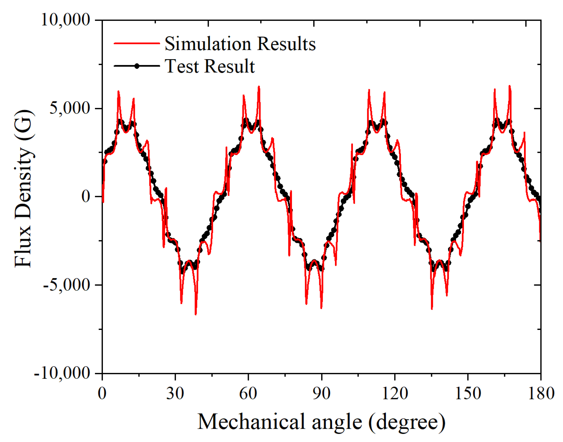
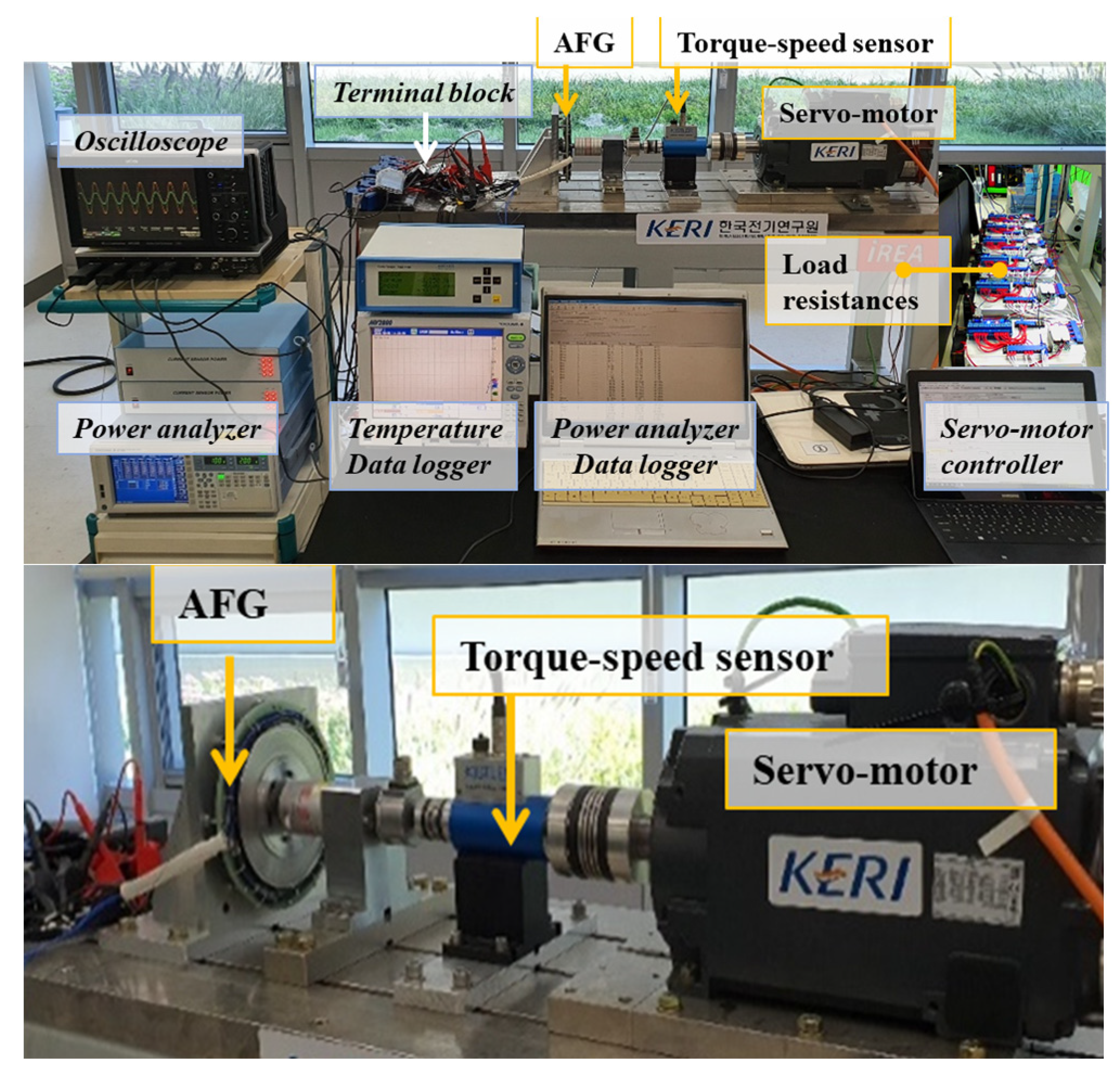
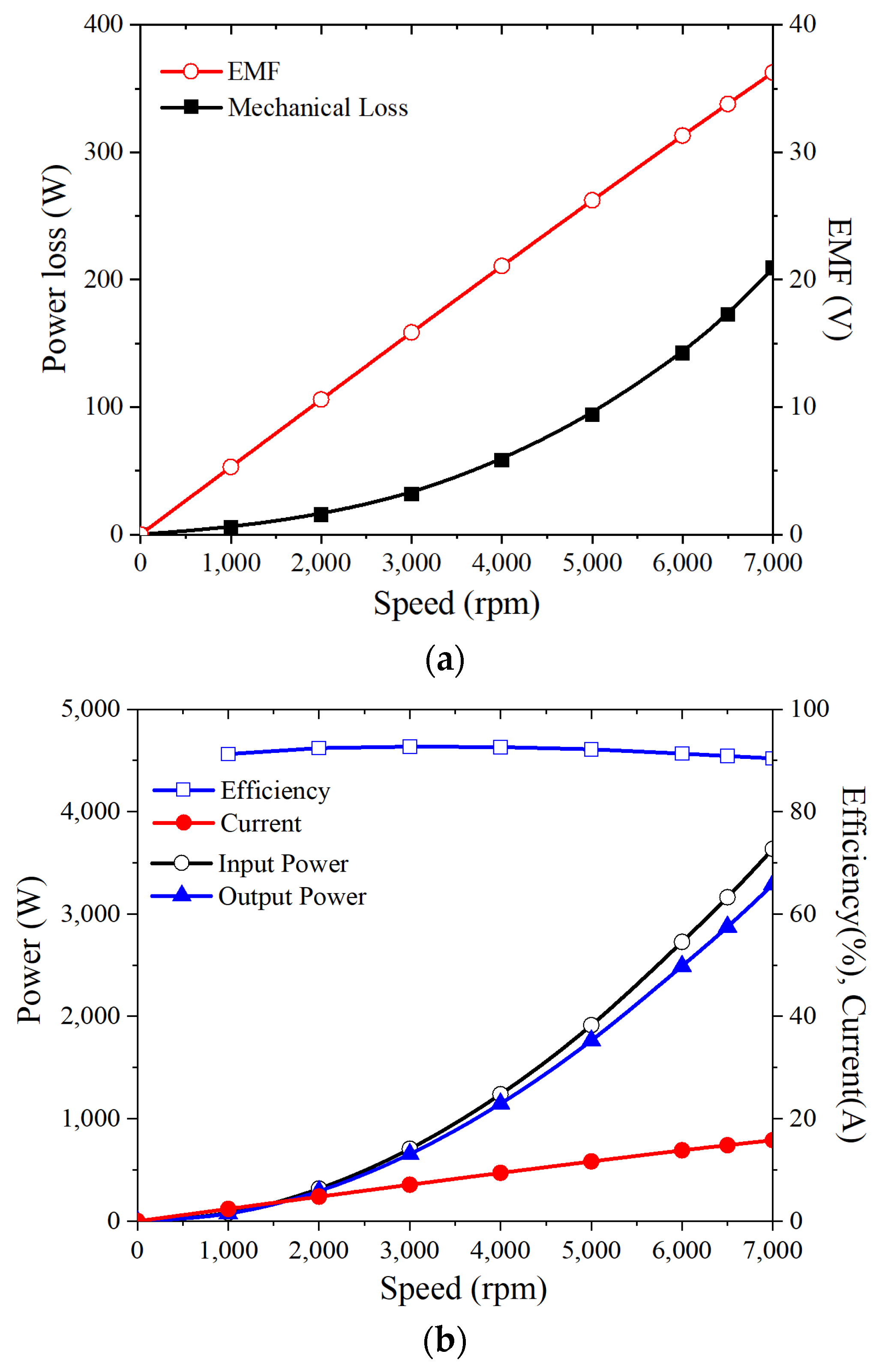
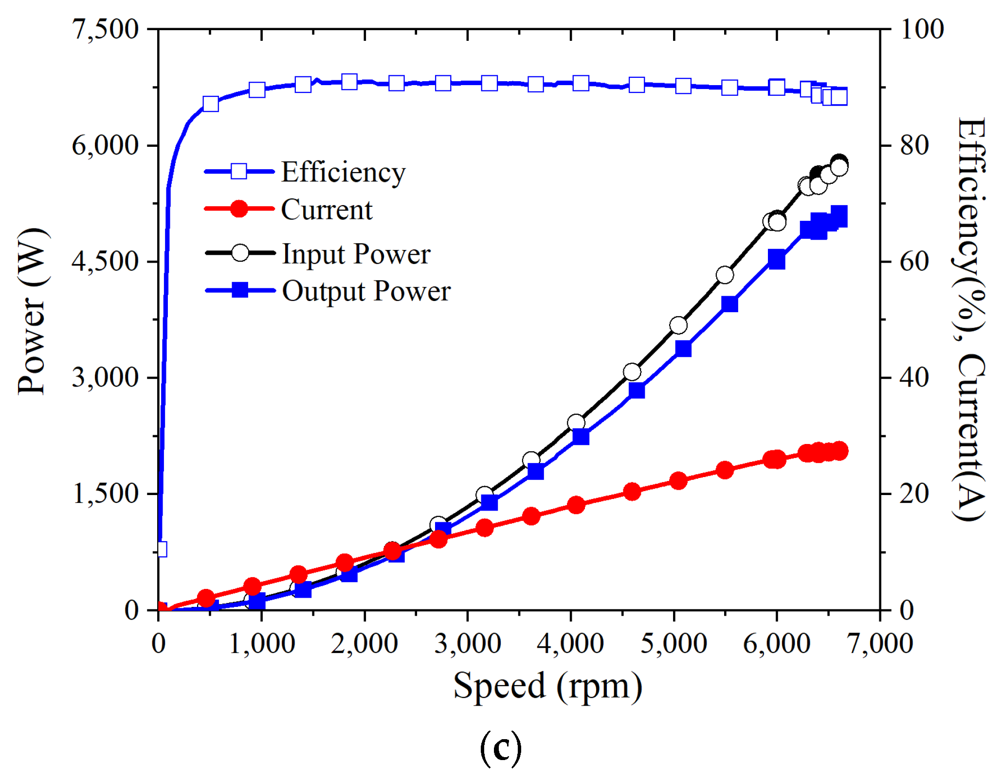
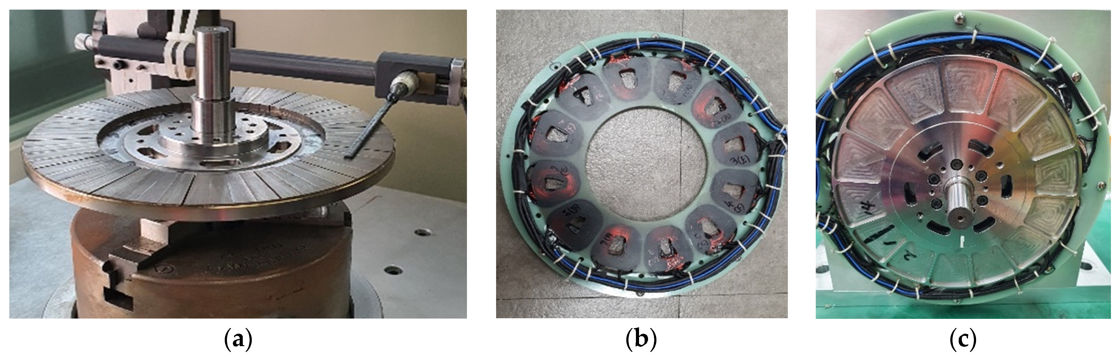
4. Experimental Validation and Conclusions

The prototype of the model was finally decided based on the electromagnetic field design and mechanical thermal analysis that were produced as shown in Figure 11. In order to check whether the PM arrangement of the rotor composed of the Halbach array was properly manufactured, the magnetic flux density of the PM surface was measured, as shown in Figure 11a. As compared in Figure 12, it can be confirmed that the trends of the predicted values and the measured values match well through the electromagnetic field analysis. Higher harmonics appearing in the analysis compared to the measured values can be regarded as calculation errors according to the element mesh state.
As shown in Figure 13, a dynamo set was constructed to test the generator. By connecting a 2 ohm resistive load per phase to the generator, a power generation output of 3.1 kW could be obtained at 6500 rpm. A higher output power could be achieved by connecting a resistor of 1 ohm per phase to the generator. Figure 14a shows the no-load test results according to speed. Moreover, Figure 14b,c shows the load test results according to speed for a resistive load of 2 and 1 ohm, respectively. In the no-load operation, it can be seen that the back EMF is linear with speed, whereas the power loss is non-linear. When the resistive load is 2 ohm, the rated power of 3 kW output occurs at around 7000 rpm, and the mechanical loss at this time is about 200 W. On the other hand, when the resistive load is 1 ohm, the rated output power occurs at around 5000 rpm, and it can be seen that the mechanical loss at this time is about 100 W. It was confirmed through the test that the maximum efficiency was 93.2% at 3000 rpm when the resistive load was 2 ohm, and the maximum output power was 5 kW at 6500 rpm when the resistive load was 1 ohm. Accordingly, the ratio of the maximum output power to the generator weight is 2.5 kW/kg, which satisfies all the design conditions required in Table 1.
Figure 15 shows the test results confirming that it can be operated for more than 30 min while maintaining a constant output power of over 3 kW. It can be seen that the maximum temperature of the measured coil is about 40 °C, which is lower than the predicted temperature in the analysis. Errors may have accumulated in various assumptions during the calculation process, but one main cause is considered to be the value of the convection coefficient. If this is compensated by reflecting the test error, it is expected that more accurate results can be predicted in a similar system. As a temperature lower than the predicted temperature is measured, it can be seen that the designed generator can be operated stably with a greater margin for the temperature.
It is judged that the above design process and review results can be used as reference materials for other studies of the design of an unmanned aerial vehicle generator using AFPM.

Author Contributions

Conceptualization, J.-Y.L.; methodology, J.-Y.L.; validation, J.-H.L.; writing—original draft preparation, J.-Y.L.; writing—review and editing, J.-H.L. and T.K.N.; All authors have read and agreed to the published version of the manuscript.

Funding

This research was funded by the KERI Primary research program of MSIT/NST, grant number 21A01052.

Institutional Review Board Statement

Not applicable.

Informed Consent Statement

Not applicable.

Data Availability Statement

Not applicable.

Acknowledgments

This research was supported by the KERI Primary research program of MSIT/NST (No. 21A01052).

Conflicts of Interest

The authors declare no conflict of interest.

References

  1. Lee, J.Y.; Koo, D.H.; Moon, S.R.; Han, C.K. Design of an Axial Flux Permanent Magnet Generator for a Portable Hand Crank Generating System. IEEE Trans. Magn. 2012, 48, 2977–2980. [Google Scholar] [CrossRef]
  2. Di Gerlando, A.; Foglia, G.M.; Iacchetti, M.F.; Perini, R. Axial Flux PM Machines with Concentrated Armature Windings: Design Analysis and Test Validation of Wind Energy Generators. IEEE Trans. Ind. Electron. 2010, 58, 3795–3805. [Google Scholar] [CrossRef]
  3. Arkadan, A.A.; Hijazi, T.M.; Masri, B. Design Evaluation of Conventional and Toothless Stator Wind Power Axial-Flux PM Generator. IEEE Trans. Magn. 2017, 53, 1–4. [Google Scholar] [CrossRef]
  4. Lee, J.Y.; Park, B.G.; Koo, D.H. Analysis of Mechanical Fixation Made of Aluminum Alloy in an Axial Flux Permanent Magnet Machine. J. Magn. 2014, 19, 309–313. [Google Scholar] [CrossRef]
  5. Vun, S.T.; McCulloch, M.D.; Leong, C.Y. The development of an electromagnetic analytical design tool for mega-watt-scale YASA generators. In Proceedings of the IET Conference on Renewable Power Generation (RPG 2011), Edinburgh, UK, 6–8 September 2011; pp. 1–6. [Google Scholar]
  6. Woolmer, T.J.; McCulloch, M.D. Analysis of the Yokeless And Segmented Armature Machine. In Proceedings of the 2007 IEEE Internation-al Electric Machines & Drives Conference, Antalya, Turkey, 3–5 May 2007; pp. 704–708. [Google Scholar]
  7. Aydin, M.; Huang, S.; Lipo, T.A. Axial Flux Permanent Magnet Disc Machine: A Review. In Proceedings of the 2004 Conference Record of SPEEDAM; 2004; pp. 61–71. Available online: https://www.researchgate.net/publication/228449891_Axial_flux_permanent_magnet_disc_machines_A_review (accessed on 3 December 2021).
  8. Park, Y.; Kim, H.; Jang, H.; Ham, S.-H.; Lee, J.; Jung, D.-H. Efficiency Improvement of Permanent Magnet BLDC With Halbach Magnet Array for Drone. IEEE Trans. Appl. Supercond. 2020, 30, 1–5. [Google Scholar] [CrossRef]
  9. Wiltuschnig, I.P.; Eckert, P.R.; Dorrell, D.; Filho, A.F.F. A Study of the Influence of Quasi-Halbach Arrays on a Torus Machine. IEEE Trans. Magn. 2016, 52, 1–4. [Google Scholar] [CrossRef]
  10. Hu, Y.; Zhu, Z.; Liu, K. Current Control for Dual Three-Phase Permanent Magnet Synchronous Motors Accounting for Current Unbalance and Harmonics. IEEE J. Emerg. Sel. Top. Power Electron. 2014, 2, 272–284. [Google Scholar]
  11. Barcaro, M.; Bianchi, N.; Magnussen, F. Analysis and Tests of a Dual Three-Phase 12-Slot 10-Pole Permanent-Magnet Motor. IEEE Trans. Ind. Appl. 2010, 46, 2355–2362. [Google Scholar] [CrossRef]
  12. Wang, R.; Kamper, M.J. Calculaton of Eddy Current Loss in Axial Field Permanent-magnet Machine with Coreless Stator. IEEE Trans. Energy Conv. 2004, 19, 532–538. [Google Scholar] [CrossRef]
  13. Mahmoudi, A.; Rahim, N.A.; Hew, W.P. Axial-flux permanent-magnet machine modeling, design, simulation and anal-ysis. Sci. Res. Essays 2011, 6, 2525–2549. [Google Scholar]
  14. Parviainen, A. Design of Axial-Flux Permanent-Magnet Low-Speed Machines and Performance Comparison between Radi-al-Flux and Axial-Flux Machines. Ph.D. Thesis, Lappeenranta University, Lappeenranta, Finland, April 2005. [Google Scholar]
  15. Hikmawan, M.; Kasim, M.; Irasari, P.; Widiyanto, P. Analysis of magnet shape influence on rotor deflection on axial flux permanent magnet generator. In Proceedings of the 2017 International Conference on Sustainable Energy Engineering and Application (ICSEEA), Jakarta, Indonesia, 23–24 October 2017; pp. 91–97. [Google Scholar]
  16. Zhang, B.; Seidler, T.; Dierken, R.; Doppelbauer, M. Development of a Yokeless and Segmented Armature Axial Flux Machine. IEEE Trans. Ind. Electron. 2015, 63, 2062–2071. [Google Scholar] [CrossRef]
  17. Luu, P.T.; Lee, J.-Y.; Lee, J.-H.; Park, J.-W. Electromagnetic and Thermal Analysis of Permanent-Magnet Synchronous Motors for Cooperative Robot Applications. IEEE Trans. Magn. 2020, 56, 1–4. [Google Scholar] [CrossRef]
  18. Luu, P.T.; Lee, J.Y.; Lee, J.H.; Park, J.W. Electromagnetic and Thermal Analysis of a Permanent Magnet Motor Consid-ering the Effect of Articulated Robot Link. Energies 2020, 13, 3239. [Google Scholar] [CrossRef]
  19. Lee, J.Y.; Luu, P.T. Electric Motor Design of an Integrated Motor Propulsor for Unmanned Vehicles: The Effect of Wa-terproofing Can. Energies 2020, 13, 2227. [Google Scholar] [CrossRef]
  20. Lee, J.; Kim, J.; Moon, S.; Chang, J.; Chung, S.; Kang, D.; Hong, J. Dynamic Characteristic Analysis Considering Core Losses in Transverse Flux Linear Machine With Solid Cores. IEEE Trans. Magn. 2009, 45, 1776–1779. [Google Scholar]
  21. Jang, S.; Cho, H.; Choi, S. Design and Analysis of a High-Speed Brushless DC Motor for Centrifugal Compressor. IEEE Trans. Magn. 2007, 43, 2573–2575. [Google Scholar] [CrossRef]
  22. Roshen, W.A. A Practical, Accurate and Very General Core Loss Model for Nonsinusoidal Waveforms. IEEE Trans. Power Electron. 2007, 22, 30–40. [Google Scholar] [CrossRef]
  23. Huang, Y.; Zhu, J.; Guo, Y. Thermal Analysis of High-Speed SMC Motor Based on Thermal Network and 3-D FEA With Rotational Core Loss Included. IEEE Trans. Magn. 2009, 45, 4680–4683. [Google Scholar] [CrossRef]
  24. Qi, J.; Hua, W.; Zhang, H. Thermal Analysis of Modular-Spoke-Type Permanent-Magnet Machines Based on Thermal Network and FEA Method. IEEE Trans. Magn. 2019, 55, 1–5. [Google Scholar] [CrossRef]
  25. Srinivas, K.N.; Arumugam, R. Analysis and characterization of switched reluctance motors: Part II. Flow, thermal, and vibration analyses. IEEE Trans. Magn. 2005, 41, 1321–1332. [Google Scholar] [CrossRef]
  26. Huang, Y.; Zhu, J.; Guo, Y.; Lin, Z.; Hu, Q. Design and Analysis of a High-Speed Claw Pole Motor With Soft Magnetic Composite Core. IEEE Trans. Magn. 2007, 43, 2492–2494. [Google Scholar] [CrossRef] [Green Version]
Figure 1. DR-SS generator configuration example.
Energies 14 08509 g001
Figure 2. Three dimensional FEM analysis model for AFPM generator: (a) analysis periodic model, (b) flux density distribution, (c) external load-resistance circuit, and (d) six-phase winding pattern for stator.
Energies 14 08509 g002
Figure 3. Three rotor models according to the arrangement of the magnetization direction: (a) Type-I; (b) Type-II; and (c) normal array (NA).
Energies 14 08509 g003
Figure 4. Voltage and current waveforms of rotor Type−I.
Energies 14 08509 g004
Figure 5. Phase vectors of the six-phase winding arrangement.
Energies 14 08509 g005
Figure 6. Phase vector of the six-phase winding arrangement.
Energies 14 08509 g006
Figure 7. Magnetic flux density changes over time in the coils during the no-load condition.
Energies 14 08509 g007
Figure 8. (a) Structure of the rotor; and (b) stress analysis result for the rotor frame.
Energies 14 08509 g008
Figure 9. Result of the rotor critical speed analysis (Campbell diagram).
Energies 14 08509 g009
Figure 10. (a) Three dimensional analysis model; and (b) temperature distribution in the coils.
Energies 14 08509 g010
Figure 11. Fabricated (a) rotor; (b) stator; and (c) rotor–stator assay.
Energies 14 08509 g011
Figure 12. Comparison of flux density on PM.
Energies 14 08509 g012
Figure 13. TEST set for the AFPM generator.
Energies 14 08509 g013
Figure 14. No-load and load test results according to speed and load resistance: (a) No-load test; (b) 2-ohm/phase resistance load test; and (c) 1-ohm/phase resistance load test.
Energies 14 08509 g014aEnergies 14 08509 g014b
Figure 15. Temperature saturation test (resistive load is 2 ohm).
Energies 14 08509 g015
Table 1. Design specifications for AFPM generator.
ParameterValueUnit
Max speed≤7000rpm
Output power≥3000W
No-load voltage constant≤11mV/rpm
Efficiency≥93%
Power density≤2.3W/kg
Cooling conditionNatural cooling
Table 2. Initial design results for the AFPM generator.
ParameterValueUnit
No. of phases6
No. of poles/slots14 poles/12 slots
Outer diameter of rotor162mm
Air-gap length (one-side)0.5mm
Total axial thickness17mm
PM materialNdFeB(Br = 1.3T)
Table 3. Comparison of the analysis results for the three rotor models.
ParameterType-IType-IINA
Rated output power (W)3982.4
(139.6%)
3583.9
(125.6%)
2853.6
(100%)
Phase voltage (V)37.4
(138.5%)
33.7
(124.8%)
27
(100%)
Core loss (W)1.51.33.7
Copper loss (W)112.089.857.8
Efficiency (%)97.297.597.9
Weight (kg)1.341.341.34
Power density (W/kg)2.97
(139.6%)
2.67
(125.6%)
2.13
(100%)
Rated speed (rpm)650065006500
Phase current (A)18.116.213
Current density (A/mm2)15.914.311.5
No. of parallel circuits222
No. of turns per coil424242
No. of strands of wire707070
Conductor diameter (mm)0.10.10.1
Rotor avg. flux density (T)1.31.21.4
Rotor max. flux density (T)2.32.32.8
Table 4. Comparison of no-load characteristics for the three stator models.
ParameterCoil-ICoil-IICoil-III
Rotating speed (rpm)500050005000
No. of parallel circuits211
No. of turns per coil723636
No. of serial turns per phase727236
No. of strands1170
Conductor diameter (mm)0.851.20.1
Slot fill factor (%)626231
Phase resistance (Ohm)0.0840.0810.04
Calculated eddy-current loss power of coils (W)110.6
(100%)
219.7
(199%)
0.74
(0.7%)
Measured loss power of each prototype (W)122
(100%)
242
(198%)
39
(32%)
Max temperature (°C)72.6103.731.3
Table 5. Input parameters for the thermal analysis.
ParameterValue
Output power (W)3000
Speed (rpm)7000
Current (A)15.5
Copper loss (W)96.6
Core loss (W)1.5
Mechanical loss (W)200
Room temperature (°C)28
Convection coefficient on rotor yoke (inner/outer) (W/m2K)100/200
Convection coefficient on jig (W/m2K)10/Infinite
Table 6. Thermal analysis results.
ParameterValue
Coil temperature range (°C)65–66
Rotor yoke temperature range (°C)39–51
PM temperature range (°C)42–47
Bearing temperature range (°C)56–67
Publisher’s Note: MDPI stays neutral with regard to jurisdictional claims in published maps and institutional affiliations.

