Article

RES Based Islanded DC Microgrid with Enhanced Electrical Network Islanding Detection

by
Muhammad Umair Shahid
1,2,*,
Thamer Alquthami
3,*,
Abubakar Siddique
1,
Hafiz Mudassir Munir
4,
Saqlain Abbas
5 and
Zulkarnain Abbas
6
1
Department of Electrical Engineering, Khwaja Fareed University of Engineering & Information Technology (KFUEIT), Rahim Yar Khan 64200, Pakistan
2
School of Electronics, Information & Electrical Engineering (SEIEE), Smart Grid R&D Centre, Shanghai Jiao Tong University, Shanghai 200240, China
3
Department of Electrical and Computer Engineering, King Abdulaziz University, Jeddah 21589, Saudi Arabia
4
Department of Electrical Engineering, Sukkur IBA University, Sukkur 65200, Pakistan
5
Department of Mechanical Engineering, Narowal Campus, University of Engineering & Technology (UET) Lahore, Lahore 54890, Pakistan
6
NFC Institute of Engineering and Technology, Multan 59300, Pakistan
*
Authors to whom correspondence should be addressed.
Energies 2021, 14(24), 8432; https://doi.org/10.3390/en14248432
Submission received: 15 October 2021 / Revised: 4 December 2021 / Accepted: 9 December 2021 / Published: 14 December 2021
(This article belongs to the Special Issue Smart Microgrid Energy Management Solutions)

Abstract

:
An electrical islanding detection method for DC microgrid (MG) is proposed in this paper. Unlikely conventional AC MG system protection has been challenging for the DC MG system. The goal of the proposed scheme is to detect the islanding intelligently within the agent nodes. The proposed islanding detection technique detects the electrical link failure intelligently, and if any electrical link failure occurs, then the proposed technique maintains the MG operation and load sharing. Islanding detection is carried out using an injection signal and utilizes the existing communication network to check network connectivity. After checking the network connectivity, all the nodes maintain the look-up table of the connected network. This research work illustrates that the proposed electrical islanding detection technique is effective in maintaining the DC MG operation in the case of an electrical islanding/link failure scenario. The proposed scheme’s performance is checked through MATLAB/Simulink for the detection of islanding and maintaining the operation.

Graphical Abstract

1. Introduction

Islanding Detection is an essential operation condition in integrating the DGU’s to the large electrical network. In case of unscheduled dis-connection from the main grid, a distributed renewable-based generating microgrid (MG) can supply load by forming an island. This way load supply is met by using MG generating units. MG can be centralized or de-centralized to regulate system operation and safely restore power [1,2,3,4]. The MG model rapidly arises as a flexible method to aggregate diverse dispensed and intermittent renewable energy resources (RESs) and storage devices with the electrical grid safely and reliably. An MG can be operated in islanded mode or grid-connected mode. Since an MG is deliberately designed to supply local loads in islanded mode, traditional anti-islanding techniques pose a challenge. In the case of electrical islanding, analysis of the DC MG can be carried out using islanding detection methods. Islanding detection methods are generally divided into active, passive, and communication-based controls [5,6,7]. Communication-based islanding detection algorithms mainly consider the status of the protection devices to detect islanding and modify the control. The communication-based detection method requires an extensive communication network, this can be simply achieved using a hierarchical control communication network in MG. Whereas, active techniques utilize perturb and observe methods, which have a higher detection zone as compared to passive techniques [8,9,10].
These days research is carried out on the extension of sustainable power sources in the electrical network as a potential answer for the ecological security and deficiency of energy when the traditional energy resources will be depleted. Furthermore, the advancement of the storage capacity scenarios such as ultracapacitors and batteries, and DC loads (home apparatuses, electric vehicles, Data centers, and variable speed drives) are essentially expanded [11].
Physical electrical islanding detection in AC and DC network grids is a serious problem, because the lack to detect of the islanding may lead the grid to instable operation, and also it is a risk to the utility users. While a critical study has been carried out on AC system islanding, DC network islanding detection strategies are in the developing phase. Most common strategies for islanding identification in DC networks use over/under voltage ranges (which fall flat in case the load is close to the generation during the fault) or the injection of progressively large perturbation. A novel impedance-based strategy for islanding detection is presented. This technique is utilizing a digital lock-in amplifier technique combined with sensors usually incorporated into the PV network. Using the impedance, this strategy can rapidly recognize the islanding event and act accordingly [12].
DC systems have a few benefits contrasted with AC systems. For example, system productivity is higher and losses are less due to the utilization of inverters for DC loads in the network of AC systems [13,14,15,16]. Hence, DC systems have been expanding essentially in the electrical system, yet they cannot supplant AC systems. In this way, AC and DC work parallel in the hybrid network, which is expressed as the pattern of the improvement of the electrical system. Moreover, DC distribution network prompts focal points than AC distribution network, for example, decrease in losses, reduction of electromagnetic fields, and power quality enhancement. These days, it is a great deal of DG associated legitimately with DC grid network and persistently associated with AC to generate a hybrid network to enhance the electrical network efficiency [11].
In a traditional power system, the hybrid system confronts a few issues. At the point when a fault arises, every single DG unit in an electrical islanding scenario, it must be operated by the protection schemes [17]. When the fault is cleared at that point, the island substance should rejoin the grid to energize the system right away. The DG unit cannot be reconnected quickly since it has some limitations in the beginning [18]. Islanding issue happens at the time the primary utility system is separated from the system, which incorporates distributed energy resources (DERs), while DERs keep on providing the utility. As indicated by the IEEE standard 929-2000, the system has to identify the fault and disengaged inside 2 s at the most extreme [18]. This standard is important to counter act harm to electrical gear and wellbeing for maintenance of the individual’s equipment. Furthermore, islanding problems in AC network grid have examined in many previous studies by utilizing voltage magnitude, frequency, and so forth. Then again, only the voltage signal technique can be utilized for the islanding problem in DC network. Recently, few studies have been conducted for the islanding problem in DC network.
However, there are numerous issues in DC network, a major issue is islanding detection. There are numerous research studies about Islanding Detection Method (IDM) for AC network yet as of not long ago, the study about islanding problem for DC networks was missing. This study will discuss the existing islanding techniques as represented in [19,20,21], benefits and drawbacks of IDMs discussion and proposed solution for the DC network. This clarifies the difficulties and challenges of islanding detection study for DC network [11].
Passive methods are effective and simple in the structure during the mismatch between production and load, before islanding [22,23]. However, the effectiveness of these methods reduces in case of mismatches are zero or near to zero, because of the huge non-detection zone (NDZ) in these methods [21,24]. Whereas, other passive methods are under and over voltage for DC MG [19,25,26]. Active methods provide a cheaper solution in case of implementation and can significantly reduce the NDZ, due to the control feedback structure, which can detect any change in the parameters for the MG [6,18,27]. However, the continuous perturbation inserted in the network can lead the system to degradation of the power quality. This might also effect the detection time when it compared to passive detection techniques [28]. The most generally utilized techniques for DC MG are positive feedback [29], harmonic injection, and controllable load insertion methods [30,31].
Communication-based detection method uses the information shared between network components using communication network. This information could be the status of the system parameters, circuit breakers, and other protection components. Communication-based detection methods are more effective in comparison to active and passive detection methods. Non-detection zone (NDZ) can be effectively zero and on the other hand, communication-based method remains un-disturbed to external disturbances. Whereas, the cost of the equipment for communication-based detection method. Additional challenges includes communication failure and cyber security issues [19,28,32,33]. In the literature, communication-based network did not use an injection-based detection method within nodes of DC MG, which can be efficient and cost-effective. Detection can be carried out using the same sparse communication network and converter node of the DC MG without adding any more equipment or complexity to the MG network. So, the advantage of using the proposed technique lies in utilizing the existing communication network to keep the network simple. Communication network used a consensus-based algorithm in MG to communication between nodes for the operation of MG. Now, we added smartness at secondary level control with the part for detection of the electrical islanding. This makes the proposed solution unique for the MG network than any well-known solution. Injection based detection using communication network method is proposed to detect and maintain system operation within the DC MG nodes. The proposed detection scheme used the concept of perturbation injection by utilizing the same sparse network and converter node. Using graph theory multi-agent MG can be represented in the form of mathematics. Which can be helpful in realizing problems and stability issues in MG.
This paper deals with the electrical islanding problem within the electrical network of nodes in DC MG. A detection technique is proposed using the injection-based communication method. The noteworthy contributions of the proposed islanding detection technique are:
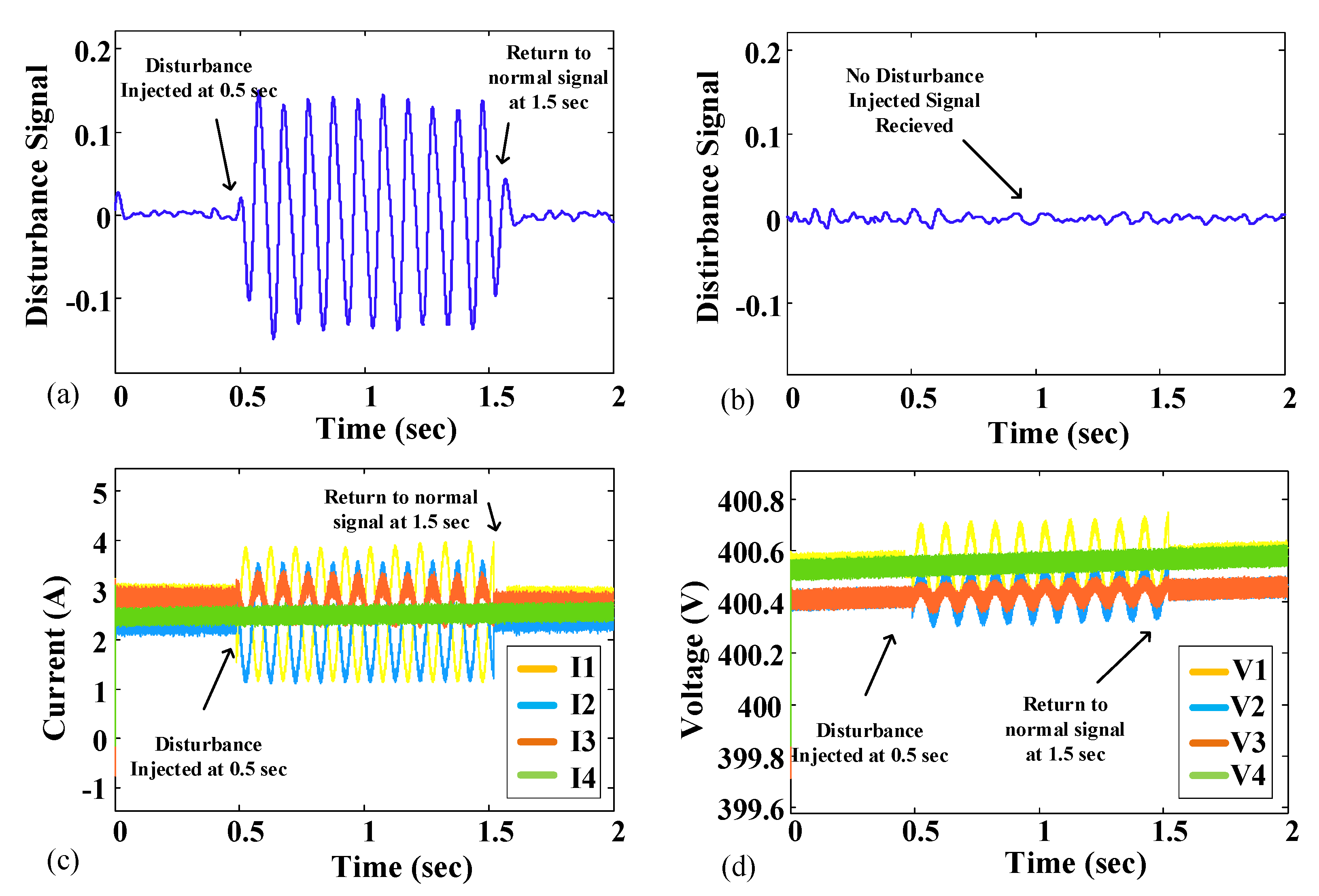
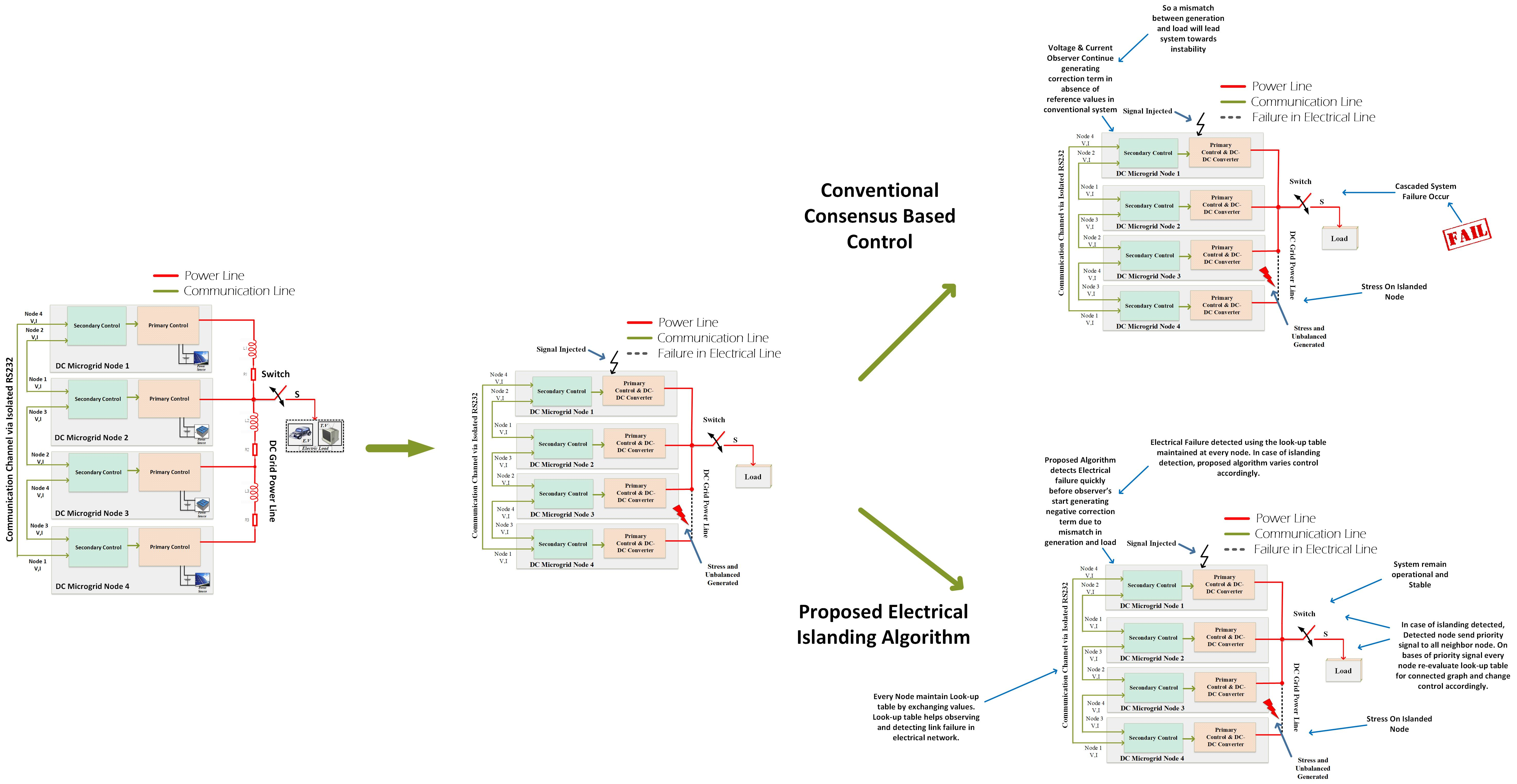
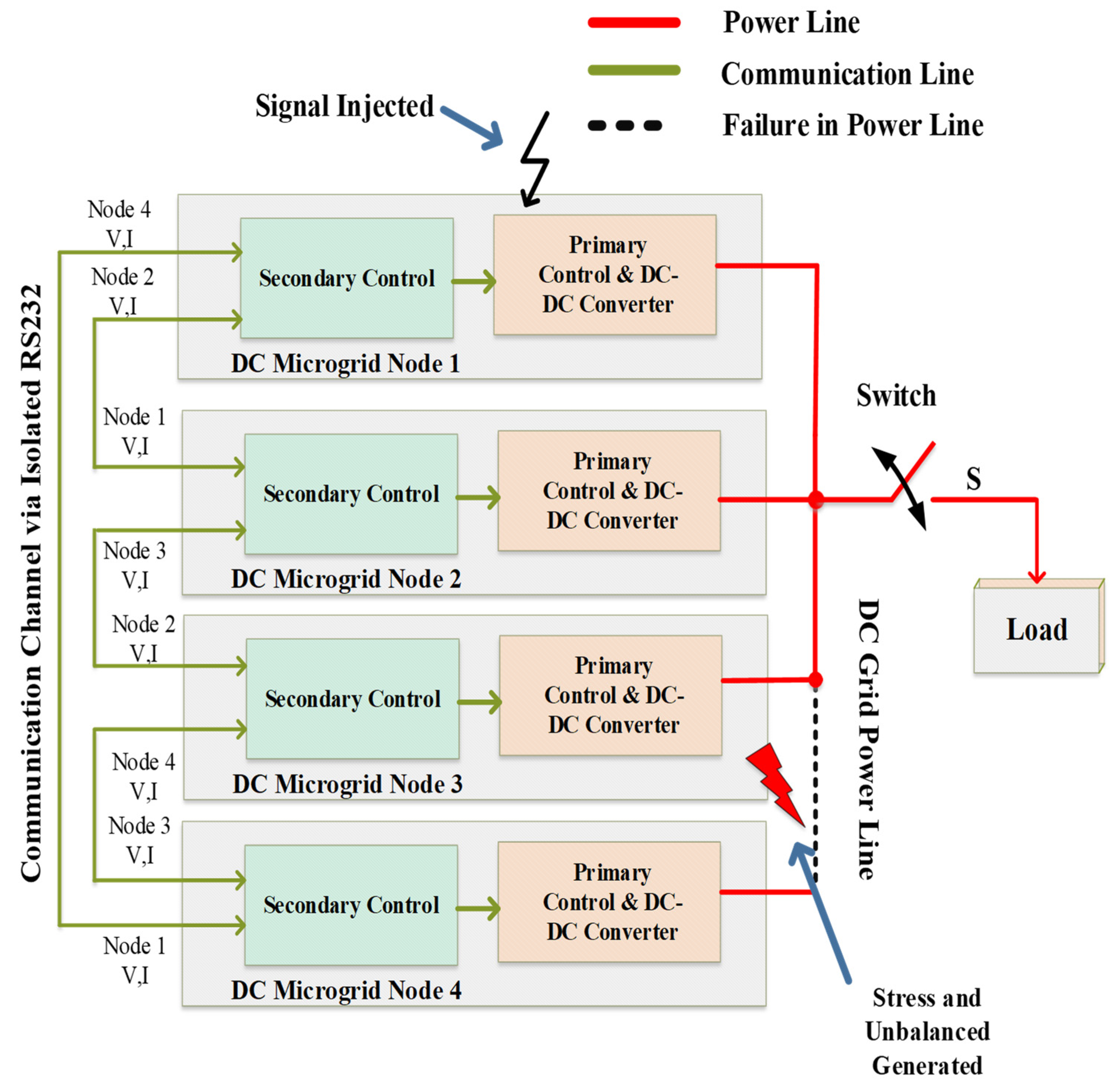
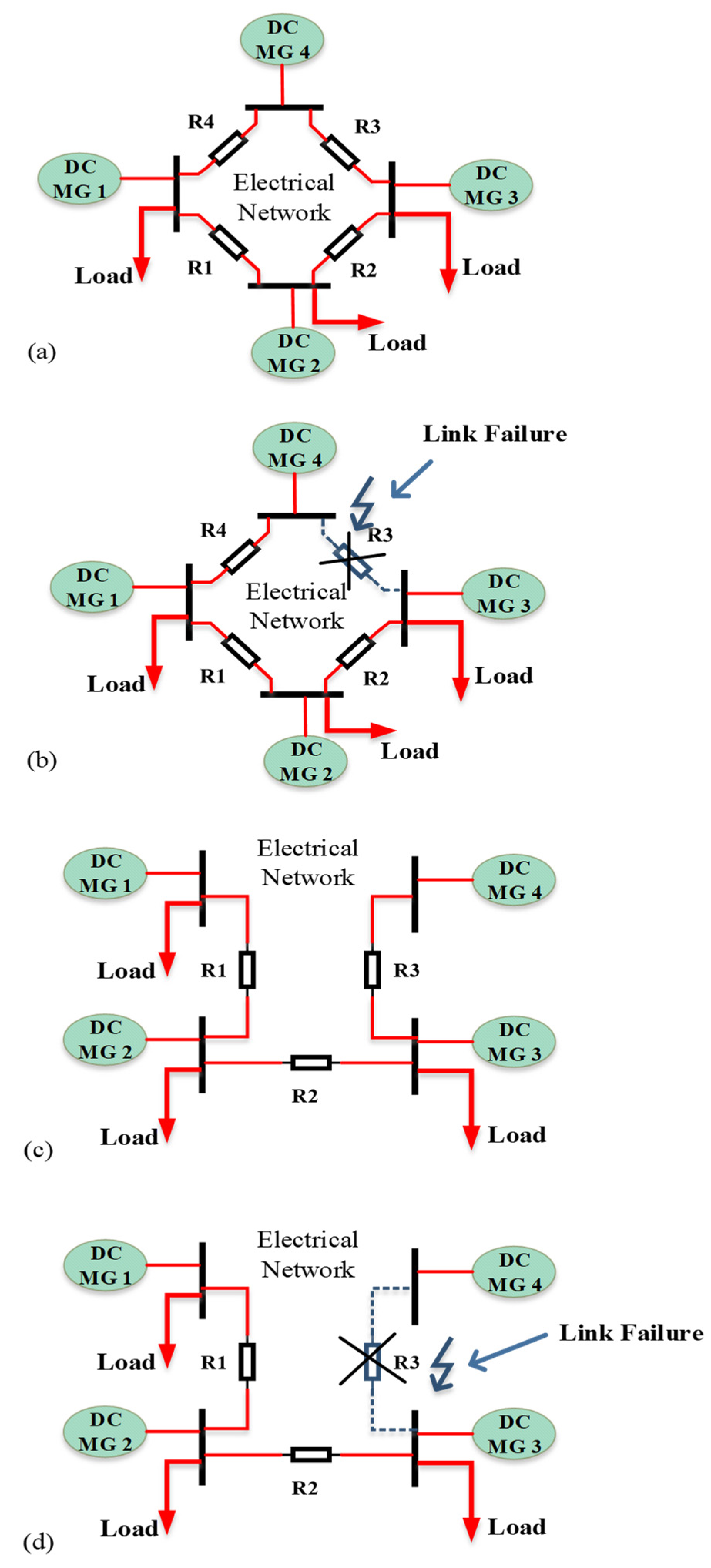
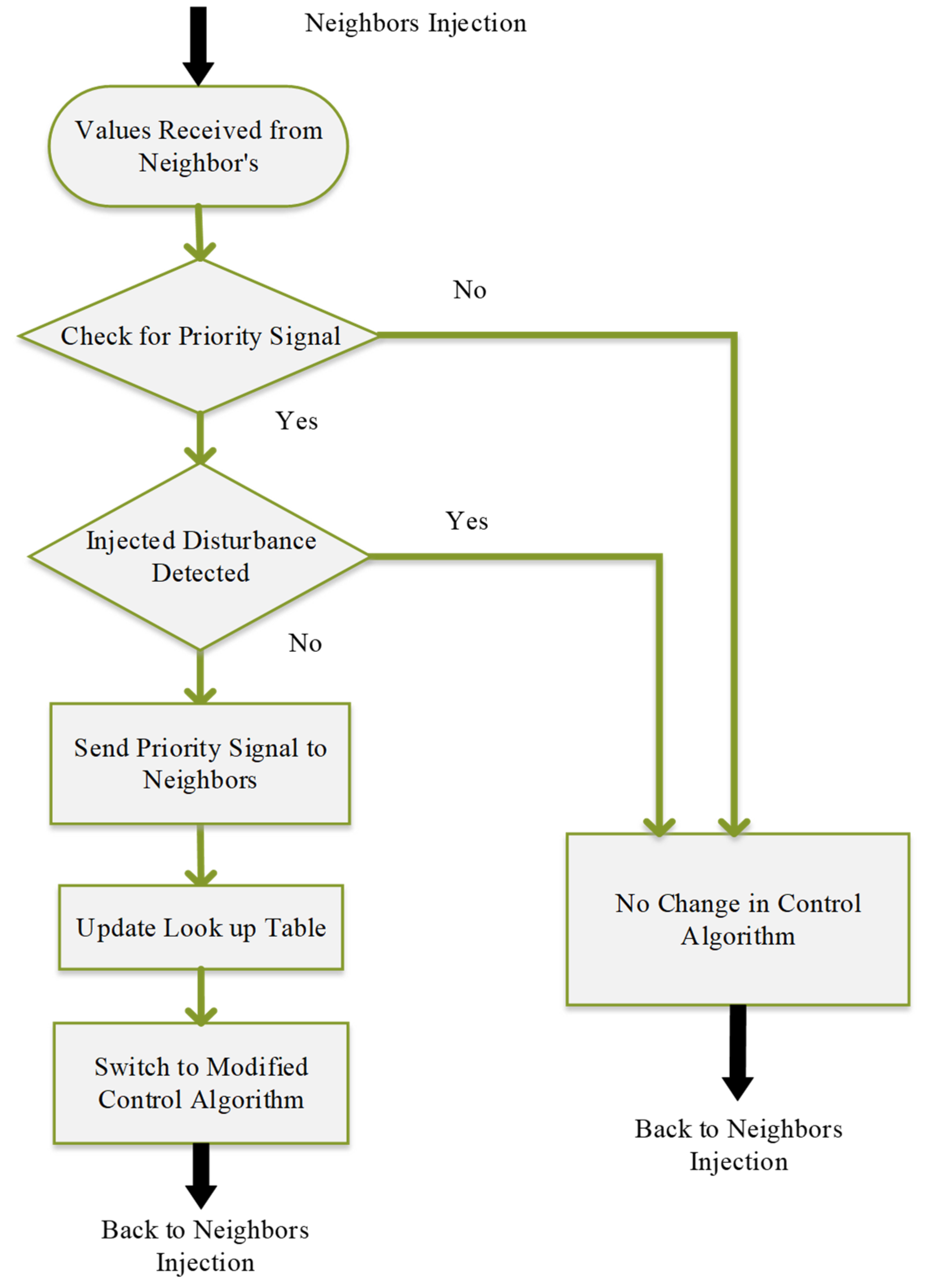
  • Every node can inject disturbance to check the electrical network connectivity. After one node injects disturbance, then other nodes receive disturbance signal, and on that basis detection of islanding occurs.
  • The proposed control has the plug and play capabilities in which DC MG does not require prior information of the agent nodes.
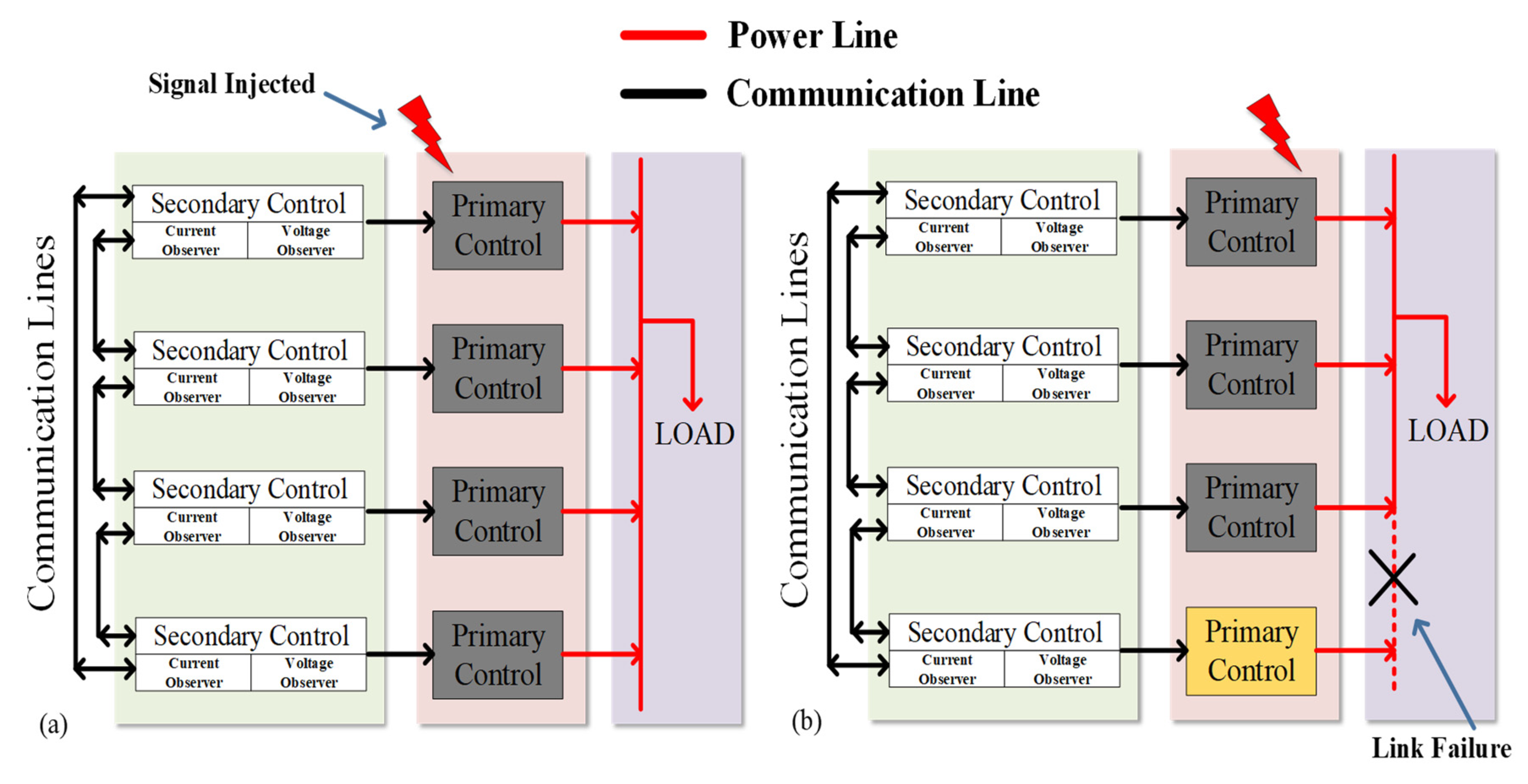
  • Converters can communicate with its neighboring nodes using the sparse communication network spanned across the MG.
  • Electrical network islanding is detected using the existing communication network without adding any more complexity.

2. Detection and Impact of Islanding

Any islanding that occurs within nodes of DC MG network, may form multiple electrical islands as revealed in Figure 1. The proposed method can detect and maintain system operation using the injection-based communication method. An existing communication network is used in the proposed method to share information between MG nodes. Consensus-based algorithm is used for the operation of the MG network. The communication in MG is carried out at secondary level control. Now, we add smartness at secondary level control which can generate the look-up table for the connected nodes. Look-up table can be used to detect any link failure or islanding in the electrical network. If any link failure occurs then the disconnected node sends a priority signal to every connected node in look-up table and each node then reevaluates the look-up table.
Furthermore, detection can be carried out using the injection-based communication network by injecting disturbance signal at one node and receive injected disturbance signal on other nodes. This way islanding can be detected effectively and once islanding is detected then the proposed detection method detects and maintain the operation. By utilizing the received injecting disturbance each node generates a connected network look-up table. If islanding occurs then the system can de-energize due to a mismatch between generating unit and load side, so the detection should be quick enough to detect in time to preserve the DC MG operation by modifying network structure. A sparse network is utilized in the proposed control to detect islanding as illustrated in Figure 2 and Figure 3. The proposed technique has the advantage to utilize the same sparse communication network for electrical islanding detection without adding any additional cost for separate devices. By utilizing the sparse network problem is expressed graphically. So, this way proposed control utilized the active and communication-based islanding technique concept for detection of the electrical network.

3. Motivation of Electrical Islanding Detection in DC Microgrid

3.1. Electrical Islanding Motivation of DC System

Replacement of DC network ended up being less complex because of the stunning approach for the innovation semiconductor, and the constant improvement in the field of power electronic converters. Moreover, there are a few additional legitimate purposes behind reevaluating of DC network. These purposes can be categorized as the utility load, RE-based sources, and storage components [11].

3.1.1. DC Utility Load

These days, numerous customers utilize DC-based loads. Electronic-based appliances, increasingly effective lightning innovations. Variable Speed Drives are utilized for air conditioning, heating, pumping and ventilation fans, lifts, factories, and traction systems. Similarly, applications in the industry such as the steel industry is very commonly utilizing more and more DC electric furnaces, due to their less power consumption than their comparing AC counterparts. Data Server farms are commonly outfitted with an un-interrupted power supply (UPS), it requires different conversion stages to connect the battery and DC bus line. If the power is transmitted in the DC system, then the losses due to multiple conversion stages can be reduced [11].

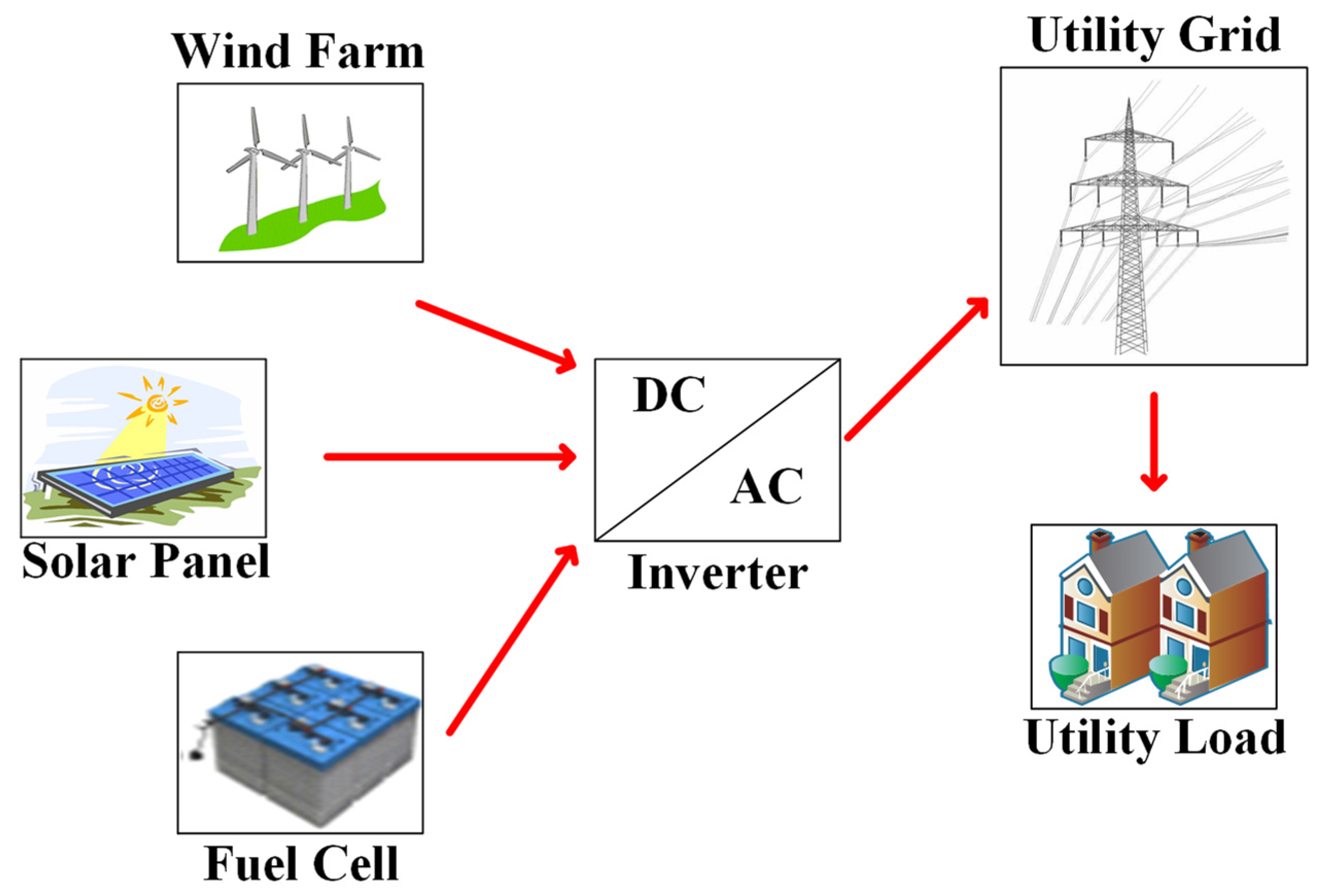
3.1.2. RE Based Sources

Encouraged by ecological and financial conditions, more and more people for moving towards the utilization of RE-based solutions. Some of the RE-based sources are DC generating sources (e.g., Photo Voltaic, fuel cells). In the circumstances of a wind turbine, the AC network is coordinated through a DC inter-link, changing over the distribution network to DC can dispose of a conversion stage and therefore improves efficiency. Smaller-scale micro-turbines generate AC power with high frequency, which is simpler to associate with a DC network [11].

3.1.3. Storage Sources

The primary advantage of the DC network system is its inherited capability to enable static charge storage. Storage sources are DC, e.g., batteries, etc. Depending on the previous literature, a DC power supply is more reliable than an AC un-interruptible power supply.

3.2. Islanding Detection Motivation

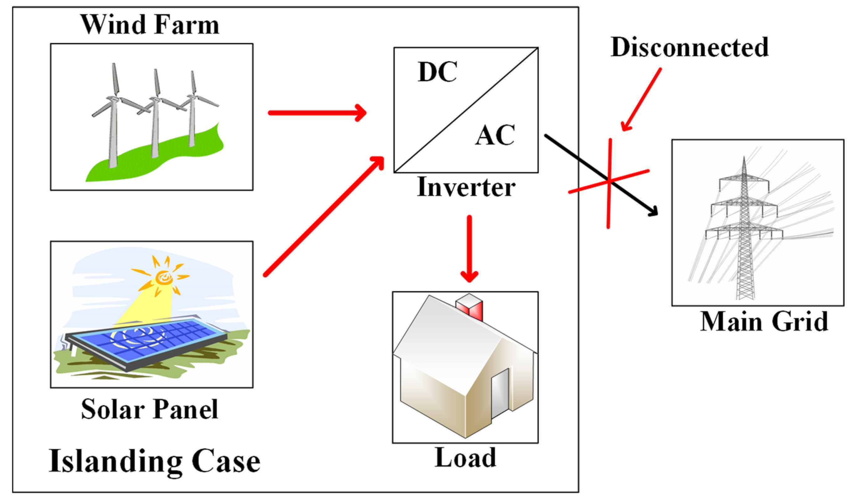
3.2.1. Islanded Operation

During a fault, the protection equipment that is adjacent to the fault location will respond and secure the rest of the power system. In this way, just the distributed RE-based sources will supply the energy for the utility demand. Normally, the energy provided by distributed RE-based sources are not sufficient for the utility demand. Thus, the situation affects the system parameter values, then the threshold values. Additionally, in an unprecedented event, the generation by the distributed RE-based sources are sufficient to meet the demand of all utility demand in the islanded case. Finally, when the distributed RE-based sources provide the load demands afterwards the separation from the grid network, this state is called islanding.

3.2.2. Islanded Phenomenon

After distributed RE-based sources have been isolated from the main grid, then this condition proceeds and raise some issue. Islanding causes numerous issues, some of which are recorded underneath:
  • Safety Concern
Fundamental concern in the electric network is safety, as the grid may in any case be energized in the occurrence of a blackout because of power provided by distributed RE-based sources. This may confound the utility professionals and expose them to the danger of acquiring a shockwave.
  • Consumer’s Appliances Damages
Due to islanding in RE-based generation, there may be a bi-directional progression of power. It might create serious harm to electrical gear, apparatuses, and appliances. A few loads are more delicate to voltage variances than others and should be connected with surge protection devices all the time.
  • Damage to Inverters
In the situation of a larger PV network, load demand is met by installing multiple conversion stages. In the case of islanding, inverters operation can be affected due to islanding.
  • Restoration Delay
If the islanding scenario has proceeded persistently in the electrical network, the restoration from the fault will take time because of the asynchronous operation of the protection devices.
In this case, RE-based production should be disconnected from the system to avoid the above discussed scenarios. It can be achieved by utilizing islanding detection.

4. Detection Methods (IDMs)

Traditionally, the IDMs can be categorized into two parts: one way is local detection schemes and the second is the remote detection scheme [13,34,35]. Where, local Detection schemes involve passive detection and active detection schemes as well. These schemes are presented in Table 1 and Table 2.

4.1. Detection Using Passive Scheme

Passive detection method working is totally dependent on the setting of the threshold level. Islanding detection can be carried out by detecting variation in the nominal values. The main advantage of this method includes easiness to implement, the high computational controller is not required, no effect on the power system in the form of power quality, short time required to detect, and low cost is required to achieve and maintain. The drawbacks of this method include the large size of the non-detection zone, which makes it in-efficient in the multiple inverter network [36,37]. The parameters mostly used to detect islanding using the passive method are over/under voltage, over/under frequency, total harmonic distortion, harmonics in voltage, harmonics in current, and phase shift in voltage.

4.2. Detection Using Active Scheme

In the active detection method, the detection of the islanding event is better than the passive detection method. It can detect the islanding event using the injection of a small disturbance signal at the inverter output terminal. Using the disturbance signal injection, the active detection method calculates the impedance using voltage and current measured from the generation side terminal. In the case of normal operation, the impedance is very small. Therefore, the active detection method has a very small non-detection zone which makes it more effective in comparison to the passive detection method. However, there are few drawbacks in the active detection method such as long-time required to detect islanding events, affect the power systems in the form of power quality, computational controller is required, complex network control, and high cost to implement.

4.3. Detection Using Remote Method
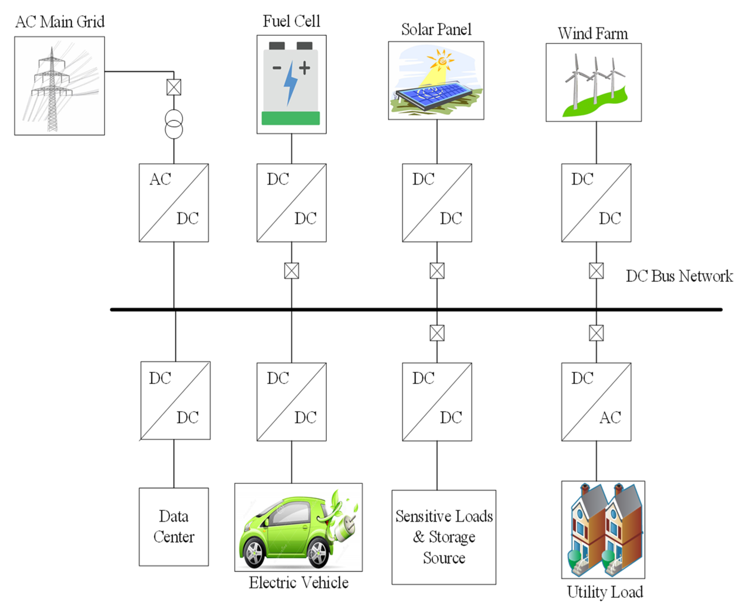
Remote detection islanding method is dependent on the information exchange between power system equipment. Information exchange includes status of the protection equipment such as circuit breakers. This status information is then used to check and detect the islanding on that basis send the indication to the CB (circuit breaker) to trip and detach the power system connectivity. This detection method has an advantage such as a very short time interval to detect islanding, no effect on the power system in the form of power quality, does not include any non-detection zone. The drawbacks in this detection method include very high cost for implementation, complicated and complex control, high computational control required to collect information and process.

4.4. DC Network

In the DC network system as shown in Figure 4, there are few limitations and drawbacks because of the un-availability of the frequency parameter, the only voltage measured at the point of common coupling, which can be further used to detect islanding. However, DC system required some special methods to detect islanding as compared to its counterpart AC system. In recent studies, very few research is carried out for the DC system in the case of islanding detection. An islanding detection technique is used for the hybrid network, in which the voltage and frequency defection and variation on the AC side to DC side is used to detect the islanding by utilizing the DC-DC converter. This technique was tested variously on different scenarios. However, this study was mostly on AC side for islanding detection rather than DC system. Furthermore, due to the disturbance on the AC side frequency or voltage affecting the DC side voltage, so the effectiveness of the islanding detection method is limited [19].
For DC network, an islanding detection method is used by combining the passive and active islanding detection methods. This method’s basic principle is to utilize current perturbation as an injected signal to create an imbalance in the network for a certain amount of time at a specific frequency and observe the system behavior. This detection method is based on the MPPT algorithm, perturb and observation (P&O) [20]. Positive feedback islanding technique based on the active islanding detection method is presented in [18,38]. This method is studied to minimalize the NDZ in the worst case scenario such as the demand load side matches with the generation capacity of the distributed RE-based sources. The islanding detection in this technique is achieved using the variation in voltage from their regular values by injecting a disturbance signal.

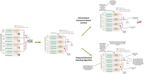
5. Electrical Network Islanding Detection Algorithm

5.1. Representation of the Network

To analyze and represent the system in mathematical formation graph theory can be utilized for electrical networks same as communication networks. So, this way system can be presented in mathematical terms and analyzed for electrical network islanding and if any islanding occurs then the system can detect and preserve system operation.
Connected edges with vertices i and j are represented as j i , i j . Agent nodes of the MG are taken as vertices and denoted by V G = [ V 1 g , V 2 g , V 3 g V N g ] and edges can be represented by E G   V G × V G . This technique generates the loop and cut set matrix using the Laplacian matrix. Adjacency matrix can be represented as A G = | a i j |     R N × N .
| A G | i j = { 1                 i f   v i v j E , 0               O t h e r w i s e .
Data shared between neighboring nodes generate degree matrix, in-degree matrix D G i n = d i a g   { d i i n } , d i i n = j     N i a j i and out-degree matrix D G o u t = d i a g   { d i o u t } , d i o u t = i     N i a j i [39].
D G = [ d ( v 1 ) 0 0 d ( v N ) ]
Removal of an edge from a connected graph or node may affect the connectivity of the graph or nodes is called Cut set. If the vertex is denoted by V of G and if the subset of vertices is denoted by P in one component of G induced by cut set, then ( P , P ¯ ) represents the cut set, where P ¯ = V P . Dimension of the n vertices for Cut set space of a graph is ( n 1 ) . By utilizing these, the final Laplacian matrix will be denoted as L G [40,41,42].
L G = D G A G
L G = [ d ( v 1 ) 0 0 d ( v N ) ] [ a i i a i N a N i a N N ]

5.2. Proposed Islanding Detection

As an example, a distributed consensus-based DC MG is considered in Figure 5. All the nodes exchange information for better load sharing. Detection of the islanding can be achieved by maintaining information on nodes about the electrical network connectivity of the nodes as shown in Equation (5). Every node has the capability of injecting a distributed signal and receive distributed signal to check the connectivity. At the time of signal injection at node 1, it also transmits a signal using a communication network about disturbance signal injection. So, each node checks and receives a disturbance signal to check the connectivity. By utilizing this information each node generates a look-up table for electrical connectivity. If the distributed signal is received then the system is considered as connected, but if no injected disturbance then an islanding event occurs in the electrical network. This way islanding method detects islanding events well in time and preserves the operation of the load demand.
As shown in Figure 5b,c a link failure is detected in the network, then the proposed method modifies the control structure to balance the difference between generating nodes and load nodes. This can be realized in Equation (6) for single link failure and multiple islands formed as shown in Figure 5d, then node 1 to node 3 is connected and operational which can be realized as in Equation (7). After detection, the system modifies the network structure to maintain supplying the load. Modification involves the opening of the protective devices so the system can manage load and generation as this can be seen in Figure 5.
L G = [ d ( v 1 ) 0 0 d ( v 2 ) 0                 0 0                 0 0                 0 0                 0 d ( v 3 ) 0 0 d ( v 4 ) ] [ a 11 a 12 a 21 a 22 a 13 a 14 a 23 a 24 a 31 a 32 a 41   a 42 a 33 a 34 a 43 a 44 ]
L G = [ d ( v 1 ) 0 0 d ( v 2 ) 0                 0 0                 0 0                 0 0                 0 d ( v 3 ) 0 0 d ( v 4 ) ] [ a 11 a 12 a 21 a 22 a 13 a 14 a 23 a 24 a 31 a 32 a 41   a 42 a 33 0 0 a 44 ]
L G = [ d ( v 1 ) 0 0 0 d ( v 2 ) 0 0 0 d ( v 3 ) ] [ a 11 a 12 a 13 a 21 a 22 a 23 a 31 a 32 a 33 ]
The model proposed is used to detect islanding by utilizing the communication network information. DC MG used a sparse network to share information to regulate voltages and load sharing. Using the same communication network, the proposed technique can detect the electrical islanding within nodes and maintain system operation during faults. The proposed system utilized an injection-based disturbance signal to detect and check the connectivity of the nodes. Every node can inject a signal and detect the signal at primary level control. If any link failure is detected then the information is shared with the neighbor nodes. So, every node then updates its look-up table of electrical connectivity. This way system detects the electrical islanding but the system still converges to common reference in the case of different electrical islands. This way system energizes the load without system shutdown. A flow chart of the proposed detection technique is presented in Figure 6.

5.3. DC MG System Modeling
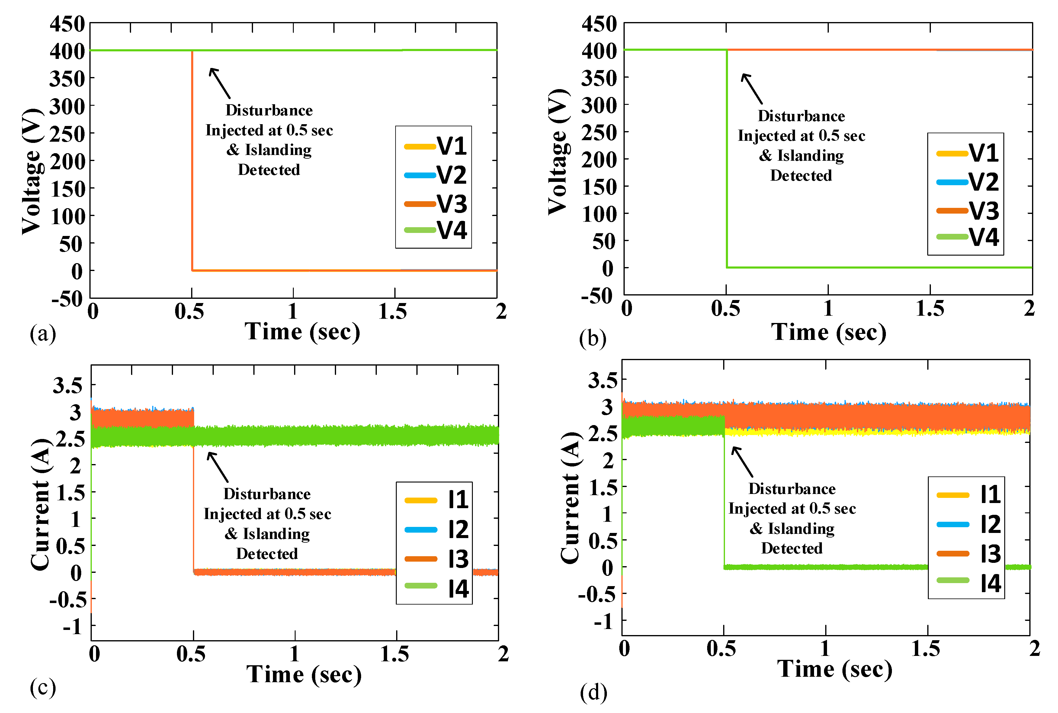
Let global reference voltage vector v r e f = [ v 1 r e f , . , v n r e f ] T and i = [ i 1 , i n ] T is the current vector. The cooperative control generates δ v 1 and δ i i . δ i i is denoted as δ v 2 [43,44]. Δ v 1 = [ δ v 1 1 , . , δ v N 1 ] T and Δ v 2 = [ δ v 1 2 , . , δ v N 2 ] T are voltage and current correction vectors. The Laplace transforms of Δ v 1 and Δ v 2 are Δ V 1 and Δ V 2 . Accordingly,
Δ V 1 = H ( V r e f V ¯ )
Δ V 2 = c G L I P U
The voltage controller matrix is represented as, H = d i a g { H i } and the current controller matrix is represented as G = d i a g { G i } . Where C is the conversion factor whose value can be modeled based on network parameters. The Laplace transform of i P U is I P U , which is the per-unit current vector i P U = [ i 1 P U , i N P U ] T .
Per unit of the current ( I P U ) can be calculated as:
I P U = I r a t e d 1 I
where I r a t e d 1 is the rated current and I is the actual current. The suggested controller’s local voltage set point is,
V * = V r e f + Δ V 1 + Δ V 2 r I
V * = ( I N + H ) V r e f + H V ¯ ( c G L I r a t e d 1 + r ) I
The vector of the local voltage set is v * and V * is its Laplace transform, and the virtual resistance matrix is r. Where V = G i c V i * can be used to represent the dynamic behavior of a closed-loop converter. V i and V i * are the voltage and G i c is the gain of converter i. The transfer matrix is G c = d i a g { G i c } . By substituting values in Equation (12),
V = G c ( ( I N + H ) V r e f + H V ¯ ( c G L I r a t e d 1 + r ) I )
By reorganizing, we can acquire,
V ¯ = s ( s I N + L ) 1 V = H o b s V
Assume the neighbor’s reference voltages have a periodic delay ( τ ).
V ¯ = s ( s I N + L ) 1 V = H o b s V e s τ
This function will be stable for a period of time. The admittance Y b u s matrix is based on the actual current provided ( I = Y b u s V ). The admittance matrix contains all the detail about the distributed grid. Therefore, the system can be presented as:
{ V = ( G c 1 + H H o b s F × e s τ + ( c G L I r a t e d 1 + r ) Y b u s ) 1   ( I N + H ) V r e f I = ( ( Y b u s G c ) 1 + H H o b s F Y b u s 1 × e s τ + c G L I r a t e d 1 + r ) 1   ( I N + H ) V r e f

6. Case Study

A circular bi-directional communication ring is considered for an experimental case study which can be ring or radial on the electrical network side. For the considered study DC MG has 4 nodes system with radial or ring-shaped network to energize the load (resistive) attached to DC MG nodes. An isolated RS232 communication channel was utilized in the case study to transfer information, channel transmission delay was also considered in the case study. A detailed switch model of power converters was utilized in the case study for more realistic outcomes.
Figure 3 and Figure 7 show the full case scenario, and Table 3 shows the detailed node parameters utilized for the case study. All the line impedance was also considered in the case study. Case study setup is considered these all conditions to verify the efficacy of the proposed detection technique by carrying out simulations in MATLAB/Simulink.
The proposed method can sense the electrical network islanding within nodes as shown in Figure 8, which can lead to the MG imbalance between generation and demand and eventually shut down the total system. To avoid, such cases the system can be efficient to detect and maintain system operation well in time. To detect islanding each node can inject a disturbance signal as shown in Figure 8a.
After detection of the islanding, the proposed system remains stable and operates within range. Figure 7a shows the fully connected balanced Laplacian matrix for the ring-shaped network as shown in Equation (17):
L G = [ 2 1 1 2 0 1 1 0 0 1 1 0 2 1 1 2 ]
By utilizing this information each node generates its look-up table for electrical network connectivity. However, if any node did not receive the disturbance signal at the time of injection, then this node will be considered disconnected. Then disconnected node sends the priority signal to its neighbor nodes using the existing communication network. After receiving the priority signal, the look-up table is re-evaluated on each node for the connected nodes. In addition, after detect of the islanding every node checks its parameters for imbalance in power generation and supply-demand. If in any case, an imbalance occurs then the protection system is activated and maintains system operation by disconnecting the extra load circuit breaker. If all the node receives the disturbance signal at the time of injection, then nodes are considered as connected. This way each node generates a look-up table for the connected graph. In case of any node does not receive a disturbance signal, then the MG nodes check the connected graph look-up table and detect the disconnected nodes as shown in Figure 8b–d. This way look-up table will be calculated again after sharing the information regarding the disconnected node. The updated look-up is shown in Figure 9a,c for the remaining connected nodes and for the disconnected nodes look-up table is shown in Figure 9b,d and also shown in Table 4. Figure 5 and Figure 7 shows the case study scenarios.
Similarly, one link failure is considered which affects the Laplacian matrix as shown in Figure 7b and Equation (18). In contrast, Equation (19) shows new Laplacian matrix in the case of both links failure occurred:
L G = [ 1 1 1 2 0 1 0 0 0 0 1 0 2 1 1 1 ]
L G = [ 1 1 0 1 0 2 1 1 1 ]
whereas, Figure 5c shows the fully connected balanced Laplacian matrix for the radial shaped network as shown in Equation (20):
L G = [ 1 1 1 2 0 1 0 0 0 0 1   0 2 1 1 1 ]
Similarly, Figure 5d shows the scenario for one link failure in which case the Laplacian matrix is updated as represented in Equation (21) and this can also be seen in look-up graphs Figure 9 and Table 4.
L G = [ 1 1 0 1 0 2 1 1 1 ]
The proposed method has plug and play capability because DC MG does not need prior information regarding the number of nodes. If simply one node is added I the network then the neighbour node adjusts the operation accordingly. This way this proposed control manages to have plug and play property.

7. Comparison Study with Existing Control Techniques

The proposed electrical network islanding detection control algorithm is designed to detect the physical islanding in the electrical network. Electrical network islanding should be fast enough to detect islanding rapidly and manage the load well in time. In comparison with the conventional detection control methods such as passive, active, and remote detection techniques, the proposed control utilized the active and remote islanding detection scheme concept and injected the signal to detect the islanding by using the communication network. The main drawback of the passive detection technique in comparison with the proposed method, it has a large range of non-detection zone, which makes it less effective. Whereas, the main drawback in the active detection method is its large operating interval to detect and its higher cost. As in the remote detection method, the operating time is short and has no non-detection zone problem, but the drawback in this method is its higher cost. The proposed electrical network does not have a non-detection zone and its cost is lower. It can identify the islanding by injecting a disturbance signal and utilizing the existing communication network in DC MG. These properties make the proposed control more affective and reliable. The detailed comparison table is given in Table 5 [11].

8. Conclusions

An intelligent based islanding detection method is proposed for the DC MG to check the electrical network islanding within nodes. The proposed islanding detection technique identifies the dis-connectivity, and if any dis-connectivity arises, then the proposed technique balances out the DC MG and keeps the operation and load sharing. Detection can be carried out using an injection-based technique and utilizes the existing communication network to check network connectivity. Each node maintains the lookup table for the connected network. This lookup table is used for the detection of the islanding/link failure. This research study displays that the proposed islanding detection technique is effective during the islanding scenarios.

Author Contributions

Conceptualization, M.U.S.; methodology, M.U.S. and T.A.; software, A.S.; validation, M.U.S., S.A. and Z.A.; writing—original draft preparation, M.U.S. and Z.A.; writing—review and editing, H.M.M., A.S. and S.A.; visualization, H.M.M. All authors have read and agreed to the published version of the manuscript.

Funding

This research received no external funding.

Institutional Review Board Statement

Not applicable.

Informed Consent Statement

Not applicable.

Data Availability Statement

Not applicable.

Conflicts of Interest

The authors declare no conflict of interest.

References

  1. Merino, J.; Mendoza-Araya, P.; Venkataramanan, G.; Baysal, M. Islanding Detection in Microgrids Using Harmonic Signatures. IEEE Trans. Power Deliv. 2014, 30, 2102–2109. [Google Scholar] [CrossRef] [Green Version]
  2. De Mango, F.; Liserre, M.; Dell’Aquila, A.; Pigazo, A. Overview of Anti-Islanding Algorithms for PV Systems. Part I: Passive Methods. In Proceedings of the EPE-PEMC 2006: 12th International Power Electronics and Motion Control Conference, Portoroz, Slovenia, 30 August–1 September 2006. [Google Scholar]
  3. Wang, D.; Emhemed, A.; Burt, G. A Novel Protection Scheme for an LVDC Distribution Network with Reduced Fault Levels. In Proceedings of the 2017 IEEE 2nd International Conference on Direct Current Microgrids (ICDCM 2017), Nuremburg, Germany, 27–29 June 2017; pp. 69–75. [Google Scholar]
  4. Saleh, K.A.; Hooshyar, A.; El-Saadany, E.F. Ultra-High-Speed Traveling-Wave-Based Protection Scheme for Medium-Voltage DC Microgrids. IEEE Trans. Smart Grid 2017, 10, 1440–1451. [Google Scholar] [CrossRef]
  5. Makkieh, A.; Florida-James, A.; Tzelepis, D.; Emhemed, A.; Burt, G.; Strachan, S.; Junyent-Ferre, A. Assessment of Passive Islanding Detection Methods for DC Microgrids. In Proceedings of the 15th IET International Conference on AC and DC Power Transmission (ACDC 2019), Coventry, UK, 5–7 February 2019; pp. 1–6. [Google Scholar]
  6. De Mango, F.; Liserre, M.; Dell’Aquila, A.; Pigazo, A. Overview of Anti-Islanding Algorithms for PV Systems. Part II: Active Methods. In Proceedings of the EPE-PEMC 2006: 12th International Power Electronics and Motion Control Conference, Portoroz, Slovenia, 30 August–1 September 2006; pp. 1884–1889. [Google Scholar]
  7. Sultana, B.; Mustafa, M.; Sultana, U.; Bhatti, A.R. Review on Reliability Improvement and Power Loss Reduction in Distribution System via Network Reconfiguration. Renew. Sustain. Energy Rev. 2016, 66, 297–310. [Google Scholar] [CrossRef]
  8. Emhemed, A.A.S.; Fong, K.; Fletcher, S.; Burt, G. Validation of Fast and Selective Protection Scheme for an LVDC Distribution Network. IEEE Trans. Power Deliv. 2016, 32, 1432–1440. [Google Scholar] [CrossRef] [Green Version]
  9. Mirsaeidi, S.; Dong, X.; Shi, S.; Tzelepis, D. Challenges, Advances and Future Directions in Protection of Hybrid AC/DC Microgrids. IET Renew. Power Gener. 2017, 11, 1495–1502. [Google Scholar] [CrossRef] [Green Version]
  10. Khadem, S.K.; Basu, M.; Conlon, M.F. Intelligent Islanding and Seamless Reconnection Technique for Microgrid With UPQC. IEEE J. Emerg. Sel. Top. Power Electron. 2014, 3, 483–492. [Google Scholar] [CrossRef]
  11. Son, T.T.; Fujita, G. Islanding Detection in DC Network. In Proceedings of the 52nd International Universities Power Engineering Conference (UPEC), Heraklion, Greece, 29 August–1 September 2017. [Google Scholar]
  12. Paz, F.; Ordonez, M. An Impedance-Based Islanding Detection Method for DC Grids. In Proceedings of the 2018 9th IEEE International Symposium on Power Electronics for Distributed Generation Systems (PEDG), Charlotte, NC, USA, 25–28 June 2018; IEEE: Piscataway, NJ, USA, 2018; pp. 1–7. [Google Scholar]
  13. Seo, G.; Baek, J.; Choi, K.; Bae, H.; Cho, B. Modeling and Analysis of DC Distribution Systems. In Proceedings of the 8th International Conference on Power Electronics—ECCE Asia, Jeju, Korea, 30 May–3 June 2011; IEEE: Piscataway, NJ, USA, 2011; pp. 223–227. [Google Scholar]
  14. Bansal, Y.; Sodhi, R. Microgrid Fault Detection Methods: Reviews, Issues and Future Trends. In Proceedings of the IEEE Innovative Smart Grid Technologies—Asia (ISGT Asia), Singapore, 22–25 May 2018; pp. 401–406. [Google Scholar] [CrossRef]
  15. Sannino, A.; Postiglione, G.; Bollen, M. Feasibility of a DC Network for Commercial Facilities. In Proceedings of the Conference Record of the 2002 IEEE Industry Applications Conference. 37th IAS Annual Meeting (Cat. No.02CH37344), Pittsburgh, PA, USA, 13–18 October 2002. [Google Scholar] [CrossRef]
  16. Ghareeb, A.T.; Mohamed, A.A.; Mohammed, O.A. DC Microgrids and Distribution Systems: An Overview. In Proceedings of the IEEE Power and Energy Society General Meeting, Vancouver, BC, Canada, 21–25 July 2013. [Google Scholar]
  17. Cintuglu, M.H.; Mohammed, O.A. Islanding Detection in Microgrids. In Proceedings of the 2013 IEEE Power & Energy Society General Meeting, Vancouver, BC, Canada, 21–25 July 2013; pp. 1–5. [Google Scholar] [CrossRef]
  18. Mohamad, A.M.I.; Mohamed, Y.A.-R.I. Assessment and Performance Comparison of Positive Feedback Islanding Detection Methods in DC Distribution Systems. IEEE Trans. Power Electron. 2016, 32, 6577–6594. [Google Scholar] [CrossRef]
  19. Papadimitriou, C.N.; Kleftakis, V.A.; Hatziargyriou, N.D. A Novel Method for Islanding Detection in DC Networks. IEEE Trans. Sustain. Energy 2016, 8, 441–448. [Google Scholar] [CrossRef]
  20. Seo, G.-S.; Lee, K.-C.; Cho, B.-H. A New DC Anti-Islanding Technique of Electrolytic Capacitor-Less Photovoltaic Interface in DC Distribution Systems. IEEE Trans. Power Electron. 2012, 28, 1632–1641. [Google Scholar] [CrossRef]
  21. Vahedi, H.; Noroozian, R.; Jalilvand, A.; Gharehpetian, G.B. A New Method for Islanding Detection of Inverter-Based Distributed Generation Using DC-Link Voltage Control. IEEE Trans. Power Deliv. 2011, 26, 1176–1186. [Google Scholar] [CrossRef]
  22. Emhemed, A.; Burt, G. The Effectiveness of Using IEC61660 for Characterising Short-Circuit Currents of Future Low Voltage DC Distribution Networks. In Proceedings of the 22nd International Conference and Exhibition on Electricity Distribution (CIRED 2013), Stockholm, Sweden, 10–13 June 2013; Volume 5, pp. 3–6. [Google Scholar]
  23. Haider, R.; Kim, C.H.; Ghanbari, T.; Bukhari, S.B.A.; Zaman, M.S.U.; Baloch, S.; Oh, Y.S. Passive Islanding Detection Scheme Based on Autocorrelation Function of Modal Current Envelope for Photovoltaic Units. IET Gener. Transm. Distrib. 2017, 12, 726–736. [Google Scholar] [CrossRef]
  24. Do, H.T.; Zhang, X.; Nguyen, N.V.; Li, S.S.; Chu, T.T.-T. Passive Islanding Detection Method Using Wavelet Packet Transform in Grid Connected Photovoltaic Systems. IEEE Trans. Power Electron. 2015, 31, 1. [Google Scholar] [CrossRef]
  25. Link, C.; Zeineldin, H.H.; Kirtley, J.L. Performance of the OVP/UVP and OFP/UFP Method with Voltage and Frequency Dependent Loads. IEEE Trans. Power Deliv. 2013, 24, 772–778. [Google Scholar]
  26. Dou, C.X.; Liu, B. Multi-agent based hierarchical hybrid control for smart microgrid. IEEE Trans. Smart Grid 2013, 4, 771–778. [Google Scholar] [CrossRef]
  27. Gill, S.; Dolan, M.; Emhemed, A.; Kockar, I.; Barnacle, M.; Ault, G.; Mathieson, C. Increasing Renewable Penetration on Islanded Networks through Active Network Management: A Case Study from Shetland. IET Renew. Power Gener. 2015, 9, 453–465. [Google Scholar] [CrossRef] [Green Version]
  28. Tzelepis, D.; Dysko, A.; Booth, C. Performance of Loss-Of-Mains Detection in Multi-Generator Power Islands. In Proceedings of the 13th International Conference on Development in Power System Protection 2016 (DPSP), Edinburgh, UK, 7–10 March 2016; pp. 1–6. [Google Scholar]
  29. Mohamad, A.M.I.; Mohamed, Y.A.-R.I. Analysis and Mitigation of Interaction Dynamics in Active DC Distribution Systems with Positive Feedback Islanding Detection Schemes. IEEE Trans. Power Electron. 2017, 33, 2751–2773. [Google Scholar] [CrossRef]
  30. Kleftakis, V.A.; Lagos, D.T.; Papadimitriou, C.N.; Hatziargyriou, N.D. Seamless Transition between Interconnected and Islanded Operation of DC Microgrids. IEEE Trans. Smart Grid 2017, 10, 248–256. [Google Scholar] [CrossRef]
  31. Voglitsis, D.; Papanikolaou, N.; Kyritsis, A. Incorporation of Harmonic Injection in an Interleaved Flyback Inverter for the Implementation of an Active Anti-Islanding Technique. IEEE Trans. Power Electron. 2016, 32, 8526–8543. [Google Scholar] [CrossRef]
  32. Kashyap, G.; Ambika, G. Link Deletion in Directed Complex Networks. Phys. A Stat. Mech. Its Appl. 2018, 514, 631–643. [Google Scholar] [CrossRef] [Green Version]
  33. Park, J.-D.; Candelaria, J.; Ma, L.; Dunn, K. DC Ring-Bus Microgrid Fault Protection and Identification of Fault Location. IEEE Trans. Power Deliv. 2013, 28, 2574–2584. [Google Scholar] [CrossRef]
  34. Funabashi, T.; Member, S.; Koyanagi, K.; Yokoyama, R. A Review of Islanding Detection Methods for Distributed Resources. In Proceedings of the 2003 IEEE Bologna PowerTech Conference Proceeding, Bologna, Italy, 23–26 June 2003; p. 6. [Google Scholar]
  35. Starke, M.; Member, S.; Tolbert, L.M.; Member, S. AC vs. DC Distribution: A Loss Comparison. In Proceedings of the 2008 IEEE/PES Transmission and Distribution Conference and Exposition, Chicago, IL, USA, 21–24 April 2008. [Google Scholar]
  36. Syamsuddin, S.; Rahim, N.; Krismadinata; Selvaraj, J. Implementation of TMS320F2812 in Islanding Detection for Photovoltaic Grid Connected Inverter. In Proceedings of the 2009 International Conference for Technical Postgraduates (TECHPOS), Kuala Lumpur, Malaysia, 14–15 December 2009; pp. 1–5. [Google Scholar] [CrossRef]
  37. Ganivada, P.K.; Jena, P. Passive Islanding Detection Techniques Using Synchrophasors for Inverter Based Distributed Generators. In Proceedings of the 2019 IEEE PES GTD Grand International Conference and Exposition Asia (GTD Asia), Bangkok, Thailand, 20–23 March 2019; IEEE: Piscataway, NJ, USA, 2019; pp. 747–751. [Google Scholar]
  38. Zhou, B.; Cao, C.; Li, C.; Cao, Y.; Chen, C.; Li, Y.; Zeng, L. Hybrid Islanding Detection Method Based on Decision Tree and Positive Feedback for Distributed Generations. IET Gener. Transm. Distrib. 2015, 9, 1819–1825. [Google Scholar] [CrossRef]
  39. Habibi, D.; Phung, Q.V. Graph Theory for Survivability Design in Communication Networks. In New Frontiers in Graph Theory; Intech Limied: London, UK, 2012; pp. 421–434. ISBN 9789535101154. [Google Scholar]
  40. Lewis, F.L.; Zhang, H.; Hengster-Movric, K.; Das, A. Cooperative Control of Multi-Agent Systems, 1st ed.; Springer: London, UK, 2014; ISBN 978-1-4471-5573-7. [Google Scholar]
  41. Lee, K.K.-C.; Chen, C.-E. An Eigen-Based Approach for Enhancing Matrix Inversion Approximation in Massive MIMO Systems. IEEE Trans. Veh. Technol. 2016, 66, 5480–5484. [Google Scholar] [CrossRef]
  42. Johnson, C.C.; Demetriades, A.; Locutura, J.; Ottesen, R.T. Mapping the Chemical Environment of Urban Areas; John Wiley & Sons, Ltd.: Hoboken, NJ, USA, 2011; ISBN 9788578110796. [Google Scholar]
  43. Nasirian, V.; Moayedi, S.; Davoudi, A.; Lewis, F.L. Distributed Cooperative Control of DC Microgrids. IEEE Trans. Power Electron. 2014, 30, 2288–2303. [Google Scholar] [CrossRef]
  44. Mesbahi, M.; Egerstedt, M. Graph Theoretic Methods in Multiagent Networks Book; Princeton University Press: Princeton, NJ, USA, 2010. [Google Scholar]
Figure 1. Distributed Renewable Energy (RE) based Generation Network.
Energies 14 08432 g001
Figure 2. Islanding Scenario.
Energies 14 08432 g002
Figure 3. Experimental Setup Considered for the Physical Islanding Detection.
Energies 14 08432 g003
Figure 4. DC Network Structure.
Energies 14 08432 g004
Figure 5. Electrical Network Scenario (a) Ring Type Network, (b) Ring Type Network with Fault, (c) Radial Type Network, (d) Radial Type Network with Fault.
Energies 14 08432 g005
Figure 6. Flow Chart for the Proposed Islanding Detection Method.
Energies 14 08432 g006
Figure 7. Physical Islanding Detection Scenario. (a) without fault; (b) with fault.
Energies 14 08432 g007
Figure 8. Case Study Result (a) Disturbance Signal Received at Every Connected Node, (b) Disconnected Node 4, (c) Node Current, (d) Node Voltages.
Energies 14 08432 g008
Figure 9. DC MG nodes look-up table: (a) Connected Nodes’ Voltage, (b) Disconnected Node 4 Voltage, (c) Connected Nodes’ Current, (d) Disconnected Node 4 Voltages.
Energies 14 08432 g009
Table 1. Local Islanding Detection-Based Schemes.
Local Islanding Detection SchemesList of Detection Methods
Passive Detection MethodUnder/Over Voltage
Voltage Harmonics
Voltage Unbalance
Voltage Phase Shift
Under/Over Frequency
Total Harmonic Distortion
Active Detection MethodImpedance Measurement
Load Fluctuation
Disturbance Signal Injection
Reactive Power Fluctuation
Frequency Bias
Frequency Shift
Voltage Shift
Table 2. Remote Islanding Detection Methods Classification.
Remote Detection MethodList of Detection Techniques
SCADA System
PLC (Power Line Carrier)
Phasor Measurement Unit (PMU)
Disconnect Signal
Table 3. Parameters of each node.
ParametersValues
Input (Vin)600 V
Output (Vo)400 V
G Droop0.025
L1 mH
C300 µF
Load (R)70 ohm
RLine0.0005 ohm/m
LLine0.50 µH/m
Line Length100 m
fSwitching10 kHz
Communication Delay0.15 ms
Gain Inner loopKp = 10
Ki = 0.05
Gain Outer loopKp = 40
Ki = 0.05
V ObserverKp = 6
Ki = 0.1
I ObserverKp = 0.11
Ki = 0.6
Table 4. Look-up table values for simulation results for electrical connectivity.
NodesN1N2N3N4
N10101 Energies 14 08432 i001 0
N21010
N30101 Energies 14 08432 i002 0
N41 Energies 14 08432 i003 001 Energies 14 08432 i004 00
1 Energies 14 08432 i005 0 shows the dis-connectivity of the nodes.
Table 5. Comparison between Islanding Detection Methods (IDMs).
Sr. No.ParametersPassiveActiveRemoteProposed Method
1Principle OperationObserve and Measure the change in voltage, frequency, and HarmonicsInject disturbance signal to observe the system responseCommunication signals exchange between Power system components.Communication signals exchange between Connected Nodes
2Operating TimeShort IntervalLong IntervalShort IntervalShort Interval
3Non-Detection Zone (NDZ)Large RangeSmall RangeNoNo
4Effect of the Distribution SystemNoYesNoNo
5Cost AffectiveLowHighHighNo Extra Cost for Implementation of Control
Publisher’s Note: MDPI stays neutral with regard to jurisdictional claims in published maps and institutional affiliations.

