Article

Analysis of Stationary- and Synchronous-Reference Frames for Three-Phase Three-Wire Grid-Connected Converter AC Current Regulators

by
Israel D. L. Costa
1,
Danilo I. Brandao
1,
Lourenço Matakas Junior
2,
Marcelo G. Simões
3 and
Lenin M. F. Morais
1,*
1
Graduate Program in Electrical Engineering, Federal University of Minas Gerais (UFMG), Antônio Carlos 6627, Belo Horizonte 31270-901, MG, Brazil
2
Department of Electrical Energy and Automation, Polytechnic School of the University of São Paulo (USP), Campus São Paulo, São Paulo 05508-010, SP, Brazil
3
Electrical Engineering Department, School of Technology and Innovations, University of Vaasa, 65200 Vaasa, Finland
*
Author to whom correspondence should be addressed.
Energies 2021, 14(24), 8348; https://doi.org/10.3390/en14248348
Submission received: 4 November 2021 / Revised: 2 December 2021 / Accepted: 2 December 2021 / Published: 10 December 2021
(This article belongs to the Topic Power System Modeling and Control)

Abstract

:
The current state of the art shows that unbalance and distortion on the voltage waveforms at the terminals of a grid-connected inverter disturb its output currents. This paper compares AC linear current regulators for three-phase three-wire voltage source converters with three different reference frames, namely: (1) natural (abc), (2) orthogonal stationary (αβ), and (3) orthogonal synchronous (dq). The quantitative comparison analysis is based on mathematical models of grid disturbances using the impedance-based analysis, the computational effort assessment, as well as the steady-state and transient performance evaluation based on experimental results. The control scheme devised in the dq-frame has the highest computational effort and inferior performance under negative-sequence voltage disturbances, whereas it shows superior performance under positive-sequence voltages among the reference frames evaluated. In contrast, the stationary natural frame abc has the lowest computational effort due to its straightforward implementation, with similar results in terms of steady-state and transient behavior. The αβ-frame is an intermediate solution in terms of computational cost.

1. Introduction

Distributed generation is directly related to renewables proliferation that pushes forward with the modernization of power system and, therefore, grid code requirements [1]. On the core of the distributed generator (DG), the voltage source converter (VSC) is the most common structure used in regulating active power injection from renewable sources into the grid [2]. Besides, the DG can concomitantly provide grid-support services with reactive power exchange [3] and harmonic mitigation [4] under challenging conditions of distorted and unbalanced grid voltages. It is well known that unbalance and distortion on the grid voltages impact on the output currents of VSCs [5]. Thus, much research [6,7,8,9,10,11,12,13,14,15,16,17,18,19,20] has focused on improving the stability and performance [6] of grid-connected converters, in which the current controller is a cornerstone of such a system [7,8].
Figure 1 shows a simplified structure of a grid-connected three-phase three-wire converter. Typically, the primary control level uses the cascade control strategy with an outer DC-link voltage loop and an inner current loop, as shown in Figure 2. Many improvements in grid-connected current control were proposed, using linear and non-linear regulators [8,9,10,11], such as: classical proportional-integral (PI) and proportional-resonant (PR) controllers with feedforward [9,10], state feedback controllers, predictive, among others. The most commonly used control for low computational cost grid-tied inverters, such as rooftop photovoltaic, are based on classical linear control because of its simplicity [11]. The PI and PR controllers for three-phase converters can be devised in different reference frames, such as (1) synchronous rotating (dq), (2) orthogonal stationary (αβ), and (3) natural stationary (abc), being the PI controller in dq-frame the most used, followed by PR controller in αβ-frame [12]. The abc-frame is seldom implemented despite not requiring coordinate transformation, easily decoupled, and shows similar results using two PR controllers. It shows that abc-frame implementation is still blurry and represents a gap in the understanding and thorough evaluation of advantages and drawbacks involving AC current regulators in the three reference frames.
The literature shows a comparison of (abc) and (dq) [12], suggesting a dq-frame controller as a useful solution because it achieves zero steady-state error under sinusoidal voltages. Then the literature also shows a comparison of (dq) and (αβ) [13], concluding that stationary control approaches show superior performance in terms of stiffer closed-loop control under distorted and unbalanced grid voltage conditions than rotating frame approaches. However, the αβ-frame depends on coordinate transformation (i.e., Clarke’s transformation). In contrast, the abc-frame approach proposed in [14,15,16] is straightforward in terms of control implementation because it does not rely on any coordinate transformations. The absence of coordinate transformations is appealing for low computational cost applications.
The authors of [17,18] perform a quantitative comparative analysis of linear current controllers for DG applications devised in stationary- and synchronous-reference frames, like [9]. These quantitative analyses are carried out upon the perspective of PQ, power quality, indices and transient performance. They have not performed a comprehensive analysis, because there was no account of the grid voltage disturbances (i.e., unbalance and harmonics) and computational effort assessment as done herein.
The authors of [16,19] propose an optimal method to calculate the gains of linear current controllers, such as PI and PR for synchronous and stationary frames, respectively. They also shown an analysis of the external disturbances considering a feedforward compensation of the back electromotive force (EMF). However, the authors of [16] only have considered sinusoidal EMF for motor drive applications. In [19], the focus is grid-connected single-phase converters, but a thorough analysis of the disturbances under the non-ideal grid has not been done.
Although the state of the art shows quantitative analysis considering PQ indices, a comparison and a throughout analysis considering the three reference frames, i.e., abc, αβ and dq, assessing computational effort and disturbance rejection, has not been reported for current control on DG mission profile. When compared, the works usually do not consider the abc-frame [20]. Herein, the disturbance rejection was computed by the dynamic stiffness (DS) analysis that quantify the capability of a system to reject a disturbance caused by an external source, and it is quantified as the amplitude of the perturbation needed to produce a unit variation in the controlled variable across the frequency spectrum [21,22]. DS analysis is equivalent to output impedance-based analysis when considering VSC in current-controlled mode. Such a figure of merit is used herein because it guarantees a fair comparison between the reference frames, showing in a same graphic that all the controllers are equally sized, and highlighting their performance over a range of frequency.
Thus, this paper performs a meticulous mathematical analysis comparing three linear AC current controllers devised in natural (abc), orthogonal stationary (αβ), and orthogonal synchronous (dq) reference frames applied to grid-tied VSCs under non-ideal grid voltages. The comparison is performed in terms of DS analysis, transient response, and computational effort assessment in a low-cost commercial digital signal processor (DSP).
This paper is organized as follows: Section 2 presents the converter control scheme and the AC current controllers devised in the three reference frames. Section 3 describes the control performance analysis based on output impedance analysis, the steady-state, and transient performance evaluation and computational effort assessment. Section 4 shows the experimental results, and finally Section 5 concludes this paper.

2. Control of Three-Phase Three-Wire Converter

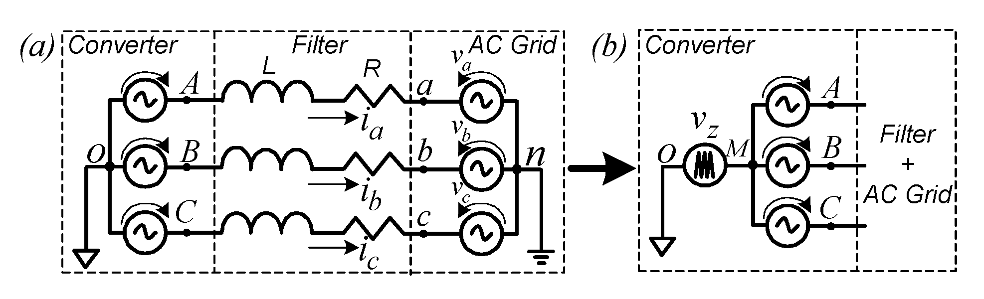
2.1. System Modelling

A current-controlled mode VSC can be simplified by disregarding the grid impedance, Zg, and assuming that the capacitors of the output LC filter do not influence the model up to a frequency range far above the current control bandwidth. The capacitors and grid impedance may affect the current control, but it is neglected herein for the sake of decoupling the external disturbances on the converter output current.
The VSC is modeled by the star connection of three ideal voltage sources (vAO, vBO, vCO) that represent the three legs of a three-phase three-wire converter without split capacitor, connected to the grid through RL filter impedances as shown in Figure 3a. The AC grid is modeled by three ideal voltage sources (va, vb, vc) representing instantaneous values such that va + vb + vc = 0, as shown in Figure 3a. For the sake of modeling, the VSC is mathematically represented by star connection, in which the virtual node O is the common point. Figure 3b separates the zero-sequence component, vz, from the original voltages (vAO, vBO, vCO) at the terminals of the VSC. vz is computed by:
v z ( t ) = 1 3 ( v A O ( t ) + v B O ( t ) + v C O ( t ) )
Resulting in the output voltage terms, vAM, vBM, vCM, responsible for conveying the currents ia(t), ib(t) and ic(t) into the grid, those are defined as:
v A M ( t ) = ( v A O ( t ) v z ( t ) ) L e g _ a
v B M ( t ) = ( v B O ( t ) v z ( t ) ) L e g _ b
v C M ( t ) = ( v C O ( t ) v z ( t ) ) L e g _ c
Let us assume that the two level (±VDC/2) converter output voltages vXO(t), (X = A,B,C) are represented by their locally averaged values vX that are equal to their PWM voltage references, i.e., v X = m X · v D C 2 = 1 T s w t t + T s w v X O ( τ ) d τ . This average model is generally valid for large signal variation under two conditions: (i) the VDC is constant, or (ii) the modulation signal (mX) is divided by VDC/2, as shown in Figure 2; and no occurrence of saturation of the modulator. Tsw is averaging interval which coincides with the PWM switching frequency. Finally, considering the Kirchhoff’s current law at node n, it results in ia(t) + ib(t) + ic(t) = 0; and then applying Kirchhoff’s voltage law on Figure 3b, it results in:
[ v A M v B M v C M ] [ v a v b v c ] = L d d t [ i a i b i c ] + R [ i a i b i c ]
Rearranging (5) to represent the state-variable in the format of x ˙ = A x + ( B 1 u 1 B 2 u 2 ) , it results in:
d d t [ i a i b i c ] x = R L [ 1 0 0 0 1 0 0 0 1 ] A [ i a i b i c ] x + 1 3 L [ 2 1 1 1 2 1 1 1 2 ] B 1 [ v A * v B * v C * ] u 1 1 L [ 1 0 0 0 1 0 0 0 1 ] B 2 [ v a v b v c ] u 2
In (6) that B1 and u1 variables represent the converter control matrix and its input vector, respectively. At this point, the * variables refers to reference variables from the converter control. The identity matrix B2 and its input u2 represent the AC grid. Therefore, applying Laplace transformation in (6) results in:
[ i a ( s ) i b ( s ) i c ( s ) ] = 1 ( s L + R ) ( 1 3 [ 2 1 1 1 2 1 1 1 2 ] [ v A * ( s ) v B * ( s ) v C * ( s ) ] [ v a ( s ) v b ( s ) v c ( s ) ] )
The converter control matrix B1 (6) shows the coupling between input voltages and AC output currents. In other words, acting on v A * affects the three AC currents. Thus, the implemented AC current control should decouple the system, allowing the use of an individual controller for each phase.
Some strategies that employ controllers in the natural frame are described in Section 2.2. Section 2.3 shows that the control scheme devised in αβ-frame is fully decoupled. Section 2.4 shows that the dq-frame representation presents coupling, but can be decoupled through cross-coupling multiplication commonly used.

2.2. Natural Reference Frame Control (abc)

Despite a few investigations on the literature addressing natural reference frame control for three-phase power converters of three- or four-wire [15], these show that natural frame not requiring coordinate transformations reduces the computational digital control effort. This control method is also appealing for scenarios where the current references are generated in natural frames, such as in control schemes using the conservative power theory, CPT [23,24].
The most commonly used strategy to decouple the control matrix B1 in (6), allowing individual control to each phase on the natural frame, is discussed in [15,25]. It consists of controlling only two phases of the abc-frame. The rank of the controllability matrix B1 is two, which means that only two currents are set while the third one is a linear combination of the other two currents. Thus, setting the currents ia and ib, and considering v C * = v A * v B * [25], (6) results in a decoupled model as shown in (8).
d d t [ i a i b i c ] x _ a b c = R L [ 1 0 0 0 1 0 0 0 1 ] A _ a b c [ i a i b i c ] x _ a b c + 1 L [ 1 0 0 0 1 0 1 1 0 ] B 1 _ a b c [ v A * v B * v C * ] u 1 _ a b c 1 L [ 1 0 0 0 1 0 0 0 1 ] B 2 _ a b c [ v a v b v c ] u 2 _ a b c
Thus, (8) it clearly shows that phases a and b become fully decoupled, and the current through phase c is a linear combination of the other two currents.
Figure 4a shows the control scheme implementation in abc-frame, where the red terms, v x , represent the feedforward compensation of the point of common coupling (PCC) voltages. The strategy presented in [19] and detailed in [15] sets the third modulation term as the negative sum of the other two modulation indices (mC = −mAmB). Herein, this method was chosen based on the modulation terms considering the controllable quantities ia and ib, following the proof that this strategy is decoupled [15], and considering a division operator by half of the DC-link voltage, VDC/2. The modulation indices, mX, are functions of v X * , and VDC, as m X ( t ) = v X * / ( V D C ( t ) / 2 ) . In addition, zero-sequence components could be added to the three PWM modulator signals, mX, to increase the maximum amplitude of the available AC voltage output and to reduce the AC current ripple [15]. However, in this paper, it has not been addressed.
Finally, the control-to-output matrix transfer function can be expressed as (9), where C i ( s ) is the current controller.
[ i a ( s ) i b ( s ) i c ( s ) ] = C i ( s ) s L + R + C i ( s ) [ 1 0 0 0 1 0 1 1 0 ] [ i a * ( s ) i b * ( s ) i c * ( s ) ]

2.3. Orthogonal Stationary Frame Control (αβ)

The αβ-frame control is a method based on Clarke’s components that has achieved importance in active filtering using pq-theory. According to [26], the average model in the time-domain of grid-connected VSCs in αβ-frame is expressed in (10). The zero axis is not considered in three-wire circuits because zero-sequence voltages produce no AC currents. The identity matrices B1 and B2 show the decoupling of variables.
d d t [ i α i β ] x _ α β = R L [ 1 0 0 1 ] A _ α β [ i α i β ] x _ α β + 1 L [ 1 0 0 1 ] B 1 _ α β [ v α * v β * ] u 1 _ α β 1 L [ 1 0 0 1 ] B 2 _ α β [ v α v β ] u 2 _ α β
Figure 4b shows the control implementation in αβ-frame. The αβ control-to-output transfer function matrix, with the Ci(s) controller, is:
[ i α ( s ) i β ( s ) ] = C i ( s ) s L + R + C i ( s ) [ 1 0 0 1 ] [ i α * ( s ) i β * ( s ) ]

2.4. Orthogonal Synchronous Frame Control (dq)

The synchronous frame (dq) has achieved prominence in electric machine analysis and three-phase VSC control for industrial AC drivers, being the main control method currently applied to PWM rectifiers, DG (i.e., wind and photovoltaic power systems), STATCOMs, etc. [7,8]. The direct-quadrature (dq) transformation is based on Clarke’s and Park’s transformations, where the three-phase system is mapped into two-axis quadrature plan that synchronously rotates with natural reference phasor [26]. The electrical system variables in the dq-frame are DC quantities for sinusoidal positive-sequence signals. In this situation, PI-based regulators achieve excellent performance resulting in zero steady-state error. However, it requires dual synchronous frame control for proper negative-sequence tracking [26,27] and multi-synchronous frame approach for harmonic compensation [28].
The average model of the grid-connected converter in time-domain dq-frame is expressed in (12). Such that ω is the fundamental angular frequency. The penalty of this control scheme is the inherent cross-coupling between d and q quantities as a function of derivative terms on matrix A [26]. Then, a common approach is use a cross-decoupling strategy between the d-q axis by estimating ω L , as shown in Figure 4c. It is usually estimated by a phase-locked loop (PLL) algorithm that may slow the dynamic and degrades the stability [29].
d d t [ i d i q ] x _ d q = [ R L ω L ω L R L ] A _ d q [ i d i q ] x _ d q + 1 L [ 1 0 0 1 ] B 1 _ d q [ v d * v q * ] u 1 _ d q 1 L [ 1 0 0 1 ] B 2 _ d q [ v d v q ] u 2 _ d q
The dq control-to-output matrix transfer function has a similar structure as for the stationary αβ-frame approach:
[ i d ( s ) i q ( s ) ] = C i ( s ) s L + R + C i ( s ) [ 1 0 0 1 ] [ i d * ( s ) i q * ( s ) ]

3. Control Performance Analysis

The primary disturbance source for current control mode in grid-tied converters is the AC grid voltage at the fundamental frequency. Further, any PQ issue presented at the PCC voltage may impair the performance of VSCs. Thus, let us consider a stable and strong grid in which the grid-connected VSC does not affect the PCC voltage waveforms, in order to characterize the AC current regulators performance for different frames, i.e., abc, αβ, and dq with the DS analysis.

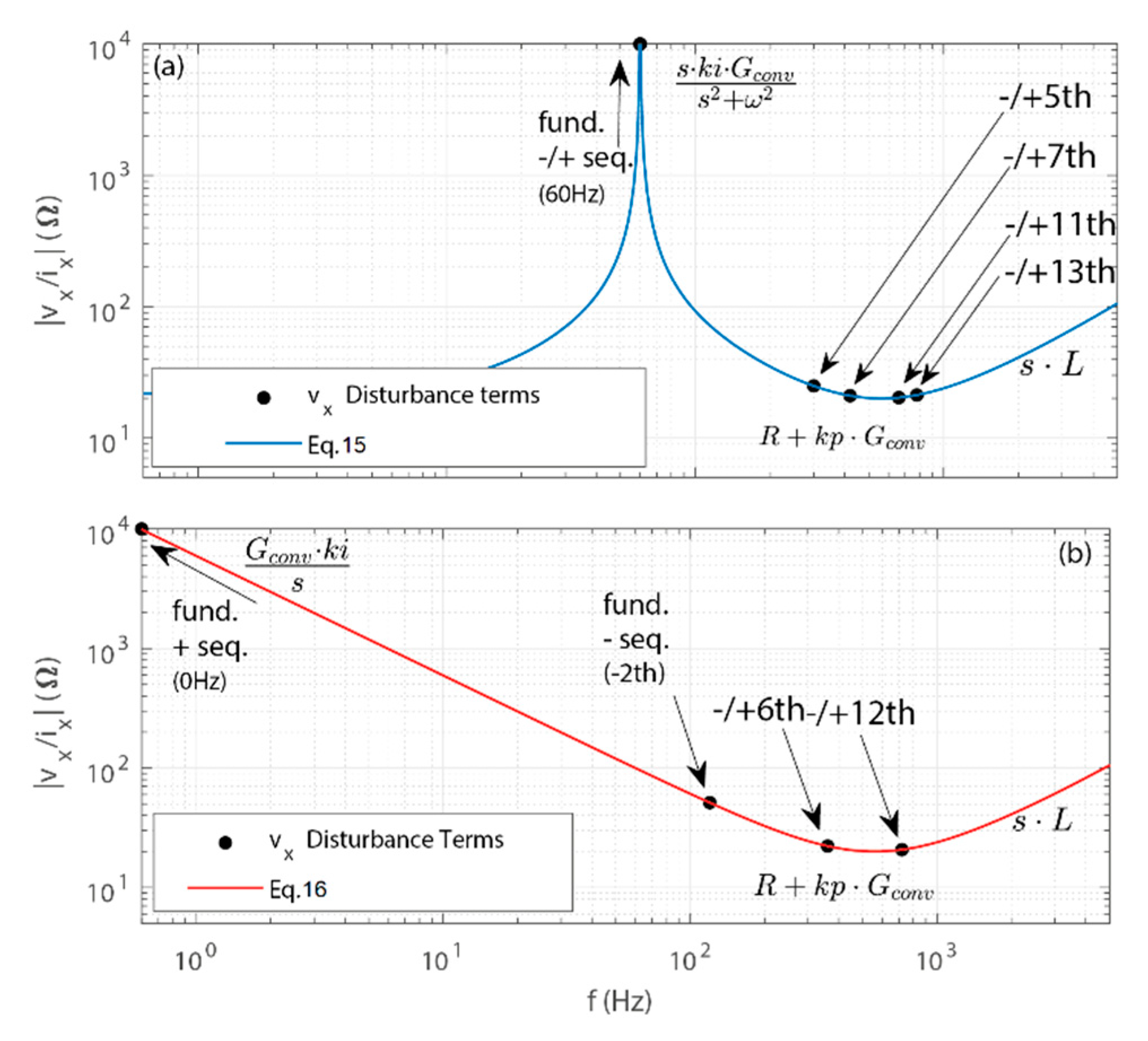
3.1. Basics of Dynamic Stiffness Analysis for Current-Controlled Mode Converter

The DS analysis is a frequency domain tool proposed for steady-state disturbance analysis in mechanical systems, and then expanded to power electronics converters [21]. The DS is used herein as a figure of merit to evaluate the AC current regulators devised in different reference frames over a range of frequency.
The DS has also been applied to power converters analysis [21,22]; and it quantifies the amplitude of the external disturbance needed to produce a unit variation in the controlled-quantity at a specific frequency. In the particular case of grid-connected current-controlled mode converters, the external source is the PCC voltage that disturbs the converter output current. Thus, for grid-following converters, the DS function (14) is the output impedance transfer function in which the unit is ohms [Ω], i.e., D S = ( I / V ) 1 . It is the inverse of the sensitive transfer function (i.e., disturbance rejection −I/V). The vx variable stands for voltage disturbance at PCC, such as fundamental positive- and negative-sequence, and harmonics. The Gconv transfer function is the PWM model plus inverter gain based on the first order Padé approximation [26].
| v x ( s ) i x ( s ) | = | s L + R + C i ( s ) G c o n v |
Figure 4 shows the generalized block diagrams of the current controls of the three reference frames, but for the sake of disturbance analysis the feedforward compensation of the PCC voltages, v x , is disregarded in this section. It is worth underlining that the modulator for the three reference frames is identical and devised in abc-frame, for the sake of a fair comparison.
The AC current regulator Ci(s) is responsible for ensuring high stiffness, robustness, and accurately tracking the current references. The design method of all regulators PI and PR, in every frame, is based on the frequency method considering the same criteria of crossover frequency and phase margin. The comparison is performed under fair conditions for all controllers in the reference frames, considering the same control behavior without any control improvements. Herein, a crossover is assumed frequency of approximately one sixth of switching frequency. The PLL algorithm used is based on well-known decoupled double synchronous reference frame PLL (DDSRF-PLL) [30] with crossover frequency of one third of AC grid line frequency. It is used in abc- and αβ-frame to generate the current references. In dq-frame it is responsible for the signals θ and ω, used respectively for the Park transformation and for canceling the cross coupling. The PLL dynamics can negatively affect the control performance, mainly in weak grids [7,8], but herein it can be neglected due to its slow bandwidth, and considering that no instability was observed during the tests. The current control and PLL parameters are shown in Table 1.
Equations (15) and (16) show the DS functions of a grid-connected VSC considering PR controller applied in stationary frames; and PI controllers applied in synchronous frame. The equivalence between these linear controllers in the stationary and synchronous frame is shown in [9,25,31]. The adopted design method based on crossover frequency and phase margin [26] for both controllers is identical, in which the kp and ki gains are, respectively, the proportional and integral gains, and ωo is the tuned frequency of the resonant term.
| v x ( s ) i x ( s ) | = | s L + R + k p G c o n v + s k i G c o n v s 2 + ω o 2 |
| v x ( s ) i x ( s ) | = | s L + R + k p G c o n v + k i G c o n v s |

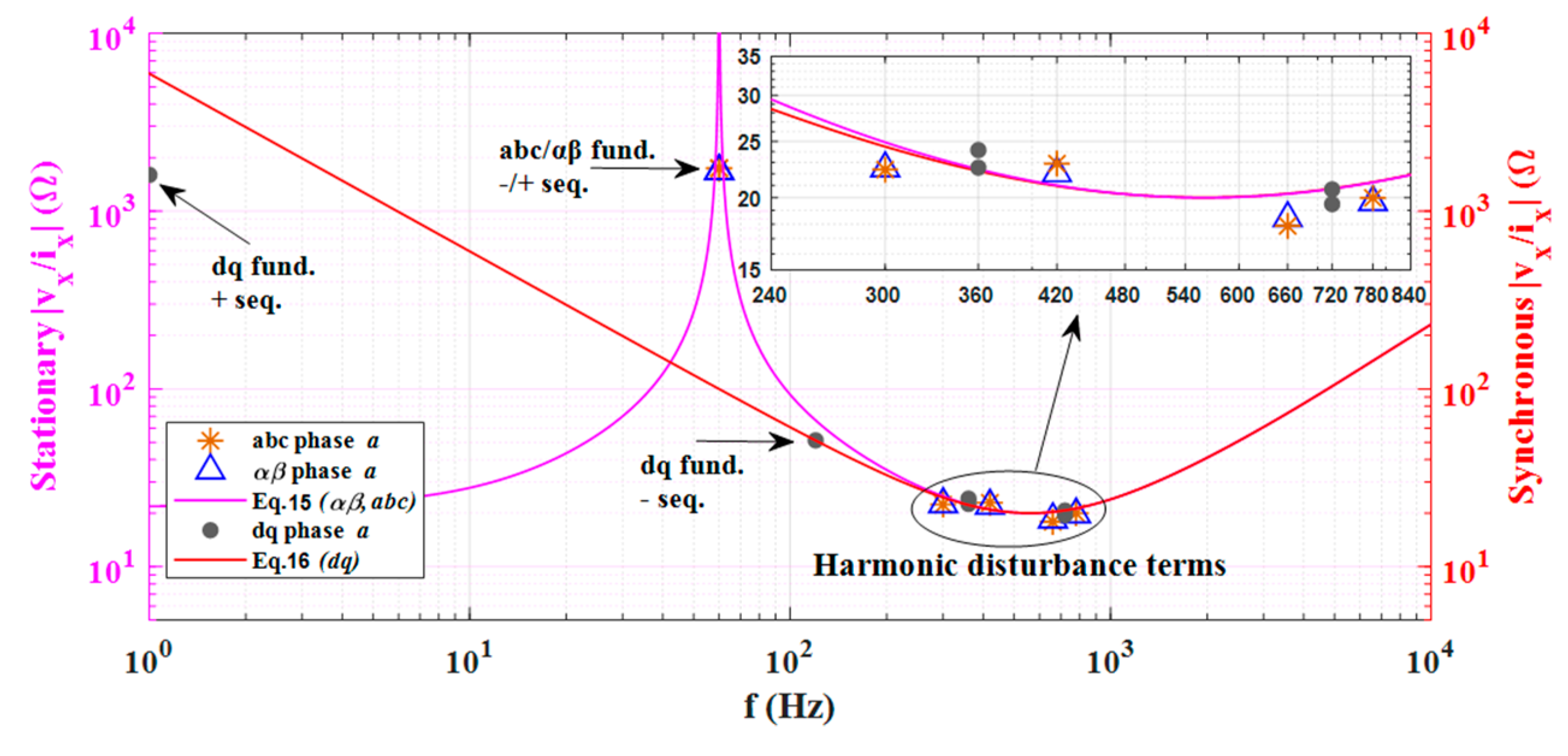
3.2. Case Study of Dynamic Stiffiness Analysis Considering Different Reference Frames

Figure 5a,b show the DS analysis considering (15) and (16) in their corresponding stationary and synchronous reference frame. Figure 5 is based on the system parameters used in the experimental setup shown in Table 2, and detailed in Section 4. This case study considers the PCC voltages, vx, comprising by definition the terms at the fundamental ± sequences, and balanced −5th, +7th, −11th, and +13th harmonics. The resonance in Figure 5a and (15) tuned at the line frequency of 60 Hz improves the reference-tracking ability and disturbance-rejection at 60 Hz for stationary frame approaches. Such PR controller is required because the system tracks sinusoidal time-varying references, and the fundamental positive- and negative-sequence terms of grid voltage disturb the output current at 60 Hz.
Whereas considering the PI regulator in Figure 5b and (16), the lower stiffness value at the fundamental frequency was overcome applying Park’s transformation and converting the controlled-quantities to DC signals, in which the integral action of PI provided very high stiffness value to fundamental positive-sequence component. However, the fundamental negative-sequence oscillated at the −2th frequency, in which the stiffness value was low, as shown in Figure 5b. Further, the Park’s transformation shifts the oscillation of harmonics in dq-frame, for example: the −5th and +7th components were represented in synchronous frame at ±6th, the −11th and +13th components at ±12th, and so on. It is worth underlining that the phase sequence of the harmonics in a three-phase unbalanced grid did not necessarily follow those sequences.
Thus, voltages unbalance triggers oscillation at twice the fundamental frequency (in dq variables), in which dq-frame typically shows lower stiffness values than abc- and αβ-frame. Regarding harmonics, they can oscillate either on one order below or on one order above in the dq-frame whether comparing to stationary-frame. It depends on the sequence-component at each harmonic order presented on the voltages.

4. Experimental Results

The methodology implemented in this paper to compare the control performance in different reference frames is based on experimental results. The electric circuit considered is shown in Figure 1, in which the line voltages are measured and then handled to provide the phase voltages with respect to a virtual point, without considering zero-sequences. The control schemes considered are shown in Figure 4. The DC-link voltage control is out of scope herein, and it is then emulated as an ideal voltage source, without loss of generality. This is accepted considering normalizing the modulators by measured V D C ^ (ratio between modulation signal and measured V D C voltage).
The experimental setup, Figure 6, comprises a 150-MHz float point DSP from Texas Instruments TMS320F28335 and three-phase three-wire VSC from SEMIKRON SEMISTACK with SK30GB128 IGBT modules.
The DC-link was supplied by a DC voltage source and the grid was emulated by a programmable AC power supply 360-ASX from Pacific Power Source. The parameters of the setup are shown in Table 2. The data acquisition used was an oscilloscope TDS2024B from Tektronix.

4.1. Dynamic Stiffness Analysis

The first experimental results shown in Figure 7 and Table 3 consist in analyzing and validating the DS Functions/Equations (15) and (16). This case study considers the SISO current controllers tuned to fundamental frequency, without feedforward compensation of the PCC voltages, to reject the grid voltage disturbance, and current references are set to zero. By programming the 360-ASX power supply, the following components are considered on the grid voltage waveforms: fundamental positive-sequence (1 pu), negative-sequence due to asymmetrical unbalance (0.254 pu), and balanced harmonic components at −5th (0.144 pu), +7th (0.126 pu), −11th (0.141 pu), +13th (0.154 pu). This PCC voltage shows THD value of 24%, considering up to the 51st order.
The output impedance values in Table 3 show that the current control in all reference frames achieved similar behavior with less than 5% of difference among them, except for the fundamental negative-sequence component in dq-frame that showed very high deviation value (about 2000%) in respect to the fundamental positive-sequence component in dq-frame. It is due to lower stiffness at the 2nd harmonic component (120 Hz) than the stationary approaches with PR controllers tuned at 60 Hz. Such results quantify the resilience of each control scheme.
The finite impedance values on the experimental fundamental component for all reference frames refer to the bilinear discretization method applied to the current controllers. The values differ among the system’s phases in the same reference frame because the converter’s legs have inherent mismatching due to prototype’s elements and the windowing limitation on the FFT analysis.
Finally, Figure 6 validates (15) and (16) by accurate experimental results matching with theoretical DS curves. Note that Figure 6 shows both stationary and synchronous reference frames in the same plot, in which pink curve is stationary while red one is dq-frame. It supports the DS analysis and proves that all the controllers are equally sized, because the horizontal and high frequency asymptotes in both curves (15) and (16) are overlapped and intersect each other at the same point, i.e., crossover frequency of 900 Hz as shown in Table 1.

4.2. Asymmetrical Voltage Sag Analysis

Table 4 shows the second experimental result using the Fluke 435 Power Quality Analyzer. This case study consists in evaluating the asymmetrical unbalance under sinusoidal grid voltages caused by sag. The feedforward compensation of the PCC voltages is not considered in this analysis, while the current references are set to zero. The AC power supply is programmed to produce 0.254 pu of negative-sequence voltage on the PCC, by sagging phase a on 76.5%. This quantity is equivalent to produce a unit variation (peak) in the current considering dq-frame, from Table 3 and Figure 7.

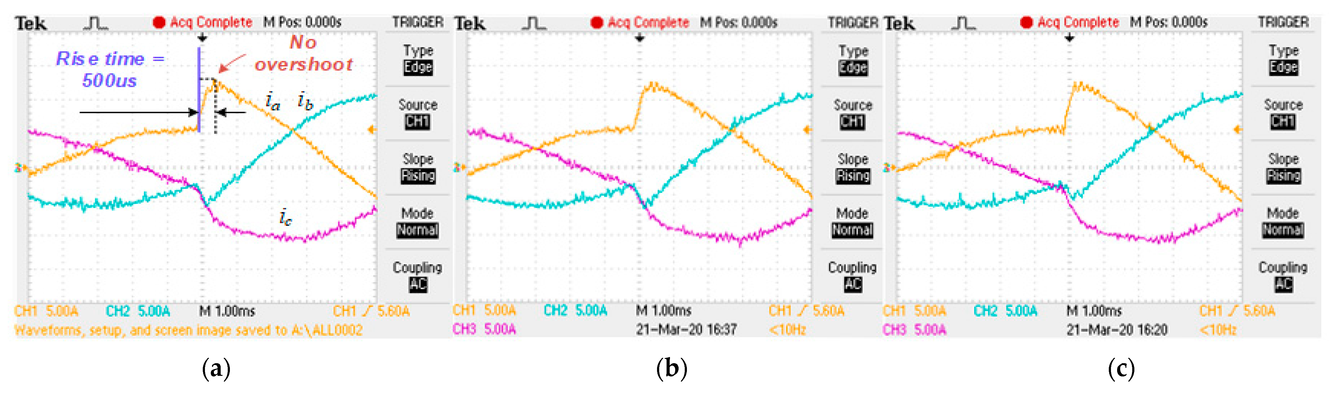
4.3. Transient Analysis

Transient analysis has been performed considering the three reference frames as shown in Figure 8. It is considered a step in the current reference from 50% to 100% of rated power. The transient results show quite similar behavior for all reference frames, with rise time of approximately 500 µs and no overshoot. Such results prove the equivalence between PI controllers in the synchronous frame and the PR controllers in stationary frames corroborating with [9,25,31]. Herein, it proves that all the reference frames are at the same condition in terms of control bandwidth design to perform a fair comparison.

4.4. Steady-State Analysis under Ideal Grid Voltages without Feedforward Compensation of PCC Voltages

This case study is performed upon experimental results of total demand distortion (TDD) of the grid currents (ig in Figure 1), under ideal grid voltages (i.e., sinusoidal and symmetrical) as shown in Table 5—case study 4.4. The TDD of ig is calculated based on the IEEE519-2014 methodology considering up to 51st frequency order. Herein the feedforward compensation of the PCC voltages is disregarded. The power converter exchanges with the grid 80% of rated power. All harmonic components are computed through fast Fourier transform (FFT) processed offline after data acquisition using oscilloscope TDS2024B from Tektronix. The steady-state results, Figure 9, show quite similar behavior for all reference frames.

4.5. Steady-State Analysis under Distorted Grid Voltages without and with Feedforward Compensation of the PCC Voltages

The case studies 4.5a and 4.5b shown in Table 5 evaluate the grid-connected VSC behavior under distorted grid voltages, without and with the feedforward compensation of the PCC voltages, respectively. The PCC voltages are balanced components of fundamental (1 pu), −5th (0.04 pu), and +7th (0.025 pu), resulting in 4.73% of voltage THD per phase. In this scenario, the converter has only current controllers tuned to fundamental frequency, without feedforward compensation, and exchanges with the grid 80% of rated power, with 6.36 A RMS as shown in Figure 8.
For the case study 4.5b, the feedforward compensation of PCC voltages v x is summed to the control voltage references v X * as shown in Figure 4. In the DSP implementation of αβ- and dq-reference frames the v x is applied after the inverse transform to the natural modulation signals. The results are in Table 5—case study 4.5b.
In this analysis, the system shows very close behavior in all reference frames. The feedforward compensation of PCC voltages improves the TDD current value by approximately 30–35%. The feedforward, v x , does not fully eliminate the disturbances because of sampling and transport delays.

4.6. Steady-State Analysis under Distorted Grid Voltages and Multi Resonant Current Control

The case study 4.6 shown in Table 5 and Figure 10 investigates the performance of multi-resonant controllers to enhance reference-tracking ability and disturbance-rejection upon converter output currents. The same voltage configuration of Section 4.4 is used herein. In stationary abc- and αβ-frame, multi-resonant controllers are tuned to the components: fundamental 60 Hz, 5th, and 7th; where kp = 21.6 Ω, ki_60Hz = 12,437 Ω/s, ki_300Hz = 12,437 Ω/s, ki_420Hz = 12,437 Ω/s. While in synchronous dq-frame, due to the frequency shift behavior of Park’s Transformation, only one resonant controller is tuned to 6th component, kp = 21.6 Ω, ki_360Hz = 18,655 Ω/s, (since it considers only balanced −5th and +7th), and one PI controller tracks the fundamental component same as DC quantity. These control schemes match a fair comparison in all reference frames in terms of performances, because the controllers consider the same crossover frequency and phase margin. The resonant controllers are sized based on root loci as in [18], and they are discretized by direct recursive of Tustin operator (bilinear method) [32].
The multi-resonant controllers improved in approximately 76% the TDD values compared to case study 4.5b, increasing the stiffness of the current control at the tuned frequencies. However, comparing the three reference frames, it is concluded that all of them achieved very similar performance in terms of steady-state and transient behavior. The main difference between them was the computational cost involved in their digital implementation, as discussed in Section 4.7.

4.7. Computational Effort Assessment

The last case study results quantify the computational effort considering the control configurations used in this paper: without and with multi-resonant current controllers and implemented by C and assembly (i.e., Digital Control Library—DCL [33]) programming language (ASM). An analytical approach based on the computational effort is shown in Table 6. This analysis is based on the algebraic and trigonometric operations for a fundamental current control in all reference frames proposed and search instantiate the experimental results.
All the measured processing time values shown in Table 7 referred only to the output current control interruption time and exclude other parts of the control algorithm such as PLL and protections. The results showed that the abc frame required 59% and 31% lower computational effort than the dq- and αβ-frame, respectively, considering just one controller, and that required 26% and 15% lower effort than those when considering multi-resonant controllers, as shown in lines 1 and 2 of Table 7. Such a result was achieved due to the absence of reference frame transformation, inherently straightforward implementation for low-cost embedded systems. The results also showed that abc-frame requires 37% lower computational effort when coded in assembly direct form in comparison to C language for fundamental regulator only (see lines 1 and 3 of Table 7 for abc-frame). It is worth underlining that the dq-frame control could be further improved considering another dq-frame rotating -ω with other PI and a resonant controller tuned to 6th. It would attenuate the fundamental negative-sequence, +5th and −7th. However, it would also double the computational time processing of such a control scheme.

5. Conclusions

In this paper, the authors thoroughly investigated implementations of linear AC current regulators for the three-phase three-wire grid-connected converter, considering three different reference frames: natural abc, stationary αβ, and synchronous dq under a distributed generation scheme. The dynamic stiffness, steady-state, transient, and computational efforts were assessed for those three approaches. The dynamic stiffness analysis has shown an accurate figure of merit to evaluate the performance of those AC current controllers under different frequency disturbances, and guarantee that an equal sizing of controllers has been made for the three reference frames compared herein.
A quantitative comparative analysis has been evaluated by experimental results, and acquired data has been validated under the same operational conditions, in order to reflect the proposed mathematical analysis. The transient analysis is similar for the three controllers devised. The steady-state performance of the controller in synchronous-frame (dq), without dual synchronous frame control, was inferior under negative-sequence voltage disturbance when compared to stationary approached (abc) and (αβ). These latter controllers achieved similar experimental performance. Finally, this paper demonstrated that computational requirements for the natural reference frame abc are less constrained because there is a straightforward digital control implementation. Then, the abc-frame controllers should be more explored and used for low digital implementation cost because they achieve similar results in terms of stiffness, transient and steady-state performance requiring lower computational effort. In fact, all the comparison scenarios lead us to very similar results for all the proposed control references, leading us to the conclusion that the main choice factor for the design will be the computational effort of implementing each of the proposed strategies.

Author Contributions

Conceptualization, I.D.L.C., D.I.B. and L.M.F.M.; Methodology, I.D.L.C., D.I.B. and L.M.F.M.; Software, I.D.L.C.; Validation, I.D.L.C., D.I.B. and L.M.F.M.; Formal analysis, I.D.L.C., D.I.B., L.M.J., M.G.S. and L.M.F.M.; Investigation, I.D.L.C., D.I.B. and L.M.F.M.; Resources, I.D.L.C., D.I.B. and L.M.F.M.; Data curation, I.D.L.C., D.I.B. and L.M.F.M.; Writing—original draft preparation, I.D.L.C., D.I.B., L.M.J., M.G.S. and L.M.F.M.; Writing—review and editing, I.D.L.C., D.I.B., L.M.J., M.G.S. and L.M.F.M.; Visualization, I.D.L.C., D.I.B. and L.M.F.M.; Supervision, L.M.F.M. and D.I.B.; Project administration, L.M.F.M. and D.I.B.; Funding acquisition, L.M.F.M. All authors have read and agreed to the published version of the manuscript.

Funding

This study was financed in part by the Coordenação de Aperfeiçoamento de Pessoal de Nível Superior—Brasil (CAPES)—Finance Code 001.

Institutional Review Board Statement

Not applicable.

Informed Consent Statement

Not applicable.

Acknowledgments

The authors acknowledge Victor Flores Mendes from UFMG for providing the research facilities of Laboratory of Energy Conversion and Control (LCCE-UFMG) and the test bench to obtain the experimental results.

Conflicts of Interest

The authors declare no conflict of interest.

References

  1. IEEE Standards Coordinating Committee. IEEE standard for interconnection and interoperability of distributed energy resources with associated electric power systems interfaces. In IEEE Std 1547-2018; Revision of IEEE Std 1547-2003; IEEE: New York, NY, USA, 2018; pp. 1–138. [Google Scholar]
  2. Teodorescu, R.; Liserre, M.; Rodriguez, P. Grid Converters for Photovoltaic and Wind Power Systems; John Wiley & Sons: Oxford, UK, 2011. [Google Scholar]
  3. Callegari, J.; Silva, M.; de Barros, R.; Brito, E.; Cupertino, A.; Pereira, H. Lifetime evaluation of three-phase multifunctional PV inverters with reactive power compensation. Electr. Power Syst. Res. 2019, 175, 105873. [Google Scholar] [CrossRef]
  4. Amorim, T.S.; Carletti, D.; Encarnação, L.F. Comparison of inverter controllers with synthetic inertia and harmonic compensation features. Electr. Power Syst. Res. 2021, 197, 107344. [Google Scholar] [CrossRef]
  5. Silva, R.M.; Cupertino, A.F.; Rezende, G.M.; Sousa, C.V.; Mendes, V.F. Power control strategies for grid connected converters applied to full-scale wind energy conversion systems during LVRT operation. Electr. Power Syst. Res. 2020, 184, 106279. [Google Scholar] [CrossRef]
  6. Zhu, D.; Zhou, S.; Zou, X.; Kang, Y. Improved design of PLL controller for LCL-type grid-connected converter in weak grid. IEEE Trans. Power Electron. 2020, 35, 4715–4727. [Google Scholar] [CrossRef]
  7. Sukegawa, T.; Ikimi, T.; Matsutake, M.; Kamiyama, K.; Takahashi, J. A multiple PW GTO line-side converter for unity power factor and reduced harmonics. IEEE Trans. Ind. Appl. 1992, 28, 1302–1308. [Google Scholar] [CrossRef]
  8. Zhou, S.; Zou, X.; Zhu, D.; Tong, L.; Zhao, Y.; Kang, Y.; Yuan, X. An improved design of current controller for LCL-type grid-connected converter to reduce negative effect of PLL in weak grid. IEEE J. Emerg. Sel. Top. Power Electron. 2018, 6, 648–663. [Google Scholar] [CrossRef]
  9. Mirhosseini, M.; Pou, J.; Karanayil, B.; Agelidis, V.G. Resonant versus conventional controllers in grid-connected photovoltaic power plants under unbalanced grid voltages. IEEE Trans. Sustain. Energy 2016, 7, 1124–1132. [Google Scholar] [CrossRef]
  10. Ochoa-Giménez, M.; Roldán-Peréz, J.; García-Cerrada, A.; Zamora-Macho, J.L. Efficient multiple-reference-frame controller for harmonic suppression in custom power devices. Int. J. Electr. Power Energy Syst. 2015, 69, 344–353. [Google Scholar] [CrossRef]
  11. Bahrani, B.; Karimi, A.; Rey, B.; Rufer, A. Decoupled -current control of grid-tied voltage source converters using nonparametric models. IEEE Trans. Ind. Electron. 2013, 60, 1356–1366. [Google Scholar] [CrossRef]
  12. Zargari, N.R.; Joos, G. Performance investigation of a current-controlled voltage-regulated PWM rectifier in rotating and stationary frames. IEEE Trans. Ind. Electron. 1995, 42, 396–401. [Google Scholar] [CrossRef]
  13. Montero, M.I.M.; Cadaval, E.R.; Gonzalez, F.B. Comparison of control strategies for shunt active power filters in three-phase four-wire systems. IEEE Trans. Power Electron. 2007, 22, 229–236. [Google Scholar] [CrossRef]
  14. Wu, R.; Dewan, S.B.; Slemon, G.R. Analysis of an AC-to-DC voltage source converter using PWM with phase and amplitude control. IEEE Trans. Ind. Appl. 1991, 27, 355–364. [Google Scholar] [CrossRef]
  15. Hayashi, P.H.I.; Matakas, L. Decoupled stationary ABC frame current control of three-phase four-leg four-wire converters. In Proceedings of the Brazilian Power Electronics Conference (COBEP), Juiz de Fora, Brazil, 19–22 November 2017; pp. 1–6. [Google Scholar]
  16. Holmes, D.G.; Lipo, T.A.; McGrath, B.P.; Kong, W.Y. Optimized design of stationary frame three phase AC current regulators. IEEE Trans. Power Electron. 2009, 24, 2417–2426. [Google Scholar] [CrossRef]
  17. Buso, S.; Malesani, L.; Mattavelli, P. Comparison of current control techniques for active filter applications. IEEE Trans. Ind. Electron. 1998, 45, 722–729. [Google Scholar] [CrossRef]
  18. Timbus, A.; Liserre, M.; Teodorescu, R.; Rodriguez, P.; Blaabjerg, F. Evaluation of current controllers for distributed power generation systems. IEEE Trans. Power Electron. 2009, 24, 654–664. [Google Scholar] [CrossRef]
  19. Kong, W.Y.; Holmes, D.G.; McGrath, B.P. Improved stationary frame AC current regulation using feedforward compensation of the load EMF. In Proceedings of the Twenty-Fourth Annual IEEE Applied Power Electronics Conference and Exposition, Washington, DC, USA, 15–19 February 2009; pp. 145–151. [Google Scholar]
  20. Chaves, H.; Heldwein, M.L. Grid-tied three-phase inverter current control considering low voltage ride through capability: A comparison between stationary and synchronous reference frames. In Proceedings of the IEEE 11th International Symposium on Power Electronics for Distributed Generation Systems (PEDG), Dubrovnik, Croatia, 28 September–1 October 2020; pp. 57–62. [Google Scholar]
  21. Lorenz, R.D.; Lipo, T.A.; Novotny, D.W. Motion control with induction motors. Proc. IEEE 1994, 82, 1215–1240. [Google Scholar] [CrossRef]
  22. Ryan, M.; Brumsickle, W.; Lorenz, R. Control topology options for single-phase UPS inverters. IEEE Trans. Ind. Appl. 1997, 33, 493–501. [Google Scholar] [CrossRef] [Green Version]
  23. Alonso, A.M.D.S.; Brandao, D.I.; Tedeschi, E.; Marafão, F.P. Distributed selective harmonic mitigation and decoupled unbalance compensation by coordinated inverters in three-phase four-wire low-voltage networks. Electr. Power Syst. Res. 2020, 186, 106407. [Google Scholar] [CrossRef]
  24. Souza, R.R.; Moreira, A.B.; Barros, T.A.; Ruppert, E. A proposal for a wind system equipped with a doubly fed induction generator using the Conservative Power Theory for active filtering of harmonics currents. Electr. Power Syst. Res. 2018, 164, 167–177. [Google Scholar] [CrossRef]
  25. Zmood, D.; Holmes, D.; Bode, G. Frequency-domain analysis of three-phase linear current regulators. IEEE Trans. Ind. Appl. 2001, 37, 601–610. [Google Scholar] [CrossRef]
  26. Buso, S.; Mattavelli, P. Digital Control in Power Electronics, 1st ed.; Morgan & Claypool: San Rafael, CA, USA, 2006. [Google Scholar]
  27. Song, H.-S.; Nam, K. Dual current control scheme for PWM converter. IEEE Trans. Ind. Electron. 1999, 46, 953–959. [Google Scholar] [CrossRef]
  28. Moreno, V.M.; Liserre, M.; Pigazo, A.; Dell’Aquila, A. A comparative analysis of real-time algorithms for power signal decomposition in multiple synchronous reference frames. IEEE Trans. Power Electron. 2007, 22, 1280–1289. [Google Scholar] [CrossRef]
  29. Marin, L.; Tarraso, A.; Candela, I.; Rye, R.; Rodriguez, P. Influence of the ICFF decoupling technique on the stability of the current control loop of a grid-tied VSC. In Proceedings of the IEEE Energy Conversion Congress and Exposition (ECCE), Baltimore, MD, USA, 29 September–3 October 2019; pp. 2622–2628. [Google Scholar]
  30. Rodriguez, P.; Pou, J.; Bergas, J.; Candela, J.I.; Burgos, R.P.; Boroyevich, D. Decoupled double synchronous reference frame PLL for power converters control. IEEE Trans. Power Electron. 2007, 22, 584–592. [Google Scholar] [CrossRef]
  31. Zmood, D.; Holmes, D. Stationary frame current regulation of PWM inverters with zero steady state error. IEEE Trans. Power Electron. 2003, 18, 814–822. [Google Scholar] [CrossRef]
  32. Amini, B.; Roshanfekr, R.; Hajipoor, A.; Mousavi, S.Y.M. Interface converter control of distributed generation in microgrids using fractional proportional—Resonant controller. Electr. Power Syst. Res. 2021, 194, 107097. [Google Scholar] [CrossRef]
  33. Texas Instruments, Incorporated. C2000™ Digital Controller Library; SPRUI31; Texas Instruments: Dallas, TX, USA, 2015. [Google Scholar]
Figure 1. Grid-connected two-level three-phase three-wire voltage source converter.
Energies 14 08348 g001
Figure 2. Cascade control scheme of the grid-connected voltage source converter.
Energies 14 08348 g002
Figure 3. Equivalent circuit of three-phase three-wire grid-connected VSCs, considering Zg = 0 Ω and then eabc = vabc. (a) Power system modeling, and (b) power convert modeling.
Energies 14 08348 g003
Figure 4. Current control scheme for three-phase three-wire grid-tied VSC. (a) abc-frame, (b) αβ-frame, and (c) dq-frame.
Energies 14 08348 g004
Figure 5. Dynamic stiffness analysis: (a) PR controller in abc and αβ frame, and (b) PI controller in dq frame.
Energies 14 08348 g005
Figure 6. Experimental setup. (a) Building blocks. (b) External view under operation.
Energies 14 08348 g006
Figure 7. DS analysis experimental results of PI current controller in dq-frame; and fundamental PR current controller in abc- and αβ-frame.
Energies 14 08348 g007
Figure 8. Transient analysis of current control, without feedforward compensation. (a) abc–PR, (b) αβ–PR, and (c) dq–PI.
Energies 14 08348 g008
Figure 9. Steady-state analysis of current loop under distorted grid voltages, without feedforward compensation. (a) abc–PR, (b) αβ–PR, and (c) dq–PI.
Energies 14 08348 g009
Figure 10. Steady-state analysis of multi-resonant control under distorted voltage. (a) abc–PR fund. +5th +7th, (b) αβ–PR fund. +5th +7th and (c) dq–PI + 6th resonant.
Energies 14 08348 g010
Table 1. Parameters of PLL and current control.
Controllerkp [Ω]ki [Ω/s]Crossover Freq.Phase Margin
PI (dq)21.637,311900 Hz60°
PR60Hz (abc/αβ)21.637,311 900 Hz60°
PI (DDSRF-PLL)0.74249.523.2 Hz65°
Table 2. Parameters of experimental setup.
ParameterValue
Grid voltage (PCC RMS phase voltage vxn)127 V
Grid frequency (fgrid)60 Hz
Grid inductance (Lg)1.73 mH
Converter rated current (RMS)7.87 A
Converter rated power3 kW
DC link voltage (VDC)450 V
Converter switch frequency (fsw)6 kHz
DSP control sampling frequency (fsampling)12 kHz
Converter filter inductance (L)
Converter filter resistance (R)
Converter filter capacitance (C)
4 mH
0.157 Ω
1 µF
Converter DC capacitance (CDC)3.06 mF
Proportional gain current control kp21.63 Ω
Integral gain current control ki37311.47 Ω/s
Table 3. Comparison between experimental and theoretical dynamic stiffness values (Ω).
Experimental Theoretical
ComponentabcαβdqPI dq ModelPR abc/αβ Model
abcabcabc
+Fund. Seq.174311611192168112271147160011931393
–Fund. Seq.17431161119216811227114751.3851.0250.9051.28
–5th22.3523.7724.8422.4624.0724.8222.5323.7824.4424.4824.91
+7th22.8822.7023.0622.0322.1022.9024.1623.2223.8820.9520.99
–11th17.8720.2621.0418.4320.7021.4519.4521.8622.2520.3220.30
+13th19.9718.1019.2419.6418.0719.5220.6719.2820.4621.2721.24
Table 4. Output current disturbance due asymmetrical voltage sag—rms values.
Experimental Test Considering Voltage Sag
Ref.va[V]vb[V]vc[V]ia[A]ib[A]ic[A]
abc30.1 127.6127.40.1040.0610.046
αβ30.0 127.6127.40.1020.0590.050
dq30.5128.7125.20.7360.7170.677
Table 5. Experimental results from case studies—total demand distortion TDD (%).
Case Study 4.4Case Study 4.5aCase Study 4.5bCase Study 4.6
Legabcαβdqabcαβdqabcαβdqabcαβdq
a1.1501.3801.1374.6694.4434.4943.0942.9422.7271.1151.0541.226
b1.3781.5501.3124.3844.6954.4772.9832.8062.9361.1101.1671.043
c1.4301.4191.3544.5194.5224.2763.2792.9293.0211.3071.2261.047
Table 6. Computational effort based on the number of algebraic and trigonometric operations.
SumsSubtractionsProductsTrigonometric
abc5782
αβ511172
dq1561612
Table 7. Measured computational effort—% of sample period.
abcαβdq
C-Fund.1.69%2.45%4.13%
C-Fund plus Multi control4.12%4.88%5.60%
Asm direct-Fund.1.06%1.93%2.66%
Asm direct-Fund plus Multi2.53%3.30%3.62%
Publisher’s Note: MDPI stays neutral with regard to jurisdictional claims in published maps and institutional affiliations.

