
Investigating Hydrogen-Based Non-Conventional Storage for PV Power in Eco-Energetic Optimization of a Multi-Energy System


Abstract
:1. Introduction
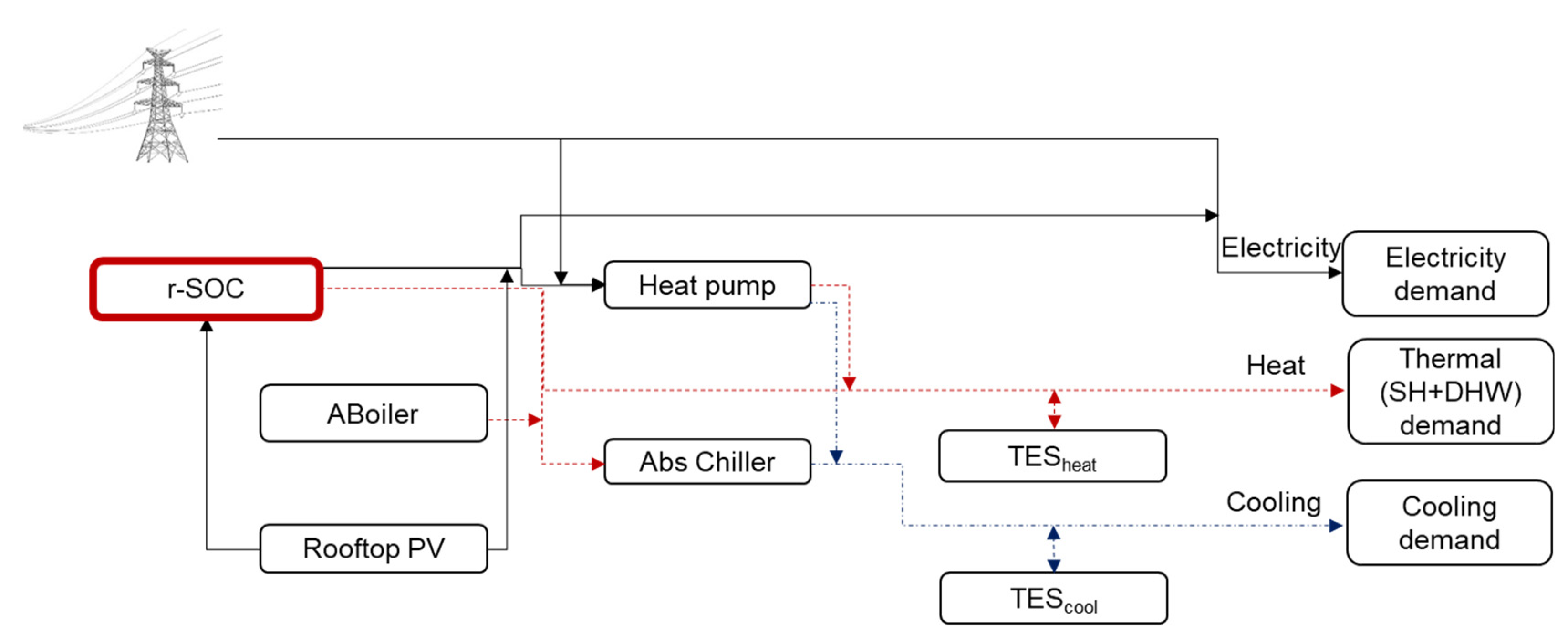
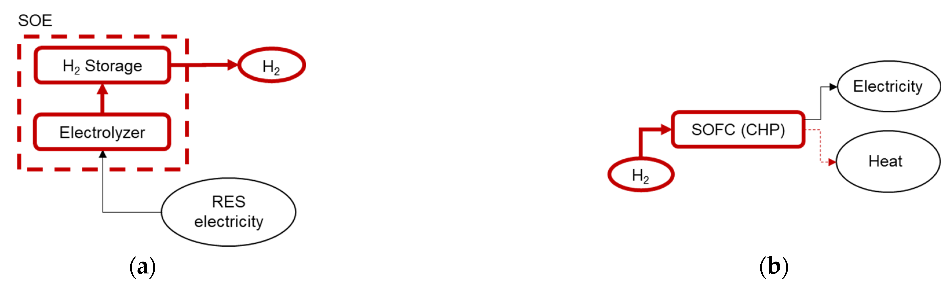
2. Description of the Multi-Energy System
3. Optimal Design Model
3.1. Decision Variables
3.2. Objective Functions
3.3. Problem Constraints
3.3.1. Design Constraints
3.3.2. Operation Constraints and Modeling of Energy Technologies in the MES
3.3.3. Energy Balance Constraints
3.4. Multi-Objective Optimization and Solution Methodology
4. Case Study
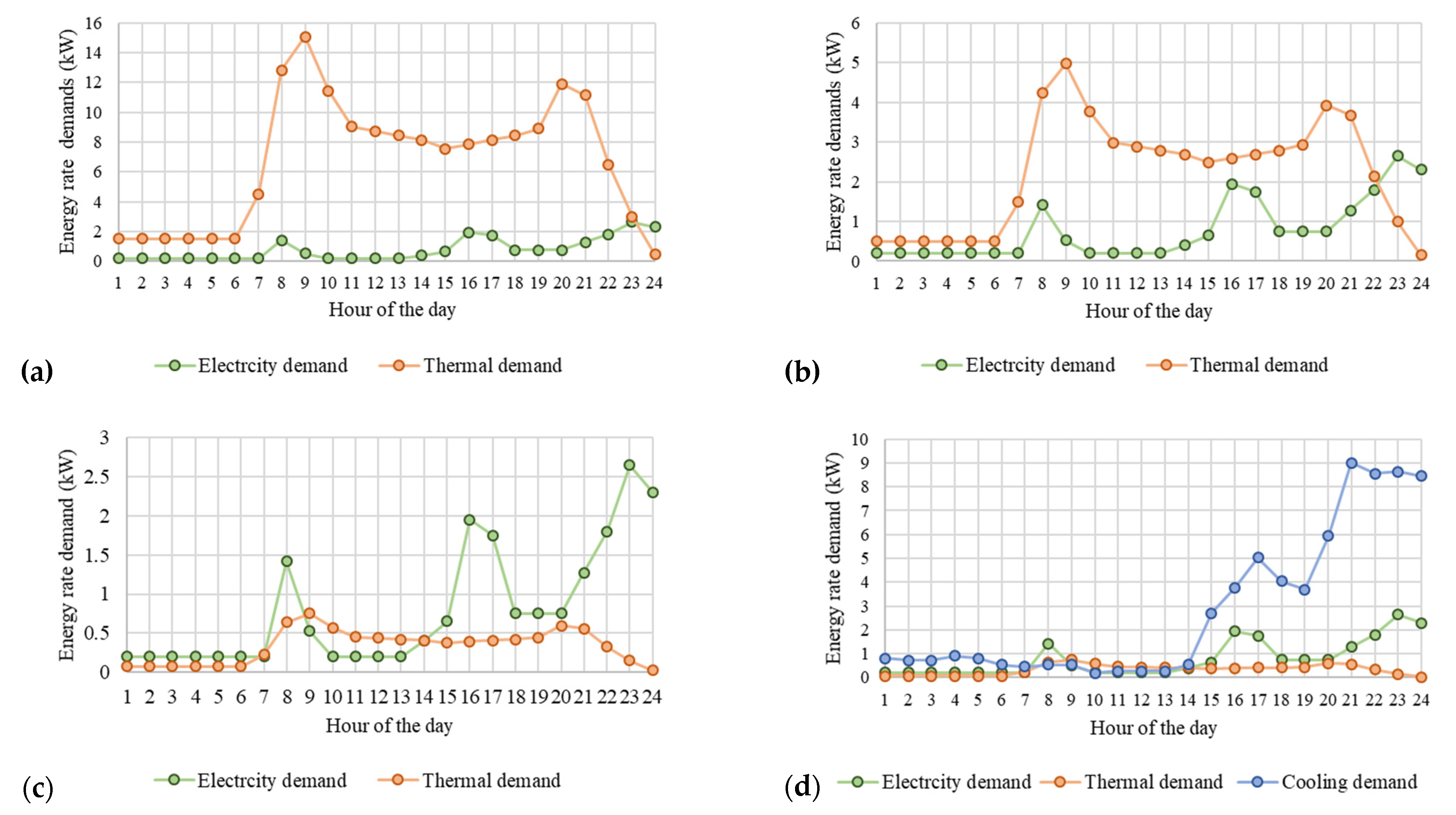
4.1. Input Data
- -
- Hourly load profiles for electricity, space heating and domestic hot water and cooling for the residential user. In order to be able to simulate 15 consecutive days, it is assumed that the days of the same season have the same load profiles as the representative day of the season;
- -
- The irradiance profile on an hourly basis on a 35° tilted surface for the city of Turin [24]. In order to be able to simulate the 15 consecutive days, it is assumed that the days of the same season have the same irradiance profiles as the representative day of the season;
- -
- The prices of energy carriers (electricity and gas), referring to the national energy market. In detail, the unit price of natural gas is assumed as 0.462 €/Nm3, whereas the time-of-day electricity price is assumed to vary between 0.123 and 0.152 €/kWh. The reference electrical efficiency of the Italian thermoelectric park is set to 0.488 [25].
- -
- The technical–economic characteristics of the technologies that can be implemented as indicated in Table 1. The maximum available area for installation of the rooftop PV arrays is assumed to be 190 m2. The efficiency of the hydrogen storage is assumed to be 1. The techno–economic information of the r-SOC are based on data collected from market investigation of fuel cell producers.
4.2. Optimization Results
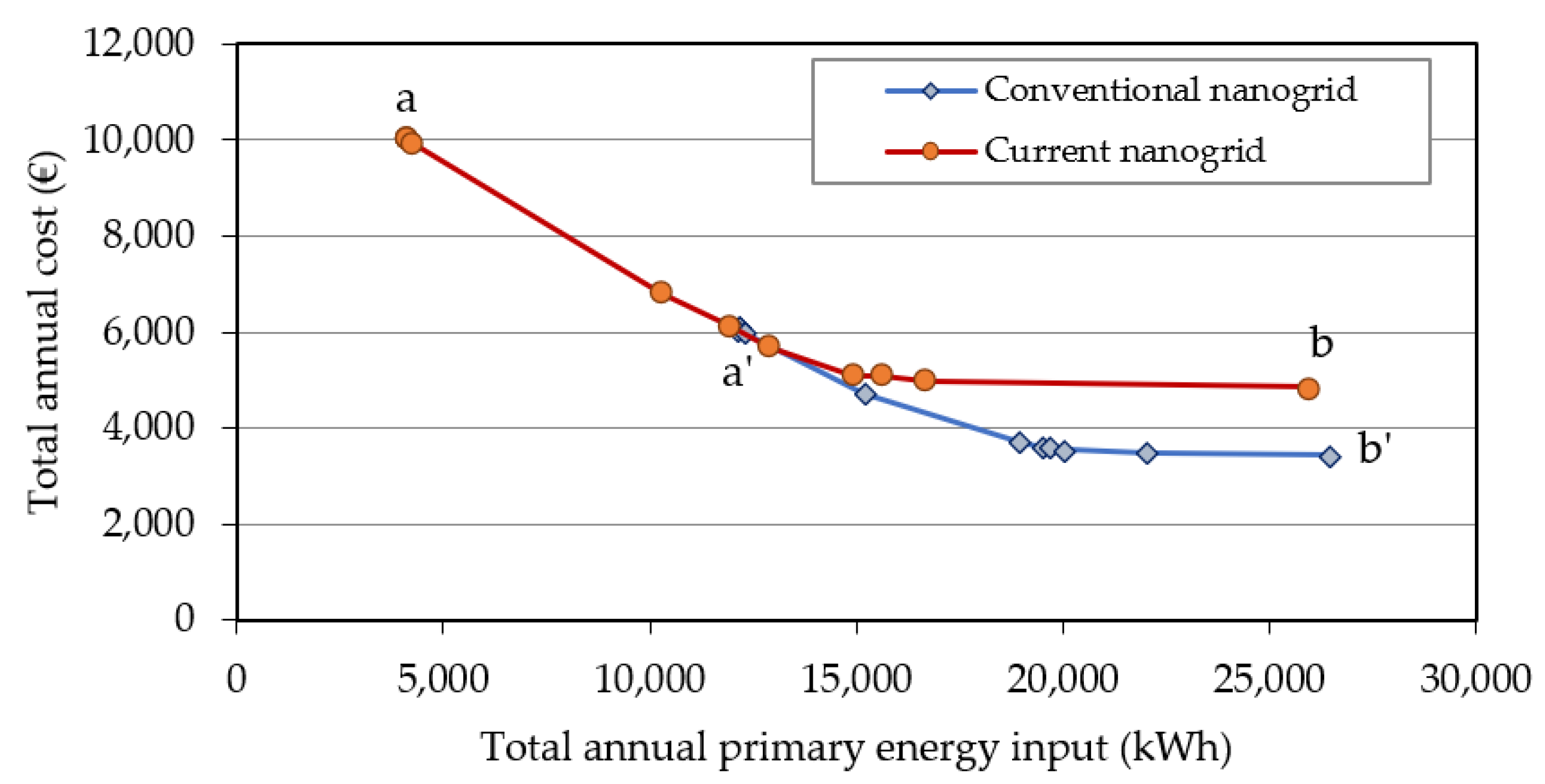
4.2.1. Pareto Frontier
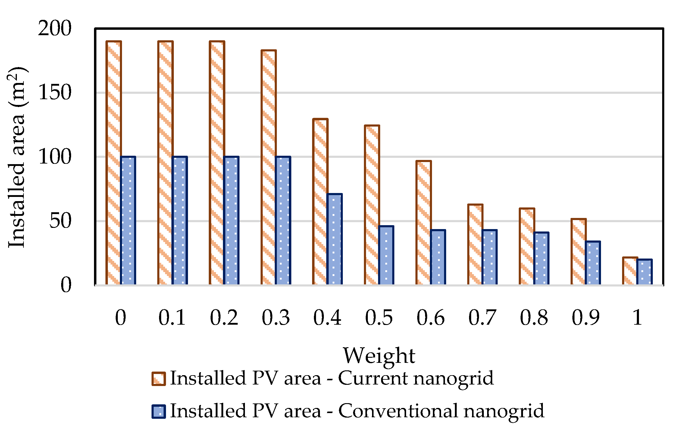
4.2.2. Optimal Design Solutions
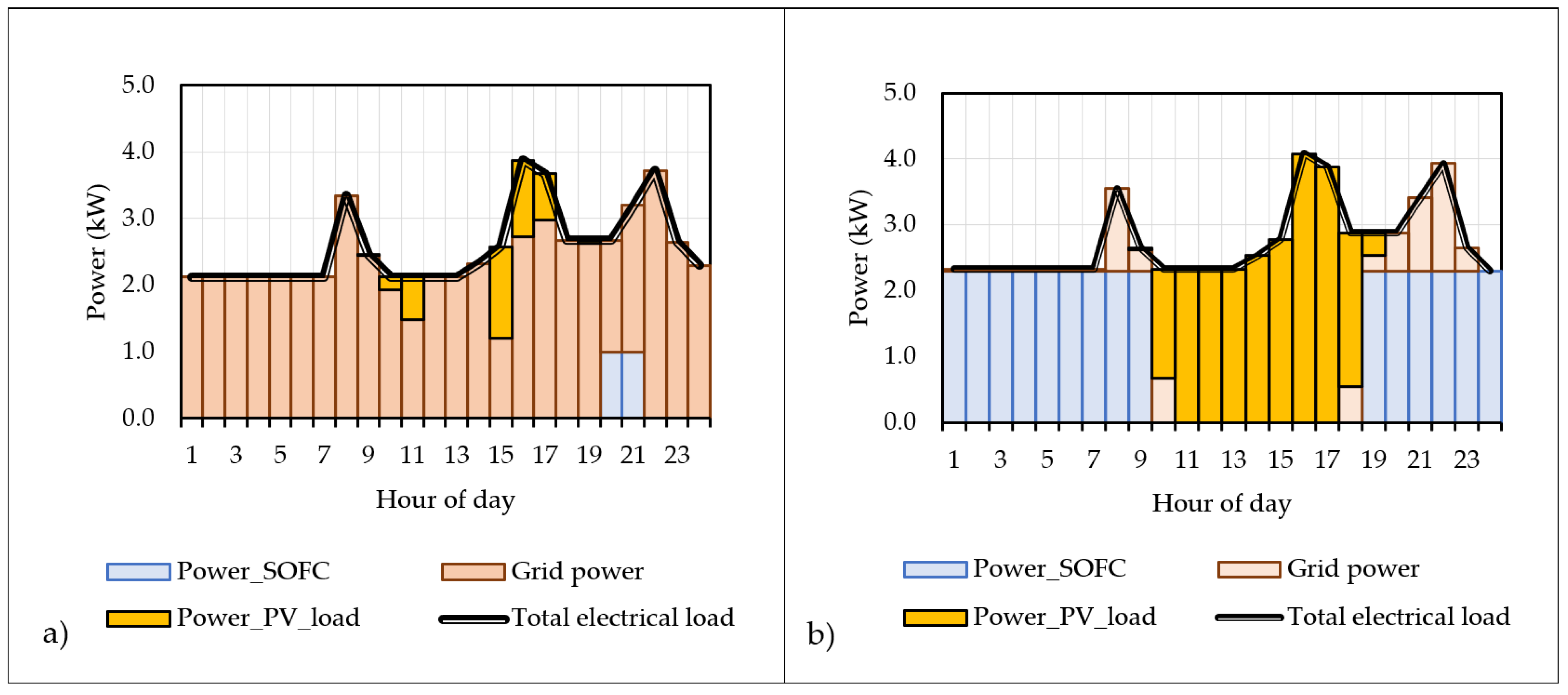
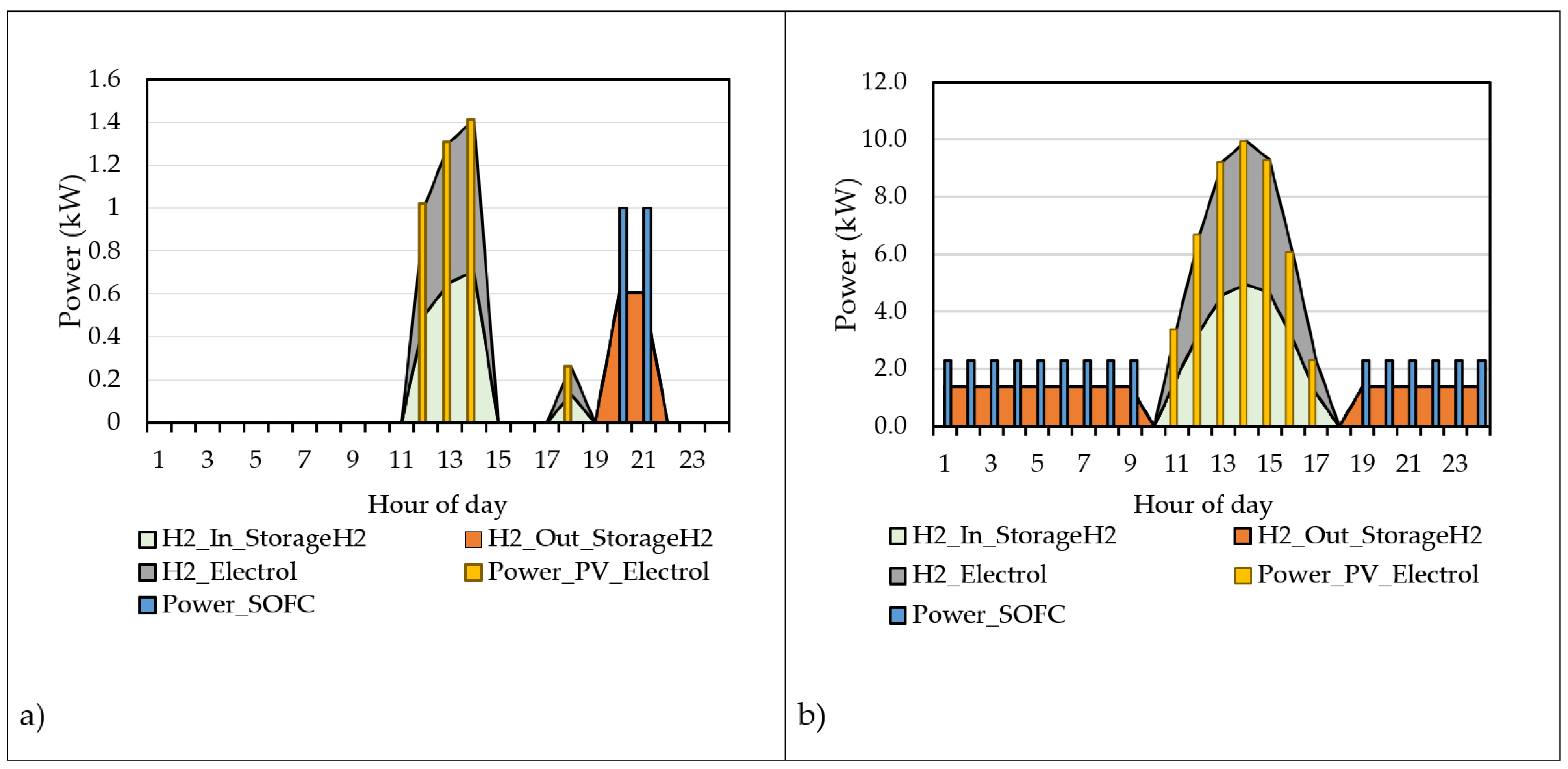
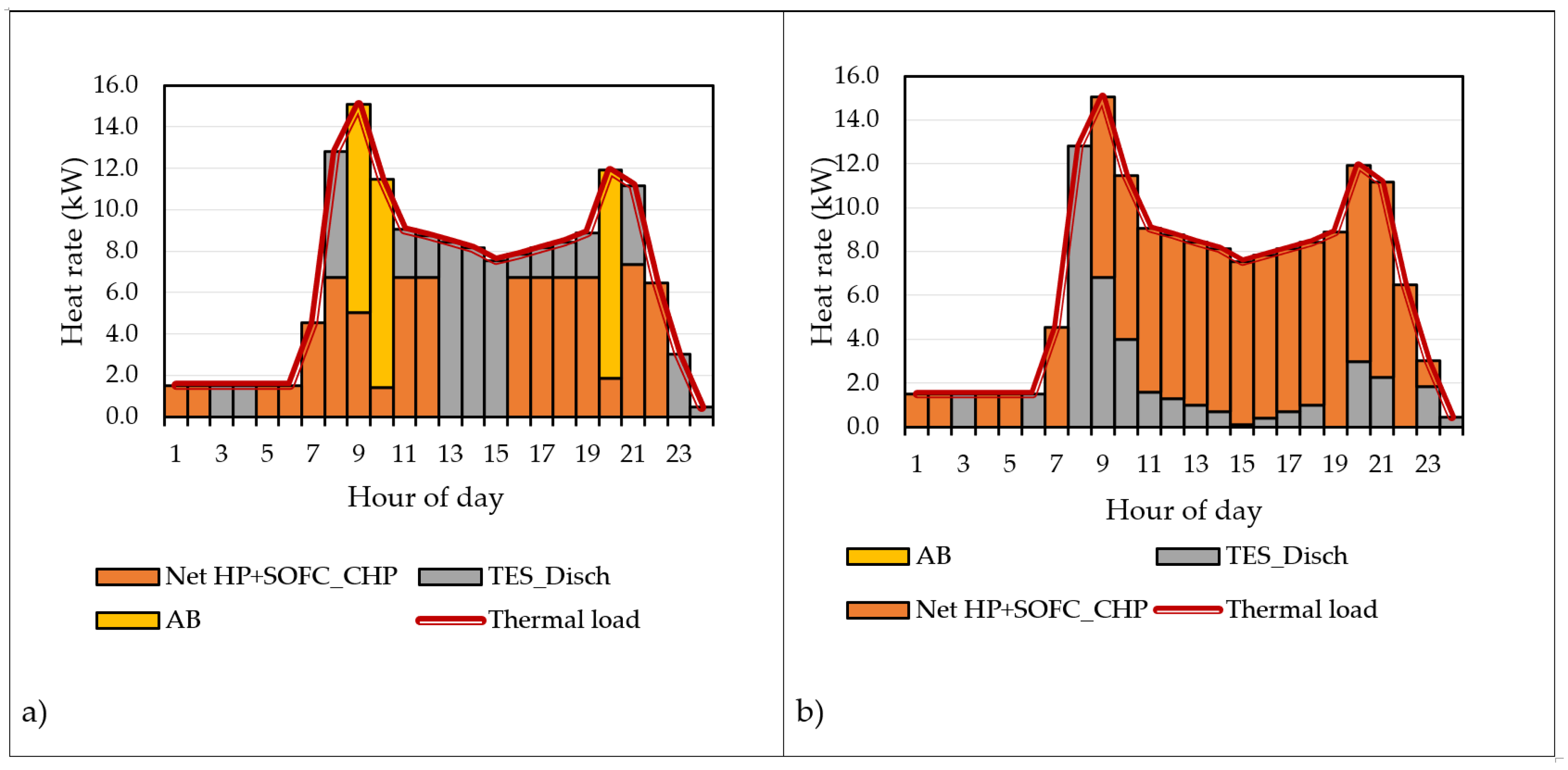
4.2.3. Operation Strategies of the Optimized MES Configurations under the Extreme Points on the Pareto Frontier
5. Conclusions
Author Contributions
Funding
Conflicts of Interest
Nomenclature
| Decision variables | |
| APV | installed area of rooftop PV (m2) |
| C | cost (€) |
| Ed,hr | power (kW) |
| ej,d,hr | technology’s generation level (kW) |
| Fobj | objective function |
| Gd,hr | volumetric flow rate of natural gas (Nm3/h) |
| H2d,hr | volumetric flow rate of hydrogen (m3/h) |
| Hd,hr | heat rate (kW) |
| PE | primary energy input (kWh) |
| S | designed size (kW)–(kWh) |
| x | binary decision variable |
| Parameters | |
| Amax | available area for rooftop PV (m2) |
| c | constant in Equation (30) (kWh/€) |
| Cc | specific capital cost (€/kW)–(€/kWh)–(€/m2) |
| COP | coefficient of performance |
| CRF | capital recovery factor |
| Dt | time interval length (h) |
| Emax | capacity of the technology (kW) |
| Emin | mimimum part load of the technology (kW) |
| Id,hr | total solar irradiance (kW/m2) |
| LHVgas | lower heat value of natural gas (kWh/Nm3) |
| LHVH2 | lower heat value of hydrogen (kWh/m3) |
| N | lifetime (years) |
| OM | specific O&M cost (€/kWh) |
| Pe,hr | electricity price (€/kWh) |
| Pgas | natural gas price (€/Nm3) |
| r | interest rate |
| Smax | maximum size available in the market (kW) |
| Smin | minimum size available in the market (kW) |
| η | efficiency |
| ηe,ref | reference electrical efficiency of the power grid |
| φTES | storage loss fraction |
| ω | weight in Equation (30) |
| Superscript/Subscripts | |
| AB | auxiliary boiler |
| AChil | absorption chiller |
| Ch | charging |
| d | day |
| dem | demand |
| Disch | discharging |
| Elect | electrolyzer |
| fuel | fuel |
| grid power | grid power |
| H2 | hydrogen |
| HM | heating mode |
| hr | hour |
| INV | investment |
| j | index of energy technology |
| max | maximum |
| min | minimum |
| O&M | operation and maintenance |
| PG | power grid |
| PV | photovoltaic |
| req | required |
| SC | space cooling |
| SOE | SOE mode |
| SOFC | SOFC mode |
| Sto | stored |
| TES | thermal energy storage |
| Th | thermal |
| TOT | total |
| Acronyms | |
| CHP | micro combined heat and power |
| MES | multi energy system |
| MILP | mixed-integer linear programming |
| O&M | operation and maintenance |
| PV | photovoltaic |
| r-SOC | reversible solid oxide fuel cell |
| SOE | solid oxide electrolyzer |
| SOFC | solid oxide fuel cell |
References
- Mladenov, V.; Chobanov, V.; Georgiev, A. Impact of Renewable Energy Sources on Power System Flexibility Requirements. Energies 2021, 14, 2813. [Google Scholar] [CrossRef]
- Chicco, G.; Di Somma, M.; Graditi, G. Overview of distributed energy resources in the context of local integrated energy systems. In Distributed Energy Resources in Local Integrated Energy System; Di Somma, M., Graditi, G., Eds.; Elsevier: Amsterdam, The Netherlands, 2021; pp. 1–29. [Google Scholar]
- Vahid-Ghavidel, M.; Javadi, M.S.; Gough, M.; Santos, S.F.; Shafie-Khah, M.; Catalão, J.P. Demand response programs in multi-energy systems: A review. Energies 2020, 13, 4332. [Google Scholar] [CrossRef]
- Roberto, R.; De Iulio, R.; Di Somma, M.; Graditi, G.; Guidi, G. A multi-objective optimization analysis to assess the potential economic and environmental benefits of distributed storage in district heating networks: A case study. Int. J. Sustain. Energy Plan Manag. 2019, 20, 5–20. [Google Scholar] [CrossRef]
- Eveloy, V.; Romeo, L.M.; Parra, D.; Qadrdan, M. Editorial: Advances in Power-to-X: Processes, Systems, and Deployment; Frontiers Media SA: Lausanne, Switzerland, 2021. [Google Scholar] [CrossRef]
- Cigolotti, V.; Genovese, M.; Fragiacomo, P. Comprehensive review on fuel cell technology for stationary applications as sustainable and efficient poly-generation energy systems. Energies 2021, 14, 4963. [Google Scholar] [CrossRef]
- Sanders, D.; Hart, A.; Ravishankar, M.; Brunert, J.; Strbac, G.; Aunedi, M. An Analysis of Electricity System Flexibility for Great Britain; Carbon Trust/Imperial College: London, UK, 2016. [Google Scholar]
- Strbac, G.; Pudjianto, D.; Sansom, R.; Djapic, P.; Ameli, H.; Shah, N.; Brandon, N.; Hawkes, A.; Qadrdan, M. Analysis of Alternative UK Heat Decerbonisation Pathways; Imperial College London: London, UK, 2018. [Google Scholar]
- Fu, P.; Pudjianto, D.; Zhang, X.; Strbac, G. Integration of Hydrogen into Multi-Energy Systems Optimisation. Energies 2020, 13, 1606. [Google Scholar] [CrossRef] [Green Version]
- Mancarella, P. MES (multi-energy systems): An overview of concepts and evaluation models. Energy 2014, 65, 1–17. [Google Scholar] [CrossRef]
- Bottecchia, L.; Lubello, P.; Zambelli, P.; Carcasci, C.; Kranzl, L. The Potential of Simulating Energy Systems: The Multi Energy Systems Simulator Model. Energies 2021, 14, 5724. [Google Scholar] [CrossRef]
- IRENA. International Renewable Energy Agency Global Renewables Outlook: Energy Transformation 2050; IRENA: Abu Dhabi, United Arab Emirates, 2020. [Google Scholar]
- Bailera, M.; Peña, B.; Lisbona, P.; Romeo, L.M. Decision-making methodology for managing photovoltaic surplus electricity through Power to Gas: Combined heat and power in urban buildings. Appl. Energy 2018, 228, 1032–1045. [Google Scholar] [CrossRef] [Green Version]
- Thomas, J.M.; Edwards, P.P.; Dobson, P.J.; Owen, G.P. Decarbonising energy: The developing international activity in hydrogen technologies and fuel cells. J. Energy Chem. 2020, 51, 405–415. [Google Scholar] [CrossRef] [PubMed]
- Gabrielli, P.; Gazzani, M.; Mazzotti, M. Electrochemical conversion technologies for optimal design of decentralized multi-energy systems: Modeling framework and technology assessment. Appl. Energy 2018, 221, 557–575. [Google Scholar] [CrossRef]
- Davis, S.J.; Lewis, N.S.; Shaner, M.; Aggarwal, S.; Arent, D.; Azevedo, I.L.; Benson, S.M.; Bradley, T.; Brouwer, J.; Chiang, Y.M.; et al. Net-zero emissions energy systems. Science 2018, 360, 6396. [Google Scholar] [CrossRef] [PubMed] [Green Version]
- Coleman, D.; Kopp, M.; Wagner, T.; Scheppat, B. The value chain of green hydrogen for fuel cell buses—A case study for the Rhine-Main area in Germany. Int. J. Hydrogen Energy 2020, 45, 5122–5133. [Google Scholar] [CrossRef]
- Shulga, R.N.; Putilova, I.V. Multi-agent direct current systems using renewable energy sources and hydrogen fuel cells. Int. J. Hydrogen Energy 2020, 45, 6982–6993. [Google Scholar] [CrossRef]
- Fonseca, J.D.; Camargo, M.; Commenge, J.M.; Falk, L.; Gil, I.D. Trends in design of distributed energy systems using hydrogen as energy vector: A systematic literature review. Int. J. Hydrogen Energy 2019, 24, 9486–9504. [Google Scholar] [CrossRef]
- Heris, M.N.; Mirzaei, M.A.; Asadi, S.; Mohammadi-Ivatloo, B.; Zare, K.; Jebelli, H.; Marzband, M. Evaluation of hydrogen storage technology in risk-constrained stochastic scheduling of multi-carrier energy systems considering power, gas and heating network constraints. Int. J. Hydrogen Energy 2020, 45, 30129–30141. [Google Scholar] [CrossRef]
- Liu, J.; Cao, X.; Xu, Z.; Guan, X.; Dong, X.; Wang, C. Resilient operation of multi-energy industrial park based on integrated hydrogen-electricity-heat microgrids. Int. J. Hydrogen Energy 2020, 46, 28855–28869. [Google Scholar] [CrossRef]
- Nazir, H.; Muthuswamy, N.; Louis, C.; Jose, S.; Prakash, J.; Buan, M.E.; Flox, C.; Chavan, S.; Shi, X.; Kauranen, P.; et al. Is the H2 economy realizable in the foreseeable future? Part III: H2 usage technologies, applications, and challenges and opportunities. Int. J. Hydrogen Energy 2020, 45, 28217–28239. [Google Scholar] [CrossRef] [PubMed]
- Di Somma, M.; Caliano, M.; Graditi, G.; Pinnarelli, A.; Menniti, D.; Sorrentino, N.; Barone, G. Designing of cost-effective and low-carbon multi-energy nanogrids for residential applications. Inventions 2020, 5, 7. [Google Scholar] [CrossRef] [Green Version]
- ASHRAE. ASHRAE International Weather files for Energy Calculations (IWEC Weather Files); Users Manual and CD-ROM; American Society of Heating, Refrigerating and Air-Conditioning Engineers: Atlanta, GA, USA, 2001. [Google Scholar]
- National System for Environmental Protection (ISPRA), R280/2018. Fattori di Emissione Atmosferica di Gas a Effetto Serra e Altri Gas Nel Settore Elettrico. 2018; (In Italian). Available online: http://www.isprambiente.gov.it/files2018/pubblicazioni/rapporti/R_280_18_Emissioni_Settore_Elettrico.pdf (accessed on 11 February 2021).
- Di Somma, M.; Yan, B.; Bianco, N.; Graditi, G.; Luh, P.B.; Mongibello, L.; Naso, V. Design optimization of a distributed energy system through cost and exergy assessments. Energy Procedia 2017, 105, 2451–2459. [Google Scholar] [CrossRef]
- Darrow, K.; Tidball, R.; Wang, J.; Hampson, A. Catalog of CHP Technologies; 2015. Available online: https://www.epa.gov/sites/production/files/2015-07/documents/catalog_of_chp_technologies.pdf (accessed on 11 February 2021).
- Technology Data for Energy Plants. Energinet.dk; 2012. Available online: https://www.energinet.dk/SiteCollectionDocuments/Danske%20dokumenter/Forskning/Technology_data_for_energy_plants.pdf (accessed on 12 February 2021).


| Energy Technology | Minimum Size (kW) | Specific Capital Cost | O&M Costs (€/kWh) | Efficiency | Lifetime | ||
|---|---|---|---|---|---|---|---|
| El | Th | ||||||
| r-SOC | 1.0 | 16,700 €/kW | 0.05 | SOFC (CHP) | 0.55 | 0.35 | 10 |
| SOE | 0.50 (Electrolyzer) | - | |||||
| Auxiliary boiler | 10 | 100 €/kW | 0.015 | 0.8 | 15 | ||
| PV | - | 2000 Eur/kWp | 0.005 | 0.14 | 30 | ||
| Reversible heat pump | 5.0 | 460 €/kW | 0.0025 | COPHM = 3.5 COPCM = 3.0 | 20 | ||
| Absorption chiller | 1.0 | 510 €/kW | 0.001 | 0.8 | 20 | ||
| TES | - | 20 €/kWh | 0.0014 | φTES = 0.05 | 20 | ||
| ω Value | 0 | 0.1 | 0.2 | 0.3 | 0.4 | 0.5 | 0.6 | 0.7 | 0.8 | 0.9 | 1 |
|---|---|---|---|---|---|---|---|---|---|---|---|
| r-SOC (kWe) | 1.0 | 1.0 | 1.0 | 1.0 | 1.0 | 1.0 | 1.0 | 1.0 | 1.0 | 1.0 | 1.0 |
| Auxiliary boiler (kWth) | 10.4 | 10.4 | 10.4 | 10.0 | 10.0 | 0 | 10.0 | 10.0 | 10.0 | 10.0 | 10.0 |
| PV (m2) | 190.0 | 190.0 | 190.0 | 182.9 | 129.4 | 124.4 | 96.7 | 62.8 | 59.7 | 51.7 | 21.5 |
| Reversible heat pump (kWth) | 7.3 | 7.3 | 7.3 | 7.5 | 6.2 | 12.8 | 6.7 | 7.1 | 6.9 | 7.4 | 6.7 |
| Absorption chiller (kWth) | 0 | 0 | 0 | 0 | 0 | 0 | 0 | 0 | 0 | 0 | 0 |
| TES (Heat) (kWhth) | 36.1 | 36.1 | 36.1 | 37.3 | 29.2 | 30.5 | 27.6 | 26.6 | 25.6 | 28.5 | 24.7 |
| TES (Cooling) (kWhth) | 40.1 | 40.1 | 40.1 | 39.9 | 41.4 | 61.2 | 40.6 | 40.3 | 40.5 | 33.0 | 13.7 |
Publisher’s Note: MDPI stays neutral with regard to jurisdictional claims in published maps and institutional affiliations. |
© 2021 by the authors. Licensee MDPI, Basel, Switzerland. This article is an open access article distributed under the terms and conditions of the Creative Commons Attribution (CC BY) license (https://creativecommons.org/licenses/by/4.0/).
Share and Cite
Di Somma, M.; Caliano, M.; Cigolotti, V.; Graditi, G. Investigating Hydrogen-Based Non-Conventional Storage for PV Power in Eco-Energetic Optimization of a Multi-Energy System. Energies 2021, 14, 8096. https://doi.org/10.3390/en14238096
Di Somma M, Caliano M, Cigolotti V, Graditi G. Investigating Hydrogen-Based Non-Conventional Storage for PV Power in Eco-Energetic Optimization of a Multi-Energy System. Energies. 2021; 14(23):8096. https://doi.org/10.3390/en14238096
Chicago/Turabian StyleDi Somma, Marialaura, Martina Caliano, Viviana Cigolotti, and Giorgio Graditi. 2021. "Investigating Hydrogen-Based Non-Conventional Storage for PV Power in Eco-Energetic Optimization of a Multi-Energy System" Energies 14, no. 23: 8096. https://doi.org/10.3390/en14238096
APA StyleDi Somma, M., Caliano, M., Cigolotti, V., & Graditi, G. (2021). Investigating Hydrogen-Based Non-Conventional Storage for PV Power in Eco-Energetic Optimization of a Multi-Energy System. Energies, 14(23), 8096. https://doi.org/10.3390/en14238096