
Energy Savings and Carbon Emission Mitigation Prospective of Building’s Glazing Variety, Window-to-Wall Ratio and Wall Thickness

 ,
, 
 , and
, and
Abstract
:1. Introduction
2. Materials and Methods
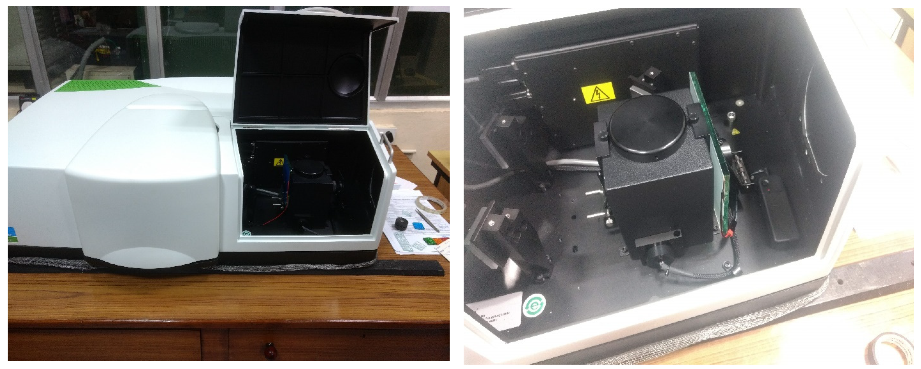
3. Experimental Methodology
4. Design Methodology
5. Cost Assessment Methodology
6. Results and Discussions
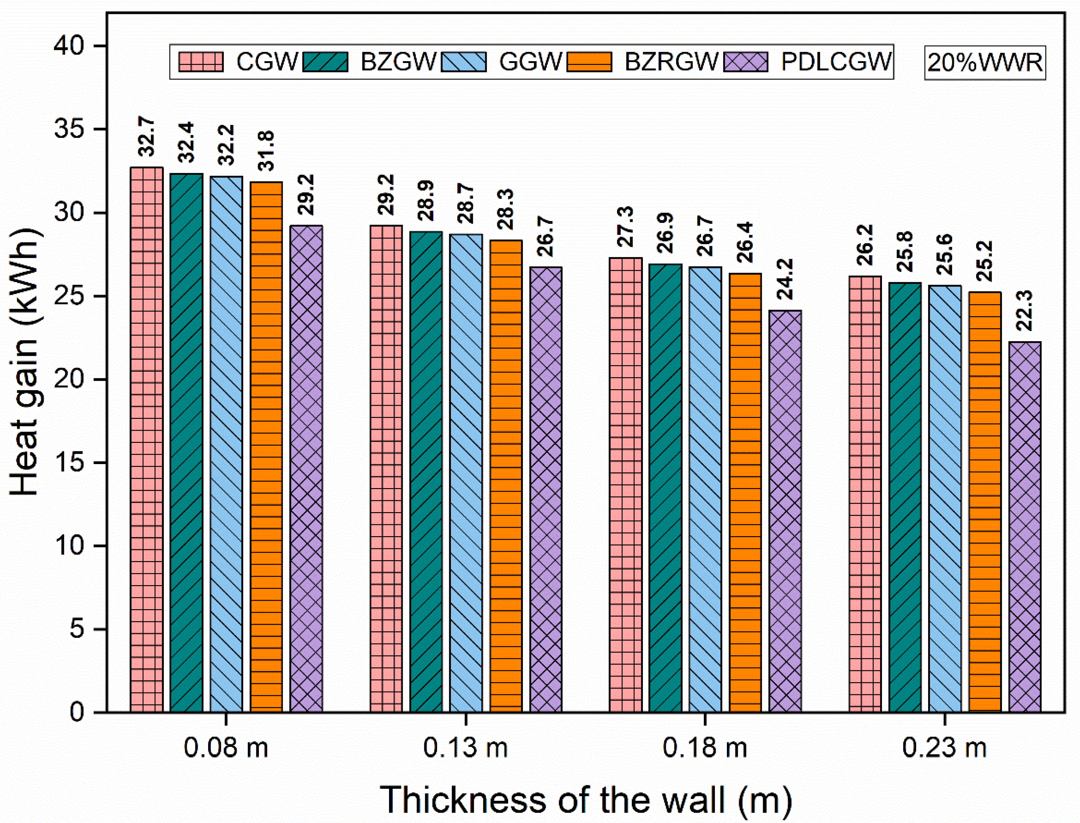
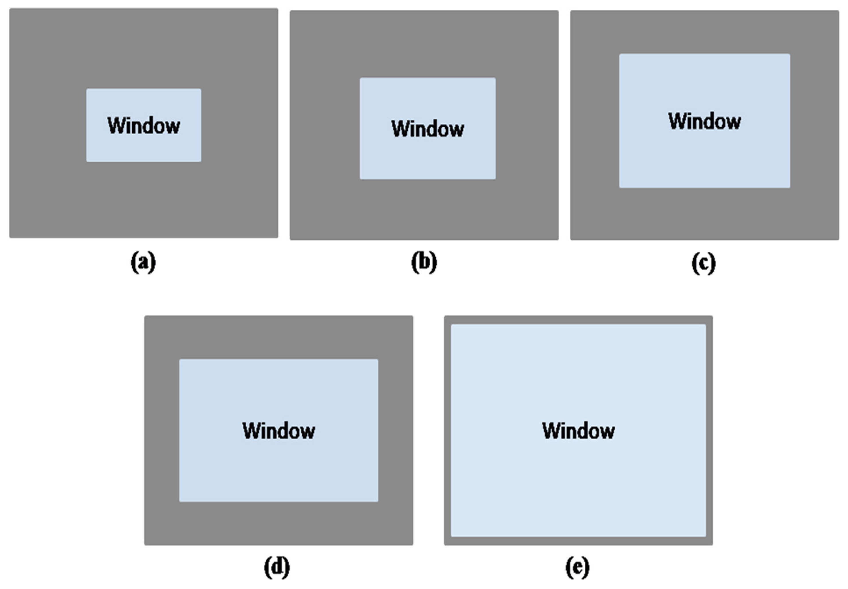
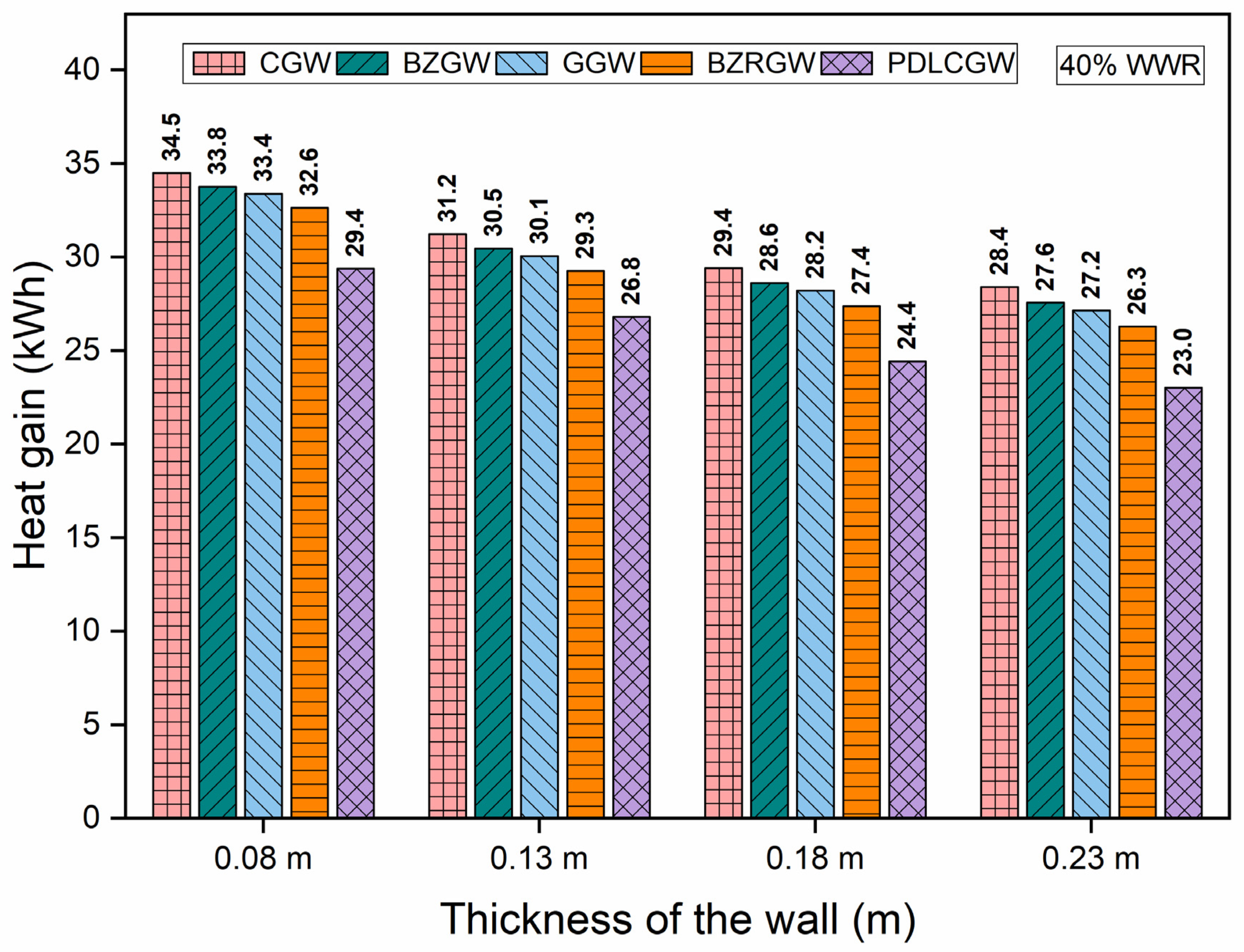
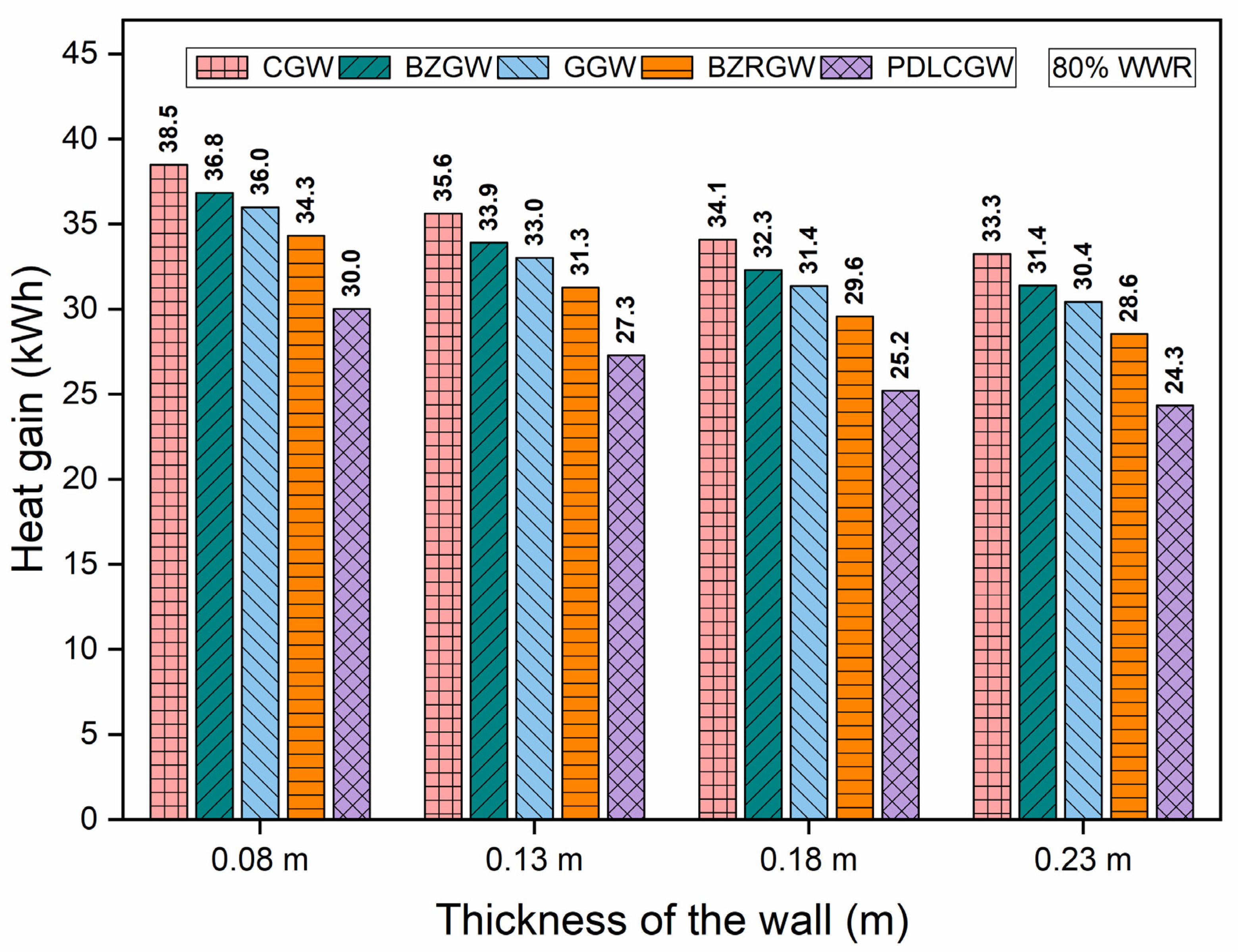
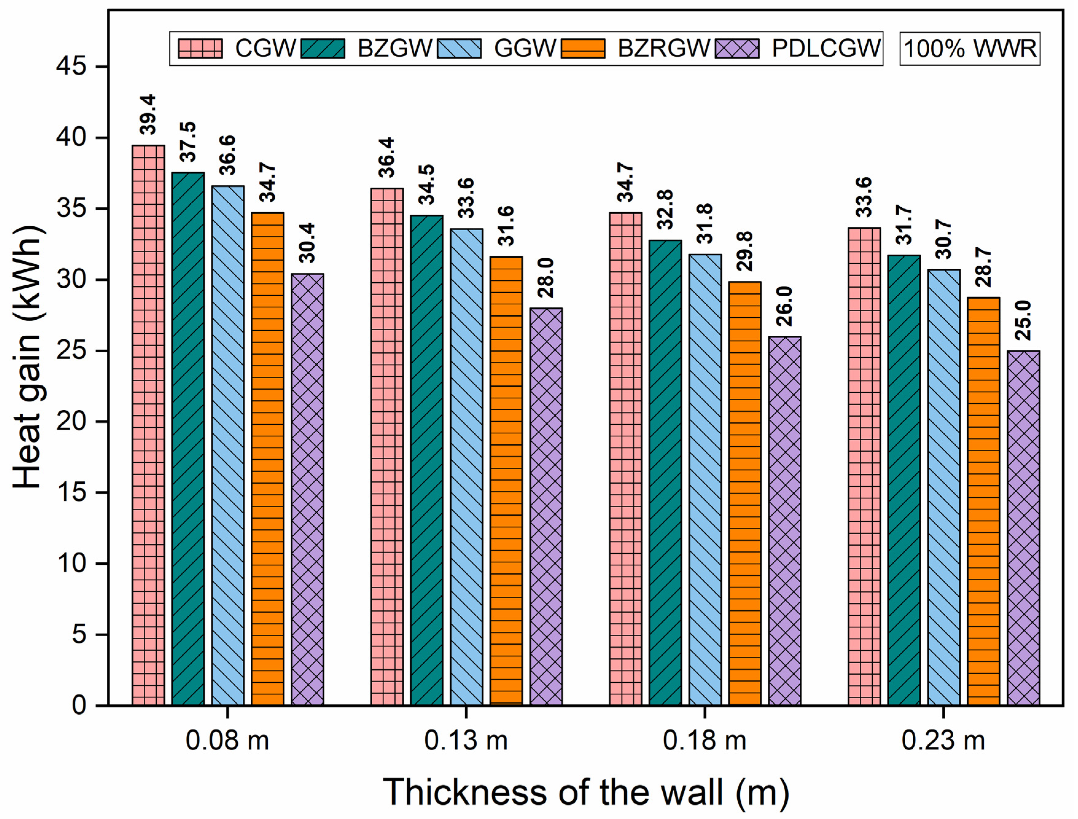
6.1. Effect of Window Glasses and Their WWR on Heat Gain in Laterite Rooms of Various Wall Thicknesses
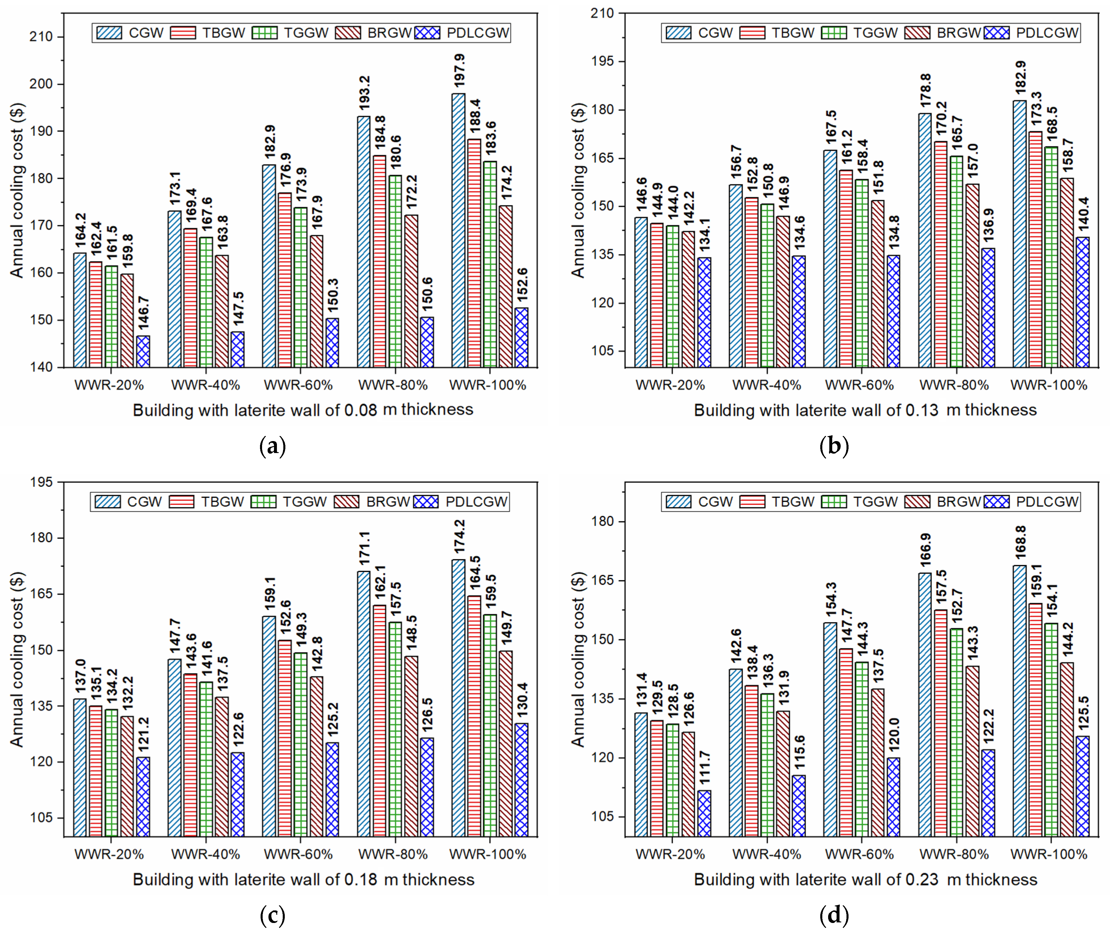
6.2. Influence of Window Glazing, Its WWR, and Wall Thickness on Cooling Costs of Laterite Rooms
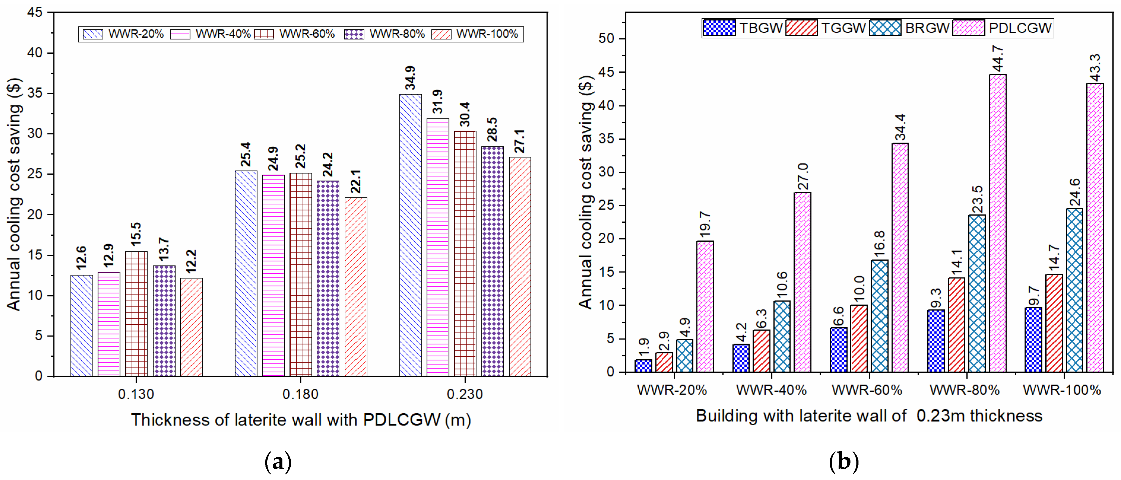
6.3. Influence of Window Glazing, Its WWR, and Wall Thicknesses on Annual Cooling Cost Savings of Laterite Rooms
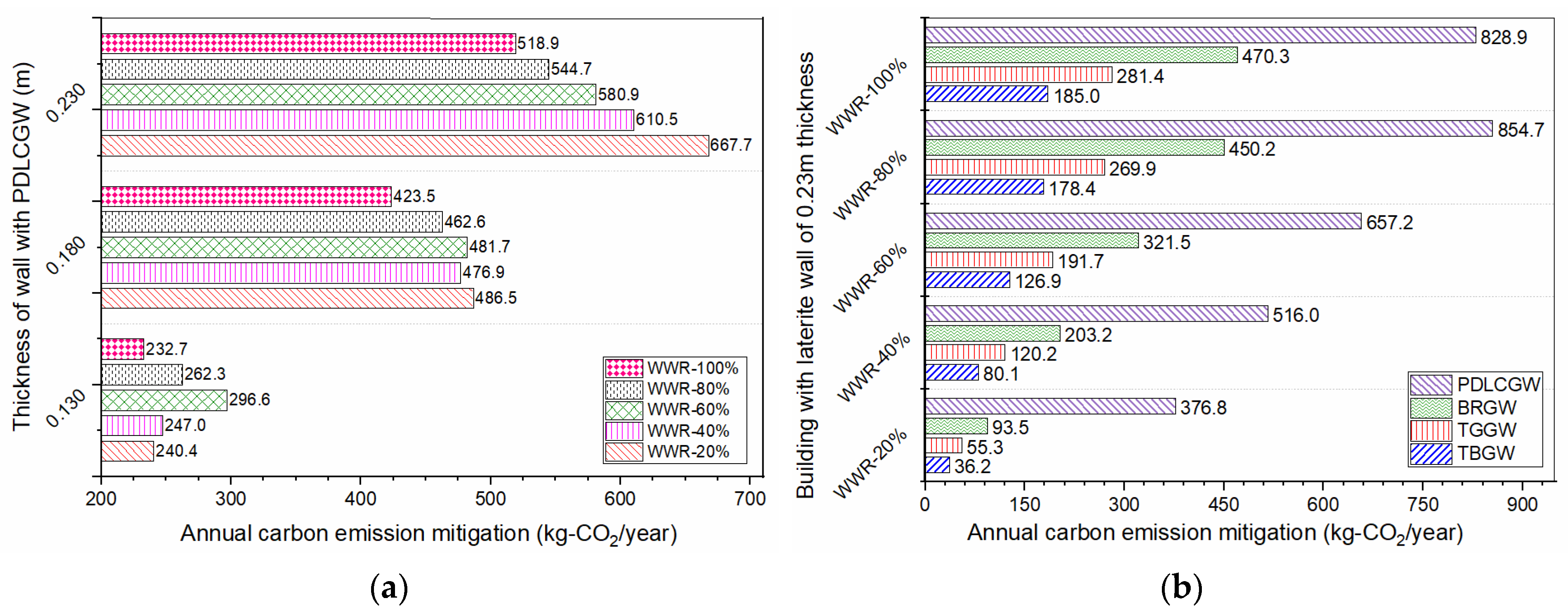
6.4. Influence of Window Glazing, Its WWR, and Wall Thicknesses on Carbon Emission Mitigation in Laterite Rooms
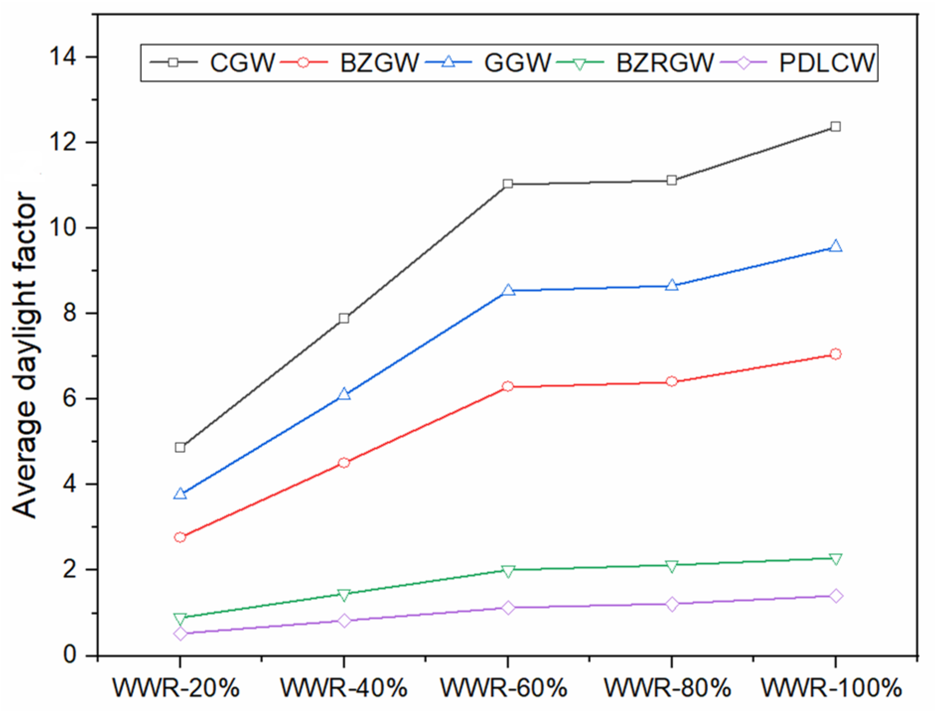
6.5. Influence of Window Glazing and Its WWR on Daylight Inflow in Laterite Rooms
7. Conclusions
- The laterite room of 0.23 m wall thickness with PDLCGW glazing of 40% WWR enhanced cooling cost savings up to USD 31.9 compared to the laterite room of 0.08 m wall thickness with 40% PDLCGW. In addition, the laterite room of 0.23 m wall thickness with PDLCGW glazing of 40% WWR also showed a better cooling cost saving of USD 27.0 compared to 0.23 m wall thickness laterite room of 40% WWR clear glass glazing.
- The laterite room of 0.23 m wall thickness with PDLCGW glazing of 40% WWR showed the enhanced carbon emission mitigation of 610.5 kg-CO2/year compared to the laterite room of 0.08 m wall thickness with 40% PDLCGW. The laterite room of 0.23 m wall thickness with PDLCGW glazing of 40% WWR also showed improved carbon mitigation of 516 kg of CO2/year compared to 0.23 m wall thickness laterite room of 40% WWR with clear glass glazing.
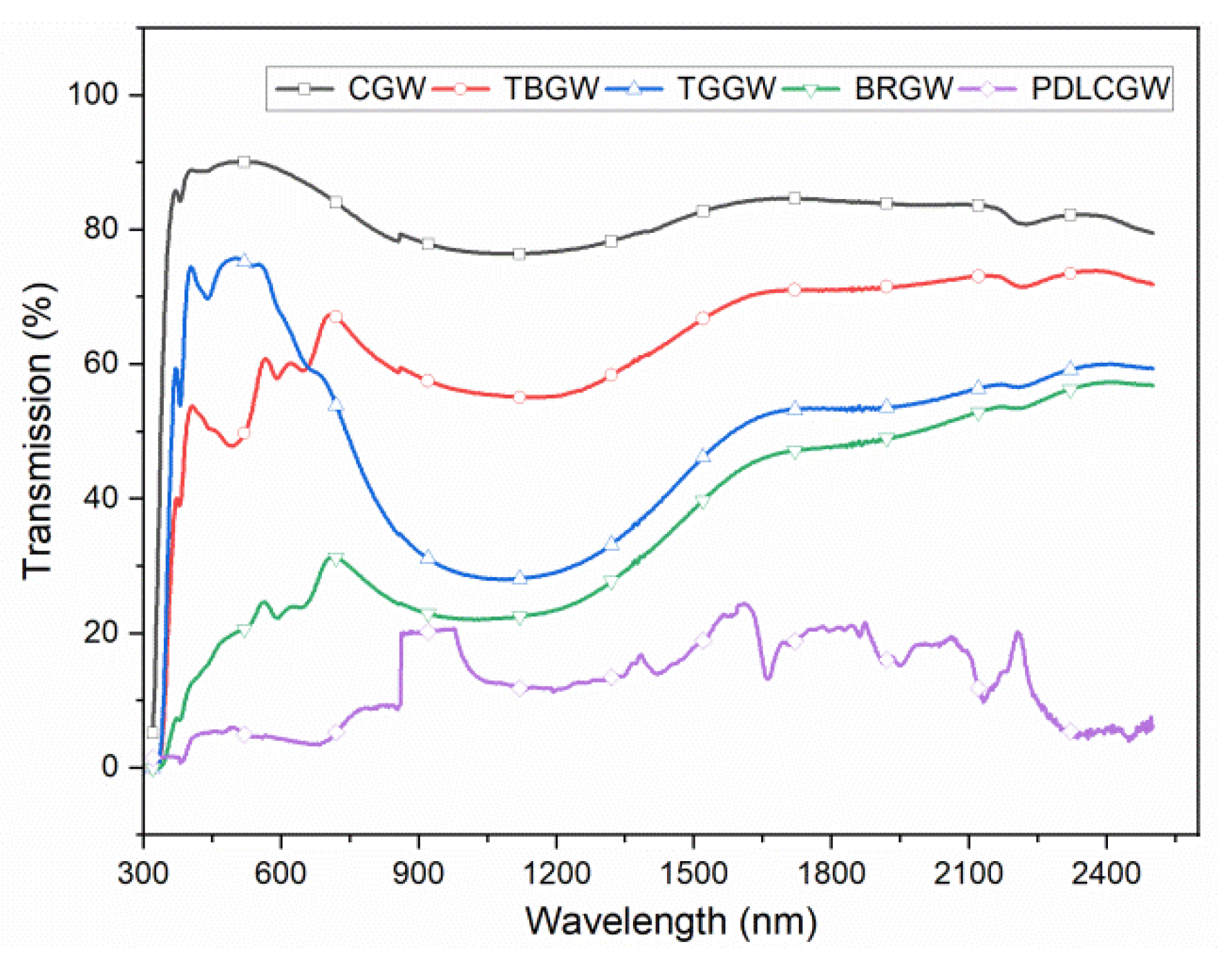
- The energy-efficient order of the glasses for windows was polymer dispersed liquid crystals (PDLCGW), bronze reflective (BRGW), tinted green (TGGW), tinted bronze (TBGW), and clear glass (CGW).
- The simulated daylight factor metrics allowed us to conclude that the studied glasses could access the minimum recommended daylight in building interiors to avoid artificial daylighting for window-to-wall ratios above 40%. The PDLCGW requires a minimum of 40% WWR to access adequate daylight in building interiors in order to avoid artificial daylighting. In addition, the evaluated color rendering properties of the studied glasses assured visual acceptability in the building interiors.
Author Contributions
Funding
Institutional Review Board Statement
Informed Consent Statement
Data Availability Statement
Acknowledgments
Conflicts of Interest
References
- Huang, J.; Lv, H.; Feng, W.; Qu, P.; Huang, Z. Determination of economical thermal insulation thickness for a building wall with two parallel structures. Energy Sources Part A Recover. Util. Environ. Eff. 2020, 42, 399–409. [Google Scholar] [CrossRef]
- ECBC. Energy Conservation Building Code (ECBC): User Guide-Bureau of Energy Efficiency; Bureau of Energy Efficiency: New Delhi, India, 2009; Volume 66.
- GRIHA Manual. Green Rating for Integrated Habitat Assessment; TERI Press: New Delhi, India, 2011. [Google Scholar]
- Albayyaa, H.; Hagare, D.; Saha, S. Energy conservation in residential buildings by incorporating Passive Solar and Energy Efficiency Design Strategies and higher thermal mass. Energy Build. 2019, 182, 205–213. [Google Scholar] [CrossRef]
- Hee, W.J.; Alghoul, M.A.; Bakhtyar, B.; Elayeb, O.; Shameri, M.A.; Alrubaih, M.S.; Sopian, K. The role of window glazing on daylighting and energy saving in buildings. Renew. Sustain. Energy Rev. 2015, 42, 323–343. [Google Scholar] [CrossRef]
- Shaik, S.; Gorantla, K.; Venkata Ramana, M.; Mishra, S.; Kulkarni, K.S. Thermal and cost assessment of various polymer-dispersed liquid crystal film smart windows for energy efficient buildings. Constr. Build. Mater. 2020, 263, 120155. [Google Scholar] [CrossRef]
- Nundy, S.; Ghosh, A. Thermal and visual comfort analysis of adaptive vacuum integrated switchable suspended particle device window for temperate climate. Renew. Energy 2020, 156, 1361–1372. [Google Scholar] [CrossRef]
- Ghosh, A.; Norton, B.; Duffy, A. Effect of atmospheric transmittance on performance of adaptive SPD-vacuum switchable glazing. Sol. Energy Mater. Sol. Cells 2017, 161, 424–431. [Google Scholar] [CrossRef] [Green Version]
- Ghosh, A.; Norton, B.; Duffy, A. Effect of sky clearness index on transmission of evacuated (vacuum) glazing. Renew. Energy 2017, 105, 160–166. [Google Scholar] [CrossRef] [Green Version]
- Ghosh, A.; Norton, B.; Mallick, T.K. Influence of atmospheric clearness on PDLC switchable glazing transmission. Energy Build. 2018, 172, 257–264. [Google Scholar] [CrossRef]
- Ghosh, A.; Norton, B.; Dufy, A. Effect of sky conditions on light transmission through a suspended particle device switchable glazing. Sol. Energy Mater. Sol. Cells 2017, 160, 134–140. [Google Scholar] [CrossRef] [Green Version]
- Wang, T.-P.; Wang, L.-B. A steady heat transfer model of hollow double glazing under entire wave length heat radiation. Energy Build. 2014, 81, 72–83. [Google Scholar] [CrossRef]
- Chand, I.; Kumar, S. Curtailment of Intensity of Solar Radiation Transmission Through Glazing in Buildings at Delhi. Arch. Sci. Rev. 2003, 46, 167–174. [Google Scholar] [CrossRef]
- Baker, N.M.; Taleb, A.M. The Application of the Inclined Window Method for Passive Cooling in Buildings. Arch. Sci. Rev. 2002, 45, 51–55. [Google Scholar] [CrossRef]
- Pal, S.; Roy, B.; Neogi, S. Heat transfer modelling on windows and glazing under the exposure of solar radiation. Energy Build. 2009, 41, 654–661. [Google Scholar] [CrossRef]
- Lai, C.-M.; Wang, Y.-H. Energy-Saving Potential of Building Envelope Designs in Residential Houses in Taiwan. Energies 2011, 4, 2061–2076. [Google Scholar] [CrossRef]
- Mallick, F.H. Thermal comfort and building design in the tropical climates. Energy Build. 1996, 23, 161–167. [Google Scholar] [CrossRef]
- Shaik, S.; Gorantla, K.K.; Setty, A.B.T.P. Investigation of Building Walls Exposed to Periodic Heat Transfer Conditions for Green and Energy Efficient Building Construction. Procedia Technol. 2016, 23, 496–503. [Google Scholar] [CrossRef] [Green Version]
- Yarbrough, D.W.; Anderson, R.W. Use of Radiation Control Coatings to Reduce Building Air-Conditioning Loads. Energy Sources 1993, 15, 59–66. [Google Scholar] [CrossRef]
- Wang, X.; Kendrick, C.; Ogden, R.; Baiche, B.; Walliman, N. Thermal modelling of an industrial building with solar reflective coatings on external surfaces: Case studies in China and Australia. J. Build. Perform. Simul. 2012, 5, 199–207. [Google Scholar] [CrossRef]
- Taleb, A.; Al-Wattar, A. Design of windows to reduce solar radiation transmittance into buildings. Sol. Wind. Technol. 1988, 5, 503–515. [Google Scholar] [CrossRef]
- Singh, I.; Bansal, N.K. Thermal and optical parameters for different window systems in India. Int. J. Ambient. Energy 2002, 23, 201–211. [Google Scholar] [CrossRef]
- Kurekci, N.A. Determination of optimum insulation thickness for building walls by using heating and cooling degree-day values of all Turkey’s provincial centers. Energy Build. 2016, 118, 197–213. [Google Scholar] [CrossRef]
- Feng, W.; Huang, J.; Lv, H.; Guo, D.; Huang, Z. Determination of the economical insulation thickness of building envelopes simultaneously in energy-saving renovation of existing residential buildings. Energy Sources Part A Recover. Util. Environ. Eff. 2018, 41, 665–676. [Google Scholar] [CrossRef]
- Kayfeci, M.; Keçebaş, A.; Gedik, E. Determination of optimum insulation thickness of external walls with two different methods in cooling applications. Appl. Therm. Eng. 2013, 50, 217–224. [Google Scholar] [CrossRef]
- Gülten, A. Determination of optimum insulation thickness using the entransy based thermoeconomic and environmental analysis: A case study for Turkey. Energy Sources Part A Recover. Util. Environ. Eff. 2020, 42, 219–232. [Google Scholar] [CrossRef]
- Ucar, A. Thermoeconomic analysis method for optimization of insulation thickness for the four different climatic regions of Turkey. Energy 2010, 35, 1854–1864. [Google Scholar] [CrossRef]
- Cuce, E.; Cuce, P.M.; Wood, C.; Riffat, S.B. Optimizing insulation thickness and analysing environmental impacts of aerogel-based thermal superinsulation in buildings. Energy Build. 2014, 77, 28–39. [Google Scholar] [CrossRef]
- Yang, Q.; Liu, M.; Shu, C.; Mmereki, D.; Hossain, U.; Zhan, X. Impact Analysis of Window-Wall Ratio on Heating and Cooling Energy Consumption of Residential Buildings in Hot Summer and Cold Winter Zone in China. J. Eng. 2015, 2015, 538254. [Google Scholar] [CrossRef] [Green Version]
- Inanici, M.N.; Demirbilek, F. Thermal performance optimization of building aspect ratio and south window size in five cities having different climatic characteristics of Turkey. Build. Environ. 2000, 35, 41–52. [Google Scholar] [CrossRef]
- Goia, F. Search for the optimal window-to-wall ratio in office buildings in different European climates and the implications on total energy saving potential. Sol. Energy 2016, 132, 467–492. [Google Scholar] [CrossRef]
- Gorantla, K.; Shaik, S.; Setty, A.B.T.P. Effect of Different Double Glazing Window Combinations on Heat gain in Buildings for Passive Cooling in Various Climatic Regions of India. Mater. Today Proc. 2017, 4, 1910–1916. [Google Scholar] [CrossRef]
- KiranKumar, G.; Saboor, S.; Babu, T.A. Thermal Analysis of Wall and Window Glass Materials for Cooling Load Reduction in Green Energy Building Design. Mater. Today Proc. 2017, 4, 9514–9518. [Google Scholar] [CrossRef]
- Kirankumar, G.; Saboor, S.; Babu, T.A. Investigation of Different Window and Wall Materials for Solar Passive Building Design. Procedia Technol. 2016, 24, 523–530. [Google Scholar] [CrossRef] [Green Version]
- Maduru, V.R.; Shaik, S. Laminated glazing for buildings: Energy saving, natural daylighting, and CO2 emission mitigation prospective. Environ. Sci. Pollut. Res. 2021, 1–17. [Google Scholar] [CrossRef] [PubMed]
- Ramana, M.V.; Saboor, S. A novel glazing system filled with hydrogel granules: Energy saving, diurnal illumination, color rendering, and CO2 emission mitigation prospective. Energy Sources Part A Recover. Util. Environ. Eff. 2021, 1–16. [Google Scholar] [CrossRef]
- Kirankumar, G.; Saboor, S.; Vali, S.S.; Mahapatra, D.; Setty, A.B.T.P.; Kim, K.-H. Thermal and cost analysis of various air filled double glazed reflective windows for energy efficient buildings. J. Build. Eng. 2020, 28, 101055. [Google Scholar] [CrossRef]
- Ozel, M. Impact of glazing area on the thermal performance of buildings. Int. J. Ambient. Energy 2020, 1–17. [Google Scholar] [CrossRef]
- Saboor, S.; Ashok Babu, T.P. Influence of Ambient Air Relative Humidity and Temperature on Thermal Properties and Unsteady Thermal Response Characteristics of Laterite Wall Houses. Build. Environ. 2016, 99, 170–183. [Google Scholar] [CrossRef]
- Gidigasu, M. Degree of weathering in the identification of laterite materials for engineering purposes—A review. Eng. Geol. 1974, 8, 213–266. [Google Scholar] [CrossRef]
- Kasthurba, A.K.; Reddy, K.R.; Venkat Reddy, D. Use of Laterite as a sustainable building material in developing countries. Int. J. Earth. Sci. Eng. 2014, 7, 1251–1258. [Google Scholar]
- Kasthurba, A.; Santhanam, M.; Mathews, M. Investigation of laterite stones for building purpose from Malabar region, Kerala state, SW India—Part 1: Field studies and profile characterisation. Constr. Build. Mater. 2007, 21, 73–82. [Google Scholar] [CrossRef]
- Kasthurba, A.; Santhanam, M.; Achyuthan, H. Investigation of laterite stones for building purpose from Malabar region, Kerala, SW India—Chemical analysis and microstructure studies. Constr. Build. Mater. 2008, 22, 2400–2408. [Google Scholar] [CrossRef]
- SP:41(S&T). Handbook on Functional Requirement of Buildings Other than Industrial Buildings; Bureau of Indian Standards: New Delhi, India, 1987; pp. 33–40.
- ASTM E424-71. Test for Solar Energy Transmittance and Reflectance (Terrestrial) of Sheet Materials; ASTM: Washington, DC, USA, 2015; pp. 1320–1326. [Google Scholar]
- Davies, M. The thermal admittance of layered walls. Build. Sci. 1973, 8, 207–220. [Google Scholar] [CrossRef]
- Pipes, L.A. Matrix analysis of heat transfer problems. J. Frankl. Inst. 1957, 263, 195–206. [Google Scholar] [CrossRef]
- Kumar, K.G.; Saboor, S.; Kumar, V.; Kim, K.H.; Babu, T.P.A. Experimental and theoretical studies of various solar control window glasses for the reduction of cooling and heating loads in buildings across different climatic regions. Energy Build. 2018, 173, 326–336. [Google Scholar] [CrossRef]
- Mani, A.; Rangarajan, S. Solar Radiation over India; Allied Publishers Private Limited: New Delhi, India, 1982. [Google Scholar]
- ASHRAE. ASHRAE Handbook of Fundamentals; ASHRAE: Atlanta, GA, USA, 2001. [Google Scholar]
- CIBSE. Guide A: Environmental Design; The Chartered Institution of Building Service Engineers: London, UK, 2006; ISBN 10-1-903287-66-9. [Google Scholar]
- Saboor, S.; Chelliah, A.; Gorantla, K.K.; Kim, K.-H.; Lee, S.-H.; Shon, Z.H.; Brown, R.J. Strategic design of wall envelopes for the enhancement of building thermal performance at reduced air-conditioning costs. Environ. Res. 2021, 193, 110577. [Google Scholar] [CrossRef] [PubMed]
- Arumugam, C.; Shaik, S. Transforming waste disposals into building materials to investigate energy savings and carbon emission mitigation potential. Environ. Sci. Pollut. Res. 2021, 28, 15259–15273. [Google Scholar] [CrossRef] [PubMed]
- IS 2440. Guide for Daylighting of Buildings. Indian Standard; Bureau of Indian Standards: New Delhi, India, 2008.


| Materials/Properties | k (W/mK) | Cp (J/kgK) | ρ (kg/m3) |
|---|---|---|---|
| Laterite stone | 1.3698 | 1926.1 | 1000 |
| Dense concrete | 1.74 | 880 | 2410 |
| RCC | 1.58 | 880 | 2288 |
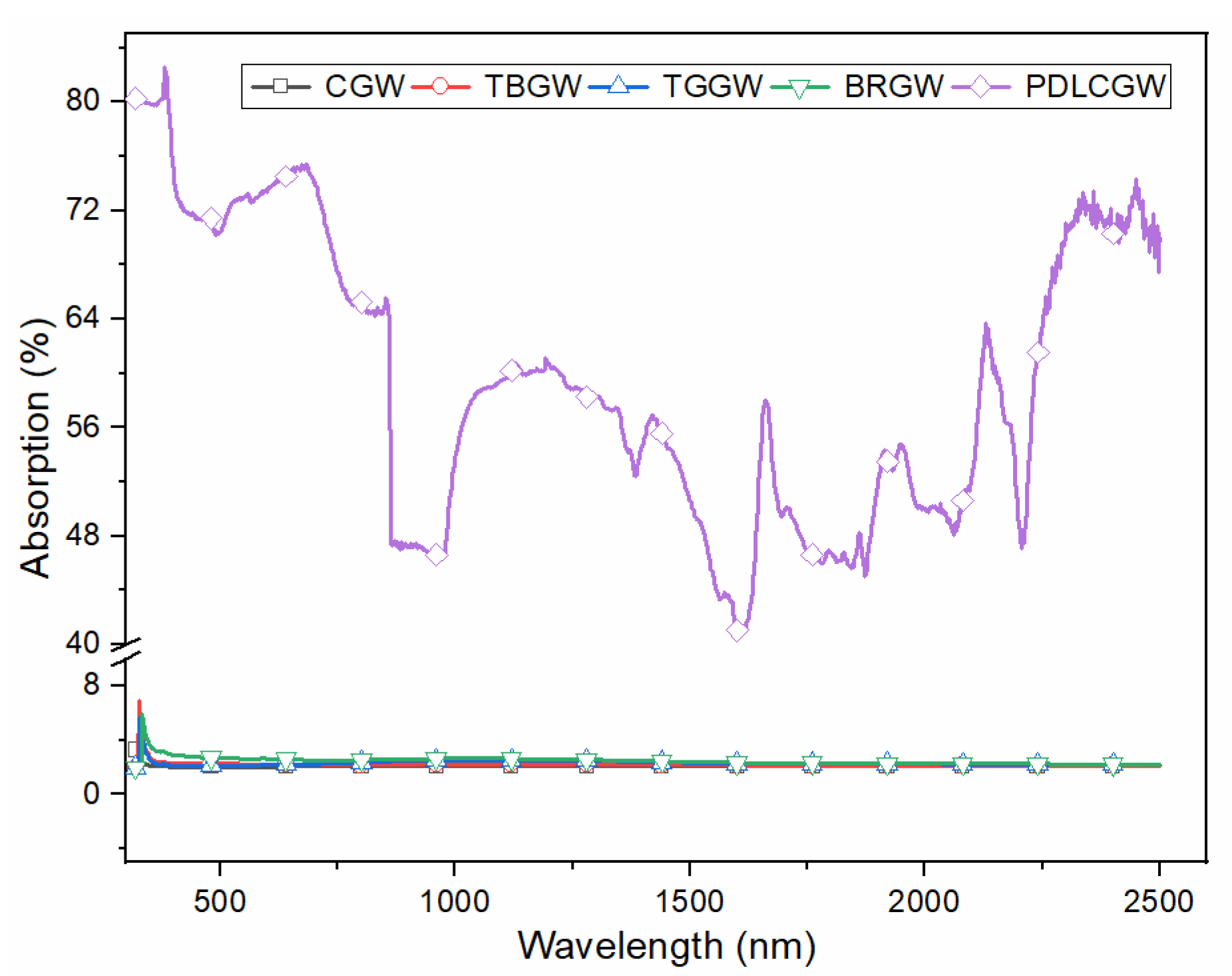
| Window/Solar Properties | Abbreviation | Transmission, TSOL (%) | Reflection, RSOL (%) | Absorption, ASOL (%) | CRI (−) | CCT (K) |
|---|---|---|---|---|---|---|
| Clear glass window | CGW | 81.84 | 16.06 | 2.08 | 95.7 | 5188 |
| Tinted bronze glass window | TBGW | 58.66 | 39.08 | 2.24 | 84.8 | 5114 |
| Tinted green glass window | TGGW | 47.32 | 50.32 | 2.53 | 82.5 | 5240 |
| Bronze reflective glass window | BRGW | 27.22 | 70.17 | 2.60 | 85.1 | 5375 |
| Polymer dispersed liquid crystals glass window | PDLCGW | 11 | 27 | 62 | 86.8 | 5471 |
| Enclosure | CGW (kWh) | TBGW (kWh) | TGGW (kWh) | BRGW (kWh) | PDLCGW (kWh) | |
|---|---|---|---|---|---|---|
| Walls | 1551.2 | 1596.9 | 1619.7 | 1665.3 | 1520.8 | |
| WWR-20% | Floor | 62.4 | 65.4 | 65.4 | 66.9 | 60.8 |
| Roof | 1815.9 | 1840.2 | 1853.9 | 1881.3 | 1748.9 | |
| Window | 577.9 | 447.1 | 380.2 | 244.9 | 76 | |
| Total | 4007.4 | 3949.6 | 3919.2 | 3858.3 | 3406.6 | |
| Walls | 1371.8 | 1458.5 | 1504.1 | 1593.8 | 1444.8 | |
| WWR-40% | Floor | 57.8 | 60.8 | 62.4 | 65.4 | 68.4 |
| Roof | 1726.1 | 1777.8 | 1805.2 | 1858.4 | 1878.2 | |
| Window | 1190.8 | 921.6 | 783.2 | 504.9 | 132.3 | |
| Total | 4346.5 | 4218.8 | 4154.9 | 4022.6 | 3523.7 | |
| Walls | 1201.4 | 1326.2 | 1391.6 | 1522.3 | 1522.3 | |
| Floor | 51.7 | 56.3 | 59.3 | 63.9 | 68.4 | |
| WWR-60% | Roof | 1634.9 | 1714 | 1753.5 | 1835.6 | 1878.2 |
| Window | 1817.4 | 1406.8 | 1195.4 | 771.1 | 188.6 | |
| Total | 4705.4 | 4503.1 | 4399.7 | 4192.9 | 3657.6 | |
| Walls | 1049.4 | 1207.5 | 1289.7 | 1456.9 | 1475.2 | |
| WWR-80% | Floor | 47.1 | 53.2 | 56.3 | 62.4 | 68.4 |
| Roof | 1548.2 | 1651.6 | 1704.8 | 1812.8 | 1901 | |
| Window | 2442.4 | 1890.4 | 1606 | 1037.2 | 279.8 | |
| Total | 5087.1 | 4802.7 | 4656.8 | 4369.3 | 3724.5 | |
| Walls | 1026.6 | 1190.8 | 1274.4 | 1446.3 | 1444.8 | |
| Floor | 45.6 | 53.2 | 56.3 | 62.4 | 68.4 | |
| WWR-100% | Roof | 1536 | 1642.5 | 1697.2 | 1809.8 | 1901 |
| Window | 2538.2 | 1964.9 | 1669.9 | 1078.3 | 410.6 | |
| Total | 5146.5 | 4851.4 | 4697.8 | 4396.7 | 3824.9 |
Publisher’s Note: MDPI stays neutral with regard to jurisdictional claims in published maps and institutional affiliations. |
© 2021 by the authors. Licensee MDPI, Basel, Switzerland. This article is an open access article distributed under the terms and conditions of the Creative Commons Attribution (CC BY) license (https://creativecommons.org/licenses/by/4.0/).
Share and Cite
Shaik, S.; Gorantla, K.; Ghosh, A.; Arumugam, C.; Maduru, V.R. Energy Savings and Carbon Emission Mitigation Prospective of Building’s Glazing Variety, Window-to-Wall Ratio and Wall Thickness. Energies 2021, 14, 8020. https://doi.org/10.3390/en14238020
Shaik S, Gorantla K, Ghosh A, Arumugam C, Maduru VR. Energy Savings and Carbon Emission Mitigation Prospective of Building’s Glazing Variety, Window-to-Wall Ratio and Wall Thickness. Energies. 2021; 14(23):8020. https://doi.org/10.3390/en14238020
Chicago/Turabian StyleShaik, Saboor, Kirankumar Gorantla, Aritra Ghosh, Chelliah Arumugam, and Venkata Ramana Maduru. 2021. "Energy Savings and Carbon Emission Mitigation Prospective of Building’s Glazing Variety, Window-to-Wall Ratio and Wall Thickness" Energies 14, no. 23: 8020. https://doi.org/10.3390/en14238020
APA StyleShaik, S., Gorantla, K., Ghosh, A., Arumugam, C., & Maduru, V. R. (2021). Energy Savings and Carbon Emission Mitigation Prospective of Building’s Glazing Variety, Window-to-Wall Ratio and Wall Thickness. Energies, 14(23), 8020. https://doi.org/10.3390/en14238020