Article

Energy Efficiency and Limitations of the Methods of Controlling the Hydraulic Cylinder Piston Rod under Various Load Conditions

Institute of Machine Tools and Production Engineering, Lodz University of Technology, Stefanowskiego 1/15 Street, 90-924 Lodz, Poland
*
Author to whom correspondence should be addressed.
Energies 2021, 14(23), 7973; https://doi.org/10.3390/en14237973
Submission received: 19 October 2021 / Revised: 18 November 2021 / Accepted: 24 November 2021 / Published: 29 November 2021

Abstract

:
The article is an overview of various methods of braking and controlling the movement of the piston rod under various load conditions. The purpose of this review is to systematize the state of the art in terms of efficiency, energy consumption and limitations of each method. The article discusses systems with different types of hydraulic actuators, operating under passive, active and variable load during the duty cycle of the piston rod. The existing literature was analysed in terms of applicability, reduction of energy consumption of the systems and even the possibility of energy return. Attention was paid to the costs and the need for additional power sources, as well as the problems and limitations of the presented methods. Based on the simulation model, energy consumption tests were carried out in systems with an actuator loaded with a variable force. There is a comparison of all methods in terms of actuator type, load, energy consumption and the possibility of energy recovery.

1. Introduction

Hydraulic actuators are machines whose task is to convert the energy of a fluid into mechanical energy. The piston–piston rod assembly in the actuator usually performs reciprocating (less frequently rotating) motion. The stroke (or the angle of rotation) is a parameter of limited value, hence the need to ensure an effective return movement. In single-acting actuators, it can occur either by the spring force or the gravity force (Figure 1), depending on the position of the actuator (horizontal or vertical).
In double-acting actuators, there is a need to power both cylinder chambers to allow movement in both directions. Directional valves are most often used for this purpose [1]. These actuators are used where it is necessary to use a force acting in two directions. The hydraulic medium can be supplied to the chambers through holes in the piston rod or directly into the cylinder interior. Double-acting actuators may be available in variants with a one-sided or a double-sided piston rod (Figure 2).
In one-sided piston rod actuators, the cross-sectional area of the piston rod face is smaller than the cross-sectional area of the cylinder bottom—the force pushing the piston rod out is greater than the force returning it (assuming the same pressure). In double-sided piston rod actuators, the piston rod is attached to both sides of the piston. If the working fluid is supplied to one of the cylinder chambers—the piston rod retracts on that side, and on the other side—it extends outside the cylinder. Because of an equally effective cross-sectional area of the piston face on both sides, a given flow causes the same rates of extension and retraction speeds [2].
The key issue for the durability and reliability of the hydraulic system is the selection of an appropriate power supply and control system. This is important to ensure the uniformity of the working movements in the actuator. Its lack may result, among others, from changing the value and direction of the load applied to the element. This usually has a significant impact on the failure-free operation of the system and its components as well as on the safety of its use [3,4].
The piston rod is one of the most loaded elements of the cylinder. It must transfer tensile or compressive forces and avoid bending. Additionally, there is also the issue of buckling, which in practice is responsible for the most frequent failures of the piston rod [5]. The maximum value of the supply pressure results from the setting of the pressure relief valve. The supply pressure is usually lower than the pump working pressure due to the presence of hydraulic resistance in the system [6].
The force acting on the piston rod in the single-acting actuator (or a double-acting actuator with a double-sided piston rod) can be determined by the formula:
F =   A     p
where A—the cross-sectional working area of the piston, p—actuator supply pressure. The same dependency can be used for (Figure 3a).
In the case of double-acting actuators with a single-sided piston rod, Formula (1) must be modified with an additional direction of the power source. In this case, to move the piston rod, it is also necessary to overcome the pressure in the second chamber of the cylinder:
F =   A 1     p 1 ± A 2     p 2
where A1, A2—the cross-sectional working area of the double-acting actuator piston sides, p1, p2—actuator supply pressure during two-side movement (Figure 3b).
However, every actuator can be loaded in different ways. Passive load is when the direction of the force is opposite to the direction of movement of the piston rod (Figure 4a). In this case, the supply pressure must be built up in the appropriate chamber to move the piston rod. An active load occurs when a gravity force causes the piston rod to move unwantedly (Figure 4b). In this case, it is required to counteract the movement of the piston rod. This is especially the case with single-acting actuators when the return occurs spontaneously under the influence of gravity or a spring. In the case of double-acting actuators, it is very important to properly brake the piston rod. Otherwise, in one of the actuator chambers, cavitation may occur due to negative pressure. There are also machines where both kinds of loads can occur on the piston rod during one actuator cycle (Figure 4c). It is therefore important to select the appropriate method of controlling the actuator.
This paper discusses various methods of controlling the movement of the piston rod of an actuator loaded with passive, active or variable force. The article is organized as follows. Section 2, Section 3 and Section 4 contain a detailed description of methods based on hydraulic cylinder construction, the use of appropriate hydraulic valves and modern electro-hydraulic technology, respectively. Section 5 presents a comparison of the braking methods used in terms of their suitability in systems operating under different piston rod loading conditions. The comparison of energy consumption in methods enabling operation in conditions of variable load is also presented. Finally, conclusions are drawn from the research and the discussion can be found in Section 6.

2. Methods of Cushioning the Piston Overrun

An important issue in the case of actuators is the issue of cushioning piston overrun. Especially for heavy-duty actuators and at high feed rates, there is a risk of the piston hitting the cylinder bottom [5,6]. This phenomenon, in addition to noise, may also damage the cylinder and thus causes a threat to human safety. Moreover, such failures usually generate high costs [7]. It is assumed that the braking is justified for piston speeds greater than 0.1 m/s [5,6]. There are different ways to slow down the movement of the piston towards the end of the stroke. Such actions are mainly limiting the outflow of the working fluid from the cylinder—this causes a change in the pressure situation and creates a force that inhibits the piston overrun [7,8].

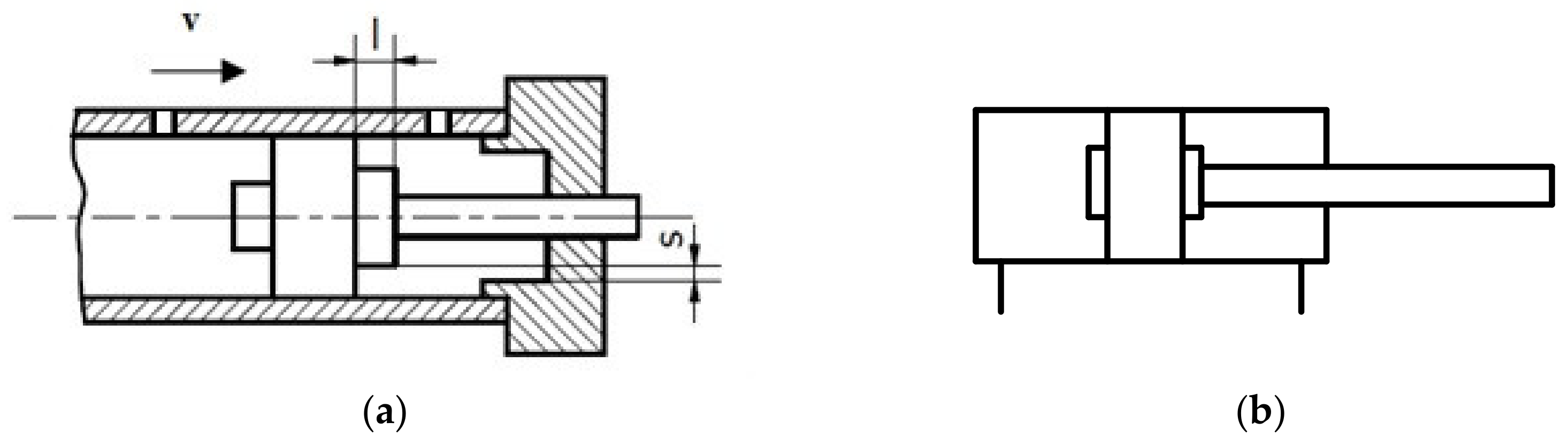
2.1. Cushioning with Annular Clearance Method (Braking Gap)

Cushioning with the braking gap is one of the simplest solutions in terms of design. In this solution, there is a pin which is connected to a piston [1,2,3,4,5,6]. During the final phase of the piston movement in a given direction, the pin is introduced into an additional slot in the cylinder bottom.
As a result of a loose fit, a gap of thickness s is formed (Figure 5a). The braking of the piston with the speed v occurs along the path marked as l.
During braking, the pressure system changes so much that it creates a damping force Ft. This force balances the kinetic energy associated with the movement of the piston and can be calculated from the equation resulting from the principle of conservation of energy [9]:
F t = m     v 2 2     l
where m—the mass of the system related to the piston, v—piston speed.
In the example given, the pin connected to the piston has the shape of a cylinder. Sometimes there are also other shaped solutions, f. ex. a conical pin [10].

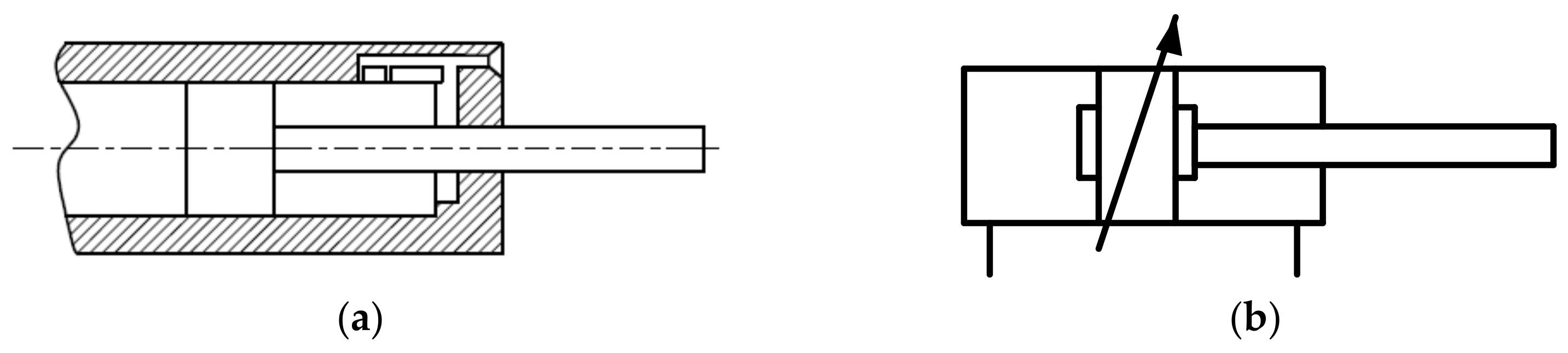
2.2. Cushioning with the Orifice Method

The orifice method allows to create a force that slows down the piston through a series of holes in the cylinder pipe of the actuator. As the piston approaches the end of the movement phase, successive holes are closed (covered)—this delays the outflow of fluid from the chamber and reduces the overrun speed and so-called cushioning occurs [7]. The scheme and a hydraulic symbol of this method is shown in Figure 6.

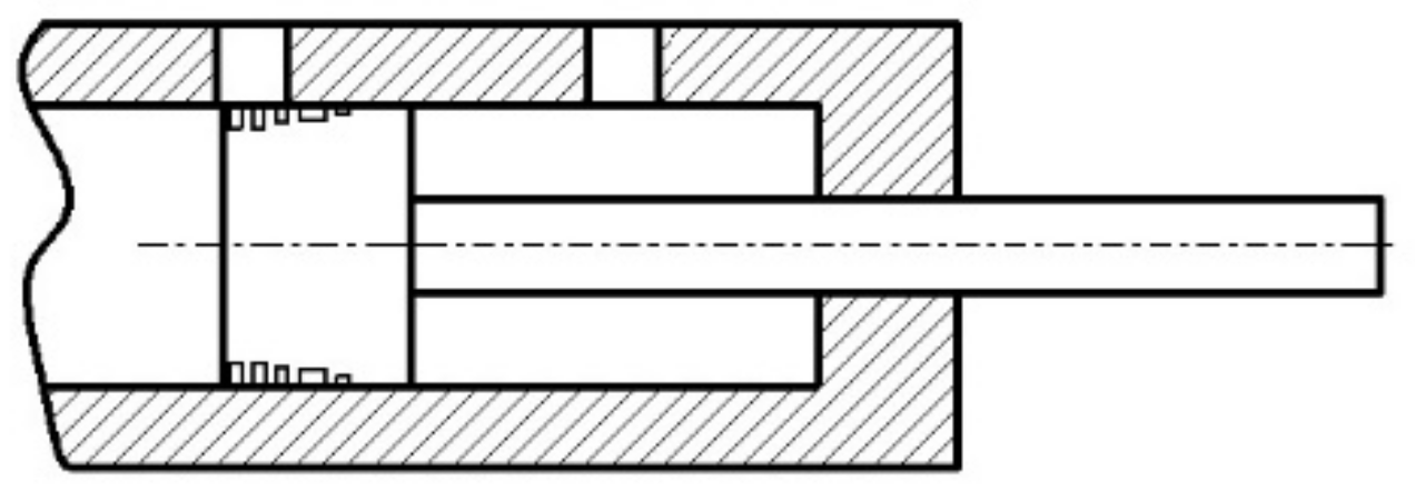
2.3. Cushioning Using the Piston Groove Method

Castilla et al. [11] presents the method of braking the piston rod with the use of a piston with cut grooves. The principle of operation is similar to that of the orifice method. These grooves are responsible for the flow rate of the working fluid and the pressure drop in the cylinder. The scheme of this method is shown in Figure 7.
These three types of braking can be used with both passive and active loads. However, with an active load, additional protection is needed to prevent the sudden acceleration of the piston rod. Therefore, a flow control valve [7,8] should be additionally used for precise control of the working fluid flow.

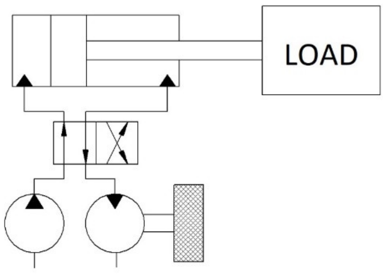
2.4. Braking with a Flywheel

The flywheel has long been used to reduce dynamics in systems of rotary machines. Properly selecting its size can be a good way to brake actively loaded drives. This solution also works well with varying forces acting on the machine. It is also possible to use a flywheel in hydrostatic systems with a single-acting and double-acting actuator. It is necessary to install a hydraulic motor with a mounted flywheel. The fluid from the actuator must overcome the torque of the hydraulic motor coming from the flywheel. Many articles deal with this topic due to the possibility of energy recovery. It is enough for the hydraulic motor to connect to the generator instead of the flywheel. An extension of this method is the use of a frequency inverter, which was described in this paper in Section 4.2.
Flywheel energy storage systems (FESS) (Figure 8) are widely used in transportation, engineering, energy industry, and even space industry [12,13]. A typical FESS consists of a spinning element (flywheel) which is contained in a tank with a lower pressure. This pressure reduces the resistance to rotation, which allows the flywheel to rotate longer. FESS is capable of storing energy in this rotating mass and the kinetic energy is stored as rotational energy [13].
The energy generated during braking can be stored. Schmidt et al. [14], the issue of energy storage in self-locking variable speed hydraulic drives is described. The specific application of FESS in hydraulic excavators is discussed in [15,16,17]. In excavators, while the boom falls, a large amount of energy is converted into heat. The flywheel acted as an energy storage element, while the hydraulic pump motor served to convert the energy. The proposed solution was able to recover the potential energy of the boom, as well as regenerate the flow by introducing an additional valve. The use of this valve allowed for an efficiency improvement of 13% compared to the FESS without the valve. A review of the possibilities of energy recovery systems for hybrid hydraulic excavators is described in detail by Do et al. [17].

3. Valve Methods for Controlling the Movement of the Actuator Piston Rod

Depending on the load on the piston rod, different valves are used to influence its operating speed. The valves prevent the rapid falling of heavy load due to gravity or overrunning. Some of them can also control the speed of the piston, depending on the needs of the operator. The most used valves are presented below, with an overview of their possible applications for various variants of the piston rod load.

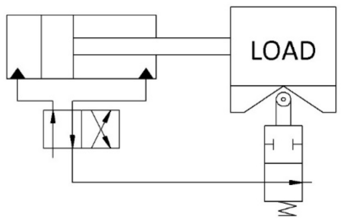
3.1. Braking with the Deceleration Valve Method

The release valve (Figure 9) is a valve that changes the flow surface area, thanks to which it is possible to control the flow (its increase or decrease) [8]. The design of this valve requires the use of a special cam that allows the valve to be activated when the piston approaches the bottom of the actuator. Then, the flow of the working fluid to the cylinder decreases, and the piston rod slows down. This solution can be used in all possible actuators with different load directions. Similar to the previous methods, it often comes with additional flow throttling valves. This is a non-energetic method of braking as the pressure builds up and energy is lost to heat. In some applications, the pusher in the system may be designed so that it is possible to change the speed of the actuator piston [7,8]. They are most often found in old-style machine tools and are not popular today. Currently, a similar task is performed by proportional valves and servo valves.

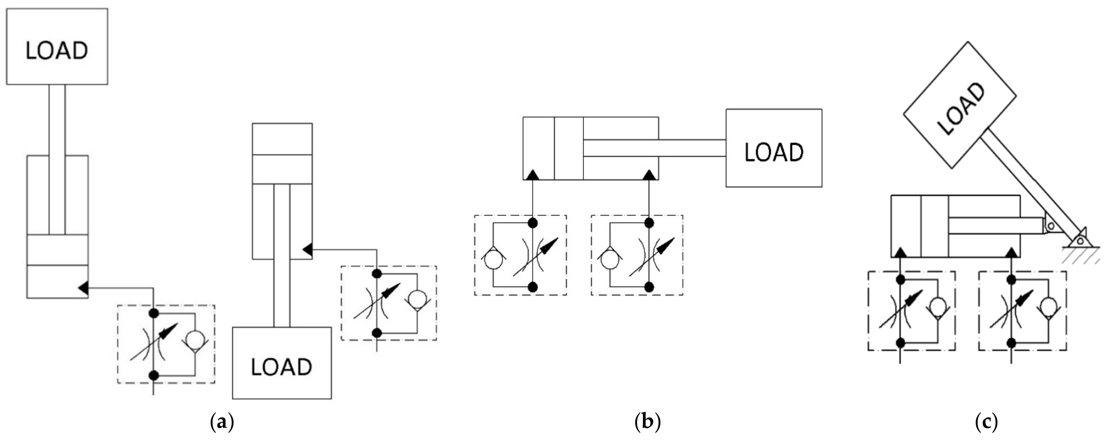
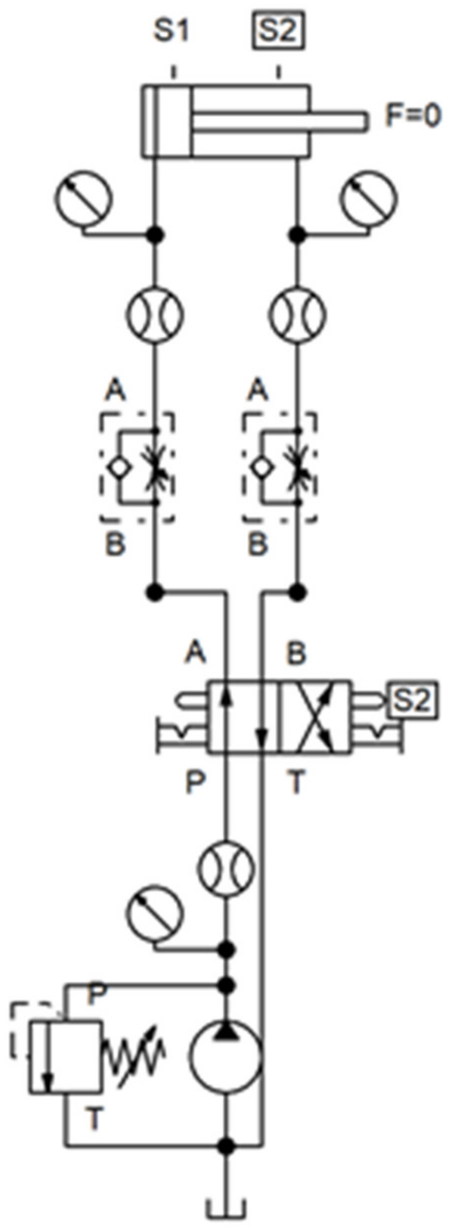
3.2. Braking through a Throttle Check Valve with an Adjustable Gap Size

In hydraulic systems, there is often a combination of throttle and check valves. In the case of double-acting actuators, the piston moving to one of the cylinder ends causes the fluid to be forced out of the working chamber. If the fluid cannot leave the chamber, the piston will stop. Similarly, if the flow reduction is only partial—the piston speed will decrease [8]. Hence, the need for a throttle valve, which reduces the speed of fluid outflow from the working chamber—as a result, the piston-rod assembly slows down. This valve can be set by changing the width of the created gap. The combination of a throttle valve with a check valve makes it possible to ensure free flow in one direction and controlled flow in the other one [18,19,20]. Unfortunately, braking with such a valve only applies when the piston rod is loaded in one direction. Therefore, it is important to position the valve correctly, depending on the actuator used. In single-acting actuators, the throttle check valve is always used in the throttle direction opposite to the acting force (Figure 10a). In double-acting cylinders, operating in a horizontal position, where a passive force is applied in both directions of movement, a throttle valve can be applied meter-out (Figure 10b) or meter-in (Figure 10c). These two only serve to reduce the speed of the piston rod, not the actual braking [21,22]. However, the use of two such valves in meter-out allows controlled movement of the actuator regardless of the direction of its load (Figure 10c). This makes it possible to brake the piston rod when the force changes from passive to active. However, the valve must be adjusted according to the forces involved. At high loads, this solution is not practical due to the need to restrict the flow through the valve to a great extent. This causes an unnecessary build-up of pressure as the force against the piston rod overcomes the force needed to push the fluid through the valve gap. On the other hand, opening the valve too much could lead to a vacuum in one of the chambers of the cylinder due to the operating force.
The throttle check valve is the simplest and cheapest valve used to regulate the flow. Unfortunately, it is susceptible to a change in the force loading of the piston rod. The flow through the orifice of this valve increases in proportion to the loading force. In systems where the force changes during the actuator stroke, the speed of the piston rod will also vary. In this case, a flow control valve is often used to keep the flow constant irrespective of the load (Figure 11). The use of two 2-way flow control valves can be used in meter-out and control the load regardless of its direction. Unfortunately, these valves must also be properly adjusted here, as well as the throttle valves. Moreover, it is not possible to use a 3-ways flow control valve here. An active force on the piston rod of the actuator increases the flow rate from the chamber. The excess liquid flowing into this valve is drained directly into the tank. Thus, the piston rod drops without any braking. Both the throttle valve and the flow control valve can only reduce the speed of the actuator. To stop the piston rod movement, a shut-off valve (directional valve) should be used.

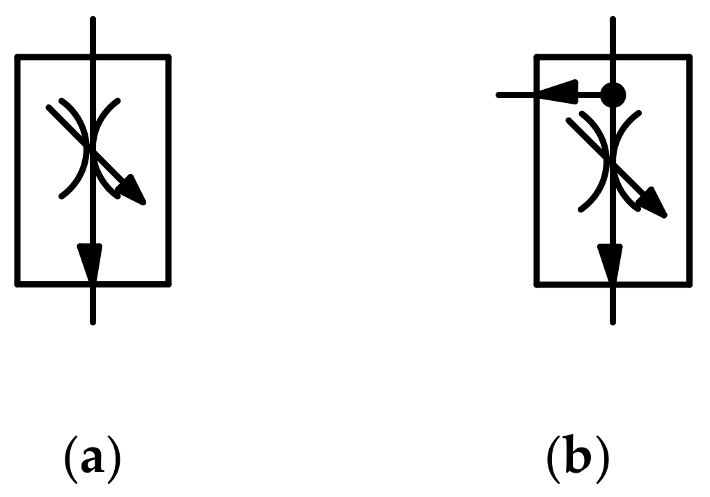
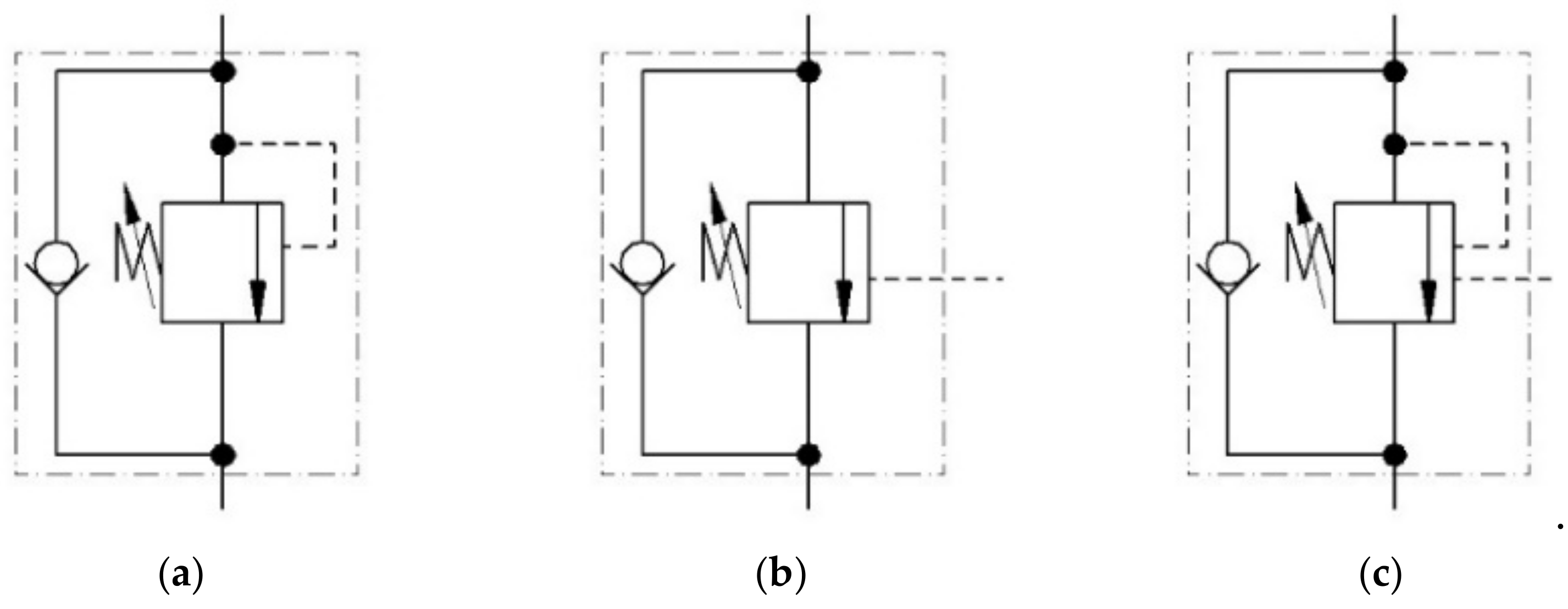
3.3. Braking with a Pressure-Controlled Check Valve

The pilot-operated check valves (pilot-operated non-return valves) differ from conventional check valves in that it is possible to obtain the flow of the working fluid in the opposite direction to the normal direction. The condition for the occurrence of the opposite flow is the appearance of a pressure control signal [5].
For the non-return valve to open, the pressure must reach the so-called opening pressure value of the valve. The valve closes with a delay after the flow has stopped. If adequate, the pressure is maintained in that the valve remains open also for the fluid flowing in the opposite direction to normal [23,24]. For this reason, this valve is only used with double-acting actuators loaded with an active force.
The operation of this type of valve to brake the piston rod is based on the fact that due to the pressure drop in the pump–actuator line, the check valve is closed. In such cases, however, the pump in operation raises the pressure, so before the piston reaches the end of its stroke, it is slowed down and accelerated several times. This causes the loss of smoothness of the piston movement and its uncontrolled motion [25]. To prevent this, a throttle valve in meter-out is used to build up the pressure. The pilot-operated check valve performs best with passive load, preventing unwanted movement of the piston rod when there is no power. It is also used for small, constant active loads (Figure 12). However, it is not a good solution in variable load conditions in one cycle of piston movement [26]. In such systems, very large vibrations and pressure can be induced, which will block the possibility of opening the valve and stop the piston rod.

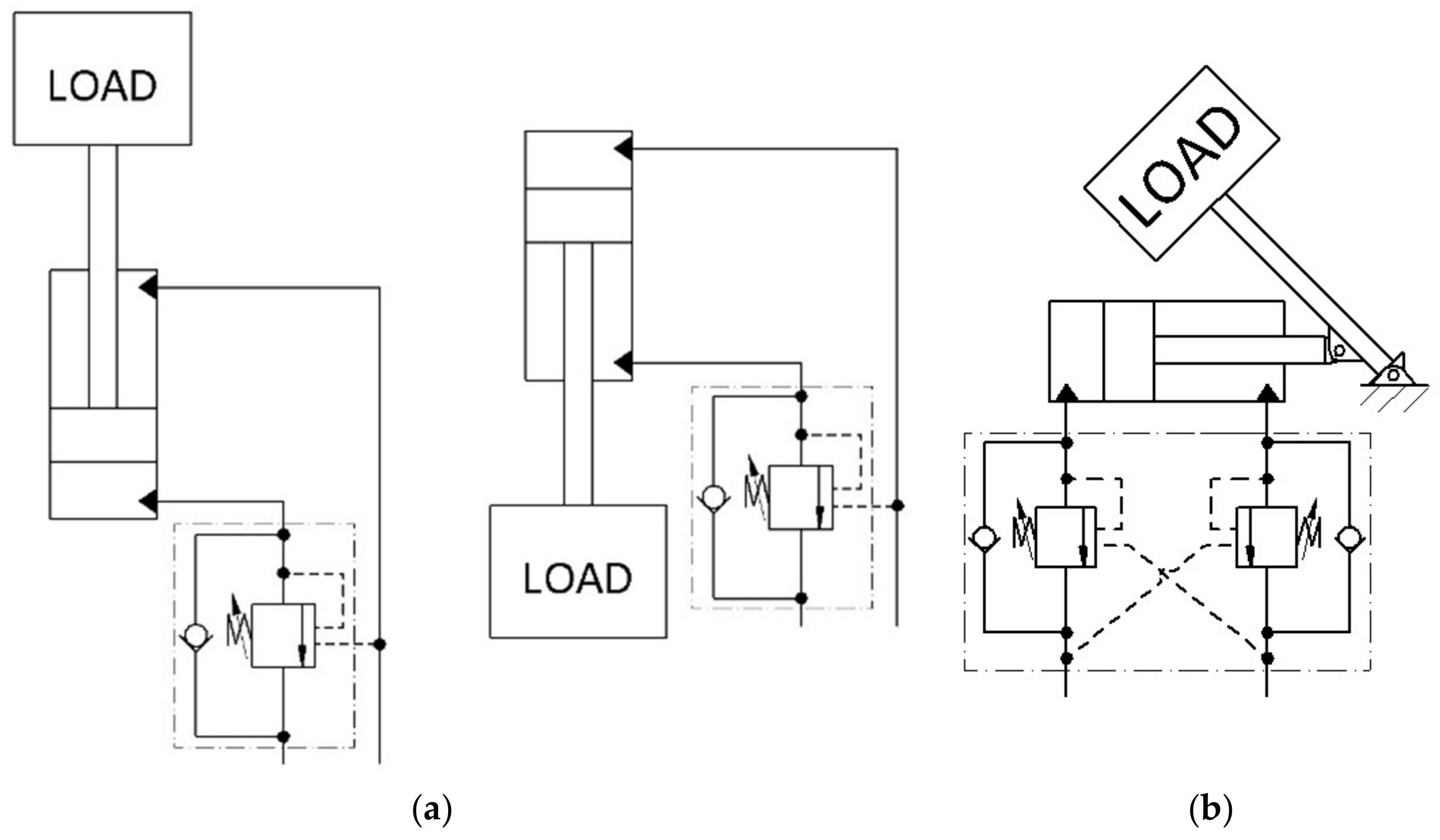
3.4. Braking with a Counterbalance Valve

Braking of the piston can also be performed using counterbalance valves (Figure 13).
The counterbalance valve is a valve whose purpose is to prevent uncontrolled movement of the piston rod in the actuator with any type of loading [27]. Such uncontrolled movements can be dangerous, especially during lowering the load. Counterbalance valves maintain proper pressure, thus providing natural overload protection in the system. In addition, their function is to prevent cavitation, which is particularly important for the durability of the hydraulic system. These valves can regulate the pressure, which may be too small due to low pump displacement and too fast movement of the piston rod [28,29,30,31,32].
The counterbalance valves have the advantage over the pilot-operated check valves that the latter cannot work under overload conditions [26]. The key issue is the selection of the type of the valve itself and the appropriate setting of the flow through the valve. As a rule, the pressure of the working fluid inlet to the cylinder chamber is also the control pressure for the valve in the outlet line [27]. The valve opening pressure must be higher than the load pressure. It is related to the phenomenon of friction of the moving parts of the valve against each other—the re-opening pressure of the valve must be high enough to support the load. Hence, the pressure on the valve is often set about 30% higher than the load pressure [32].
The valves can be internally pilot-operated, externally pilot-operated, or internally/externally pilot-operated. In the case of internally controlled valves (Figure 14a), the valve must be adjusted each time the load changes. It may be troublesome in the case of variable loads [31]. Hence, these valves are only used for permanent loads, as other loads may reduce the performance of the valve. This type of counterbalance valve works like a typical pressure valve. The valve will open when a sufficiently high opening pressure is built up. Therefore, it requires creating additional pressure in the actuator supply chamber. This increases the energy consumption of such a system [32,33]. Externally pilot-operated valves (Figure 14b) do not need to be adjusted for variable loads [31]. Its advantage is that the back pressure is not present when the actuator is in operation (so-called working contact). This occurs as the pressure in the inlet line to the actuator increases and the valve opens. Unfortunately, from the above, there is also a disadvantage: the actuator may stop during the extension movement [33].
Internally and externally pilot-operated valves (Figure 14c) combine the advantages of both above types. Their structure is more complicated. However, it is possible to achieve better control over the operation of the actuator. An important issue in pilot-operated valves is the so-called pilot ratio. It is an indicator of how much the flow setting in the valve decreases with increasing control pressure [27,32]. The selection of the ratio is important, it should be selected to ensure both stability (which is ensured by low ratio) and good efficiency (which is ensured by high ratios) [27]. Such control ensures smooth control of the flow, and thus—of the piston movement. In the event of resistance related to contact with the working element—the valve opens completely. Unfortunately, the valve also requires adjustment, but only with a large load change. Its advantages make it worth using it even for variable loads—even at maximum load, the release pressure is lower than in internally pilot-operated valves [31,32,33].

4. Electronic Control Methods

Recently, there has been a trend to replace hydraulic components with electrohydraulic ones. Mechanical or hydraulic control is increasingly being replaced by electrical control. The flow or pressure control valves are equipped with solenoids. The electric signal causes the valve to open remotely. Thanks to this, it is possible to manage the machine away from it. The signals value sent to the solenoid can be fixed or in range (proportional to the opening orifice inside the valve). This makes it possible to switch the valve to the desired positions or move the spool to an infinite number of positions. By using solenoid directional valves, it is possible to influence the speed of the piston rod and thus its braking. There are two types of solenoid directional valves—proportional and servo.

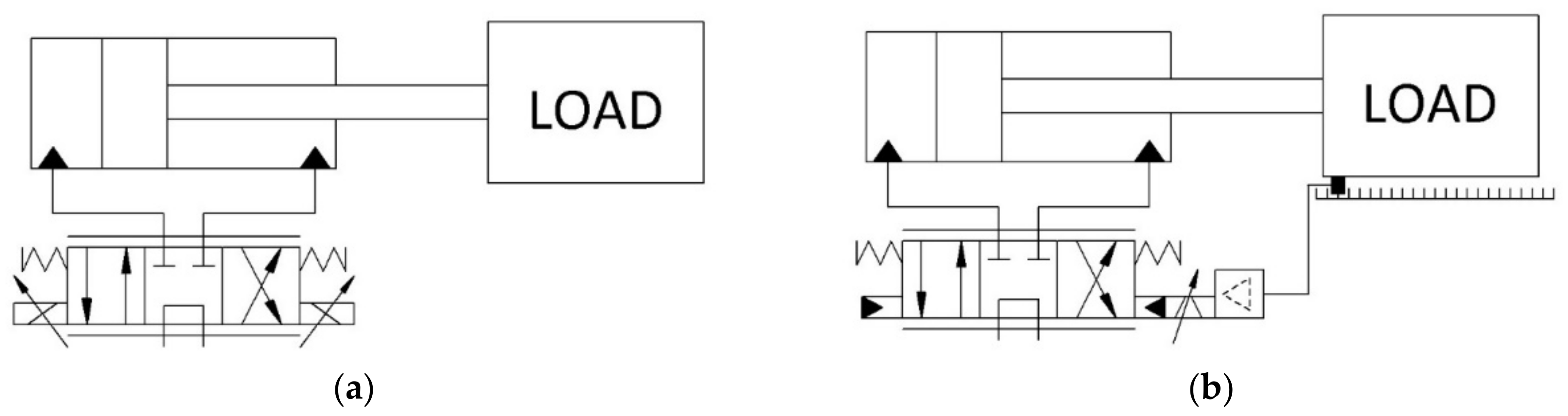
4.1. Braking with a Proportional Valve and Servo Valve

Proportional valves are electronically actuated valves where the output value—pressure or flow—is changed at the same ratio as the input value (current or voltage signal). Control electronics for proportionally designed solenoids are required for actuation. Proportional directional valves are used to control the speed of the piston rods. They can also be used to brake the piston rod at the end of its stroke. The principle of operation is then similar to the deceleration valve shown in Figure 9.
In mobile systems, the use of proportional valves is very popular due to the possibility of smooth control and reducing the energy consumption of the systems [34]. Marusak et al. [35], a predictive force control was proposed for the constrained model of an electrohydraulic actuator. An electrohydraulic actuator with a single-piston rod is used in this study. The control is performed by an analytical Model Predictive Control (MPC) with the constraint handling mechanisms. Satisfaction of output constraints is realized by output prediction. The proposed solution naturally increases the area of application of MPC controllers. Experimental studies presented in this paper have proven that the described controller is characterized by high efficiency. Rigatos et al. [36] deals with the design of nonlinear optimal control of electrohydraulic actuators (so-called H-infinity). In the article, an approximate linearization of the model in the state space was undertaken and then a stabilizing H-infinity feedback controller was designed. This method of control enables fast and accurate tracking of set reference values in the case of moderate changes in the control inputs. Xiao et al. [37], the issue of force control in an electrohydraulic actuator system was addressed. A sliding mode strategy was used. The idea was to divide the system into linear and nonlinear subsystems. A cascaded sliding mode controller is created so that the output of the nonlinear subsystem is forced to track the expected fictitious input data of the linear system, and then the corresponding sliding mode functions are determined for the linear and nonlinear subsystems respectively. The experimental results showed that the system remains stable in a closed-loop, which demonstrates that the effectiveness of such a cascaded sliding force control method for an electrohydraulic actuator is high. Guo et al. [38], the issue of parametric adaptive control of a system with electrohydraulic actuators was presented. In this paper, a model with strict block feedback is described. The developed controller uses a constraint maintenance technique (PPC), which improves the output response and facilitates the expected performance. In Cao et al. [39], the issue of proportional control applied to the control of an electrohydraulic wheel loader is described. To control the working device of the machine accurately, a double-angle sensor was used. In this paper, the proportional control technology was applied to the package implementation of the overhang memory and the automatic levelling of the bucket in the wheel loader. After completion of the experimental verification, a neural network algorithm model was built to minimize the energy loss.
The need for greater accuracy and speed of valve operation resulted in the development of proportional technology and the creation of servo valves. Servo valves are often used in a feedback control where the position or force on a hydraulic actuator is measured and fed back into a controller that varies the signal sent to the servo valve. This allows for more precise movements of the piston rod than the proportional valve. Fung et al. [40] discusses the VSC variable structure control technique applied to an electrohydraulic servo control system. The control system is described by a third-order nonlinear equation with time-varying coefficients. This paper compares the performance of three types of VSC controllers. The experimental results showed that the control system can provide accurate position control, accelerate the output response, and eliminate vibration. Sang et al. [41], an electrohydraulic servo system was used to study bidirectional synchronization iterative learning control (BSILC). The coupling mechanism of two cylinders from two directions was investigated. Experimental results showed that the developed method improved the tracking performance, reliability, and synchronization error compensation.
In Davliakos et al. [42], a six-degree-of-freedom Stewart electrohydraulic platform controlled by an impedance controller is discussed. This controller consists of feedback and an advanced loop that computes the servo valve currents. This loop was designed based on an electrohydraulic model of the system. In the studied solution, the desired motion trajectory is modified by an impedance filter and then sent to the system model. This results in improving the influence of nonlinear hydraulic dynamics on system performance. Experimental results showed that the impedance controller used has better properties than the available PD controllers.
The proportional technique or servo valves can be used in many solutions. Both perform well in controlling the piston rod of every type of actuator under variable load conditions. They ensure full control and safe working conditions of the actuator. The comparison of the proportional valve and servo valve control is shown in Figure 15.

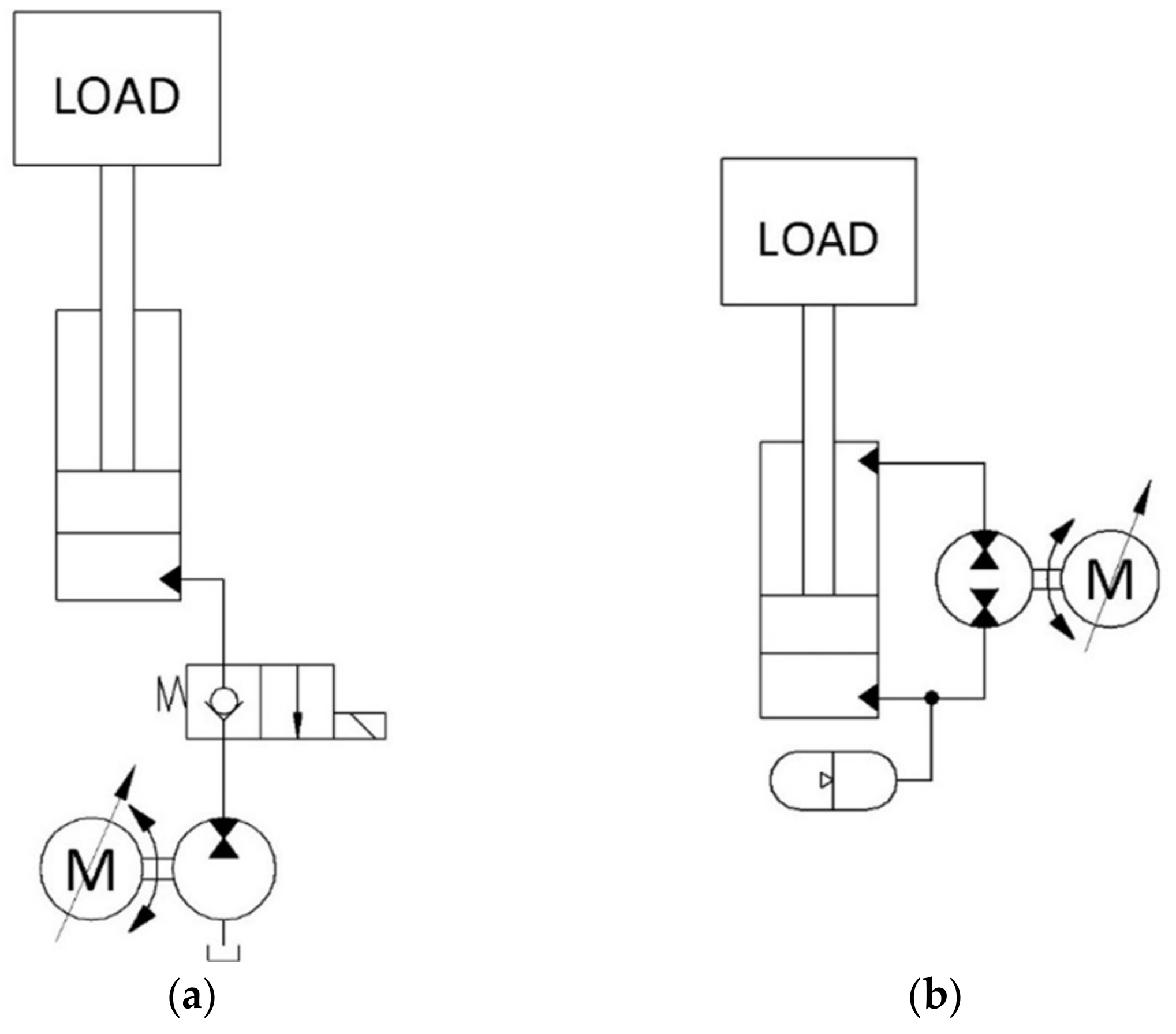
4.2. Braking with a Frequency Inverter

The new trend in reducing energy consumption is electro-hydraulic actuator systems. This has to do with energy-saving requirements [34,43,44]. The use of electrohydraulic elements is justified especially when we have high impact forces and high-power levels [45]. In the context of energy efficiency, electronic control is an important issue. Many authors describe various control solutions to save energy, improve performance, and control accuracy. These systems use the speed control of the electric motor (driving hydraulic pump) based on a frequency inverter. It allows to accelerate and brake the piston rod by appropriately increasing or decreasing the flow rate from the pump. The use of a pump-motor unit and a frequency inverter operating in the vector mode enables the piston rod to be controlled both under passive and active load. Simplified diagrams using the frequency converter in an open and closed circuit are shown in Figure 16. Unfortunately, this solution cannot be used to drive the piston rod with a variable load from passive to active. This would require a change in the direction of rotation of the engine during the movement of the working piston rod. A solution may be the use of two independent pumps and electric motors driven by separate frequency inverters.
Hagen et al. [45] compared the use of electromechanical and electrohydraulic actuators in the motion control system of a single-boom crane. The study showed that the latter solution had 20% more continuous power capacity and 47% less installed electrical power. The authors also cited 79% longer expected life and 33% higher maximum force capability with 25% less weight as advantages of the second solution.
Stawiński et al. [46], authors compare the energy consumption of a scissor lift with two individual propulsions. One is a typical hydraulic system with a throttle valve and the second one is the variable-speed electro-hydraulic system with a fixed displacement pump connected to a motor fed by a frequency inverter. This system was applied to a scissor lift for lowering a hydraulic actuator loaded with an active force. The control process is carried out using an open-loop controller cooperating with a displacement sensor of the actuator. The new solution dispenses with the throttle and distributor, simplifying the hydraulic system. The proposed solution significantly reduces the influence of system geometry, load, and efficiency of system components on the lowering speed of the hydraulic actuator. The discussed control system can maintain the set speed with high accuracy. The modernized drive system can reduce energy consumption by 13%, even though it is a low lifting capacity and low power machine. As an additional advantage of the studied solution, the authors also point out the reduced impact of temperature rise cooperated with systems with a throttle valve.
Systems with the actuator controlled directly by the pump are described by Ketelsen et al. [47]. In this case, it is noted that such a control method allows energy savings of up to 75 % in some applications.
In Padovani et al. [34] and Hagen et al. [48], a study was conducted on a novel electrohydraulic actuator with passive load holding capability applied to a single-boom crane. This actuator was compared with a conventional valve-controlled actuator. By eliminating the control valve, throttling losses were avoided, resulting in energy savings of 62% for the new solution compared to the conventional solution. In addition, a greater gain margin was noted in the new system, allowing for a more aggressive closed-loop position controller. The new circuit also featured improved position tracking capability or reduced rise time. In addition, the new solution has very good sealings, which avoids environmental contamination.
Ahn et al. [49] deals with the design of an electric excavator equipped with six electrohydraulic actuators (EHA). The actuators are quasi-independent in the system studied, so the issue of energy loss and interference is minimized. In conventional hydraulic excavators, the excess energy dissipates as heat. The investigated system allows storing potential energy to recover it later and convert it into electric energy during boom fall. Additionally, it is possible to recover the kinetic energy of the rotating body of the excavator. Simulations showed that the tested cylinders consumed several tens of percent less energy than conventional valve-controlled hydraulic actuators.
Mainly, the direct-drive hydraulic (DDH) systems are studied for energy efficiency. The use of DDH allows for increased efficiency and reduced energy consumption [50,51,52].
Kauranne et al. [43], DDH systems equipped with electrohydraulic actuators were studied. In this paper, they were used for vertical position control, which requires fast movements and the ability to handle large loads. Unfortunately, in such cases, there is a risk of fluctuation. To minimize this phenomenon, the addition of damping was proposed. In addition, the effect of load compensation on the energy efficiency of the system was examined. Conventional DDH, DDH with load compensation, and DDH with load compensation and damping were compared. The results showed that the use of DDH reduced energy consumption by 53% compared to a conventional system with a control valve. The load-compensated DDH was even more energy-efficient (87%), but in this case, vibrations occurred at the end of the machine movement. Adding damping dealt with this, but slightly reduced the energy efficiency (energy consumption reduced by 61% compared to a check valve controlled system).
Heikkinen et al. [50] also a direct drive hydraulic system is discussed. In the review, the authors proposed a direct control of the position and speed of a double-acting actuator. This control is implemented in a closed-loop system without conventional control valves. In this paper, pump/motor displacement compensation and the location of hydraulic accumulators and pump/motor lines with external leakage were investigated. Experimental results showed that the energy efficiency of DDH varies to improve by up to 46% depending on the direction of actuator movement and engine speed.
A variation of the DDH system is the D-DHCD (Digital Direct Hydraulic Cylinder Drive) system. An example of these systems is described by Pedersen et al. [53]. It is direct control of the differential actuator using a single hydraulic pump/motor unit connected to each inlet/outlet of each cylinder. The unit consists of multiple pressure chambers that are independently digitally controlled. This keeps the energy losses to a minimum, as inactive chambers have very low losses. The authors noted that the smooth operation of the system requires digital damping.
In Zhang et al. [54], the concept of a hybrid control strategy for active vibration isolation in a system incorporating electrohydraulic actuators is presented. Single controllers have the disadvantage that a trade-off between performance and durability has to be made. In the case described, there are two controllers. One provides durability in the case of poor knowledge of the plant model, while the other (adaptive) provides high performance. A transfer scheme has been developed to allow more advantageous transitions between the controllers. Experimental results have shown the effectiveness of such a hybrid control strategy.
In Huang et al. [55], the control issue in an electro hydrostatic actuator system used in an aerospace flight control system is presented. The ALS-EHA principle, which is a modification of the EHA principle in the form of a load-sensitive EHA, is discussed. This type of control can adaptively regulate the pump performance in an active way depending on the load pressure. Experimental results have shown that the novel ALS-EHA can reduce motor heating and at the same time reduce the displacement tracking error at speeds close to zero.
In Wang et al. [56], the results of tests on electro hydrostatic reticulation using four-loop cascade control based on the actinic interference compensation method were presented. This method resulted in better durability (by about 35%) and a reduction of static state error (by about 33%).
In Jinxing et al. [57], based on the example of an automated excavator, a parameter identification and control algorithm based on the Hammerstein model was developed. This model was improved to be useful for the time-varying system—modifications including the possibility of adaptive updating of the forgetting coefficient. The results of the tests showed that the presented improvement is most effective in this application.

5. Comparison of Methods of Braking Piston Rods

The methods described in this article have some similarities and can be used interchangeably. The use of an appropriate method is important for several reasons, including safety, positioning accuracy, price, energy consumption and even the possibility of energy recovery or transferring it to other cooperating machines. The methods used to control the speed of movement of the piston rod can be divided into:
  • Actuator type (single or double-acting);
  • Type of load acting on the piston rod (passive, active, variable);
  • Energy consumption and with the possibility of energy recovery.

5.1. Actuator Type Comparison

The methods presented in the article can be used in all types of actuators. The exceptions are the pilot-operated check valve, external and internal/external pilot-operated counterbalance valve. These three valves are not used in single-acting actuators as they require an additional hydraulic control signal. The summary is presented in Table 1.

5.2. Load Conditions Comparison

Depending on the load acting on the piston rod, specific methods of controlling its speed can be used. All of them are suitable in systems where passive force must be overcome. However, it is sometimes energy uneconomical and serves only to reduce the speed of the piston rod in machines operating in intermittent cycles with low load capacities. The possibilities of applying the discussed methods are presented in Table 1. It should be emphasized that all the methods mentioned can be used in combination with others, so that they can work under various load conditions.

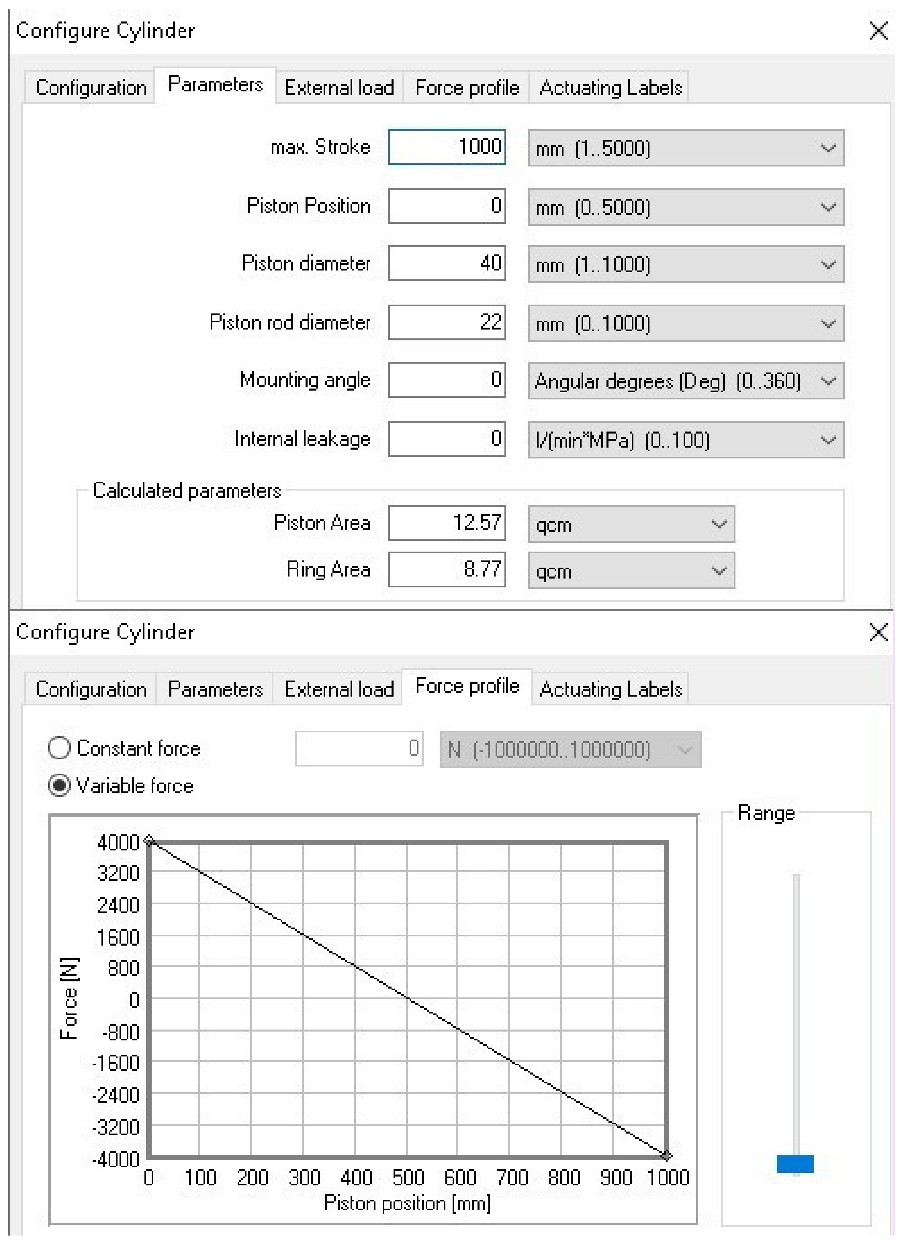
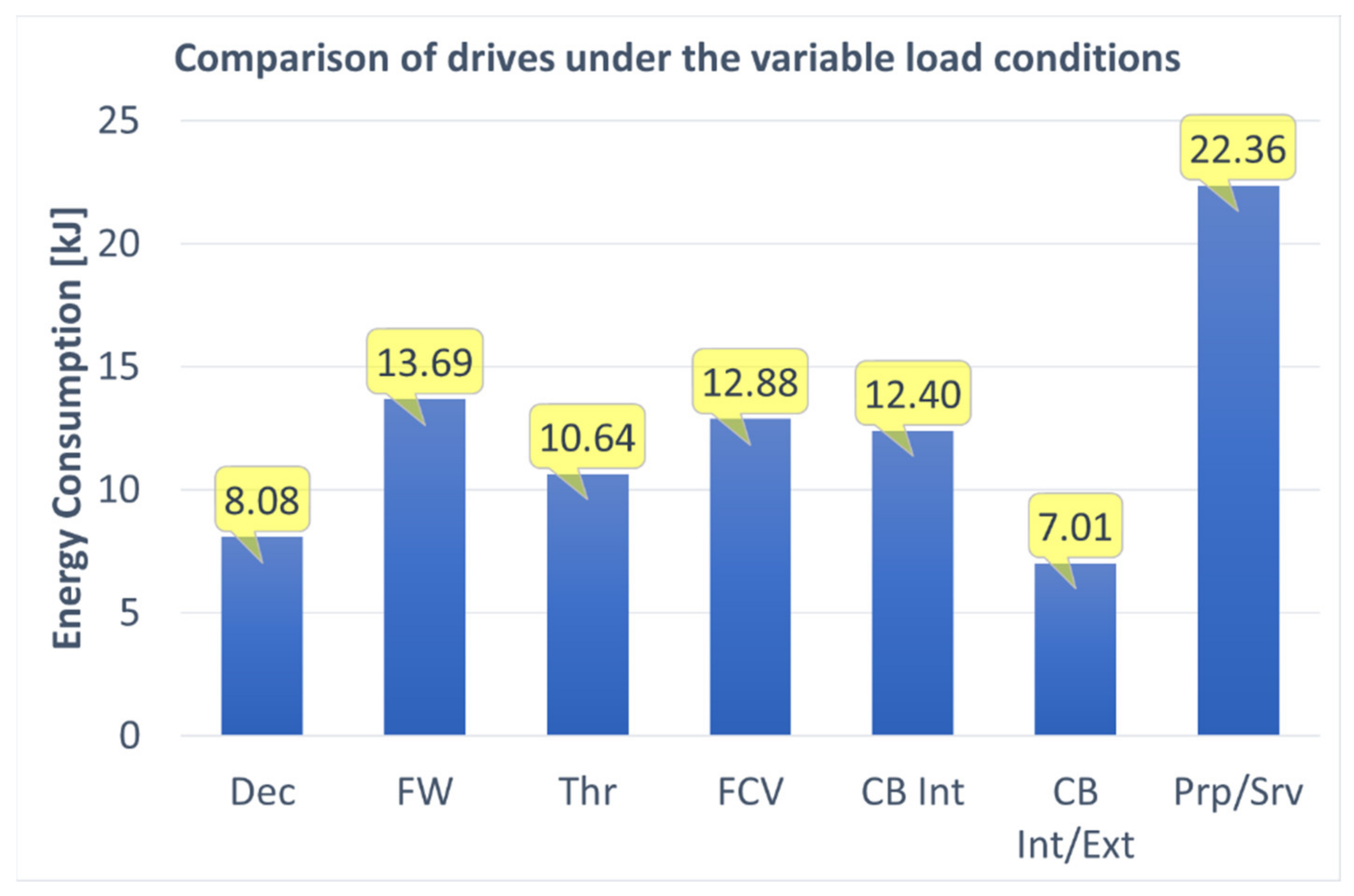
5.3. Energy Consumption Comparison

Due to the wide range of applications, the most interesting seems to be the methods that ensure the safe operation of the machine under variable load on the piston rod. In order to compare the energy demand for these methods, simulation tests of the system with a double-acting actuator loaded with variable force were carried out. The actuator parameters and the force loading the piston rod are shown in Figure 17. The drive unit was a fixed displacement pump. The pump set is shown in Figure 18.
The simulation models were developed in the FluidSim software. The drive remained unchanged with different braking methods. Figure 19 shows the hydraulic diagram of the system with throttle check valves. All the methods used were developed according to the assumptions:
  • No negative pressure in the actuator chambers;
  • Setup of the elements for the lowest possible energy losses;
  • Maximum pressure relief valve setting: 21 MPa;
  • Work cycle consisting of the maximum stroke of the piston rod in both directions with the same time needed to change the direction of the actuator.
The hydraulic power was calculated by measuring the pressure p and the flow rate Q at the pump outlet according to the Formula (4). To estimate the energy consumption, the integration of the power function was conducted according to Formula (5). The study did not consider the additional energy consumption resulting from the supply of control and measurement systems.
P = p     Q
E = 0 t P     dt
The research results are presented in Figure 20. The most energy-efficient method of controlling the speed of the piston rod loaded with variable force is the internally/externally pilot-operated counterbalance valve (CB Int/Ext). Additionally, its advantage is the fact that it does not need an additional power source, e.g., a solenoid coil. The deceleration valve (Dec) is in second place. However, due to the complicated arrangement of the cams, it is not common. The throttle check valve (Thr) seems to be a good solution, taking the third value of energy consumption. It is cheap and can work with any load after proper setting, therefore it is often used in hydrostatic systems. It does not need a power supply, so it does not generate additional electricity losses. Internally pilot-operated counterbalance valve (CB Int), 2-way flow control valve (FCV), and flywheel (FV) methods have similar energy consumption. All three also do not need any additional power supply. The most energy-consuming is the proportional valve or servo valve (Prp/Srv). The main reason is the high hydraulic resistance of such valves. The result is a large pressure loss that must be compensated to overcome the force loading of the piston rod. An additional disadvantage of these valves is the need to supply them with the appropriate voltage generated from a special amplifier.

5.4. Energy Recovery Comparison

Current trends in energy reduction cause the need to look for opportunities to increase the energy efficiency of hydraulic systems. In addition to using the appropriate valves and electro-hydraulic components to reduce the energy consumption, as described above, there is a possibility of energy recovery. It is used in systems with an active load, less often with a variable load. The detailed possibilities of energy recovery have been described in earlier sections of this paper.
Only two methods make it possible to recover energy—a frequency inverter and a flywheel. The use of a frequency inverter in the vector mode during braking of the piston rod loaded with active force requires it to be equipped with an energy recovery module. Currently, special versions of frequency inverters with an integrated module are also produced. Such solutions are used at high loads or in hydrostatic systems that are connected to each other in supply networks, the so-called DC link. It is then possible to transfer energy to each other with less consumption of the power grid.
Even though the flywheel is one of the older methods of storing energy, it is still popular and has a second life thanks to advances in materials engineering and bearings. It enables the reduction of energy consumption and even its recovery in each of the three cases of loading the piston rod. The most common use is a flywheel driven by a hydraulic motor. The energy absorbed by the flywheel powers the generator. The best results are achieved by combining both methods, thanks to which the energy from the flywheel is transferred directly to the common network of the frequency inverter.

6. Conclusions

This article summarizes various methods of controlling the movement of the piston rod in different types of hydraulic actuators under a variable load condition. The possibilities of using methods of safe control of actuator operation and the limitations of their use in specific hydraulic systems are presented.
The review of various methods of controlling the operation of hydraulic cylinders also focuses on the possibilities of reducing the energy consumption of systems of various mobile and stationary machines with AC and DC motors as well as internal combustion engines. Depending on the needs and use, each of the methods is currently used. The analysis shows that the best results under different operating conditions are achieved by the use of a flywheel and a frequency inverter. This requires additional components such as a frequency inverter with an energy return module, a hydraulic motor and a suitable mechanical design for the flywheel. This creates additional costs, but the advantages that can be achieved by combining the two methods are manifold. In addition to the possibility of working with any actuator under any load conditions, we have the possibility of a significant reduction in energy consumption and full control of the piston rod movement. Such solutions can work in automated drives with advanced control systems with significantly reduced energy consumption.
The increasing interest among researchers in such solutions suggests that this is a trend that can bring many benefits for industrial applications in stationary and mobile electrohydraulic systems. This seems to be of particular interest in the era of industry 4.0 and reducing the carbon footprint.
The most difficult task is to select the appropriate method for systems with a variable load on the piston rod during one cycle of its movement. In addition to the safety aspects, an important criterion is the reduction of energy consumption and the very costs of production and maintenance of the hydraulic system. The article summarizes the complexity of the systems and the costs of hydraulic and control components.
On the basis of the simulation model, the study of energy consumption was carried out for a double-acting cylinder under the variable load that varied in one cycle. The simulation results confirmed the analysis of the literature in terms of the advantage of using the counterbalance valve over the others. The worst case is the use of proportional valves, which generate over three times more energy consumption than counterbalance valves.

Author Contributions

Conceptualization, L.S. and A.K.; methodology, L.S.; software, L.S.; validation, L.S. and A.K.; formal analysis, L.S. and A.K.; investigation, L.S. and J.S.; resources, J.S.; data curation, L.S.; writing—original draft preparation, J.S. and L.S.; writing—review and editing, L.S. and A.K.; visualization, L.S.; supervision, A.K.; project administration, L.S.; funding acquisition, L.S. All authors have read and agreed to the published version of the manuscript.

Funding

This research received no external funding.

Institutional Review Board Statement

Not applicable.

Informed Consent Statement

Not applicable.

Data Availability Statement

Not applicable.

Conflicts of Interest

The authors declare no conflict of interest.

References

  1. Osiecki, A. Hydrostatyczny Napęd Maszyn, 2nd ed.; WNT: Warsaw, Poland, 2004. (In Polish) [Google Scholar]
  2. Cylinders. Hydraulics & Pneumatics 2016. Available online: https://www.hydraulicspneumatics.com/technologies/cylinders-actuators/whitepaper/21886842/cylinders-pdf-download (accessed on 25 November 2020).
  3. Menchen, P. Analiza nierównomierności ruchu tłoka siłownika hydraulicznego. Diagnostyka 2005, 33, 277–280. (In Polish) [Google Scholar]
  4. Chałamoński, M. Równomierność ruchu tłoka siłownika hydraulicznego. Diagnostyka 2004, 30, 97–100. (In Polish) [Google Scholar]
  5. Jędrzykiewicz, Z.; Pluta, J.; Stojek, J. Napęd i Sterowanie Hydrauliczne; Akademia Górniczo-Hutnicza im. S. Staszica, Wydział Inżynierii Mechanicznej i Robotyki: Cracow, Poland, 2004. (In Polish) [Google Scholar]
  6. Stryczek, S. Napęd Hydrostatyczny, 4th ed.; WNT: Warsaw, Poland, 2003; Volume 1: Elementy (ang. Elements). (In Polish) [Google Scholar]
  7. Rao, S.N.; Mohamed Sanaullah, A.G. Analysis and design of cushioning in hydraulic cylinders. J. Indian Inst. Sci. 1978, 60, 271–282. [Google Scholar]
  8. Don Norvelle, F. Fluid Power Technology, 1st ed.; West Legal Studies: Eagan, MN, USA, 1994. [Google Scholar]
  9. Tomasiak, E. Napędy i Sterowania Hydrauliczne i Pneumatyczne; Wydawnictwo Politechniki Śląskiej: Gliwice, Poland, 2001. (In Polish) [Google Scholar]
  10. Gordić, D.; Čukić, N.; Jovičič, N.; Šušteršič, V. Mathematical analysis of hydraulic cylinders with cushioning. Tract. Power Mach. 2006, 11, 86–92. [Google Scholar]
  11. Castilla, R.; Alemany, I.; Algar, A.; Gamez-Montero, P.J.; Roquet, P.; Codina, E. Pressure-Drop Coefficients for Cushioning System of Hydraulic Cylinder With Grooved Piston: A Computational Fluid Dynamic Simulation. Energies 2016, 10, 1704. [Google Scholar] [CrossRef] [Green Version]
  12. Arabkoohsar, A. Mechanical Energy Storage Technologies, 1st ed.; Academic Press: Cambridge, MA, USA, 2020. [Google Scholar]
  13. Olabi, A.G.; Wilberforce Awotwe, T.; Abdelkareem, M.; Ramadan, M. Critical Review of Flywheel Energy Storage System. Energies 2021, 14, 2159. [Google Scholar] [CrossRef]
  14. Schmidt, L.; Ketelsen, S.; Brask, M.H.; Mortensen, K.A. A Class of Energy Efficient Self-Contained Electro-Hydraulic Drives with Self-Locking Capability. Energies 2019, 12, 1866. [Google Scholar] [CrossRef] [Green Version]
  15. Li, J.; Zhao, J.; Zhang, X. A Novel Energy Recovery System Integrating Flywheel and Flow Regeneration for a Hydraulic Excavator Boom System. Energies 2020, 13, 315. [Google Scholar] [CrossRef] [Green Version]
  16. Li, J.; Zhao, J. Energy recovery for hybrid hydraulic excavators: Flywheel-based solutions. Autom. Constr. 2021, 125, 103648. [Google Scholar] [CrossRef]
  17. Do, T.C.; Dang, T.D.; Dinh, T.Q.; Ahn, K.K. Developments in energy regeneration technologies for hydraulic excavators: A review. Renew. Sustain. Energy Rev. 2021, 145, 111076. [Google Scholar] [CrossRef]
  18. Tesař, V. Fluid mechanics of needle valve with rounded components, Part I: Configurations and models. Sens. Actuators A Phys. 2017, 254, 101–108. [Google Scholar] [CrossRef]
  19. Khayal, O. Introduction to Hydraulic Systems. In Projects: Hydraulic and Pneumatic Circuits in Heavy Engines, Testing and Analysis of Hydraulic Machinery; Course Name: Mechatronics And Manufacturing Automation; Indian Institute of Technology Guwahati: Assam, India, 2013; Available online: https://nptel.ac.in/courses/112/103/112103174/ (accessed on 20 November 2021).
  20. Beater, P. Pneumatic Drives: System Design, Modelling and Control; Springer: Berlin/Heidelberg, Germany, 2007. [Google Scholar] [CrossRef]
  21. Stryczek, S. Napęd Hydrostatyczny, 4th ed.; WNT: Warsaw, Poland, 2003; Volume 2: Układy (ang. Systems). (In Polish) [Google Scholar]
  22. Totten, G.E.; De Negri, V.J. Handbook of Hydraulic Fluid Technology, 2nd ed.; CRC Press: Boca Raton, FL, USA, 2012. [Google Scholar]
  23. Cundiff, J.S.; Kocher, M.F. Fluid Power Circuits and Control. In Fundamentals and Applications, 2nd ed.; CRC Press: Boca Raton, FL, USA, 2020. [Google Scholar]
  24. Wang, S.; Tomovic, M.; Liu, H. Aircraft Hydraulic Systems. In Aerospace Engineering: Commercial Aircraft Hydraulic Systems; Elsevier: Amsterdam, The Netherlands, 2016; pp. 53–114. [Google Scholar] [CrossRef]
  25. Stawiński, Ł. Układy hydrauliczne do napędu siłowników przy zmiennym kierunku obciążenia tłoczyska. Hydraul. I Pneumatyka 2011, 4, 17–20. (In Polish) [Google Scholar]
  26. Ayers, H. Understanding Counterbalance Valves. Hydraulics & Pneumatics. 2018. Available online: https://www.hydraulicspneumatics.com/technologies/hydraulic-valves/article/21887669/understanding-counterbalance-valves (accessed on 25 November 2021).
  27. Zaehe, B.; Herbert, D. New Energy Saving Counterbalance Valve. SAE Int. J. Commer. Veh. 2015, 8, 583–589. [Google Scholar] [CrossRef]
  28. Yeming, Y.; Zhou, H.; Chen, Y.; Yang, H. Stability Analysis of a Pilot Operated Counterbalance Valve for a Big Flow Rate. In Proceedings of the ASME/BATH 2014 Symposium on Fluid Power and Motion Control, Bath, UK, 10–12 September 2014. [Google Scholar] [CrossRef]
  29. Understanding Pressure-Control Valves. Hydraulics & Pneumatics 2019. Available online: https://www.hydraulicspneumatics.com/technologies/hydraulic-valves/article/21887951/understanding-pressurecontrol-valves (accessed on 25 November 2021).
  30. Stawiński, Ł. Experimental and modeling studies of hydrostatic systems with the counterbalance valves which are used in hydraulic lifting systems with passive and active load. Eksploat. I Niezawodn. Maint. Reliab. 2016, 18, 406–412. [Google Scholar] [CrossRef]
  31. Counterbalance Valve Circuits. Hydraulics & Pneumatics 2008. Available online: https://www.hydraulicspneumatics.com/technologies/other-technologies/article/21883651/book-2-chapter-5-counterbalance-valve-circuits (accessed on 21 November 2021).
  32. Pascal’s Law and Counterbalance Valves: Part 1. Fluid Power Journal. 2019. Available online: https://fluidpowerjournal.com/pascals-law-counterbalance-valves-part-1/ (accessed on 21 November 2020).
  33. Trinkel, B. Sequence Valves and Reducing Valves. Hydraulics & Pneumatics 2007. Available online: https://www.hydraulicspneumatics.com/technologies/other-technologies/article/21884184/chapter-14-sequence-valves-and-reducing-valves (accessed on 20 November 2021).
  34. Padovani, D.; Rundo, M.; Altare, G. The Working Hydraulics of Valve-Controlled Mobile Machines: Classification and Review. J. Dyn. Syst. Meas. Control 2020, 142, 142. [Google Scholar] [CrossRef]
  35. Marusak, P.M.; Kuntanapreeda, S. Constrained model predictive force control of an electrohydraulic actuator. Control Eng. Pract. 2011, 19, 62–73. [Google Scholar] [CrossRef]
  36. Rigatos, G.; Abbaszadeh, M.; Siano, P.; Cuccurullo, G. Nonlinear optimal control of electro-hydraulic actuators. IFAC J. Syst. Control 2021, 15, 100130. [Google Scholar] [CrossRef]
  37. Xiao, L.; Lu, B.; Yu, B.; Ye, Z. Cascaded sliding mode force control for a single-rod electrohydraulic actuator. Neurocomputing 2015, 156, 117–120. [Google Scholar] [CrossRef]
  38. Guo, Q.; Zuo, Z.; Ding, Z. Parametric adaptive control of single-rod electrohydraulic system with block-strict-feedback model. Automatica 2020, 113, 108807. [Google Scholar] [CrossRef]
  39. Cao, B.; Liu, X.; Chen, W.; Tan, P.; Niu, P. Intelligent Operation of Wheel Loader Based on Electrohydraulic Proportional Control. Math. Probl. Eng. 2020, 2020, 1–11. [Google Scholar] [CrossRef]
  40. Fung, R.F.; Yang, R.T. Application of VSC in position control of a nonlinear electrohydraulic servo system. Comput. Struct. 1998, 66, 365–372. [Google Scholar] [CrossRef]
  41. Sang, Y.; Sun, W.; Duan, F.; Zhao, J. Bidirectional synchronization control for an electrohydraulic servo loading system. Mechatronics 2019, 62, 102254. [Google Scholar] [CrossRef]
  42. Davliakos, I.; Papadopoulos, E. Impedance Model-based Control for an Electrohydraulic Stewart Platform. Eur. J. Control 2009, 15, 560–577. [Google Scholar] [CrossRef]
  43. Kauranne, H.; Koitto, T.; Calonius, O.; Minav, T.; Pietola, M. Direct Driven Pump Control of Hydraulic Cylinder for Rapid Vertical Position Control of Heavy Loads: Energy Efficiency Including Effects of Damping and Load Compensation. In Proceedings of the BATH/ASME 2018 Symposium on Fluid Power and Motion Control, Bath, UK, 12–14 September 2018. [Google Scholar] [CrossRef]
  44. Rydberg, K.E. Energy Efficient Hydraulics–System Solutions for Minimizing Losses. In Proceedings of the National Conference on Fluid Power, Linköping University, Linköping, Sweden, 16–17 March 2015. [Google Scholar]
  45. Hagen, D.; Padovani, D.; Choux, M. Guidelines to Select Between Self-Contained Electro-Hydraulic and Electro-Mechanical Cylinders. In Proceedings of the 15th IEEE Conference on Industrial Electronics and Applications, Kristiansand, Norway, 9–13 November 2020. [Google Scholar] [CrossRef]
  46. Stawiński, Ł.; Zaczynski, J.; Morawiec, A.; Skowronska, J.; Kosucki, A. Energy Consumption Structure and Its Improvement of Low-Lifting Capacity Scissor Lift. Energies 2021, 14, 1366. [Google Scholar] [CrossRef]
  47. Ketelsen, S.; Padovani, D.; Andersen, T.; Ebbesen, M.; Schmidt, L. Classification and Review of Pump-Controlled Differential Cylinder Drives. Energies 2019, 12, 1293. [Google Scholar] [CrossRef] [Green Version]
  48. Hagen, D.; Padovani, D.; Choux, M. A Comparison Study of a Novel Self-Contained Electro-Hydraulic Cylinder versus a Conventional Valve-Controlled Actuator—Part 1: Motion Control. Actuators 2019, 8, 79. [Google Scholar] [CrossRef] [Green Version]
  49. Ahn, K.K.; Yoon, J.; Dinh, T. Design and Verification of a New Energy Saving Electric Excavator. In Proceedings of the 28th International Symposium on Automation and Robotics in Construction, Seoul, Korea, 29 June–2 July 2011. [Google Scholar] [CrossRef] [Green Version]
  50. Heikkinen, J.; Minav, T.; Pietola, M. Electric-driven Zonal Hydraulics in Non-Road Mobile Machinery. In New Applications of Electric Drives; Miroslav, C., Ed.; IntechOpen: London, UK, 2015. [Google Scholar] [CrossRef] [Green Version]
  51. Niraula, A.; Zhang, S.; Minav, T.; Pietola, M. Effect of Zonal Hydraulics on Energy Consumption and Boom Structure of a Micro-Excavator. Energies 2018, 11, 2088. [Google Scholar] [CrossRef] [Green Version]
  52. Hagen, D.; Padovani, D.; Choux, M. A Comparison Study of a Novel Self-Contained Electro-Hydraulic Cylinder versus a Conventional Valve-Controlled Actuator—Part 2: Energy Efficiency. Actuators 2019, 8, 78. [Google Scholar] [CrossRef] [Green Version]
  53. Pedersen, N.H.; Johansen, P.; Schmidt, L.; Scheidl, R.; Andersen, T. Control and Performance Analysis of a Digital Direct Hydraulic Cylinder Drive. Int. J. Fluid Power 2020, 295–322. [Google Scholar] [CrossRef]
  54. Zhang, Y.; Alleyne, A.G.; Zheng, D. A hybrid control strategy for active vibration isolation with electrohydraulic actuators. Control Eng. Pract. 2005, 13, 279–289. [Google Scholar] [CrossRef]
  55. Huang, L.; Yu, T.; Jiao, Z.; Li, Y. Active Load-Sensitive Electro-Hydrostatic Actuator for More Electric Aircraft. Appl. Sci. 2020, 10, 6978. [Google Scholar] [CrossRef]
  56. Wang, M.; Wang, Y.; Fu, Y.; Yang, R.; Zhao, J.; Fu, J. Experimental Investigation of an Electro-Hydrostatic Actuator Based on the Novel Active Compensation Method. IEEE Access 2020, 8, 170635–170649. [Google Scholar] [CrossRef]
  57. Jinxing, S.; Hongxin, C.; Ke, F.; Hong, Z.; Huanliang, L. Parameter Identification and Control Algorithm of Electrohydraulic Servo System for Robotic Excavator Based on Improved Hammerstein Model. Math. Probl. Eng. 2020, 2020, 1–9. [Google Scholar] [CrossRef]
Figure 1. Example of a single-acting actuator: (a) spring return; (b) gravity return.
Energies 14 07973 g001
Figure 2. Example of a double-acting actuator: (a) with one-sided piston rod; (b) with a double-sided piston rod.
Energies 14 07973 g002aEnergies 14 07973 g002b
Figure 3. Mathematical models of actuator loads: (a) single-acting actuator; (b) double-acting actuator.
Energies 14 07973 g003
Figure 4. Different load conditions of double-acting actuator: (a) passive load; (b) active load; (c) variable load.
Energies 14 07973 g004
Figure 5. Actuator with a braking gap: (a) working principles; (b) hydraulic symbol.
Energies 14 07973 g005
Figure 6. Scheme of an actuator using the orifice method: (a) working principles; (b) hydraulic symbol.
Energies 14 07973 g006
Figure 7. Scheme of an actuator using the piston groove method.
Energies 14 07973 g007
Figure 8. Flywheel (FW) application.
Energies 14 07973 g008
Figure 9. Deceleration valve (DV) application.
Energies 14 07973 g009
Figure 10. Throttle check valve (Thr) application: (a) meter-out single-acting actuator; (b) meter-in double-acting actuator; (c) meter-out double-acting actuator.
Energies 14 07973 g010
Figure 11. Flow control valves symbols: (a) 2-ways flow control valve (2W FCV); (b) 3-ways flow control valve (3W FCV).
Energies 14 07973 g011
Figure 12. Pilot-operated check valve (POCV) application: (a) active load; (b) passive load.
Energies 14 07973 g012
Figure 13. Counterbalance valve application: (a) active load; (b) variable load.
Energies 14 07973 g013
Figure 14. Counterbalance valve (CB) symbols: (a) internally pilot-operated (CB Int); (b) externally pilot-operated (CB Ext); (c) internally/externally pilot-operated (CB Int//Ext).
Energies 14 07973 g014
Figure 15. Proportional (a) and servo valve (b) applications (Prp/Sev).
Energies 14 07973 g015
Figure 16. Frequency inverter (FI) application: (a) open circuit; (b) closed circuit.
Energies 14 07973 g016
Figure 17. Actuator parameters setup.
Energies 14 07973 g017
Figure 18. Pump unit parameters setup.
Energies 14 07973 g018
Figure 19. An exemplary hydraulic diagram of the system.
Energies 14 07973 g019
Figure 20. Energy consumption of different drives with double-acting actuator under the variable load.
Energies 14 07973 g020
Table 1. Methods used in various types of actuator systems and loads acting on the piston rod.
MethodSingle-ActingDouble-ActingPassive LoadActive LoadVariable Load
CushioningYesYesYesNoNo
DecYesYesYesYesYes
FWYesYesYesYesYes
ThrYesYesYesMeter-OutMeter-Out
2W FCVYesYesYesMeter-OutMeter-Out
3W FCVYesYesYesNoNo
POCVNoYesYesYesNo
CBIntYesYesYesInt or Int/Ext
Prp/SrvYesYesYesYesYes
FIYesYesYesVMNo
Publisher’s Note: MDPI stays neutral with regard to jurisdictional claims in published maps and institutional affiliations.

