1. Introduction
Electrical power systems for space applications are highly demanding in terms of reliability: the related constraints of component screening and Single Point Failure Free (SPFF) circuitry set severe limits on available design solutions. Therefore, specific circuitry and regulation architectures were developed, quite different from those normally in use for stand-alone applications in the terrestrial environment, taking into account the other unique constraints of mass budget, electromagnetic compatibility, and not-convective heat exchange.
In addition, even the operating environment is quite different from terrestrial applications [
1]. Spacecraft are exposed to a severe radiative environment that affects both solar cells, via crystallographic damage mainly related to absorption of energetic particles, and electronic components, that are also affected by the secondary radiation generated as a byproduct of the interaction between cosmic rays and spacecraft materials. Sunlight is also different as, unfiltered by the atmosphere, it is richer in photons in the visible and ultraviolet (UV) range, up to the UV-B spectral region (AM0 spectrum). Solar irradiance is 1367 W/m
2, with ±3.5% seasonal variations for eccentricity of the Earth’s orbit around Sun, plus some minor random fluctuations related to solar activity. Spacecraft periodically undergo eclipses with characteristics dependent on orbit geometry: in the most common Earth orbits the time spent in darkness ranges between 30 and 70 min, and sunlight time between successive eclipses varies from 1 h to some months.
The average albedo for Earth orbits is commonly assumed to be around 30%: in reality, it varies over the sunlight time, reaching its maximum when a spacecraft flies over the icy and cloudy poles, and its minimum over the “dark” oceans.
Solar panels in a common configuration are arranged as wings, continuously rotating around their axis to ensure normal incidence of direct solar radiation. Continuity of the current paths is achieved by dedicated slip rings inside the Solar Array Drive Mechanism (SADM). Many satellites otherwise have solar cells integrated in the external surfaces of the spacecraft body. In this case, the tilt angle of solar cells may be not uniform, leading to a diminished use of their photovoltaic surfaces. On the other hand, body-mounted solar arrays benefit from reduced complexity (no SADM or slip rings are needed) and are characterized by a smaller moment of inertia, enabling a more agile attitude control of the spacecraft.
The actual solar cell temperature depends on the details of the solar panels and the specific orbit: in the case of body-mounted solar cells, their good thermal conduction keeps solar cell temperature within a few degrees with respect to the satellite body, which is typically around 0 °C, whereas in the case of solar panels arranged as solar wings the deviations can increase to several tens of degrees, due to the ineffective heat exchange with the satellite body and to the higher relevance of radiative heat exchange to the dark space and to the Earth’s surface. The orbit’s altitude also affects temperature via the Earth’s field of view: the minimum temperatures decrease to ≈−150 °C passing from LEO orbits (300–1000 km altitude) to Geostationary orbits (35,786 km altitude), whereas the maximum temperatures typically vary in the range +40 °C to +80 °C. In solar wings, the operating temperature also depends on the back-surface finish of the panels. Due to the small rate of heat exchange and to the high solar cell efficiency (typically in the 28–31% range), when a solar panel is in MPPT (Maximum Power Point Tracking) the heat to be dissipated is more than 400 W/m2 smaller than that observed in the open-circuit conditions, with a temperature drop that can reach a few tens of degrees.
Temperature transition rate also is a peculiar stress source for space solar arrays: in near-Earth orbits, at the end of eclipses (from eighty to six thousand times a year), the temperature of solar cells in a few minutes rises from a deeply negative value (−30/−150 °C, depending on the orbit altitude and on the satellite layout) to a positive value (+40 °C to +80 °C, depending on the layout of solar panels and the electrical operating point).
Mismatching is also an issue in space solar arrays. Controlled-pointing solar panels are not always used in spacecraft as sometimes the more compact approach of body-mounted solar cells is preferred. If this is the case, the different tilt angles affect the current–voltage characteristics of the single photovoltaic strings. Even in the most common case of controlled-pointing solar panels, several sources of mismatching can modify the current–voltage characteristics of a photovoltaic (PV) string in unpredictable ways. Among them, worth mentioning are temperature gradients, arising whenever the spacecraft enters eclipse. Other sources of mismatching may be partial shading, statistical dispersion of technological parameters, and solar cell failures. All of them can affect solar array uniformity by modifying the current–voltage characteristics of a string in unpredictable ways.
Since the 1970s the most widely used approach for spacecraft power conditioning has been Sequential Switching Shunt Regulation (S
3R) [
2], because of its high power density, modularity, simplicity, and inherently high reliability. Such shunt regulators also provide high power-path efficiency [
3,
4], as a solar array is split into sections that can be either directly connected-to or disconnected-from the power bus, as happens in the other regulation schemes belonging to the wider family of Direct Energy Transfer (DET) regulators: the Sequential Switching Shunt Series Regulator (S
4R) [
5], the Astrobus™ [
6], the shunt module developed for the Galileo Power Conversion and Distribution Unit (PCDU) [
7], and the Sequential Switching Shunt Maximum Power Point Regulator (S3MPPR) [
8].
Power regulation schemes implementing Maximum Power Point Tracking (MPPT) techniques have been introduced since the 1990s [
9,
10]. At the expense of a larger complexity [
11,
12], they provide optimal energy harvesting in a wide range of operating conditions. This is critical in missions in Deep Space, such as Rosetta-Mars Express [
11,
13] or GOCE [
14], and in certain low Earth orbits, where the solar array characteristics undergo wide variations for temperature, intensity of solar radiation, or aging. The typical MPPT Solar Array Regulators are based on classical Pulse Width Modulated (PWM) series switching converters [
15]. The converter is a stepdown in most applications, such as Globalstar 1 [
9], Mars Express, Rosetta [
11], Venus Express [
16], Goce [
14], Swarm [
17], Lisa Pathfinder [
18], Juice, and Exomars [
19]. In most cases, the configuration is the two-inductors buck configuration [
20]. Step-up configurations were used for Globalstar 2 and some high-power spacecraft such as BepiColombo [
13,
21]. Top flexibility in the solar array configuration is achieved by using Solar Array Power Regulators (APR) comprising step-up/step-down converters [
22,
23], so that the solar array voltage may vary across the power bus voltage.
A first attempt to gather advantages of both approaches by introducing MPPT capability in S
3R power units was proposed in [
24]. It was further developed in [
8,
25] and then specialized for applications in spacecraft with electrical propulsion [
26] or in geostationary satellites [
27].
All previously introduced regulation approaches provide specific advantages and limitations so their trade-off has been widely debated [
15,
27]; so far, no power conditioning technique has been established as a standard. The heritage of manufacturers and agencies also affects the trade-off.
This work is intended to contribute to the debate taking into account in the trade-offs of other specific solar array management techniques capable of providing advantages with respect to all previously reported approaches.
In sectional MPPT power units [
15], the solar array is split into several sections, each fitted up with a dedicated Solar Array Power Regulator (APR) with a multimode controller, capable of either independently performing MPPT or harmonically contributing to the regulation of the bus voltage or the battery current. Coordinate operation of the different APR in regulation mode is a major issue with these systems so some authors [
28] developed to the purpose algorithms to be embedded in powerful supervisors.
An expedient solution appears to be provided by the Sequential Maximum Power Tracking (SMPT) bus regulation technique: the coordination problem is solved by implementing an operational sequence such that just one section at a time is kept in control mode, while the others are kept either in MPPT or in standby.
A thorough description of the main regulation techniques and SMPT operation is given in
Section 2. A comparative analysis of S
3R and the regulators based on MPPT or SMPT techniques is discussed in
Section 3 with reference to a typical space mission in low Earth orbit, in the presence of relevant mismatching in the solar array.
Section 4 is dedicated to the demonstration of SMPT operation, based on both a Matlab–Simulink model and on the experimental results provided by a breadboard built with automotive-grade components.
2. Solar Array Regulation Approaches
2.1. Sequential Switching Shunt Regulation
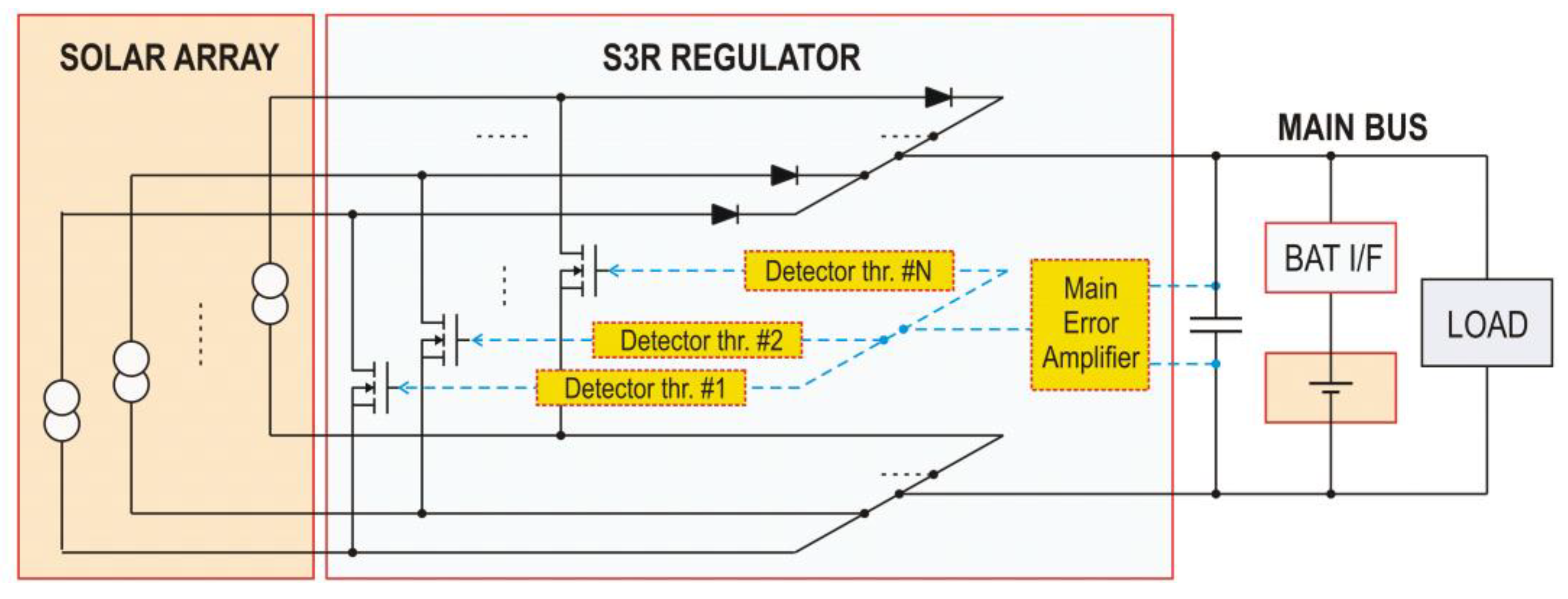
In S
3R systems, the solar array is split into N sections directly connected to a power bus via blocking rectifiers. Each of them is also equipped with a shunt switch that can be tripped on in order to block power transfer to the bus (
Figure 1). In order to reach a power balance between solar array generation and load absorption, the active solar array sections are set according to a pre-ordered sequence [
4]: when the required solar array generation G
SA is smaller than the power supplied by M solar array sections, but larger than the power supplied by M − 1 of them, rough regulation is provided by keeping M − 1 sections permanently enabled and the other N-(M − 1) permanently disabled. Fine regulation is achieved by hysteretic control of the duty cycle on the shunt switch of a single solar array section.
The battery is typically interfaced to the bus via a Battery Charge Regulator (BCR) and a Battery Discharge Regulator (BDR) (full-regulated bus configuration). The BDR may be replaced by a simple rectifier (sun-regulated bus), especially in the missions involving a small Depth of Discharge (DoD).
Regulation control is performed by a Main Error Amplifier, generating both the activation sequence for the direct-current (dc) shunts and the duty cycle for the switching solar array section. It is based on a consolidated, simple, and Single Point Failure Free (SPPF) circuitry, with very high reliability.
A variant DET regulation scheme, the Sequential Switching Shunt Series Regulation (S
4R) has also been proposed, with an original configuration of the battery charge regulator [
29] that is more efficient and decoupled from the bus regulation control. The improvement comes with a reliability issue, as in the original layout the battery-charging path is not SPFF [
30].
For the sake of the analyses proposed in this work, minor differences in performance are observed among Direct Energy Transfer (DET) regulation approaches and thus only S3R will be considered.
2.2. Maximum Power Point Tracking Regulation
The photovoltaic source supplies the power bus via a series dc–dc converter enslaved to a multimode controller that can operate in either regulation or maximum power point tracking (MPPT) modes.
A survey of Maximum Power Point Tracking techniques is given in [
31], whereas deeper insight about modelling and stability issues can be found in [
32] and [
15,
33], respectively. The same algorithms used in stand-alone terrestrial applications may be used: Perturb and Observe [
34] is preferred when the MPPT controller is embedded in software, whereas Incremental Conductance can be implemented by a hardware circuit, as described in [
11]. The first one is more flexible and can be easily upgraded to manage quick transients or multiple maximum power points. On the other hand, some kind of digital processor is required, which can be quite expensive when carried out with space-qualified devices. The latter only requires a few discrete components but can face some stability problems in managing fast load variations [
12]. The main difference with the MPPT algorithms for terrestrial applications is in the dynamical model of solar panels, which are made with solar cells based on technologies not used in terrestrial applications.
When load absorption is small, the multimode controller is in either constant-current or constant-voltage regulation mode and the operating point of the solar array typically is in the low-current region. Thus, in response to an increase of power absorption from the loads, the feedback loop increases the duty cycle, pushing the SA operating point towards higher currents [
34]. When current exceeds the Maximum Power Point, further increases of duty cycle result in power reductions, and the controller switches to the MPPT mode. From there, the operating point is driven to and kept close to the global maximum power point, according to a proper tracking technique. The regulation mode starts again when the load absorption returns below the maximum available power from the solar array.
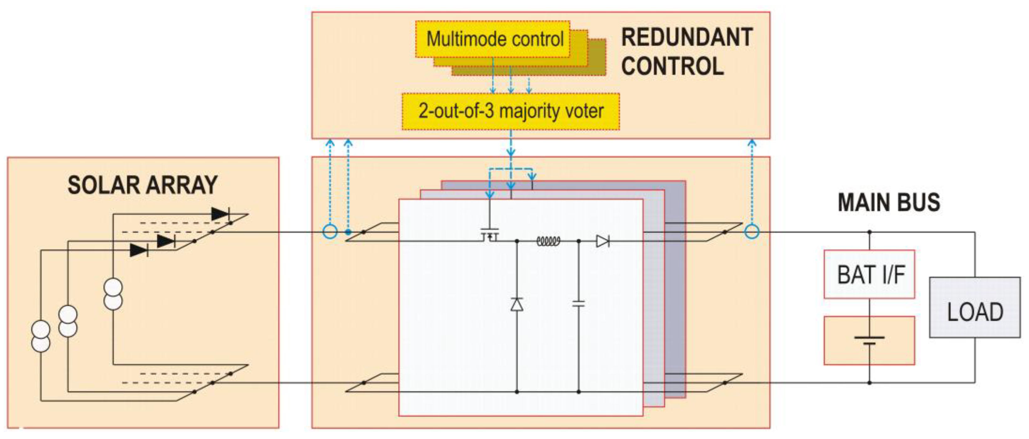
On the other hand, the system architectures are heavily affected by the requirements of reliability: several redundancies are normally introduced in the power conversion unit in order to avoid the risk of Single Point Failures. In the configuration used for many space missions [
11,
16], the whole solar array is split into two parts, corresponding to the spacecraft wings. In each of them (
Figure 2), all photovoltaic strings are connected in parallel to supply a power module comprising three hot-redundant converters. Precisely the redundancy scheme is two-out-of-three partial redundancy [
11] because each converter is sized to carry up to 50% of the overall power so that losing one of them will not affect spacecraft operation. In the space power literature, this configuration for the solar array regulator is commonly referred to as “MPPT”.
The controller also consists of three modules connected according to the majority voting redundancy scheme, allowing for the detection and dismissal of a single unmatched signal. The output bus is regulated, involving the use of both battery interface converters, with their mass and power losses.
2.3. Comparing MPPT and S3R
The trade-off between MPPT and S
3R has been widely debated in the space power community [
4,
11], as both provide specific advantages. This led to several proposals to combine the specific advantages of both techniques [
23,
24], also developing techniques tailored for specific applications [
26,
27].
The S3R controller is based on a consolidated circuitry, simple and SPFF, that easily matches the required levels of reliability.
The MPPT-SAR scheme reported in
Figure 2 involves more complex circuitry, and reliability has to be increased by the redundant connection of parallel converters. In practice, in addition to using reliable and SPFF circuitry inside the different converter blocks for their coordination, it is necessary to make them functionally independent, preventing propagation of any type of failure along any power or signal lines, and also avoiding harmful thermal couplings.
The shunt regulation approach used in S3R minimizes dc losses in the power path, as just the blocking rectifiers are in series to the electrical connections. The switching losses also are small, because alternate current (ac) flows only in the section performing fine regulation, and the ac losses are substantially limited to charging/discharging of the switch capacitances, at a frequency that is typically in the 10–20 kHz range. The ripple is filtered out by a capacitor bank with no inductors. Thus, efficiency can be larger than 96%, depending on the bus voltage.
In reality, the serial dc–dc conversion used in MPPT regulators involves larger power losses [
35], as the whole current undergoes switching at a frequency of a few hundreds of kHz [
11], generating appreciable ac power losses both in the active devices and in the magnetic components. In space missions with few eclipses and stable operating conditions for the solar arrays, e.g., geostationary satellites, the related losses (typically a few per cent) can offset the benefits of the Maximum Power Point Tracking capability, and DET converters are preferred.
On the other hand, energy harvesting in S3R is less effective, because the solar array has the voltage tied to the bus voltage, independent of its actual current–voltage characteristics. Thus, wide margins must be taken in the solar array design in order to avoid that—in the most unfavorable conditions—parametric variations (e.g., due to heating or aging) may cause the Open Circuit Voltage of any string to fall below the bus voltage. This causes inefficient use of the solar panels, which normally are operating at voltages far from their maximum power point voltage (VMP) even during the load peaks.
Otherwise, in the case of MPPT, especially when a converter configuration with buck-boost capabilities is chosen [
22,
23], all available power can be exploited independently of solar array voltage. This capability may be used for more effective sizing of solar arrays, and/or to produce extra power. It could simply be used to reduce the depth of the battery cycles, allowing for smaller batteries, with advantages also from a systems point of view. In some missions the extra available power can be used to increase, even temporarily, payload capability (e.g., in a TLC spacecraft to increase the number of transmission channels) and/or to widen the payload duty cycle.
In MPPT-APR the bus voltage is decoupled from solar array voltage, thus enabling the direct connection of the battery to the bus (unregulated bus configurations), at least in the missions involving small battery Depth of Discharge. Therefore, the mass and the power losses of both BCR and BDR may be avoided, even if they are still used in specific spacecraft, e.g., in [
11].
The challenge of merging MPPT functionality into S
3R systems with no reduction in reliability and a negligible increase in complexity was first faced in [
24]. The proposed approach was to enslave the bus voltage in S
3R to an MPP tracker [
4]. This can be done by minimal modifications to the classical S
3R circuitry and has a main drawback, related to the wide variations of the bus voltage (tens of volts) arising from V
MP variations. Such variations can be managed either by widening the input range for all devices connected to the bus, at the expense of their performance, or by introducing some bound to the voltage tracking range, at the expense of the energy harvesting capability. In either case, using a full battery interface is mandatory, with the related mass and power losses.
In the systems based on the MPPT-SAR in
Figure 2, as in S
3R, all photovoltaic strings are connected in parallel so that any source of mismatching would make the overall maximum power smaller than the sum of the maximum contributions that would be available from individual strings. Therefore, both approaches appear to be not perfectly fitted for missions in low Earth orbit, where eclipses frequently trigger temperature transitions, with the related thermal gradients inside the solar array, and sometimes partial shading.
2.4. Sequential Maximum Power Tracking Regulation
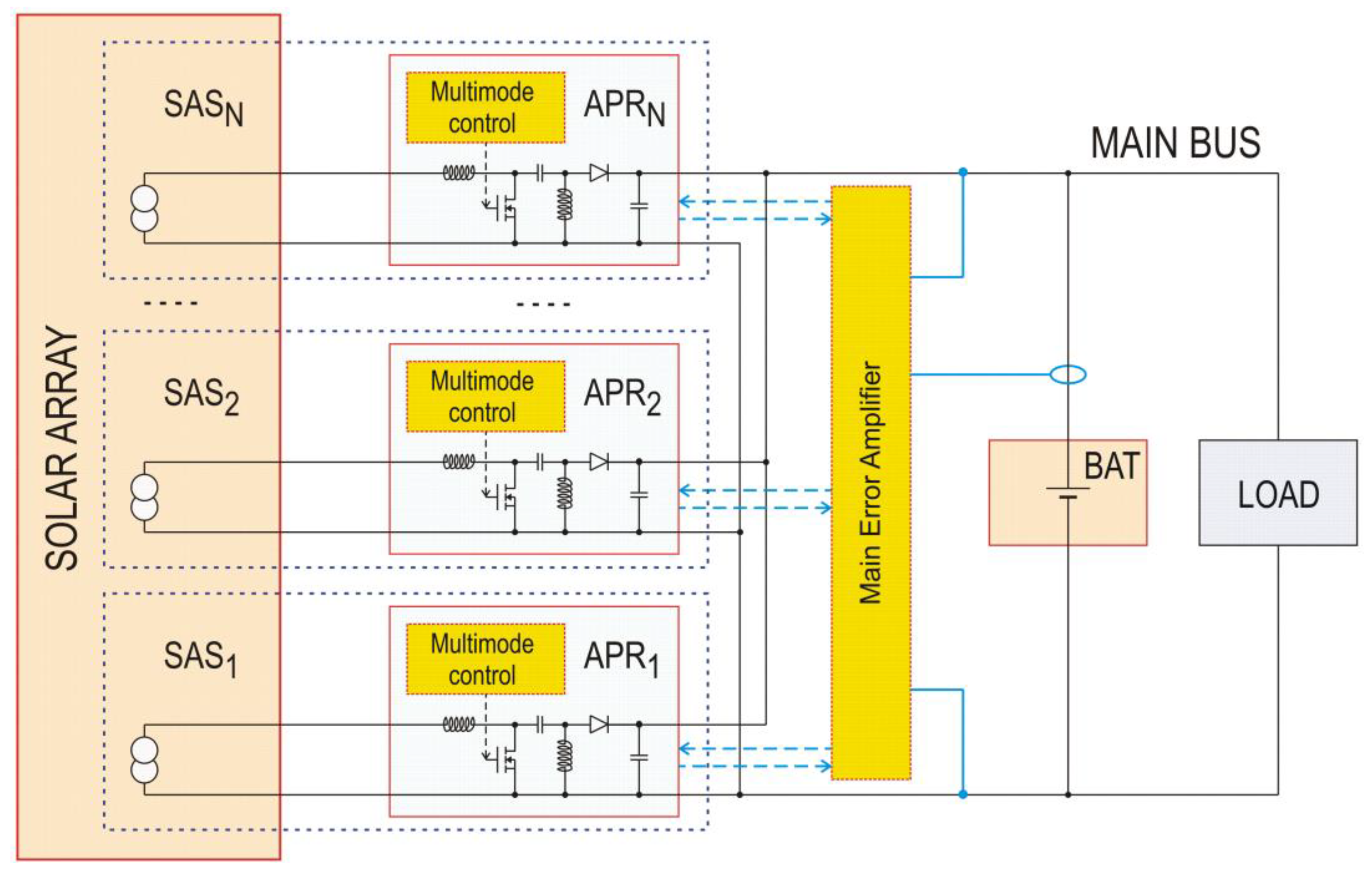
The effects of mismatching are reduced with the sectional MPPT configurations [
15], first used in [
9]: the solar array is split into N sections independently interfaced to the power bus by means of dedicated APRs (
Figure 3) capable of tracking their individual MPP to provide optimal energy harvesting. This feature appears particularly interesting in spacecraft with body-mounted solar cells, where the variable angles of incidence may force photovoltaic strings to work at different operating points. Sectional MPPT may also reduce the effects of other sources of mismatching, such as temperature gradients, partial shading, statistical dispersion of technological parameters, and solar cell failures. All of them can affect solar array uniformity by modifying the current–voltage characteristics of any string in unpredictable ways.
Despite these advantages, and all other advantages of MPPT–SAR that still are effectual, sectional MPPT has seldom been used in space. An issue for its application with battery buses is the need to coordinate the different APRs during the regulation modes through effective and reliable circuitry. SMPT provides an effective solution to this issue.
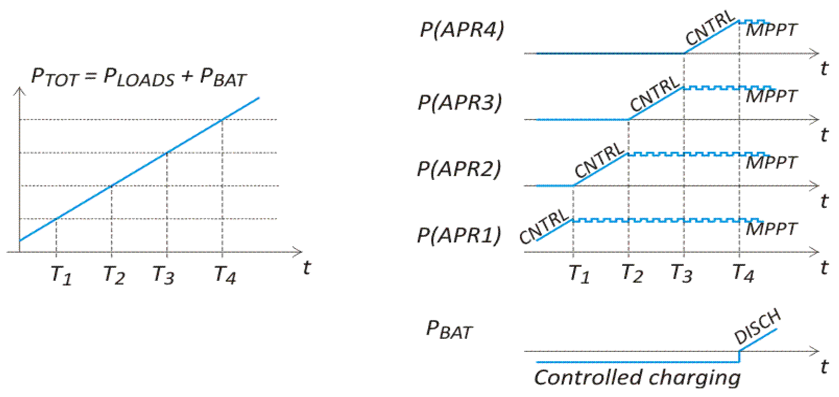
Each APR can either autonomously perform current/voltage regulation based on shared feedback signals or can manage MPPT for the dedicated solar array section. At the same time, all APRs share their operational status via redundant I/O lines. Thus, the SMPT algorithm is implemented on the basis of both shared status signals and of shared feedback signals. The issue of coordinating the operation of the APRs is faced by keeping just one of them in regulation mode, with the others either in MPPT or in standby. The power-up sequence outlined in
Figure 4 clarifies SMPT operation: at turn-on an APR starts operating in regulation mode, autonomously adjusting its output power to enforce the desired control law. If the feedback loop drives it in MPPT, the next APR in the sequence is turned on and takes charge of regulation. The sequence continues until the desired bus condition is achieved, e.g., with APR
M in regulation mode, APR
1 to APR
M−1 in MPPT mode, and APR
M+1 to APR
N in standby. In response to a decrease of the load absorption, the sequence is run in the opposite direction: when the feedback loop is going to quench APR
M, APR
M−1 exits MPPT mode to start regulation, while APR
M ends in standby.
Thus, the operational state of all APR’s is coordinated based on a small number of signals, that can be easily made SPFF.
An option for the sequence control is to use a central device, in charge of exchanging status signals and enabling signals with all APRs. The control circuitry as well as all I/O lines must be redundant and Single Point Failure Free, to avoid that a single malfunction may result in a failure for the entire power system.
In the case of low-cost missions based on Components Off The Shelf (COTS), the reliability of single components is not easily predictable, and the two-out-of-three redundancy scheme may not be sufficient to ensure required reliable operation. Thus, it could be convenient to use a distributed sequence control, where each APR autonomously manages its operational mode according to the shared status signals and a wired sequence. In order to avoid that the loss of control on a single APR may affect the target performance, it is easy to use the SMPT modularity to implement partial redundancy schemes, such as N-of-(N + 1), so that the need for a Failure Free central control unit is offset to the requirement of no-failure-propagating interfaces (signal, power and thermal) among different APRs.
In any case, SMPT also is intrinsically more reliable than the classical parallel MPPT, first because there is no input node with all PV strings connected in parallel. Moreover, the last APRs in the sequence can spend most of their time on standby and therefore undergo a reduced failure rate [
36].
When SMPT regulation is compared to S3R, all advantages of sectional MPPT are confirmed: it allows high flexibility in designing solar array voltage and can use MPPT to get top power harvesting even in mismatched solar arrays. It also shares some drawbacks, related to the larger complexity of the switching cells, even if this is partially compensated by the possibility of using an unregulated bus, thus avoiding the burden of the battery interface converters.
A summary of the main features of the investigated regulation techniques is provided in
Table 1. The first row reports the efficiency of the conversion cell, as it represents the top efficiency theoretically reachable by the converter when neglecting all the power used to supply controllers, telemetries, redundancies, and all service circuitry. For instance, in the case of the two-out-of-three partially redundant systems reported in [
11], three dc–dc converter cells are continuously running at a power level that is not exceeding 66%, until a failure event blocks one of the converter cells. Thus, the efficiency of the overall regulator is reduced due to a non-optimal power level and is also affected by the triple control circuits, so that it can hardly be evaluated, despite the fact that losses in the conversion cell are easily predicted.
3. Comparison among the Regulation Techniques
A trade-off analysis of the considered regulation techniques has been developed. The analyses are in reference to a specific case study, an Earth Observation Spacecraft flying in a Sun-synchronous orbit at 380 km altitude, characterized by [
1], an orbital period T0 = 90 min, with 30 min eclipse duration. This trend is typical for low Earth orbits: the exact value of the irradiance duty cycle depends on orbital altitude, inclination, and eccentricity, and in a circular orbit it is lightly larger than 66% at 300 km, and smaller than 60% at 1500 km. Only in very special orbits it can be close to 100% (e.g., in down-dusk orbits, where the orbital plane is almost orthogonal to the solar vector). Due to this variability, we were forced to develop our analyses in reference to a very specific space mission, assuming that the general conclusions could be extended to similar applications, including many low Earth orbits with pulsed loads.
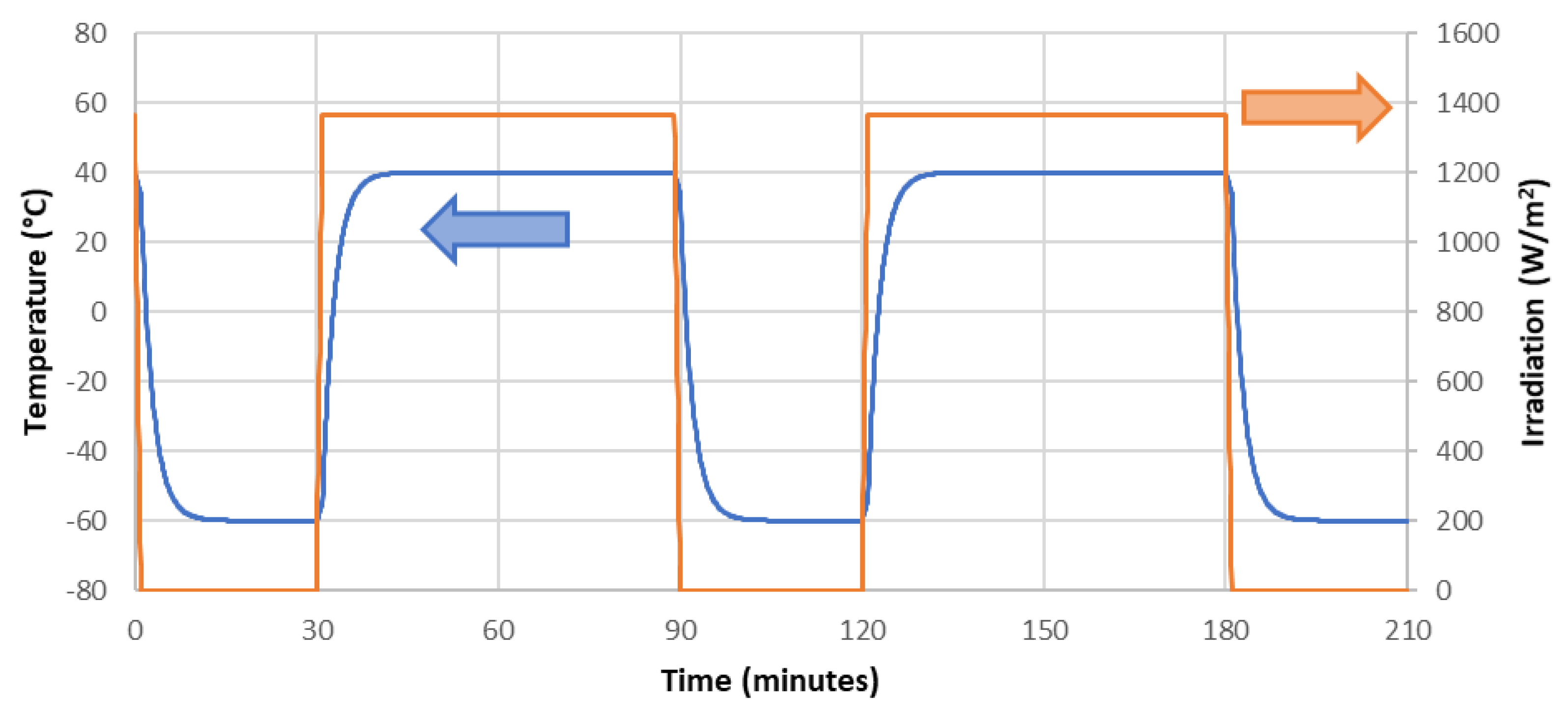
In order to perform a straight trade-off analysis, the solar radiation collected by the panels has been assumed to be only affected by eclipses (step transitions from darkness to sunlight, neglecting penumbra times) and by solar panel temperature. As the actual solar cell temperature depends on the details of the solar panels, in our analyses we referred to typical textbook data for low Earth orbit missions [
37] (Sections 9.3–4) and assumed that temperature was in the range −60 °C (at the end of eclipse) to +40 °C (at the beginning of eclipse).
Figure 5 reports the trends considered for this trade-off analysis for irradiation (orange curve, right axis) and temperature (blue curve, left axis).
The solar array considered for this case study was able to provide 1.4 kW in AM0 at Beginning of Life and consisted of 1088 triple-junction solar cells, model CTJ30 by CESI, arranged in 64 strings of 17 series-connected cells, grouped as 8 independent sections. The analyses were based on their expected performance after aging by absorption of a radiation fluence of 5 × 10¹⁴ equivalent 1 MeV electrons, corresponding to several years in a typical Sun-synchronous polar orbit.
In order to stress differences among the regulation approaches investigated in this work, mismatching among solar array sections has been taken into account. In particular, it was assumed that a section underwent a relevant reduction of the output voltage, which in real operation may be caused by damaging or shadowing a group of solar cells, with activation of the dedicated bypass diodes.
Table 2 collects the values of Open Circuit Voltage (V
OC), Short Circuit Current (I
SC) and their thermal coefficients considered for the different solar array sections.
The model for Solar Arrays accounts for temperature effects on the solar cell characteristics. Based on the thermal coefficients and other specification data published by the manufacturers [
38], estimated current–voltage pairs for a representative set of temperatures were collected in a Look-Up-Table, allowing derivation by interpolating the current–voltage characteristics at any temperature in the considered range.
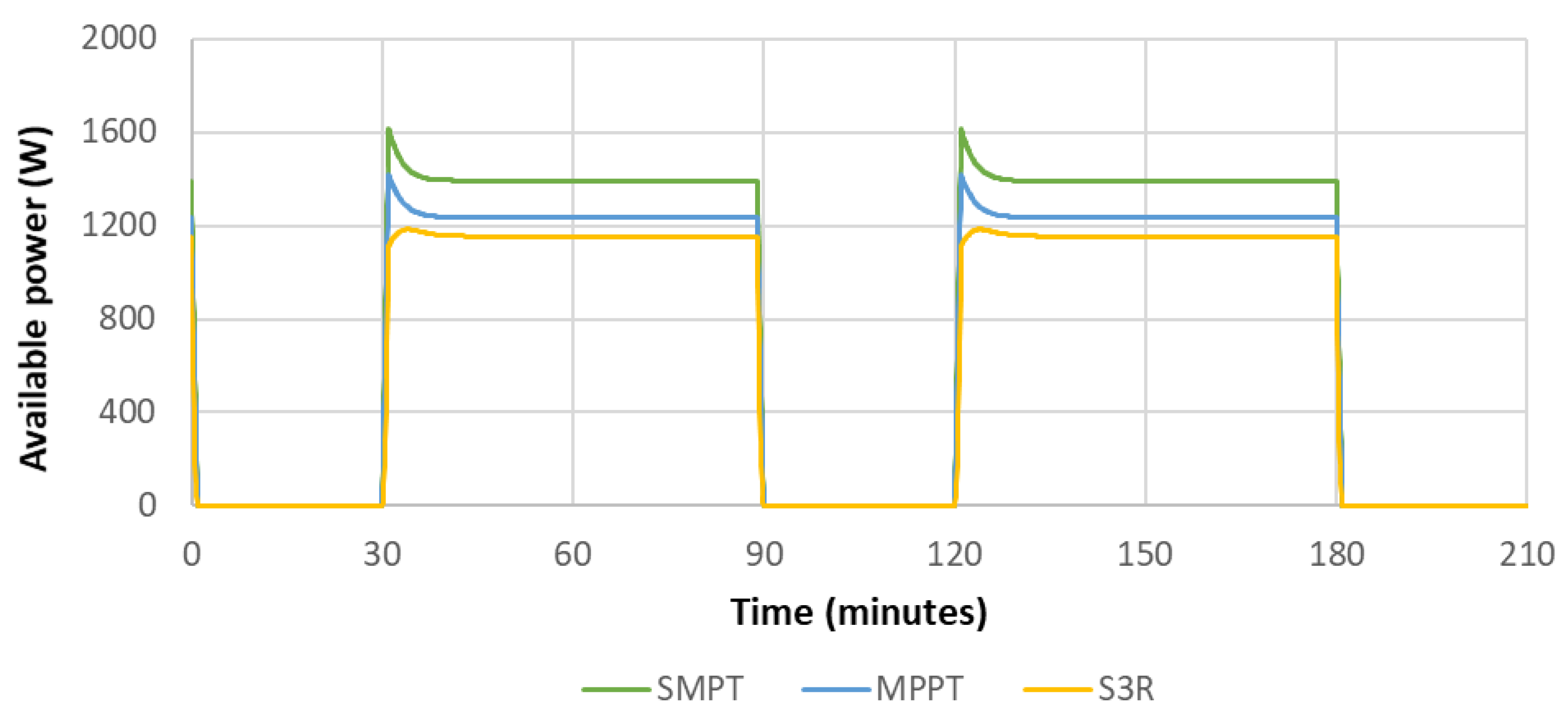
The available power depends on the regulation approach, as reported in
Figure 6. When the loads absorb all available power from the solar array, in S
3R all sections in parallel are tied to the bus voltage; in MPPT all sections in parallel are kept at the voltage corresponding to the maximum power point of the overall solar array; in SMPT optimal energy harvesting is achieved as each section independently is kept at the voltage corresponding to its Maximum Power Point.
The difference between the curves related to SMPT and MPPT is related to mismatching in the solar array: the common node in basic MPPT regulators keeps some sections at a voltage different from their actual V
MP, whereas in the sectional MPPT approaches, such as SMPT regulation, all solar array sections are working at their optimal voltage. Otherwise, in S
3R the operating voltage for solar arrays is fixed independently of the variations of V
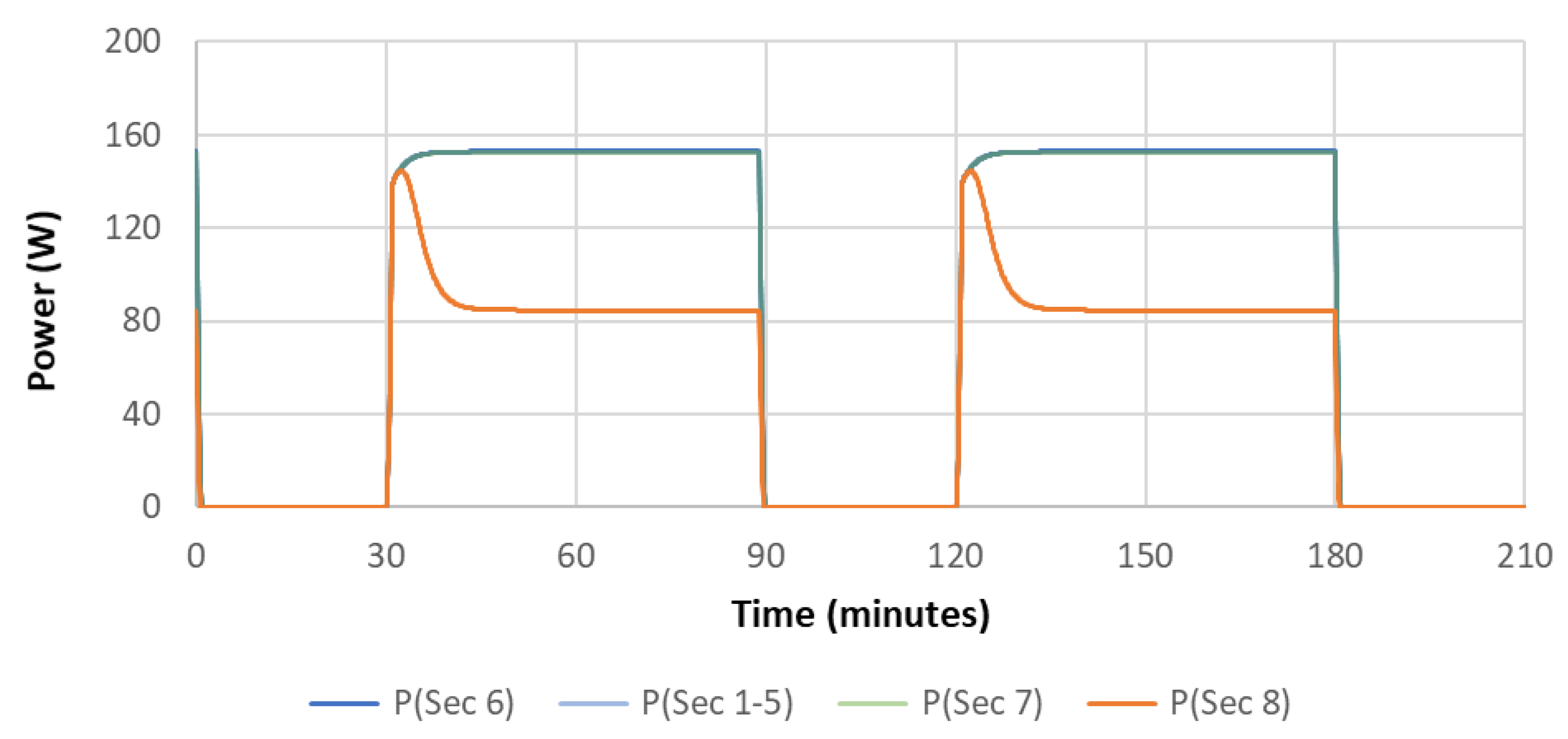
MP. Furthermore, due to the negative thermal coefficient for voltages, after some minutes in sunlight the sections starting with the smaller V
OC may be forced to work in the low-current region of their characteristics, with appreciable power reductions. In
Figure 7 it is clearly seen that this happens for the section 8 in the solar array, whose open-circuit voltage at 25 °C was just 3.3 V larger than the bus voltage.
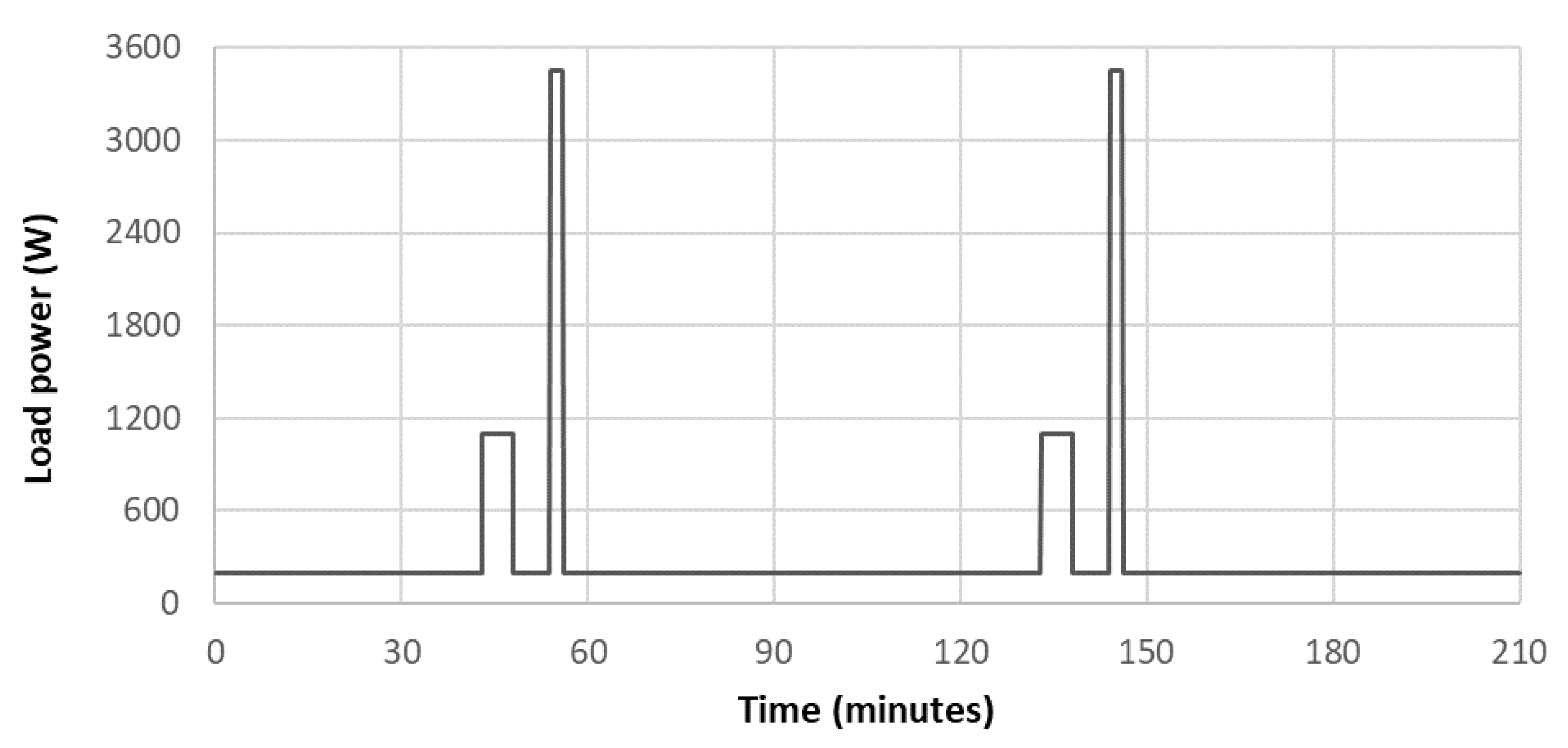
The load profile considered for the spacecraft is reported in
Figure 8. Basic activities absorb 200 W both in sunlight and in eclipse, and periodically the operations of the payload or some spacecraft subsystems result in additional peaks of 900 W for 5 min and 3.2 kW for 1 min. The conversion efficiency was assumed to be 96% for S
3R and 92% for both MPPT-APRs and SMPT-APRs.
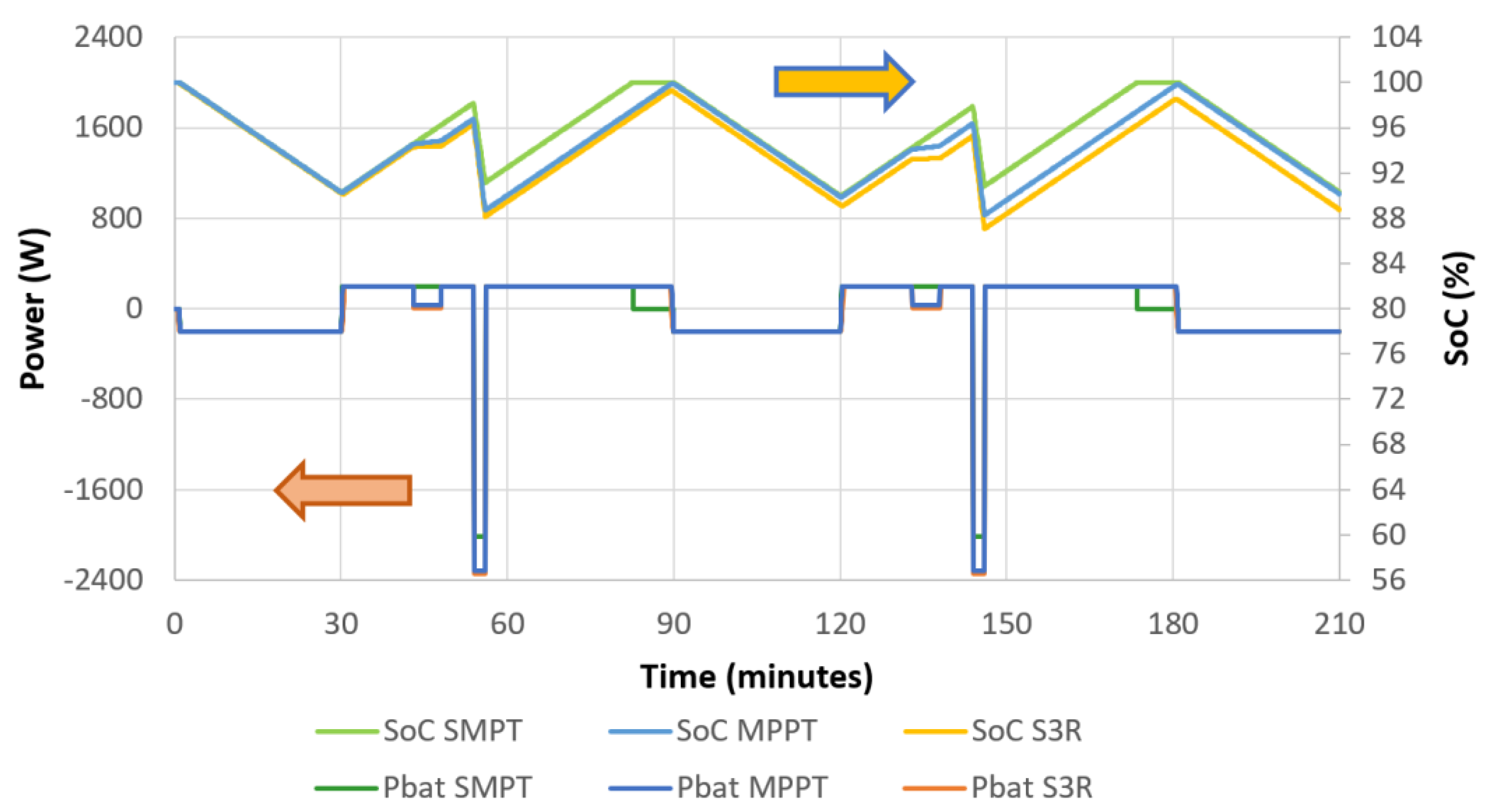
The battery supplies the spacecraft during eclipses and load peaks. During sunlight it absorbs 200 W for recharging, whenever enough power for the purpose is available (see
Figure 9, lower curves, left axis). During the peaks of load absorption, the battery stops charging and, when needed, sustains the load with suitable discharge pulses.
The trend of the battery State of Charge (SoC) (
Figure 9, upper curves, right axis) shows that high load pulses may result in deep cycles in the battery: as expected, the depth of discharge is at a maximum for S
3R. This could affect battery duration [
37] and shall be compensated by increasing the size of the battery.
For the considered case study, the overall amounts of energy per orbit delivered by MPPT and S3R are quite similar, as the larger efficiency of S3R is compensated by the poorer harvesting of the power available on the solar array. For the chosen solar array, the MPPT regulator completes battery recharging with a small margin with respect to the available sunlight time, whereas the S3R regulator is not able to fully recharge the battery recharging: larger solar arrays would be needed to enable energy balance with S3R.
Otherwise, the larger amount of available power, as shown in
Figure 6, enables the SMPT regulator to complete battery recharging well in advance of the next eclipse. It is clear that the case study was specifically built to highlight the strengths of the sectional MPPT approaches such as SMPT, but there is no doubt that these regulation techniques provide clear-cut advantages in terms of performance.
4. SMPT Simulation and Experimental Results
A model of the SMPT regulator was developed in Simulink, aiming to demonstrate the operation of the sequencing algorithm. As shown in
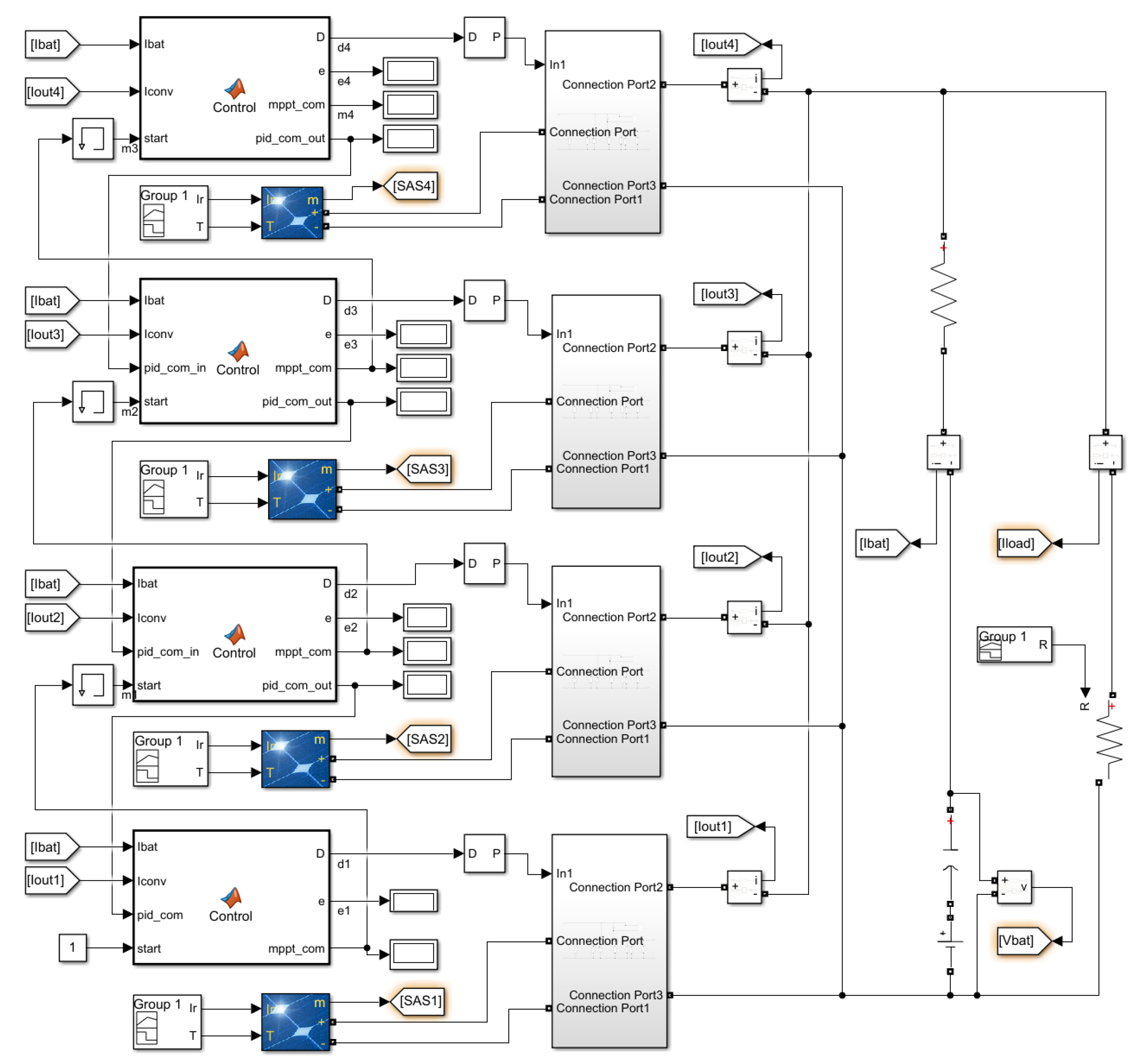
Figure 10, the system consists of four blocks, each comprising a solar array section (in blue), an APR consisting of a dc–dc converter (in grey), and a dedicated controller in charge of managing the SMPT sequence on the basis of the status signals coming from other blocks as well as regulating the APR output current (Iout) to enforce the desired overall control law for the battery and the power bus. All converter outputs are connected in parallel and supply a battery and a variable resistive load.
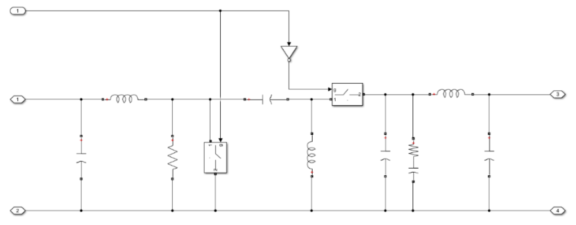
The converter configuration is SEPIC [
39], providing both step-up and step-down operation to allow the solar array sections to operate at voltages across the battery voltage. The circuit embedded in the submodel blocks is reported in
Figure 11.
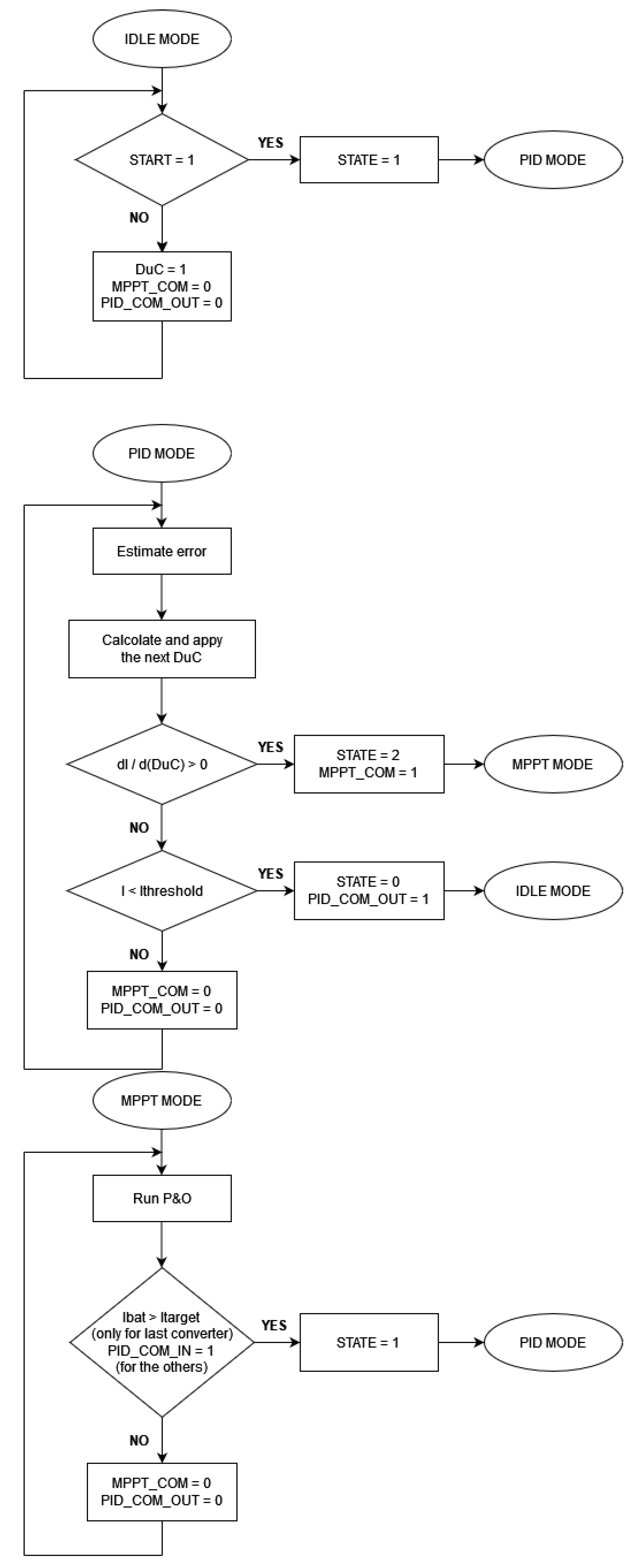
The control block of any APR sets the operating mode according to the observed battery current, to the Duty Cycle (DuC) of the corresponding converter and to the status signals received from other APRs (see
Figure 12). Any single controller can work in three different modes:
State 0: the converter is in IDLE mode, and the controller applies a default Duty Cycle (DuC) of 1, forcing the output of the photovoltaic source in short-circuit. This solution was preferred to the option of getting the idle mode with the source in open-circuit because it allows easier management of the end of eclipses.
State 1: the controller runs the PID algorithm for control, modulating the converter DuC to stabilize the battery charging current.
State 2: the controller is the MPPT mode, running a basic Perturb and Observe (P&O) algorithm, intended to maximize the contribution from the single block, while another APR in the sequence is in charge of fine control.
Changes of state are triggered by the signals shared with the other APRs, namely two signal lines shared with the previous APR in the start-up sequence and one signal line with the next one. More precisely, they are:
the “START” signal. When received in input, forces an APR to exit IDLE mode and start PID control.
the “MPPT_COM” signal, asserted when the APR is in MPPT mode. It sets the START input of the next APR to 1.
the “PID_COM” signal, asserted when the output current of the APR drops below a specified threshold, leading the APR to enter in the IDLE mode. It forces the previous APR in the start-up sequence to stop the MPPT mode and to start the PID control.
In the Simulink model reported in
Figure 10, the PID_COM_IN input and the MPPT_COM output are not provided in the last converter because there is no next converter, while the PID_COM_OUT is not provided in the first converter because there is no previous converter.
Operation is described in detail in the flow chart reported in
Figure 12. An APR enters the PID control mode when it receives a positive level on the START input line. The operating mode passes to MPPT when a Maximum Power Point is detected via a change in the slope of the power-vs-duty cycle trend. At that moment, a START signal is sent to the next APR in the sequence, that enters the PID mode. Otherwise, in case the controller drives the APR output current to zero, the operating mode passes to IDLE and a signal on the PID_COM line forces the previous APR to exit MPPT and start PID mode. Adequate thresholds and hysteresis have been introduced to achieve smooth operation.
The simulation was carried out with the following parameters:
single-section maximum power: 125 W;
Battery start voltage: 26 V;
Nominal charging current: 4 A;
Battery capacity: 1 kWh;
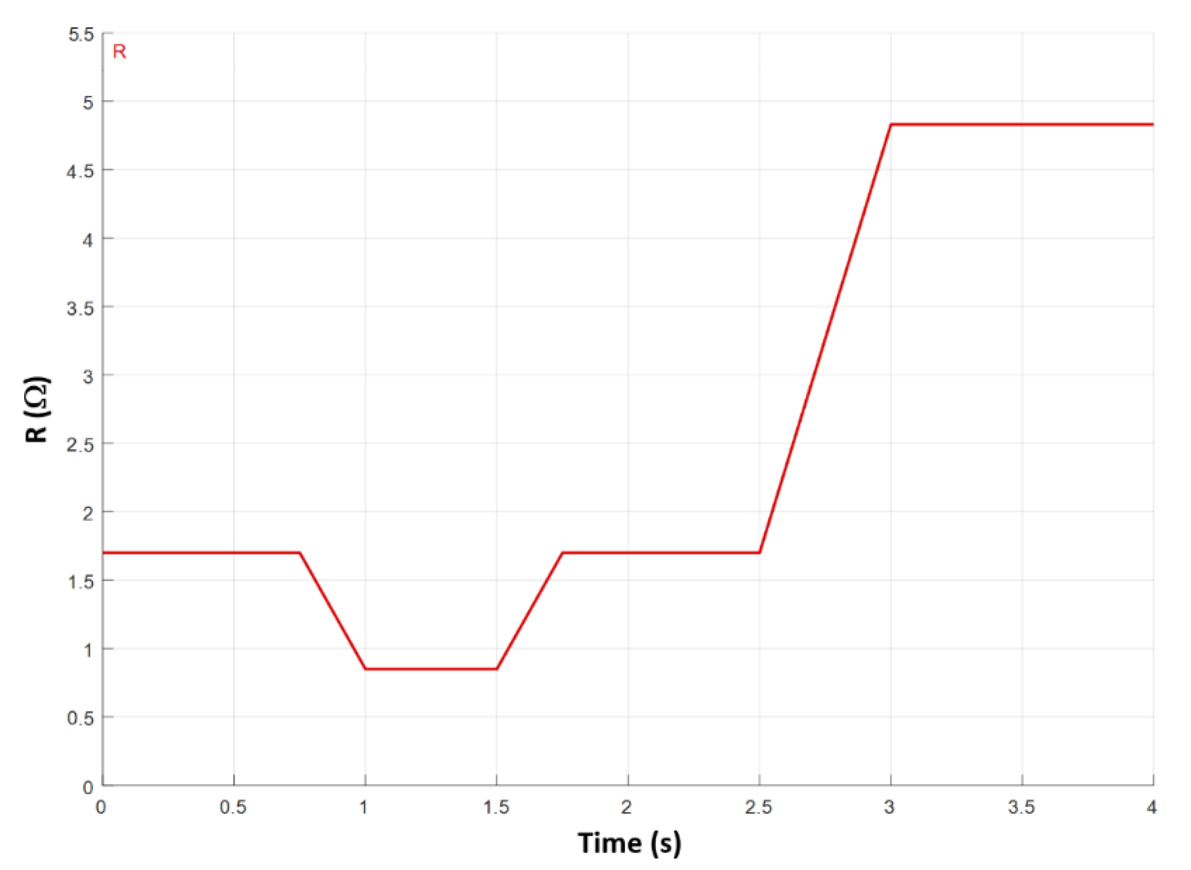
Load sequence (see
Figure 13): 400 W to 800 W to 400 W to 140 W (1.7 Ω to 0.85 Ω to 1.7 Ω to 4.8 Ω);
Discrete, step size 10−7 s.
The system was turned on with the bus absorption at 400 W including the load, and with the charging current for the battery set to 4 A. As depicted in
Figure 14, a first APR, say APR
1, is activated and its output current increases attempting to achieve power balance. After a few tens of milliseconds, its output current reaches its maximum and the APR
1 starts operating in MPPT while the next section is activated in regulation mode. The step is repeated for the solar array sections 2 and 3 until around 0.3 s. The power balance is achieved with APR
4 in regulation mode.
After 0.75 s the load absorption is further increased to 800 W. When APR4 also goes into MPPT, all the available power from the solar array is delivered to the load and the battery starts discharging at nearly 12 A to balance the load demand. The load absorption returns to 400 W at 1.8 s and the previous operating point is quickly recovered. At 2.5 s a further load variation reduces the load absorption to 140 W, and the solar array sections 4 and 3 sequentially quench their outputs. The final equilibrium is found with section 2 in the regulation mode. During the transients, the control on battery current loosens and some deviations with respect to the expected trend are observed. They are particularly evident at 0.75 s, 2.5 s, and 2.7 s. An improved design of the control law will reduce this effect.
The operation of the SMPT algorithm was also experimentally demonstrated by a PCDU breadboard based on SEPIC APR converters. The regulation controller and the SMPT sequencer were both embedded in automotive microcontrollers. A detailed description of the breadboard is out of the scope of this work.
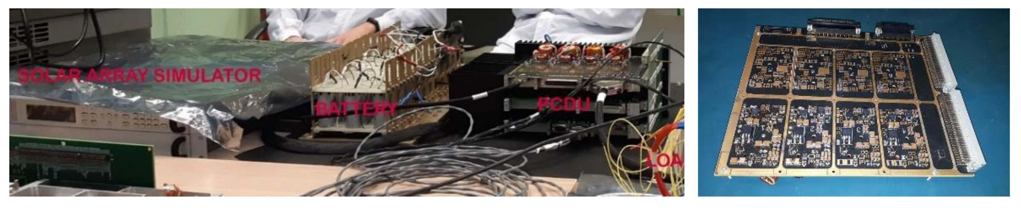
The test setup is shown in
Figure 15. The photovoltaic source was provided by a Keysight E4360 two-channel Solar Array Simulator, with both channels configured as V
OC = 44 V, I
SC = 3.3 A, V
MP = 39.5 V, and I
MP = 3.2 A in order to reproduce the typical current–voltage characteristics of solar array sections consisting of 102 triple-junction solar cells in AM0 conditions [
38], arranged as 6 parallel strings of 17 solar cells in series. The output bus was directly connected to a storage unit consisting of a battery bank with 36 Li-ion cells (size 26650), arranged as 4 parallel strings of 9 cells (4P9S). At the beginning of the tests, the battery was at a voltage V
BAT = 30 V. During the tests, the load was provided by a Hewlett Packard 6060B electronic load, and the overall bus absorption was varied in the range 0–180 W in current-control mode, with the current for battery charging stabilized at 2 A.
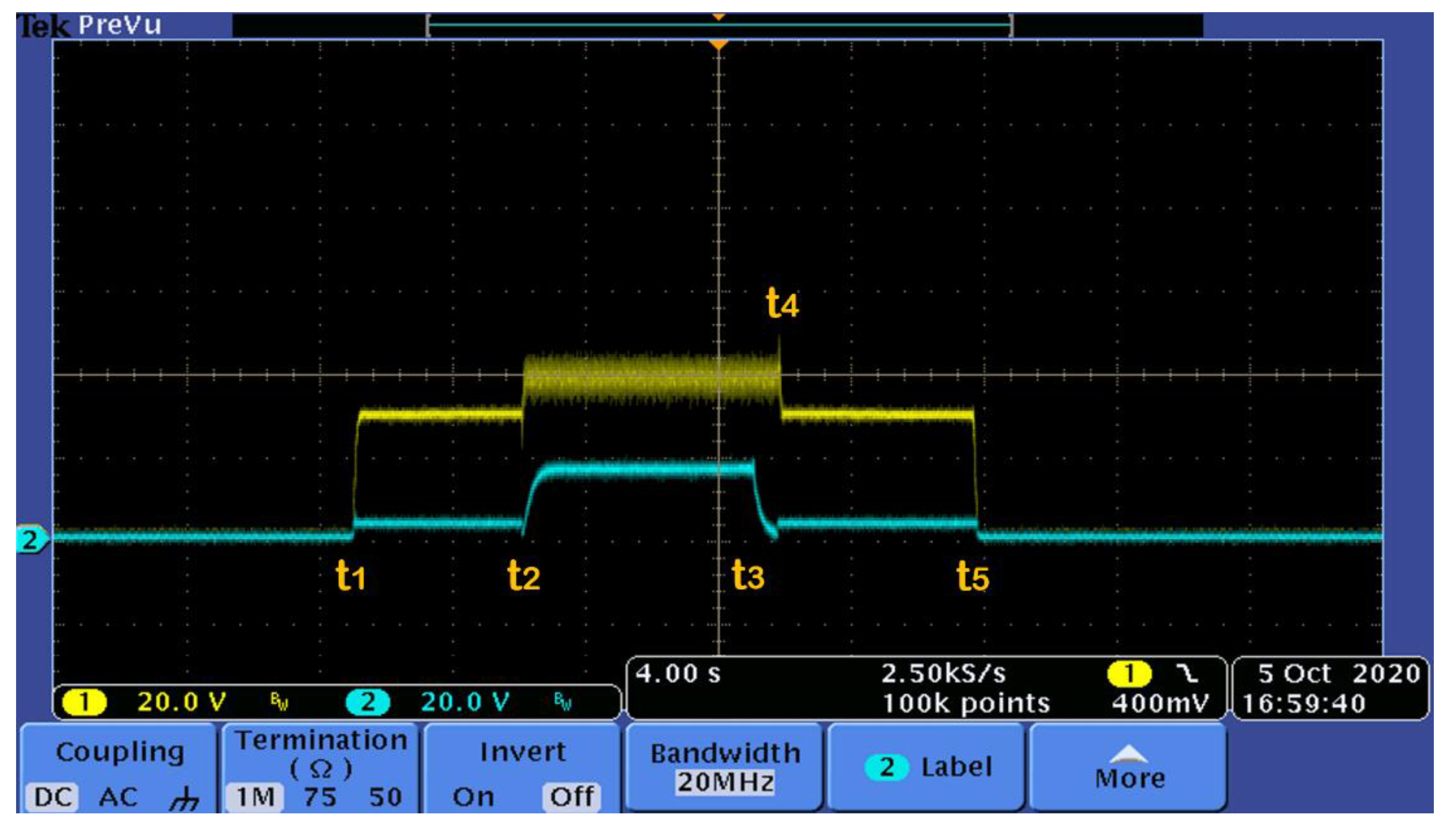
The solar array voltages observed during the tests are shown in
Figure 16. As it is possible to see, the controllers used short-circuit as a starting condition so that the operating point moved in the V < V
MP region, where the current is almost a constant. Therefore, the reported solar array voltage waveforms provide a glance at the input power of the different APRs.
At system turn-ON (t1), the overall output power was POUT < 120 W, resulting from battery charging at 2 A, and an additional 60 W load in parallel. The APR1 (yellow trace) was controlling the charging current, while APR2 (blue trace) was set to a base condition, with output power smaller than 20 W, just to keep the converter in Continuous Conduction Mode. At t2 the load was increased to 120 W (overall output power Pout = 180 W), the APR1 was forced into MPPT, and the control passed to APR2 (blue trace). Then, at t3, the load returned to 60 W: APR1 first kept the MPPT mode until the output power of APR2 went below base power level (at t4), then APR1 started again to operate in the control mode. In the meantime, APR2 was set again to 20 W. The waveforms also show the system turn-off at t5.


 ,
, 


