
Wave Energy Converter’s Slack and Stiff Connection: Study of Absorbed Power in Irregular Waves


Abstract
:1. Introduction
2. Method
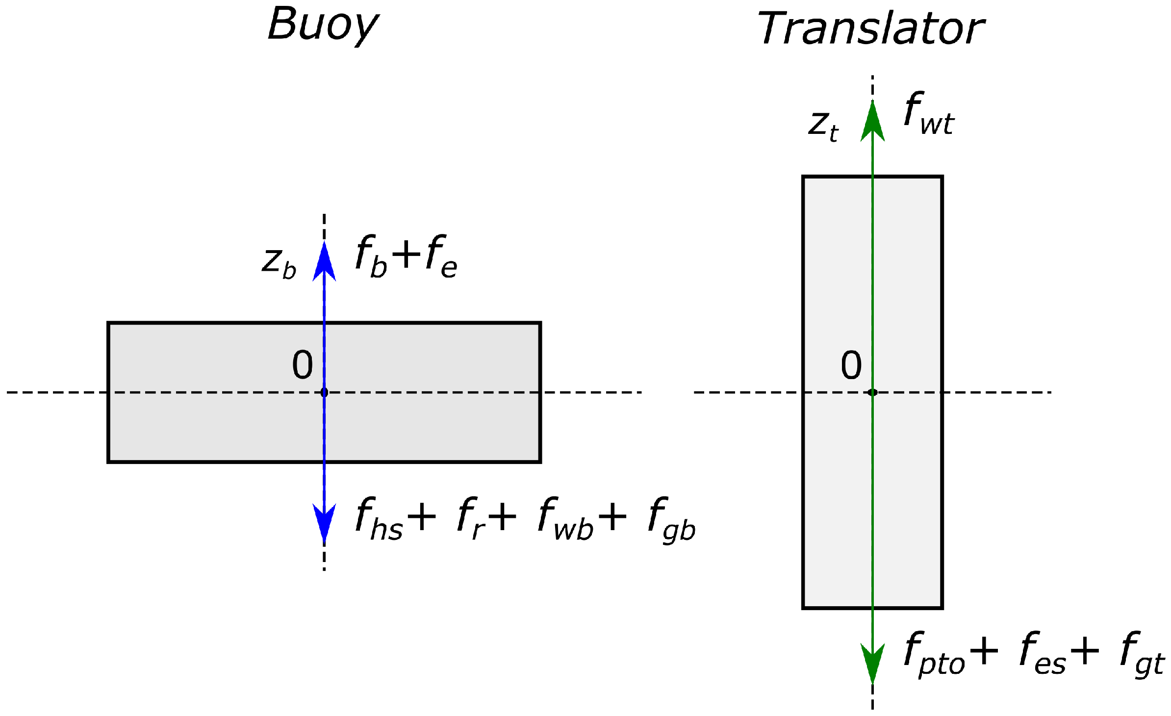
2.1. WEC Model
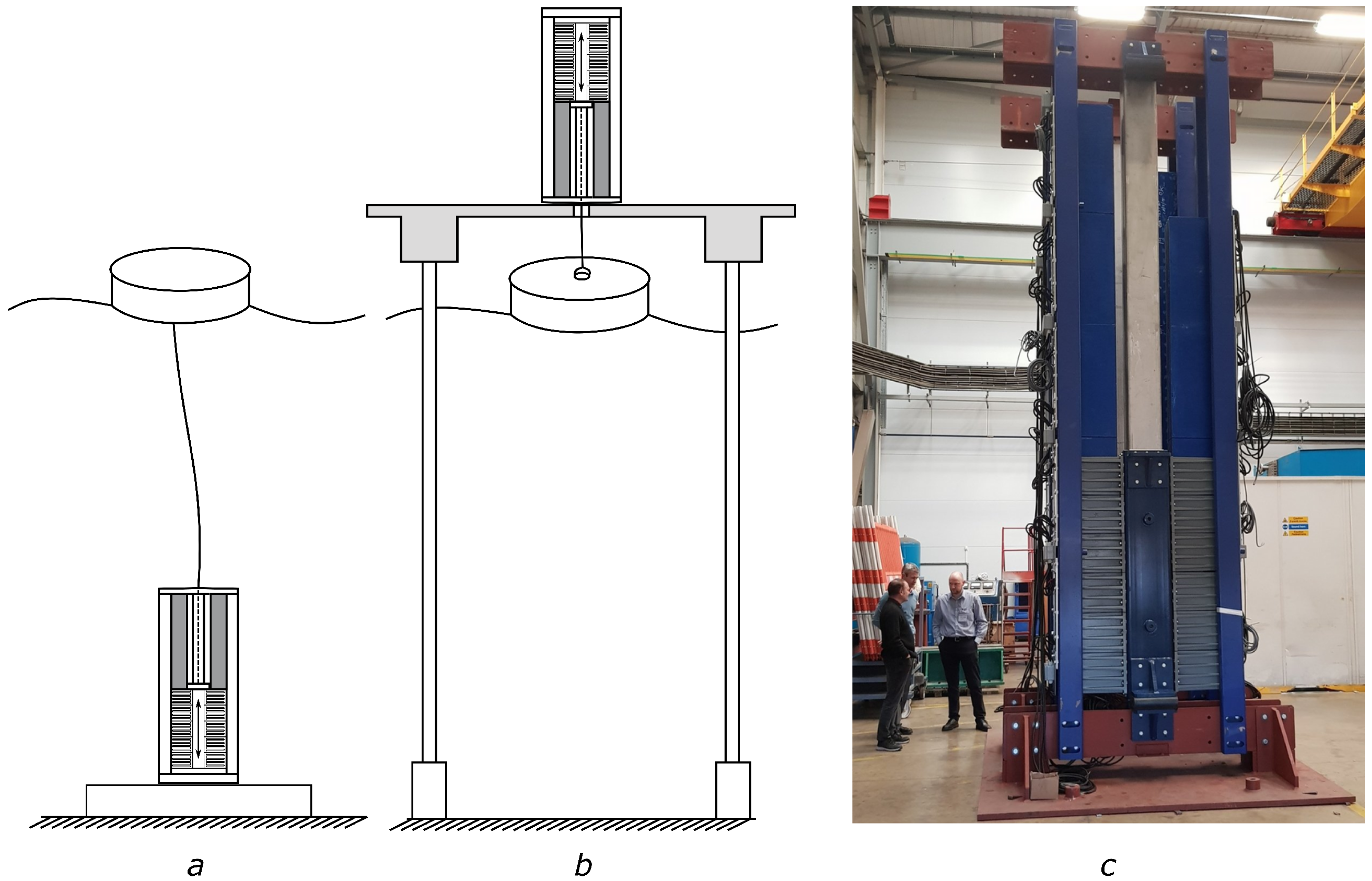
2.1.1. Slack Connection
2.1.2. Stiff Connection
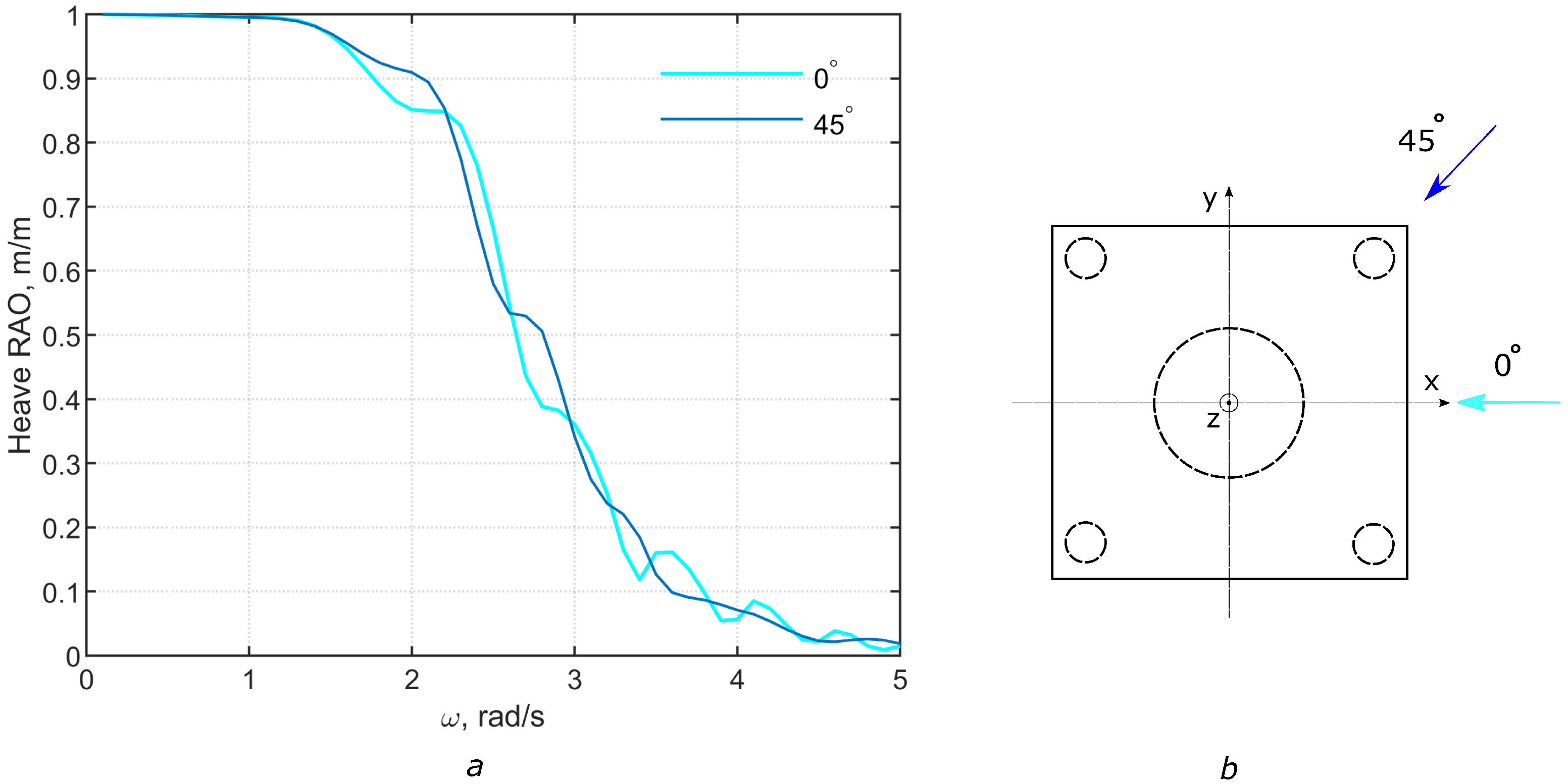
2.2. Hydrodynamic Properties of Buoys
2.3. Damping Force
2.4. Radiation Force
- Damping tends to zero when tends to zero. The difference becomes finite, resulting in .
- Damping tends to zero when tends to infinity. Therefore, .
- Passivity of the system. It ensures that there is no own energy generated by the system, the energy is only stored or dissipated, supplied by the excitation force of the wave. The influence of passivity in linear and nonlinear control systems is shown in [42].
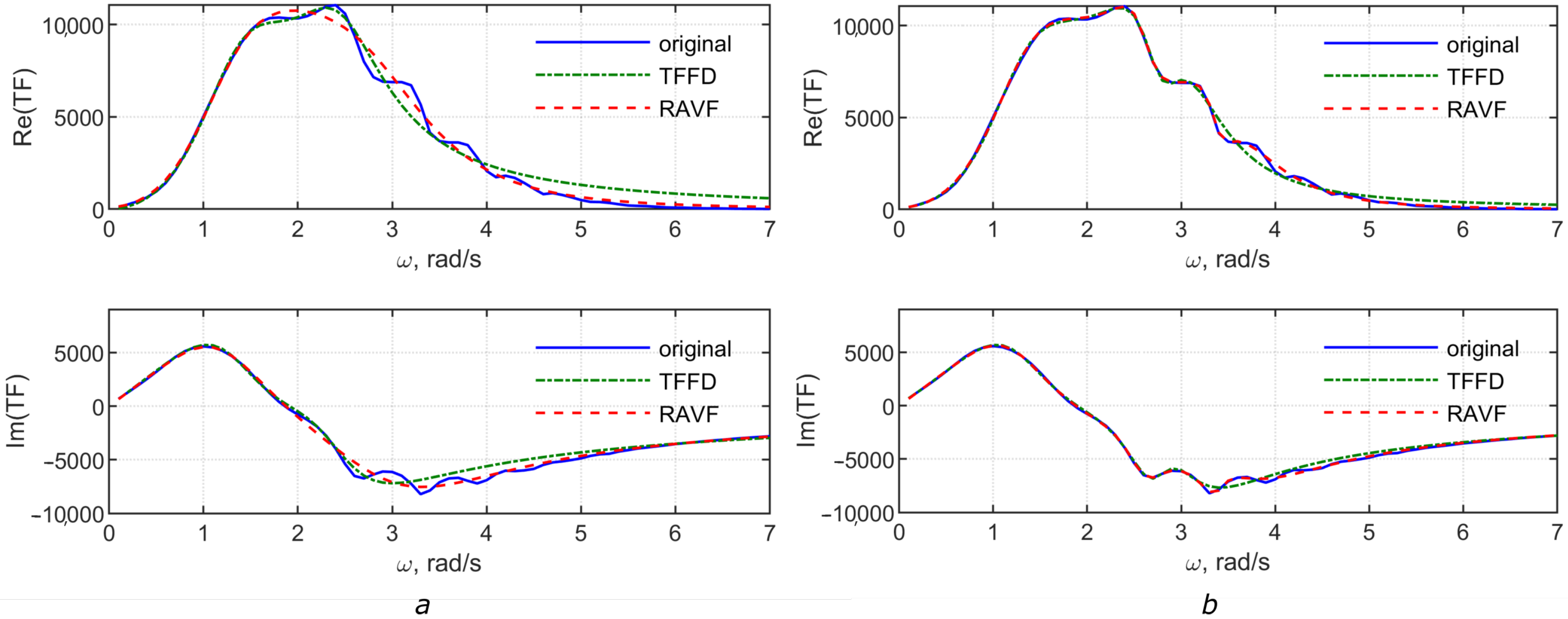
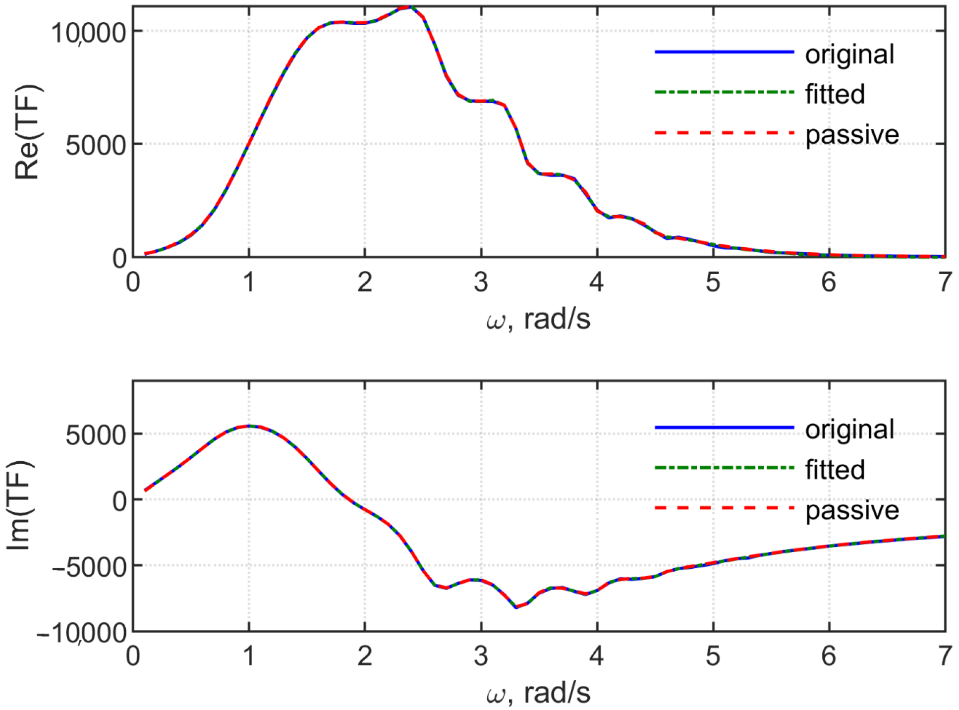
2.4.1. Transfer Function in the Frequency Domain
- Defining the initial weights for the fitting of TF by the rational function;
- Calculation of the hydrodynamic coefficients using the least square method;
- Improving the fit by choosing an appropriate weight vector, corresponding to a minimal chosen error;
- A passivity check; roots with a positive real part are identified, and passivity reinforcement is performed: the sign of negative real parts for the unstable roots is flipped according to the convolution properties described above.
2.4.2. Rational Approximation by Vector Fitting
- Calculation of poles, using the initial given set: a default starting set of poles can be provided as starting poles, in an iterative process these poles are improved;
- Calculation of residues, made by the least square method;
- A passivity check, where the new poles are ensured to be stable and passivity is reinforced; if needed, the sign of the unstable poles’ real parts are inverted.
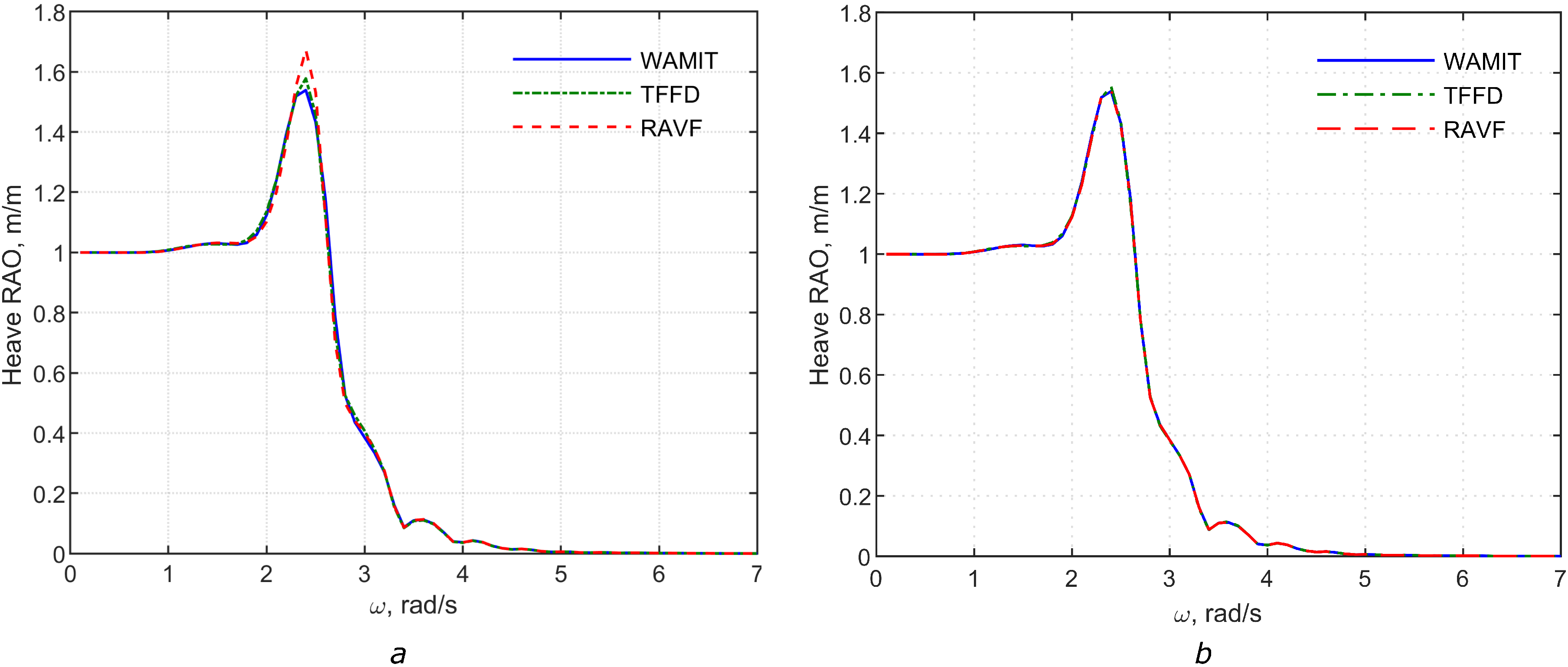
3. Accuracy of the Model
Comparison of the Two Approximations
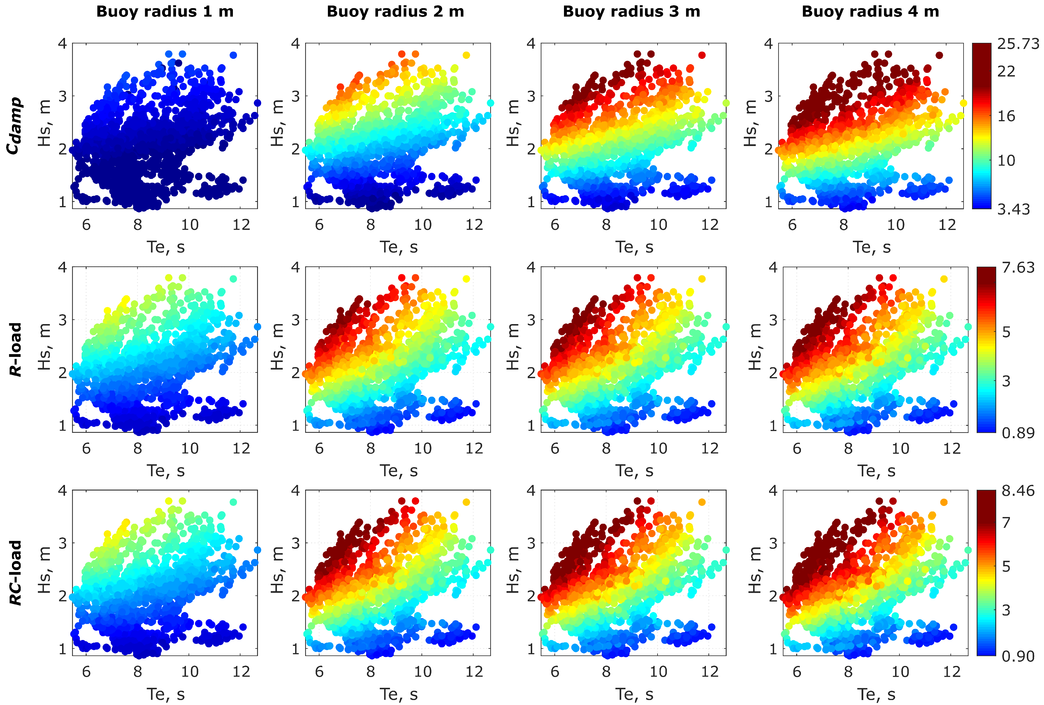
4. Results
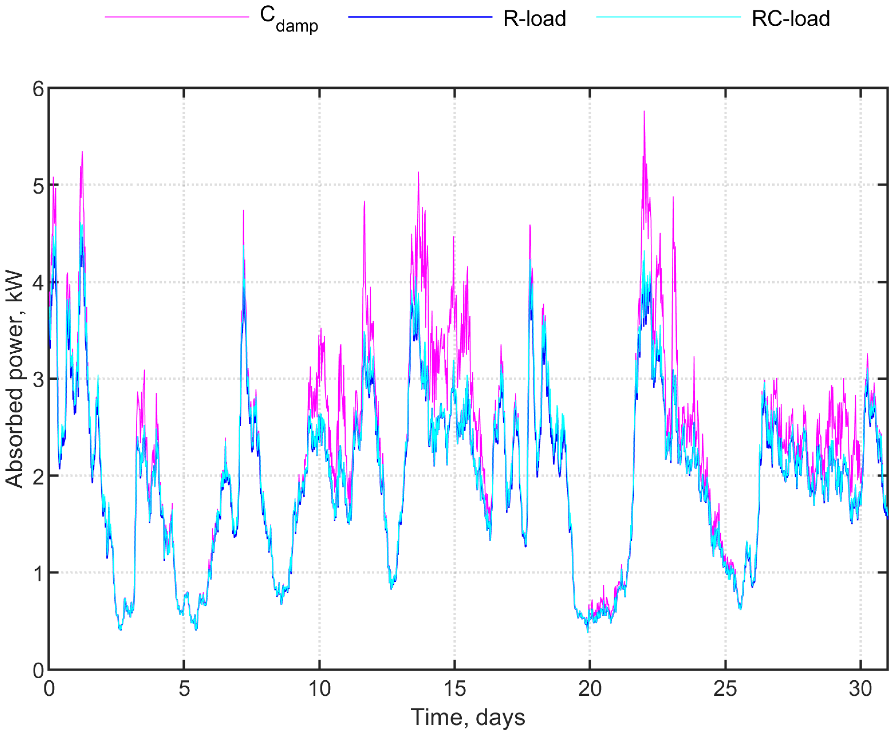
4.1. Irregular Waves
4.2. Absorbed Power
5. Discussion
6. Conclusions
Author Contributions
Funding
Conflicts of Interest
References
- Fairley, I.; Lewis, M.; Robertson, B.; Hemer, M.; Masters, I.; Horrillo-Caraballo, J.; Karunarathna, H.; Reeve, D.E. A classification system for global wave energy resources based on multivariate clustering. Appl. Energy 2020, 262, 114515. [Google Scholar] [CrossRef]
- Xiros, N.I.; Dhanak, M.R. (Eds.) Ocean Wave Energy Conversion Concepts. In Springer Handbook of Ocean Engineering; Springer International Publishing: Cham, Switzerland, 2016; pp. 1117–1146. [Google Scholar] [CrossRef]
- Falcao, A.F. Wave energy utilization: A review of the technologies. Renew. Sustain. Energy Rev. 2010, 14, 899–918. [Google Scholar] [CrossRef]
- Al Shami, E.; Zhang, R.; Wang, X. Point Absorber Wave Energy Harvesters: A Review of Recent Developments. Energies 2019, 12, 47. [Google Scholar] [CrossRef] [Green Version]
- Salter, S. Wave energy: Nostalgic Ramblings, future hopes and heretical suggestions. J. Ocean. Eng. Mar. Energy 2016, 2, 399–428. [Google Scholar] [CrossRef] [Green Version]
- Falcao, A.F.; Henriques, J.C. Oscillating-water-column wave energy converters and air turbines: A review. Renew. Energy 2016, 85, 1391–1424. [Google Scholar] [CrossRef]
- Contestabile, P.; Crispino, G.; Di Lauro, E.; Ferrante, V.; Gisonni, C.; Vicinanza, D. Overtopping breakwater for wave Energy Conversion: Review of state of art, recent advancements and what lies ahead. Renew. Energy 2020, 147, 705–718. [Google Scholar] [CrossRef]
- Alves, M. Wave-to-Wire Modelling of WECs. In Handbook of Ocean Wave Energy; Springer International Publishing: Cham, Switzerlan, 2017; Volume 7. [Google Scholar] [CrossRef]
- Ciappi, L.; Cheli, L.; Simonetti, I.; Bianchini, A.; Manfrida, G.; Cappietti, L. Wave-to-Wire Model of an Oscillating-Water-Column Wave Energy Converter and Its Application to Mediterranean Energy Hot-Spots. Energies 2020, 13, 5582. [Google Scholar] [CrossRef]
- Leijon, M.; Danielsson, O.; Eriksson, M.; Thorburn, K.; Bernhoff, H.; Isberg, J.; Sundberg, J.; Ivanova, I.; Sjostedt, E.; Agren, O.; et al. An electrical approach to wave energy conversion. Renew. Energy 2006, 31, 1309–1319. [Google Scholar] [CrossRef]
- C-Gen Neptune Generator for Wave Energy. Available online: https://www.cgen.eng.ed.ac.uk/ (accessed on 30 January 2021).
- Burchell, J.; Ahmed, N.; Mueller, M.; Galbraith, M.; Barajas-Solano, J. Project Neptune: Critical Component Tests for a Fully Flooded Direct-Drive Linear Generator for Wave Energy Convertors. In Proceedings of the 4th Asian Wave and Tidal Energy Conference, Taipei, Taiwan, 9–13 September 2018. [Google Scholar]
- Eriksson, M.; Waters, R.; Svensson, O.; Isberg, J.; Leijon, M. Wave power absorption: Experiments in open sea and simulation. J. Appl. Phys. 2007, 102, 084910. [Google Scholar] [CrossRef]
- Nguyen, H.; Wang, C.; Tay, Z.; Luong, V. Wave energy converter and large floating platform integration: A review. Ocean. Eng. 2020, 213, 107768. [Google Scholar] [CrossRef]
- Lee, H.; Poguluri, S.K.; Bae, Y.H. Performance Analysis of Multiple Wave Energy Converters Placed on a Floating Platform in the Frequency Domain. Energies 2018, 11, 406. [Google Scholar] [CrossRef] [Green Version]
- Farmer, A.; Whitsel, R.; Hasan, M. Unified Facilities Criteria Program and UFC 4-152-01 Design: Piers and Wharves. In Ports 2019: Port Engineering; American Society of Civil Engineers: Reston, VA, USA, 2019; pp. 715–722. [Google Scholar] [CrossRef]
- Folley, M. Numerical Modelling of Wave Energy Converters; Academic Press: Cambridge, MA, USA, 2016. [Google Scholar] [CrossRef]
- Falnes, J.; Perlin, M. Ocean Waves and Oscillating Systems: Linear Interactions Including Wave-Energy Extraction. Appl. Mech. Rev. 2003, 56, B3. [Google Scholar] [CrossRef]
- Heikkinen, H.; Lampinen, M.J.; Boling, J. Analytical study of the interaction between waves and cylindrical wave energy converters oscillating in two modes. Renew. Energy 2013, 50, 150–160. [Google Scholar] [CrossRef]
- Salter, S.H. Wave power. Nature 1974, 249, 720–724. [Google Scholar] [CrossRef]
- Cummins, W. The Impulse Response Function and Ship Motion; Report No 1661 USA: Department of the Navy, David Taylor Model Basin; MIT: Cambridge, MA, USA, 1962. [Google Scholar]
- Sheng, W. Wave energy conversion and hydrodynamics modelling technologies: A review. Renew. Sustain. Energy Rev. 2019, 109, 482–498. [Google Scholar] [CrossRef]
- Gustavsen, B.; Semlyen, A. Rational approximation of frequency domain responses by vector fitting. IEEE Trans. Power Deliv. 1999, 14, 1052–1061. [Google Scholar] [CrossRef] [Green Version]
- Identification of passive state-space models of strongly frequency dependent wave radiation forces. Ocean. Eng. 2014, 92, 114–128. [CrossRef]
- Skandali, D.; Lourens, E.; Ogink, R. Calibration of response amplitude operators based on measurements of vessel motions and directional wave spectra. Mar. Struct. 2020, 72, 102774. [Google Scholar] [CrossRef]
- Taghipour, R.; Perez, T.; Moan, T. Hybrid frequency–time domain models for dynamic response analysis of marine structures. Ocean. Eng. 2008, 35, 685–705. [Google Scholar] [CrossRef]
- Hong, Y.; Temiz, I.; Pan, J.; Eriksson, M.; Bostrom, C. Damping Studies on PMLG-Based Wave Energy Converter under Oceanic Wave Climates. Energies 2021, 14, 920. [Google Scholar] [CrossRef]
- Nolan, G.; Ringwood, J.; Leithead, W.; Butler, S. Optimal Damping Profiles for a Heaving Buoy Wave Energy Converter. In Proceedings of the International Offshore and Polar Engineering Conference, Seoul, Korea, 19–24 June 2005; Volume 2005. [Google Scholar]
- Falnes, J. Optimum control of oscillation of wave-energy converters. Int. J. Offshore Polar Eng. 2002, 12, 1–9. [Google Scholar]
- Hong, Y.; Waters, R.; Bostrom, C.; Eriksson, M.; Engstrom, J.; Leijon, M. Review on electrical control strategies for wave energy converting systems. Renew. Sustain. Energy Rev. 2014, 31, 329–342. [Google Scholar] [CrossRef]
- Wang, L.; Lin, M.; Tedeschi, E.; Engstrom, J.; Isberg, J. Improving electric power generation of a standalone wave energy converter via optimal electric load control. Energy 2020, 211, 118945. [Google Scholar] [CrossRef]
- Temiz, I.; Eriksson, S.; Leijon, M. Electrical Approach to Output Power Control for a Point Absorbing Wave Energy Converter with a Direct Drive Linear Generator Power Take Off. In Proceedings of the European Wave and Tidal Engineering Conference, Cork, Ireland, 27 August–1 September 2017. [Google Scholar]
- Wave Hub. Available online: https://www.wavehub.co.uk/ (accessed on 30 January 2021).
- Todalshaug, J.H. Hydrodynamics of WECs. In Handbook of Ocean Wave Energy; Pecher, A., Kofoed, J.P., Eds.; Springer International Publishing: Cham, Switzerland, 2017; Volume 7. [Google Scholar] [CrossRef] [Green Version]
- Potapenko, T.; Temiz, I.; Leijon, M. Optimization of resistive load for a wave energy converter with linear generator power take off. In Proceedings of the 4th Asian Wave and Tidal Energy Conference, Taipei, Taiwan, 9–13 September 2018. [Google Scholar]
- Cummins, W. The Impulse Response Function and Ship Motion. Schiffstechnik 1962, 47, 101–109. [Google Scholar]
- Fossen, T. Marine Control Systems: Guidance, Navigation and Control of Ships, Rigs and Underwater Vehicles; Marine Cybernetics: Trondheim, Norway, 2002; Volume 28. [Google Scholar]
- Duarte, T.; Sarmento, A.; Alves, M.; Jonkman, J. State-Space Realization of the Wave-Radiation Force within FAST: Preprint; National Renewable Energy Lab. (NREL): Golden, CO, USA, 2013. [Google Scholar] [CrossRef] [Green Version]
- Duke, E. Combining and Connecting Linear, Multi-Input, Multi-Output Subsystem Models; NASA Technical Memorandum 85912; NASA: Edwards, CA, USA, 1986. [Google Scholar]
- Gustavsen, B. Improving the pole relocating properties of vector fitting. IEEE Trans. Power Deliv. 2006, 21, 1587–1592. [Google Scholar] [CrossRef]
- Deschrijver, D.; Mrozowski, M.; Dhaene, T.; De Zutter, D. Macromodeling of Multiport Systems Using a Fast Implementation of the Vector Fitting Method. IEEE Microw. Wirel. Compon. Lett. 2008, 18, 383–385. [Google Scholar] [CrossRef] [Green Version]
- Kottenstette, N.; McCourt, M.J.; Xia, M.; Gupta, V.; Antsaklis, P.J. On relationships among passivity, positive realness, and dissipativity in linear systems. Automatica 2014, 50, 1003–1016. [Google Scholar] [CrossRef]
- Identify Continuous-Time Filter Parameters from Frequency Response Data. Available online: https://se.mathworks.com/help/signal/ref/invfreqs.html (accessed on 30 January 2021).
- Levy, E.C. Complex-curve fitting. IRE Trans. Autom. Control. 1959, AC-4, 37–43. [Google Scholar] [CrossRef]
- Deschrijver, D.; Gustavsen, B.; Dhaene, T. Advancements in Iterative Methods for Rational Approximation in the Frequency Domain. IEEE Trans. Power Deliv. 2007, 22, 1633–1642. [Google Scholar] [CrossRef]
- Ciappi, L.; Cheli, L.; Simonetti, I.; Bianchini, A.; Talluri, L.; Cappietti, L.; Manfrida, G. Wave-to-wire models of wells and impulse turbines for oscillating water column wave energy converters operating in the Mediterranean Sea. Energy 2022, 238, 121585. [Google Scholar] [CrossRef]
- Van Nieuwkoop-McCall, J.; Smith, H.; Smith, P.G.; Johanning, L. Long-term hindcast for Wave Hub, Cornwall: Validation and analysis of modelled results. In Report Conducted for the TSB Project: Accelerated Development of the PB500 for Deployment at Wave Hub; University of Exeter: Exeter, UK, 2012. [Google Scholar]
- Quality Control of Wave Data 2016. Available online: https://www.channelcoast.org/ccoresources/dataqualitycontrol/QC_Manual_CCO_Waves.pdf (accessed on 30 January 2021).
- Falnes, J. Ocean Waves and Oscillating Systems: Linear Interactions Including Wave-Energy Extraction; Cambridge University Press: Cambridge, UK, 2002. [Google Scholar] [CrossRef]
- Babarit, A. A database of capture width ratio of wave energy converters. Renew. Energy 2015, 80, 610–628. [Google Scholar] [CrossRef] [Green Version]
- Tan, J.; Polinder, H.; Laguna, A.J.; Wellens, P.; Miedema, S.A. The Influence of Sizing of Wave Energy Converters on the Techno-Economic Performance. J. Mar. Sci. Eng. 2021, 9, 52. [Google Scholar] [CrossRef]


| Parameters | Values |
|---|---|
| Mass of Translator | 5600 kg |
| Number of stages | 4 |
| Translator length | 2 m |
| Stroke length | 3 m |
| Pole width | 0.083 m |
| Number of coils | 18 |
| Number of turns | 258 |
| Number of poles | 24 |
| Peak velocity | 1 m/s |
| Phase Voltage, rms | 240 V |
| Windings phase resistance | 13.35 |
| Windings phase inductance | 0.21 H |
| Flux density of airgap | 0.45 T |
| Radius, m | Draft, m | Height, m | Mass, kg |
|---|---|---|---|
| 1 | 2.4 | 3.5 | 2200 |
| 2 | 0.7 | 2 | 3000 |
| 3 | 0.3 | 1 | 4000 |
| 4 | 0.2 | 1 | 6000 |
| N | Time, s | |||||
|---|---|---|---|---|---|---|
| TFFD | RAVF | TFFD | RAVF | TFFD | RAVF | |
| 3 | 0.9959 | 0.7908 | 0.7273 | 7.5642 | 0.0935 | 2.1992 |
| 4 | 0.9997 | 0.9989 | 0.0446 | 0.0848 | 0.0211 | 0.7260 |
| 5 | 0.9996 | 0.7925 | 0.0005 | 26.9476 | 0.0153 | 0.8855 |
| 6 | 0.9999 | 0.9999 | 0.0268 | 0.0828 | 0.1129 | 0.6632 |
| 7 | 0.9999 | 0.6079 | 0.0221 | 51.5098 | 0.0771 | 0.7957 |
| 8 | 0.9999 | 0.9999 | 0.0159 | 0.0607 | 182.18 | 0.6523 |
| 9 | − | 0.9999 | − | 0.0686 | − | 0.6288 |
| 10 | − | 0.9878 | − | 1.5843 | − | 1.7884 |
| 11 | − | 0.7368 | − | 7.5926 | − | 0.8021 |
| 12 | − | 0.8741 | − | 2.6359 | − | 0.7282 |
| 13 | − | 0.9995 | − | 0.4739 | − | 0.6668 |
| 14 | − | 0.9017 | − | 4.5169 | − | 0.7067 |
| 15 | − | 0.7720 | − | 0.5195 | − | 0.7279 |
| 16 | − | 0.9999 | − | 0.0532 | − | 3.5091 |
| 17 | − | 0.9976 | − | 0.6541 | − | 1.4792 |
| 18 | − | 0.9999 | − | 0.0362 | − | 0.7475 |
| 19 | − | 0.4588 | − | 20.67 | − | 0.7801 |
| 20 | − | 0.9999 | − | 0.0321 | − | 1.9464 |
| 21 | − | 0.9992 | − | 0.4968 | − | 0.8284 |
| 22 | − | 0.9999 | − | 0.0402 | − | 0.7147 |
| 23 | − | 0.9999 | − | 0.0349 | − | 0.6947 |
| 24 | − | 0.9999 | − | 0.0487 | − | 0.7139 |
| 25 | − | 0.9999 | − | 0.0315 | − | 0.7282 |
| N | Time, s | |||||
|---|---|---|---|---|---|---|
| TFFD | RAVF | TFFD | RAVF | TFFD | RAVF | |
| 3 | 0.9992 | 0.9982 | 0.0708 | 1.1462 | 0.0865 | 2.3621 |
| 4 | 0.1964 | 0.9987 | 7 | 1.2971 | 0.0194 | 0.8734 |
| 5 | 0.1964 | 0.9991 | 4 | 0.8850 | 0.0114 | 0.8990 |
| 6 | 0.1964 | 0.9991 | 10 | 1.2095 | 0.0276 | 0.7253 |
| 7 | 0.1964 | 0.9991 | 2.5 | 1.1208 | 0.0674 | 0.7466 |
| 8 | − | 0.9998 | − | 0.9605 | − | 0.6875 |
| 9 | − | 0.9997 | − | 1.1580 | − | 0.7518 |
| 10 | − | 0.9999 | − | 0.7258 | − | 0.7378 |
| 11 | − | 0.9998 | − | 0.8217 | − | 0.7028 |
| 12 | − | 0.9998 | − | 0.8386 | − | 0.7286 |
| 13 | − | 0.9999 | − | 0.7882 | − | 0.7305 |
| 14 | − | 0.9997 | − | 1.0562 | − | 0.7556 |
| 15 | − | 0.9991 | − | 0.8054 | − | 0.8148 |
| Concept | , m | , kW | , kW | , kW | , % | , % | , % |
|---|---|---|---|---|---|---|---|
| 1 | 2.12 | 1.92 | 1.95 | 10.49 | 9.49 | 9.62 | |
| Slack | 2 | 7.57 | 3.61 | 3.80 | 18.71 | 8.93 | 9.39 |
| connection | 3 | 10.91 | 3.83 | 4.08 | 18.98 | 6.32 | 6.72 |
| 4 | 12.89 | 3.96 | 4.23 | 15.94 | 4.90 | 5.24 | |
| 1 | 2.22 | 1.97 | 2.00 | 10.96 | 9.75 | 9.89 | |
| Stiff | 2 | 8.22 | 3.66 | 3.87 | 20.33 | 9.06 | 9.58 |
| connection | 3 | 20.63 | 3.86 | 4.13 | 34.01 | 6.36 | 6.80 |
| 4 | 32.04 | 3.76 | 4.03 | 39.62 | 4.65 | 4.98 |
| Concept | , m | , kW | , kW | , kW |
|---|---|---|---|---|
| 1 | 72.58 | 45.08 | 47.49 | |
| Slack | 2 | 336.81 | 73.50 | 76.85 |
| connection | 3 | 588.60 | 84.95 | 88.04 |
| 4 | 1032.91 | 84.27 | 85.80 | |
| 1 | 78.45 | 46.92 | 46.81 | |
| Stiff | 2 | 310.11 | 65.93 | 68.96 |
| connection | 3 | 1058.40 | 64.83 | 69.68 |
| 4 | 1373.41 | 77.74 | 80.90 |
Publisher’s Note: MDPI stays neutral with regard to jurisdictional claims in published maps and institutional affiliations. |
© 2021 by the authors. Licensee MDPI, Basel, Switzerland. This article is an open access article distributed under the terms and conditions of the Creative Commons Attribution (CC BY) license (https://creativecommons.org/licenses/by/4.0/).
Share and Cite
Potapenko, T.; Burchell, J.; Eriksson, S.; Temiz, I. Wave Energy Converter’s Slack and Stiff Connection: Study of Absorbed Power in Irregular Waves. Energies 2021, 14, 7892. https://doi.org/10.3390/en14237892
Potapenko T, Burchell J, Eriksson S, Temiz I. Wave Energy Converter’s Slack and Stiff Connection: Study of Absorbed Power in Irregular Waves. Energies. 2021; 14(23):7892. https://doi.org/10.3390/en14237892
Chicago/Turabian StylePotapenko, Tatiana, Joseph Burchell, Sandra Eriksson, and Irina Temiz. 2021. "Wave Energy Converter’s Slack and Stiff Connection: Study of Absorbed Power in Irregular Waves" Energies 14, no. 23: 7892. https://doi.org/10.3390/en14237892
APA StylePotapenko, T., Burchell, J., Eriksson, S., & Temiz, I. (2021). Wave Energy Converter’s Slack and Stiff Connection: Study of Absorbed Power in Irregular Waves. Energies, 14(23), 7892. https://doi.org/10.3390/en14237892