Abstract
To use lithium-iron-phosphate battery packs in the supply systems of any electric mining equipment and/or machines, the required conditions of work safety must be met. This applies in particular to coal mines endangered by fire and/or explosion. To meet the spark-safety conditions, the cells (together with the battery management system—BMS) must be isolated from the influence of the environment, and therefore placed in special fire-tight housings. This significantly degrades the heat dissipation, thus affecting the operating conditions of the cell-packs. Therefore, their usage without the so-called BMS is not recommended, as shown in the authors’ preliminary research. In practice, various BMS are used, most often with the so-called passive balancing. However, their application in mines is uncertain, due to the effect of heating under operation. When it comes to active BMS, they usually possess a quite complex structure and hence, are relatively expensive. Therefore, the authors conducted research for two specially developed active and one commercial passive BMS cooperating with selected lithium-iron-phosphate (LiFePO4) batteries when used in a suspended mining vehicle type PCA-1. The tests were carried out under environmental temperatures ranging from +5 °C to +60 °C. The effect of mismatching (12.5% to 37.5% of total cells number) of the cell parameters on the temperature distribution and voltage fading at the terminals of individual cells was checked. As a result of the investigations, the practical usefulness of the developed active BMS was determined, enabling the extension of the lithium-iron-phosphate battery life under onerous mine conditions, for a single recharge, which is a novelty. On the basis of the obtained results, appropriate practical conclusions were formulated.
1. Introduction
Since diesel and/or gas engines produce pollution (exhaust emission), such machines are seldom employed nowadays in hard coal mines [1]. For mining, as well as for coal transport, the electric machines, are mainly used (particularly in deep mines) [2,3]. Electrically supplied machines reduce the importance of ventilation (no exhaust emission), but their application is also limited [4,5]. This is due to limitations of battery capacity (for battery machines), the technical difficulties of running traction underground (for traction locomotives) and limitations due to length and electrical parameters of the cable connecting belt conveyors and/or suspended vehicles. As there is currently no alternative to battery machines and/or electric traction, the efficiency of both locomotives and electric vehicles should be increased to use them more effectively. This can be achieved by improving the efficiency of the power supply and control system, and/or by modifying the drive system as well. Most locomotives and battery vehicles in mines are currently powered by lead-acid batteries [6,7]. Lead-acid batteries are large sized, and have a relatively long loading time. The only practical advantage is their weight, which makes increased contact force of the traction locomotive’s wheels to the rails possible, resulting in substantial locomotive driving force values. In the case of suspended mining machines, this problem is reversed. The significant development of secondary cells makes the use of batteries from the lithium group possible [8]. They display much better electrical properties, but unfortunately are much more expensive. Furthermore, they have to be appropriately safeguarded to allow for use in the onerous environment of natural hazards (methane, temperature, water and/or fire). Currently, underground mining around the world is carried out at greater and greater depths, with an increasing geothermal degree of the rock mass (above 40 °C). The increased temperature deteriorates not only work safety, but also increases the failure rate of installed machines and devices. The key problem is, therefore, to prevent damage to these mining machines and devices powered by lithium batteries, especially in environments endangered by methane and/or coal dust explosion [9]. The protection must be so designed that the damage does not result in electrolyte decomposition increasing gas pressure inside the cell. Such a situation may encourage ignition of the cell or the gas emission which can lead to cell explosion. This means that lithium batteries should be handled to prevent decomposition under the rated conditions. Therefore, they should only be used within the safe range of voltage, current and temperature as specified by the manufacturer. For lithium batteries to operate as long and as safely as possible, they are often equipped with the appropriate supervisory electronic modules. They are marked as BMS [10,11]. Their task is to prevent damage to the cells due to overcharging, excessive discharge and/or overheating [12].
Lithium batteries are very sensitive, above all, to total and/or so-called deep discharging. If left in such a state for a long time, they may be irreversibly damaged. The voltage value than falls below the threshold specified by the manufacturer which results in damage of the crystal structure of the cells. Further charging becomes impossible [13]. Therefore, the BMS should control the operating parameters of the cells and, if they are exceeded (i.e., current, voltage, temperature), it should alert or disconnect the battery [14]. Nevertheless, an important function of the BMS is to balance (equalize) the cells used to increase their efficiency and lifetime [15]. The need for balancing follows from the differences in the level of charge, capacity and resistance values of the individual cells of the battery which is assembled. These differences are due to manufacturing tolerances and operating conditions, and show a tendency to increase with the lifetime. It should be emphasized here that as a result of variation in the capacity value over time, the “weaker” cells are being overloaded during charging. This can lead to their failure and, consequently, damage to the assembled battery. For if at least one cell is mismatched and possesses a lower capacity, its capacity value determines the total capacity of the battery [16].
In [17] presents a critical review of state of battery health monitoring methods for electrical vehicles. Based on a battery model, model-based estimation methods identify the parameters, which have certain relationships with battery aging level, to realize the state of health estimation [18]. The short circuit of a battery has been considered as one of the main causes of a large number of accidents. Therefore, diagnosing and prognosticating short circuit are of great significance to improve electric vehicle safety. In [19], the authors underline that the effectiveness of electric vehicles depends on the accurate assessment of key parameters, as well as proper functionality and diagnosis of the battery storage system. However, poor monitoring and safety strategies of the battery storage system can lead to critical issues such as battery overcharging, over-discharging, overheating, cell unbalancing, thermal runaway, and fire hazards. To address these concerns, an effective BMS plays a crucial role in enhancing battery performance, including precise monitoring, charging-discharging control, heat management, battery safety, and protection [20]. Authors consider that cell matching is an important first step required for the safe operation of multicell lithium–iron–phosphate batteries. Cell mismatch can occur due to battery overdischarge, overcharge, internal and external shorts, etc., or even when leaving a battery unused for an extended period (calendar aging). Predicting a mismatch is essential for a battery’s thermal safety and electrical efficiency. Conventional BMSs typically monitor cell voltages and surface temperature. However, these measurements and related protocols have not succeeded in ensuring battery safety or improving efficiency. Data for batteries with intentionally calendar-aged and overdischarged cells convincingly demonstrate that such BMSs cannot identify cell mismatches and emerging failures. In contrast, the impedance based BMS tracks, identifies, and acts on changes in the internal state of each cell continuously in real time, including when battery charging, discharging, and at rest [21]. It has been confirmed that the performance of a string of series-connected batteries is typically restricted by the worst cell in the string, and a single failure point will render the entire string unusable. To address these issues, a decentralized BMS with no communication requirement is presented, based on a modular multilevel converter topology with a distributed inductor and distributed controller running on a local microprocessor. It is experimentally shown that a system of three smart cells with their decentralized controllers can accurately synchronize the state of charge (SoC) [22] while minimizing their output voltage ripple [23]. The paper claims that aging increases the internal resistance of a battery and reduces its capacity; therefore, energy storage systems (ESSs) require a BMS algorithm that can manage the state of the battery. This paper proposes a battery efficiency calculation formula to manage the battery state. The proposed battery efficiency calculation formula uses the charging time, charging current, and battery capacity. An algorithm that can accurately determine the battery state is proposed by applying the proposed SoC and state of health (SoH) calculations [24]. Other studies have addressed similar research topics. They are also concerned with the problem of replacing lead batteries with LiFePO4 lithium-iron-phosphate batteries but in vehicles. However, they focus on tests for passive balancing. The BMS detects when the battery pack is charged and it enables passive balancing of charged cells, which are bypassed through high power resistors. The measured parameters (voltages, current, and temperature) and charging/discharging states can be displayed on LCD and transmitted to other Electronic Control Units (ECUs) using Controller Area Networks (CAN).
The article presents and discusses the results of research on the performance of a lithium battery consisting of lithium–iron–phosphate (LiFePO4) cells when equipped with passive and/or selected active BMS. Due to the intended use in underground mines, the tests were carried out both at room temperature (20 °C) and free cooling, as well as for deteriorated cooling at various mine ambient temperatures (from +5 °C to +60 °C) at constant humidity 75%. Particular attention was paid to the efficiency of the battery performance with the developed active BMS used. The tests were carried out for a battery arranged with eight cells connected in series as an example. The conditions for mismatching of certain parts of cells in the battery were simulated experimentally by forced differences in cell capacity from one (12.5%) to three (37.5%) cells, respectively, to demonstrate the need for an active BMS. On the basis of the results, the usefulness of the developed active BMS (by the battery to cell method) in practice was determined, enabling the extension of the lithium–iron–phosphate battery life for a single recharge, what is a novelty. The solutions of BMS used in practice have been briefly classified in Section 2. The development of active BMS by the authors is presented and discussed in detail in Section 3. The scope and method of the conducted research is in turn described in Section 4. The results of the investigations are presented and discussed in Section 5. On the basis of the results obtained from the measurements of electrical quantities and cell temperature, appropriate conclusions for use in practice are formulated in Section 6. They have been specified regarding the suitability of the tested lithium–iron–phosphate battery equipped with the developed active BMS of relatively low complexity for use in selected suspended mining vehicles.
2. Balancing (Equalization) Cells Solutions
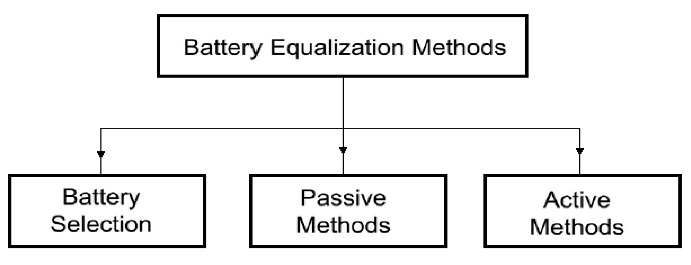
The cell balancing (equalization) methods used in BMS known from the literature [25] can roughly be grouped as follows (see Figure 1):

Figure 1.
Cell balancing methods.
- -
- balancing by parametric selection of cells,
- -
- passive balancing,
- -
- active balancing [26].
Parametric selection (matching) is achieved by choosing cells with very close electrical parameters and electrochemical properties. It is quite an expensive method. Moreover, it does not ensure the maintenance of constant parameters of the cells during operation. The most common practice is, therefore, the passive balancing method. It is based on the dissipation of excess energy of a given cell through its conversion into heat across the appropriately applied resistors. However, since it is an additional source of heat, this method is not recommended for use in mining machines and devices. The requirements of the ATEX directive, particularly concerning the temperature limits of any elements being in contact with the mine atmosphere, are not met [27]. An alternative to the passive method is an active balancing [28]. It can be implemented in several ways. However, they are all based on the principle of energy transfer and distribution between the cells with the use of an appropriate external control system [29]. This reduces the losses associated with the dissipation of energy into heat, provides electricity savings and creates optimal operating conditions for the cells, resulting in extended battery life. Several methods of active balancing are recommended. They depend on the principle of operation and can be grouped differently. Therefore, by taking into account the method of energy transfer, five basic balancing methods can be distinguished, namely: cell bypass, cell to cell, cell to battery pack, pack to cell and cell (s) to pack and to cell (s), as indicated in Figure 2 [30].
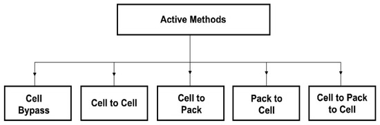
Figure 2.
Classification of the active balancing methods depending on the method of energy transfer.
3. Structure of Developed Active BMS for Mine Suspended Vehicles
The research carried out by the authors shows that there is a real chance for safe and effective use of selected lithium-iron-phosphate batteries to power various mining devices and drives. However, this requires the application of convenient BMS to increase both life and safety, as well as high reliability of operation under mining conditions. It is obvious that the employment of wireless and zero-emission drives can significantly improve the environmental conditions in mines. Therefore, taking into account the expectations of hard coal mines on advanced technical solutions of any drive with reduced weight and increased working safety, the Authors decided to use the selected lithium batteries for a suspended mining vehicle (supporting engine) type PCA-1, as an example. Its structure is shown in Figure 3 and Figure 4. The considered (PCA-1) vehicle is a device used for transporting loads up to around 2 tons at slight inclinations of up to 12° in headings. It moves along the suspended monorail route with the runway profile I 155 at a speed of 1 m/s as can be seen from Figure 3. Its driving force is up to 3.7 kN at the DC powering of 48 V.
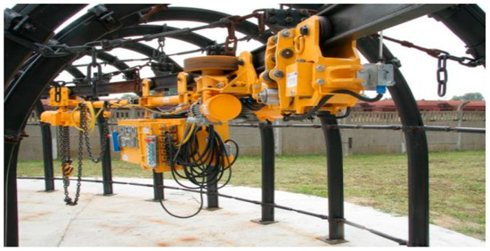
Figure 3.
Operation of a suspended battery vehicle (PCA-1).
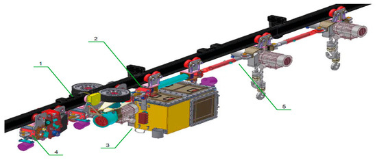
Figure 4.
General view of a suspended battery vehicle (PCA-1) (1—driving trolley; 2—apparatus trolley; 3—power supply module with electrical equipment; 4—brake trolley; 5—transport set).
Because it is extremely difficult to obtain any active BMS on the market, especially for onerous conditions, the authors developed models of two various active BMS structures intended for powering suspended vehicles (PCA-1). The developed active BMS‘s are not expensive (adapted to eight cells in the battery) of a relatively small complexity, however, they are not spark-safe devices. Therefore, together with the cells, they must be placed inside a special metal casing (see 3 in Figure 4) to meet the requirement of the ATEX directive. However, the casing deteriorates the heat exchange with the environment. Therefore, the BMS is exposed to the influence of the same onerous conditions as cells. In general, the offered active BMS solutions, if any, are quite complex and relatively expensive (those that are available are adapted for an increased number of cells). Their complexity and price increases as the number of cells increases. Therefore, the authors limited the considerations to a battery pack consisting of only eight cells connected in series (Figure 5). However, the approach for a much larger number of cells, as well as the conclusions drawn from the research, are not limited to the size of the battery package and its voltage level.
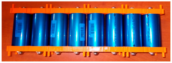
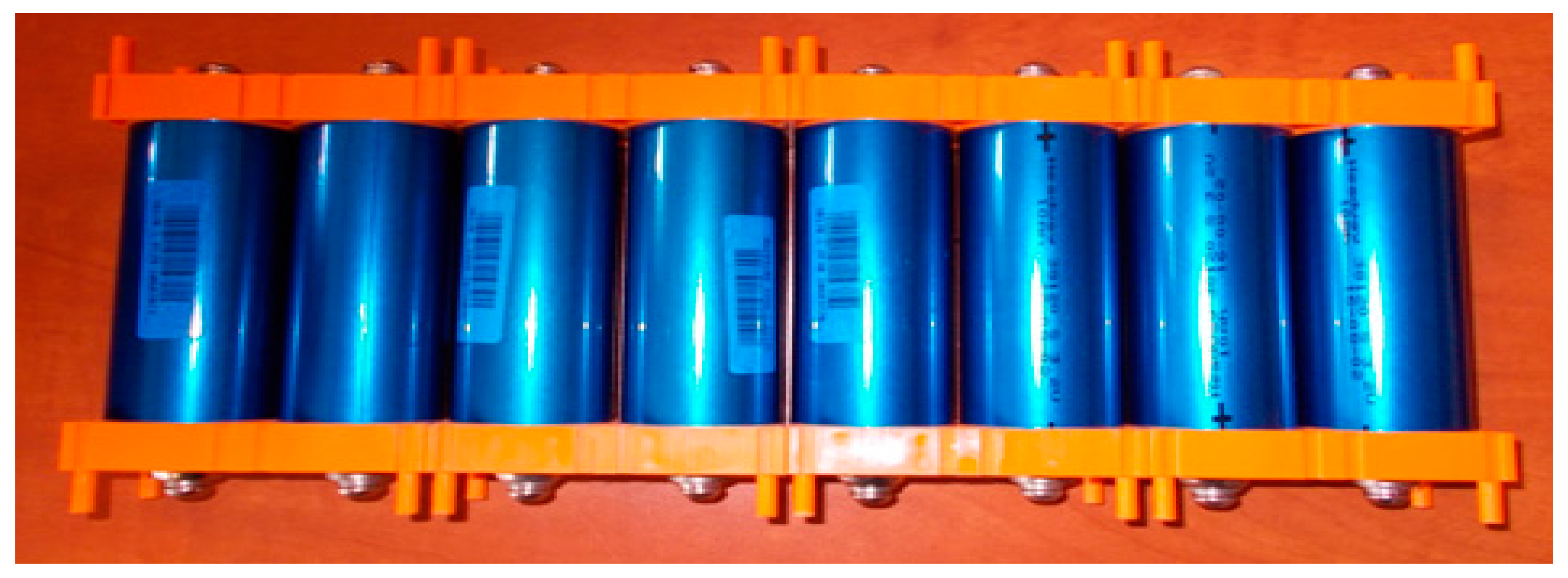
Figure 5.
Battery pack arranged of eight lithium-iron-phosphorous (LiFePO4) cells for testing.
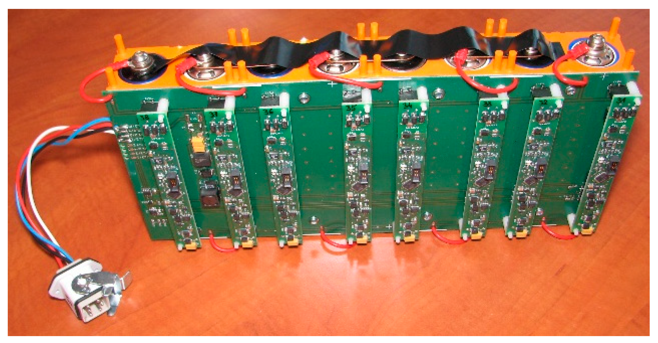
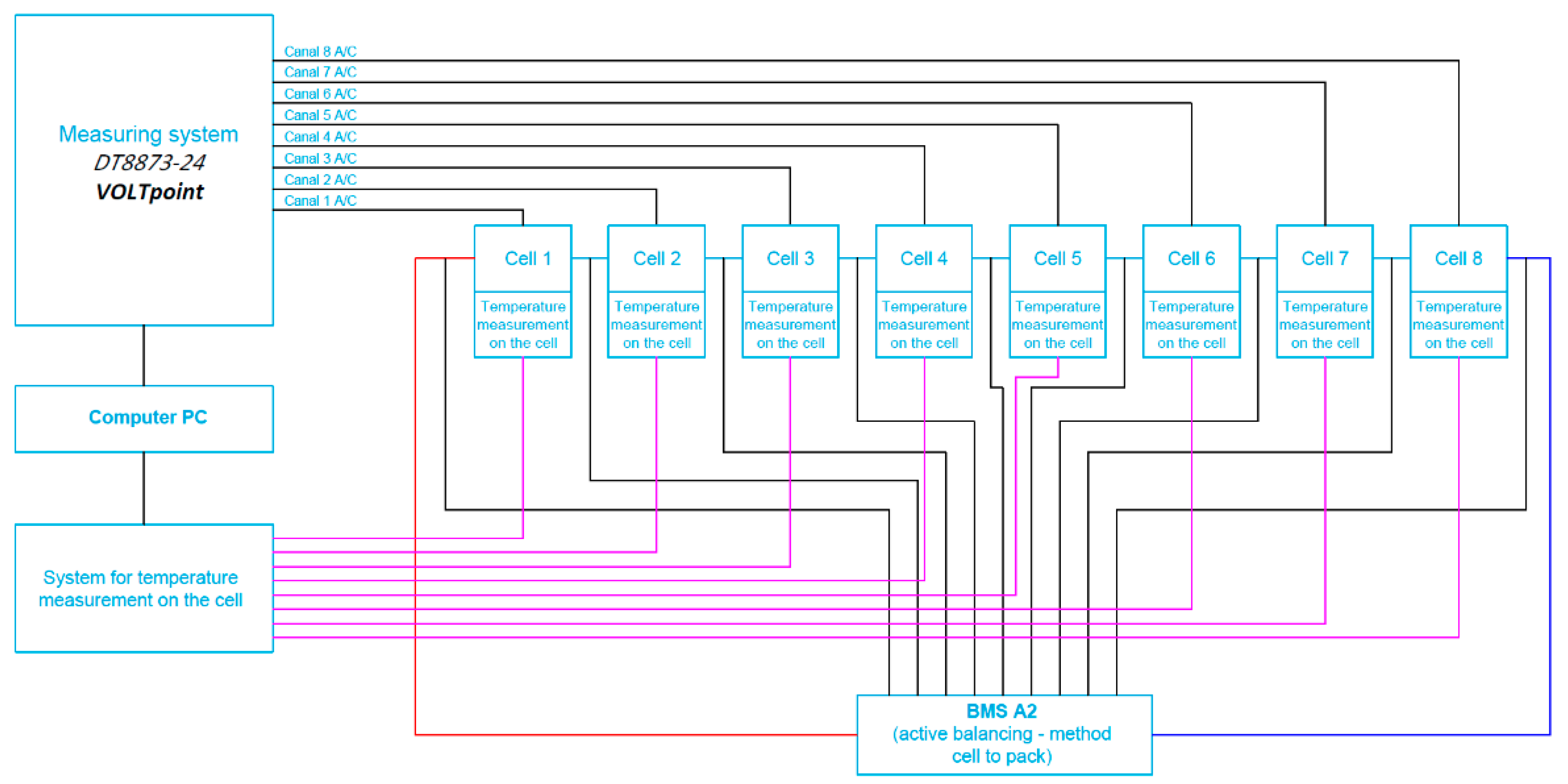
The first of the two active BMS developed at ITG KOMAG uses the cell-to-battery method and is described in detail in the article [31]. Cell balancing in this BMS is carried out by the energy transfer from the most charged cells to the entire battery package. Therefore, the electric charges of the single cells of the battery are equalized. This means that the excess of energy from a single, particular overcharged cell is then provided to the load, for the battery being in a recharging state. However, when the battery is in a charging state, this energy is being returned to the entire package. The view of the BMS installed on the cell package (battery) and the block diagram of the measurement system are shown in Figure 6 and Figure 7.

Figure 6.
View of the active system (cell to battery) BMS installed on the cells package.

Figure 7.
Block diagram of the cell measurement system for the battery with connected BMS with active balancing, the cell-to-battery method.
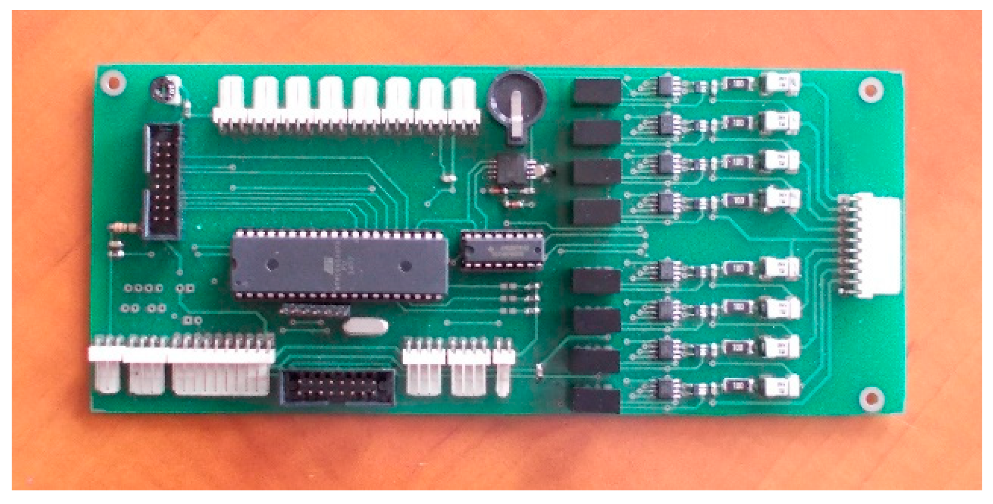
For the second active BMS, developed by ITG KOMAG, the battery-to-cell idea was used. This balancing method is based on the transfer of energy from the entire battery to the “weakest” cell. In this way, the charge of the particular cells of the battery is equalized. The developed BMS is composed of a measurement and control module (Figure 8) and a balancing module (Figure 9). Measurement data are available for reading as well as recording when an SD card is used.

Figure 8.
Measurement and control module.
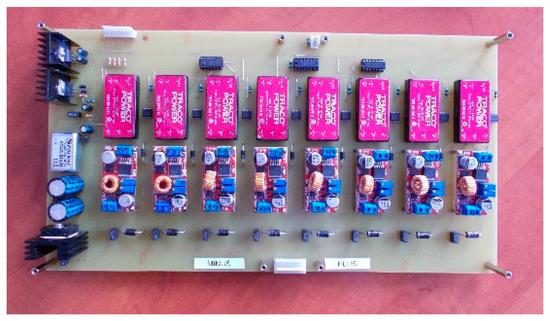
Figure 9.
Active balancer module.
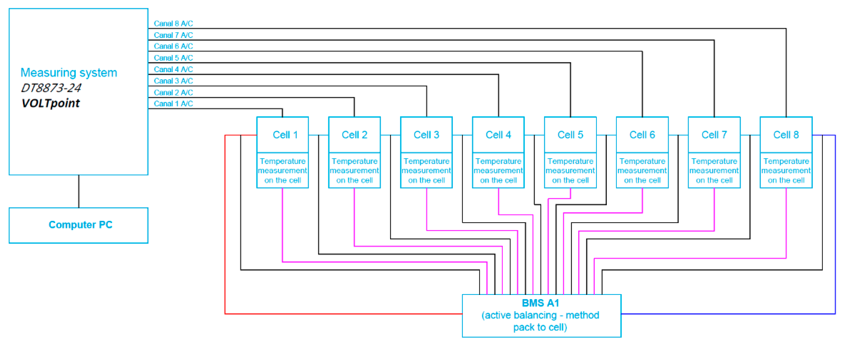
A block diagram of the cell measurement system for the battery with connected BMS with active balancing using the battery to cell method is presented in Figure 10.

Figure 10.
Block diagram of the cell measurement system for the battery with connected BMS with active balancing, the battery-to-cell method.
The evaluation of the work efficiency of the newly developed active BMS also required reference to the passive systems available on the market. Therefore, a suitable passive BMS was selected (for electrical parameters of employed cells) and adapted for comparative studies. Its operation, as already mentioned, is to dissipate excess energy into heat by means of appropriately selected resistors. The block diagram of the measurement system is similar to the BMS with an active balancing, cell-to-battery method (see Figure 7). In this case, the voltage values of particular cells are on-line monitored by the microcontroller with the use of an analog-to-digital converter, to which the cell inputs are connected. If the voltage of one of the cells significantly exceeds value of the others, it is immediately bypassed by a suitable resistor connected to discharge it. Discharging takes until the voltage value of all the cells used in the package equalize. Then the process of charging the battery continues. An example of a passive balancing characteristic for two selected cells is shown in Figure 11.
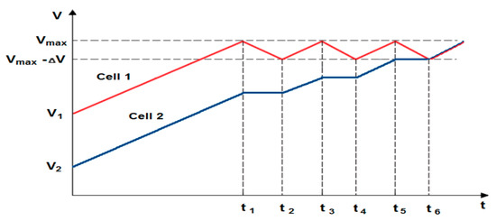
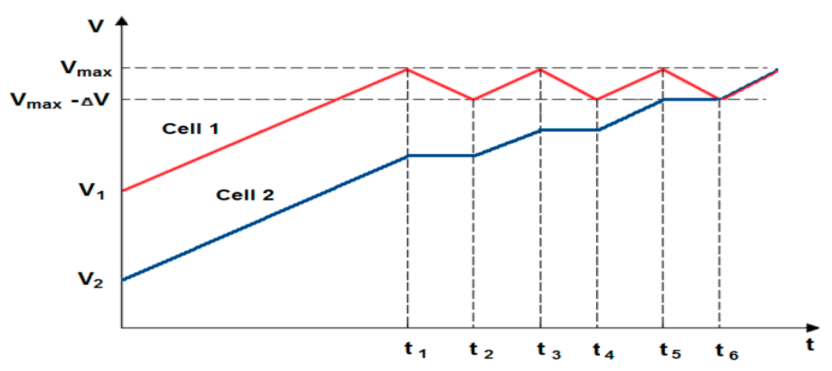
Figure 11.
An example of the characteristics of passive balancing (cell 1—overcharged, cell 2—undercharged; t1–t2, t3–t4, t5–t6—duration of following discharge/charge).
4. The Scope and Way of Testing
The tests were performed for battery packs (consisting of eight LiFePO4, 10 Ah lithium cells, Headway LFP38120 (S) type [28]) operating both under room (about +20 °C, humidity around 40%) and elevated temperature (up to about + 60 °C).
Basic cell technical data [32]:
- ▪
- Voltage: 3.2 V,
- ▪
- Capacity: 10 Ah,
- ▪
- Internal resistance: <6 mOhm,
- ▪
- Charging voltage: 3.65 V ± 0.05 V,
- ▪
- Energy density: 105 Wh/kg,
- ▪
- Technology: lithium-iron-phosphate (LiFePO4),
- ▪
- Maximum discharge voltage: 2.5 V–2.0 V,
- ▪
- Range of operational temperatures:
- ▪
- Charging: 0 ÷ 45 °C,
- ▪
- Discharging: −20 ÷ 65 °C,
- ▪
- Life: over 2000 cycles (80% of capacity when loading with 10A current).
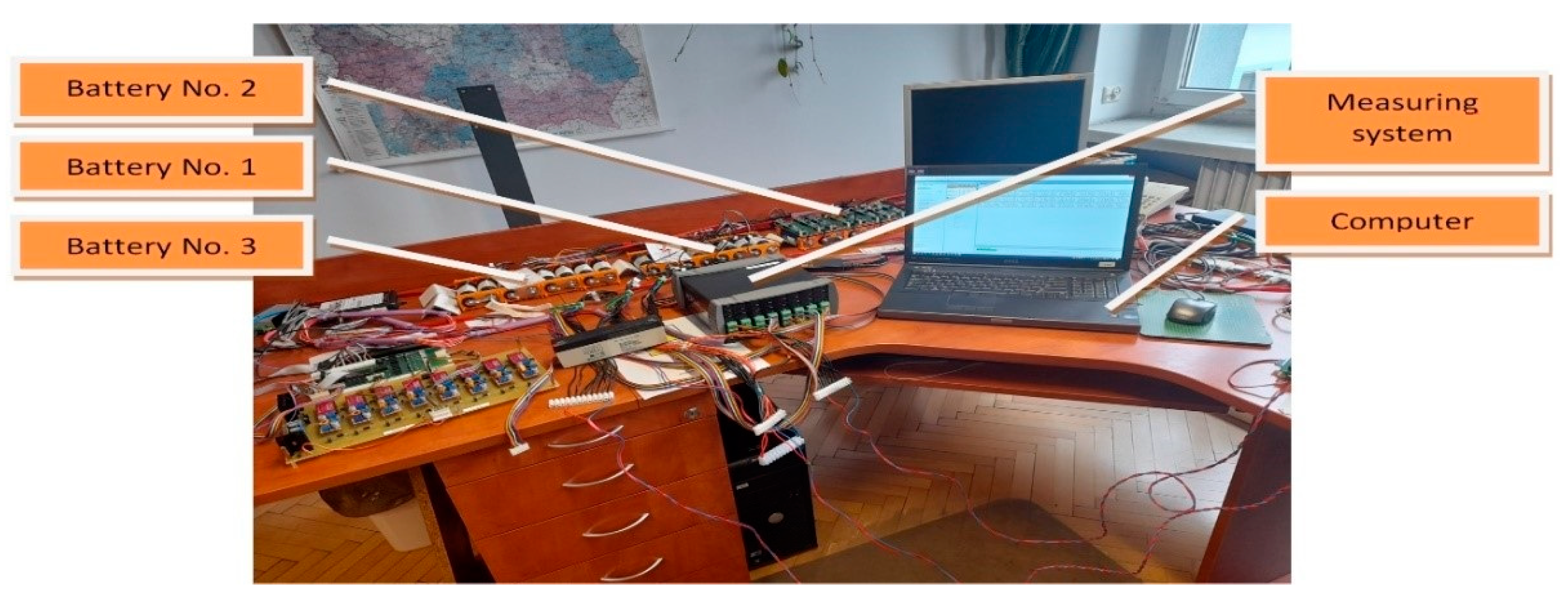
At room temperature, the heat transfer from the battery to the environment was free (Figure 12). However, at different temperature values, the exchange of heat with the environment was deteriorated by the forced test conditions inside the climatic chamber (temperature adjustable in steps from +5 °C to +60 °C at a constant humidity of 75%)—see Figure 13. The stands were equipped with a temperature as well as voltage measurement system (DT8873-24 VOLTpoint) and a computer with specialized software.
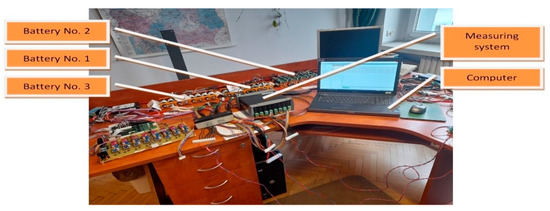
Figure 12.
General view of test stand under room conditions (No. 1—with battery to cell active BMS, No. 2—with cell to battery active BMS, No. 3—with passive BMS).
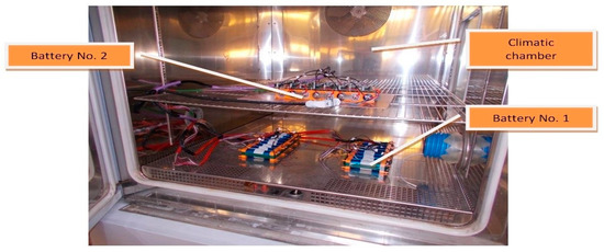
Figure 13.
View of the battery pack arrangement for tests with active BMS in the climatic.
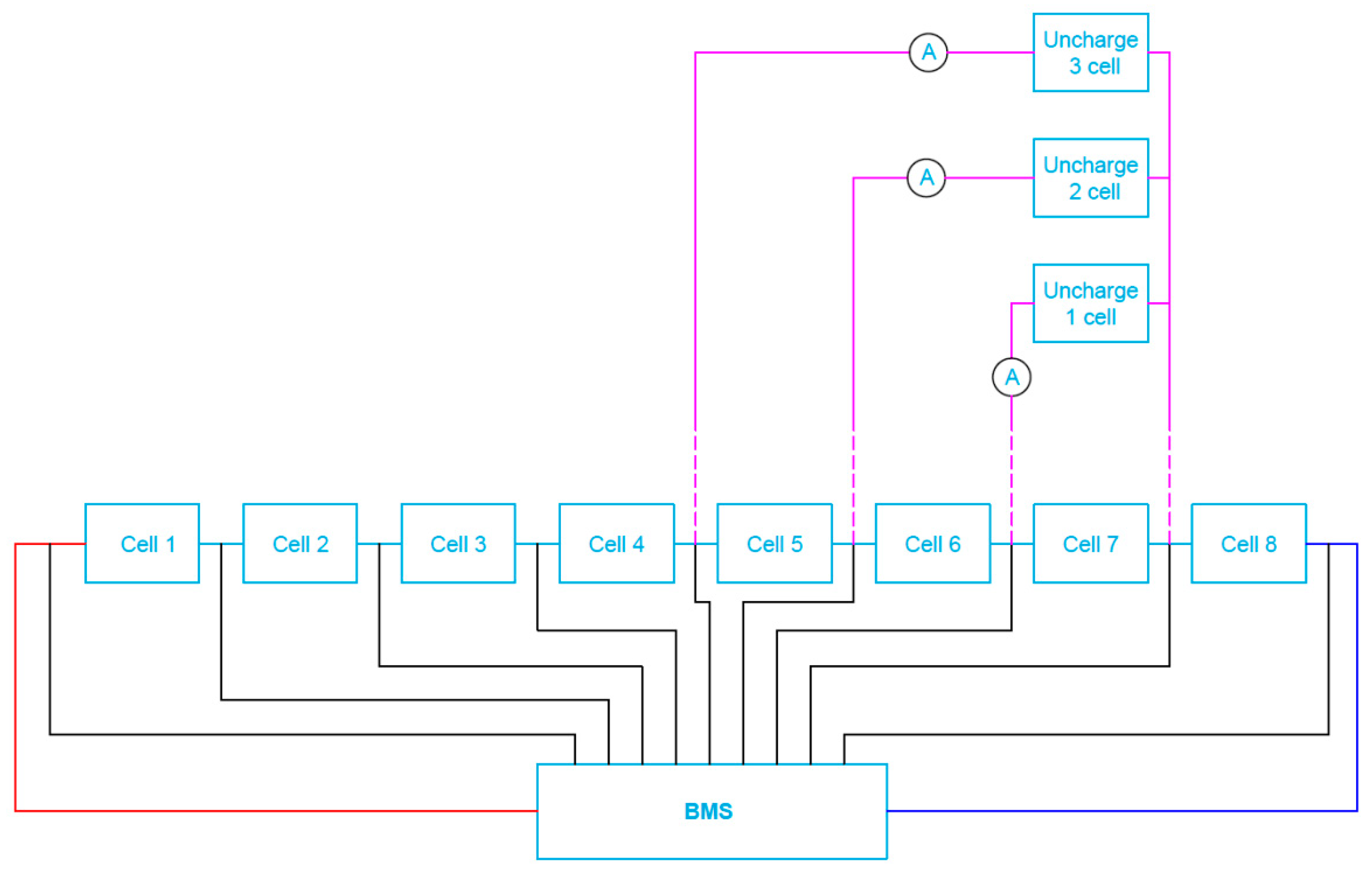
The completed battery packs (unburdened) were next connected to the appropriate active/passive BMS under investigations. However, asymmetry of loading the selected cells (from 1 up to 3 respectively under test) was performed for the discharge current equal to around 25% of the standard discharge value (2.5 A), as shown in Figure 14. Each experiment began for a fully charged battery (voltage of all cells equal to the rated Un = 3.2 V). The 2.5 A current loading lasted until the voltage reached its minimum value Umin (equal to 2.5 V) at the terminals of any of the cells.
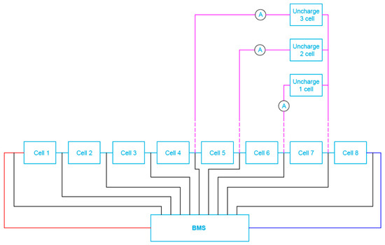
Figure 14.
Block diagram of a cell test system for batteries with connected BMS when simulating one, two and/or three cell load unbalance.
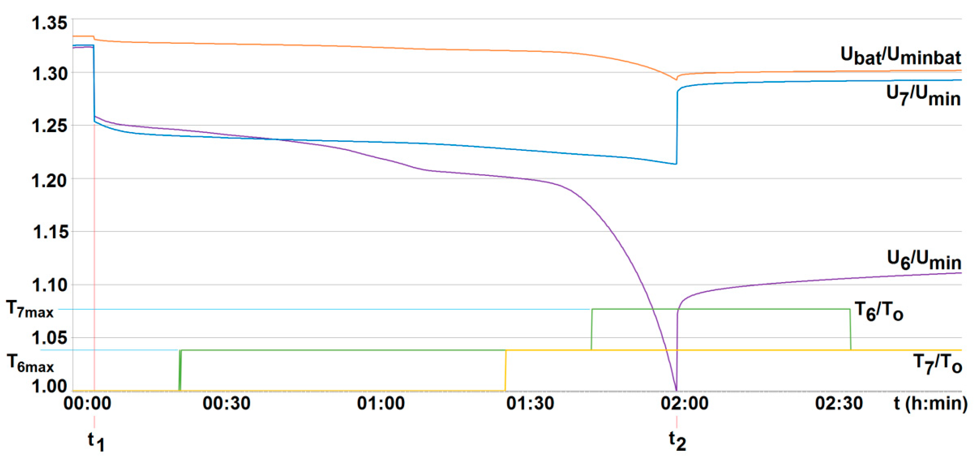
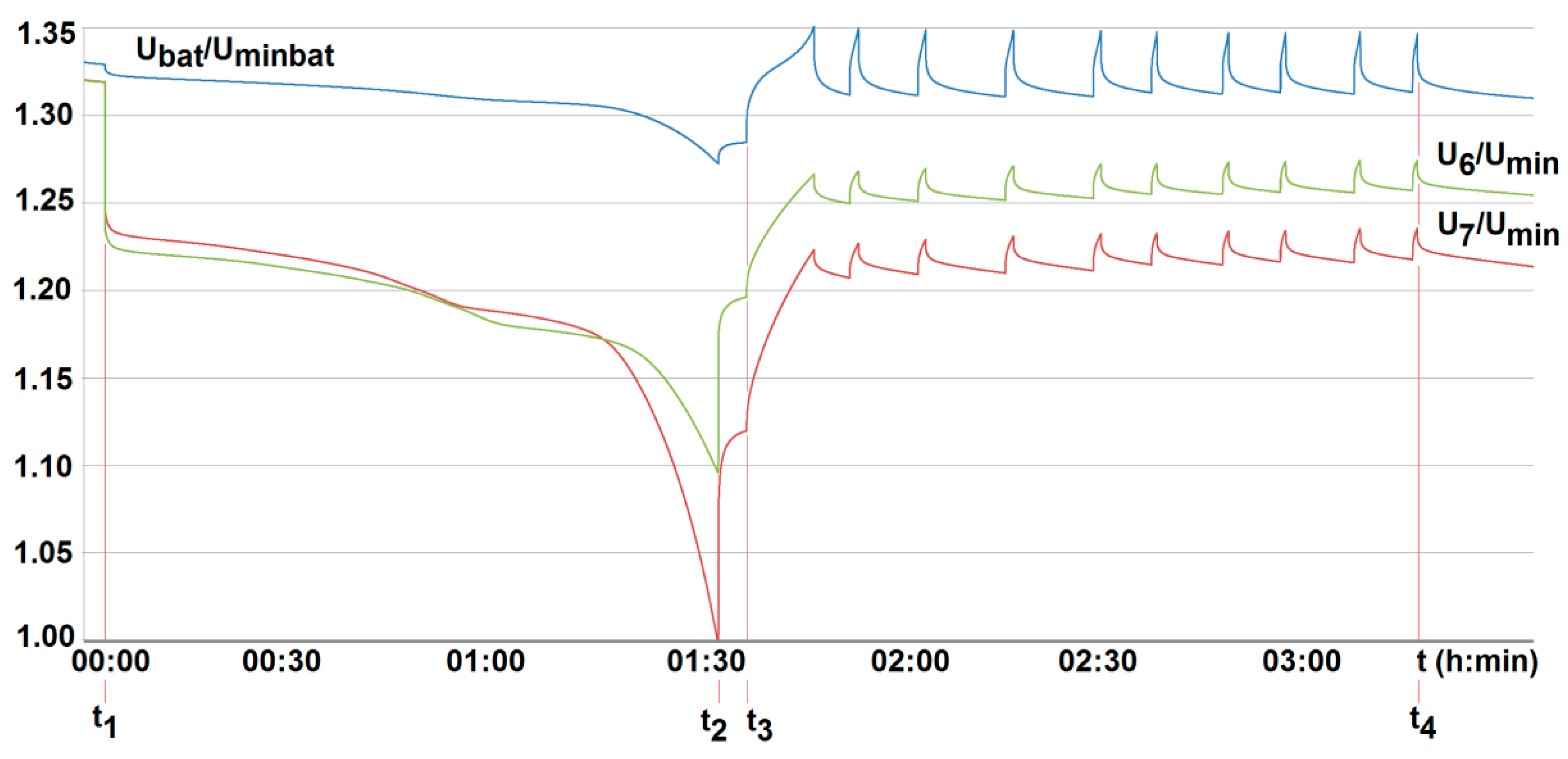
The conducted research indicated that both the particular cell voltage value and its temperature may differ from each other even when loaded (discharged) with the same current value. An example of two selected cells (cell no. 6 and no. 7—see Figure 14) in a battery without the BMS is shown in Figure 15. This justifies the need to control the voltage and temperature of all cells, and therefore the need to use the BMS.
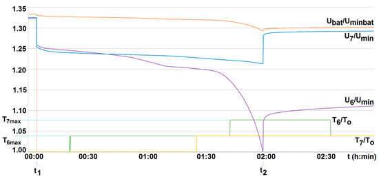
Figure 15.
The voltage U6/Umin and U7/Umin and the temperature T6/T0, T7/T0 variation with time for two series-loaded cells (cells no. 6 and no. 7—see Figure 14) of the unburdened battery without the BMS (room temperature T0 = 20 °C, free cooling, t1, t2—moment of switching on and off the load current of 2.5 A with respective recharging, Umin—minimum cell voltage equal to 2.5 A, Uminbat—minimum battery voltage 20 V, Ubat—battery voltage (maximum 29.2 V).
To compare the performance of the developed active BMS, their technical parameters were properly matched. Therefore, for both active systems, balancing is activated when a cell voltage falls below 3.05 V (U/Un = 0.95). The system is interrupted when it is found to be less than 2.55 V (1.02 Umin) at terminals of all cells employed, and/or when it is less than Umin = 2.5 V, or higher than 3.65 V (U/Un = 1.14) at any of the cells, respectively (see Figure 16 and Figure 17). The balancing current value was fixed to be 2 A (around 40% of a standard charging current). However, for the commercial BMS with passive balancing, the value of the balancing current was set arbitrarily by the manufacturer, amounting to 350 mA. Other technical parameters were able to be specified by configuration using computer software. As a result of the configuration, the passive balancing of cells starts under recharging when the voltage value of the cells is between Un = 3.2 V and 3.65 V (1.14 Un), but is turned off when the voltage at the terminals of any of the cells is less than Umin = 2.5 V and/or is over 1.14Un (3.65 V), respectively (see Figure 18).
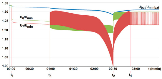
Figure 16.
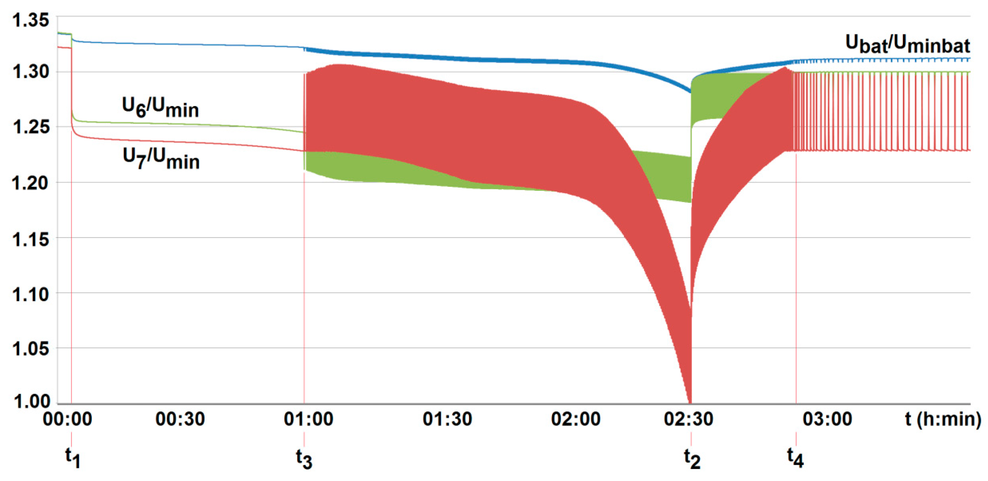
The voltage U6/Umin and U7/Umin variation with time for two series-loaded cells (cells no. 6 and no. 7—see Figure 14) of the unburdened battery with the BMS using the battery-to-cell method (room temperature T0 = 20 °C, free cooling, t1, t2—moment of switching on and off the load current of 2.5 A, Umin—minimum cell voltage equal to 2.5 A, Uminbat—minimum battery voltage 20 V, Ubat—battery voltage (maximum 29.2 V), t3, t4—switching on and off the active balancing.
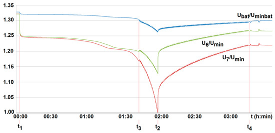
Figure 17.
The voltage U6/Umin and U7/Umin variation with time for two series-loaded cells (cells no. 6 and no. 7—see Figure 14) of the unburdened battery with the BMS using the battery-to-cell method (room temperature T0 = 20 °C, free cooling, t1, t2—moment of switching on and off the load current of 2.5 A, Umin—minimum cell voltage equal to 2.5 A, Uminbat—minimum battery voltage 20 V, Ubat—battery voltage (maximum 29.2 V), t3, t4—switching on and off the active balancing.
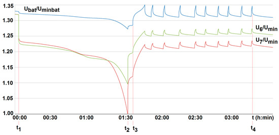
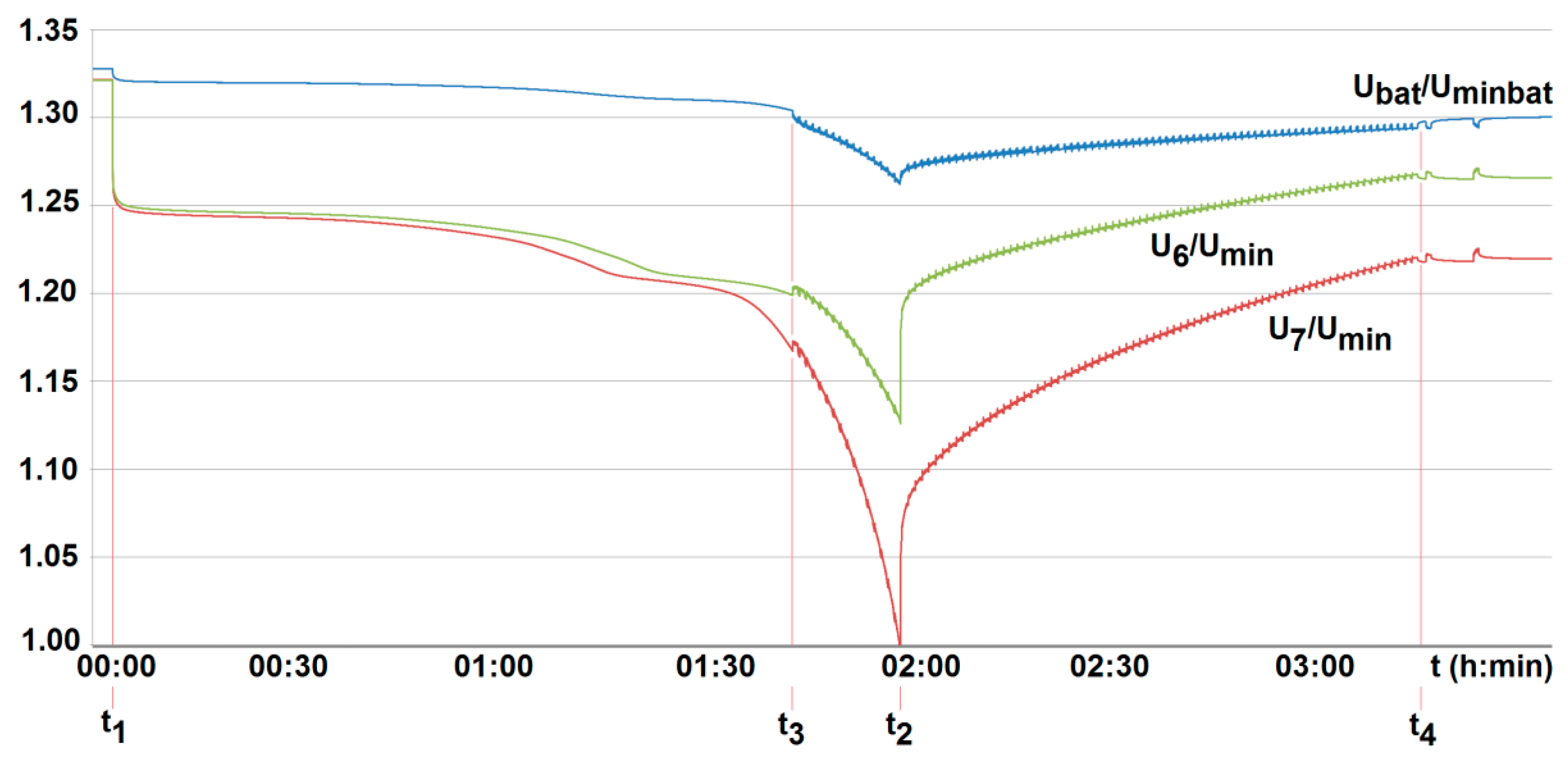
Figure 18.
The voltage U6/Umin and U7/Umin variation with time for two series-loaded cells (cells no. 6 and no. 7—see Figure 14) of the unburdened battery with the BMS using the battery-to-cell method (room temperature T0 = 20 °C, free cooling, t1, t2—moment of switching on and off the load current of 2.5 A, Umin—minimum cell voltage equal to 2.5 A, Uminbat—minimum battery voltage 20 V, Ubat—battery voltage (maximum 29.2 V), t3, t4—switching on and off the passive balancing.
The differences in the voltage graphs seen in Figure 16, Figure 17 and Figure 18 result only from the mode of measuring and recording the data. However, this does not affect in any way the accuracy of the measurement and the evaluation of the analyzed balancing effect.
The tests were carried out for three battery packs, each composed of eight cells of the same type. They separately worked with one passive and two active BMS applied. Each measurement of both temperature and cell voltage was repeated five times, thus calculating the mean values with a confidence level of 0.95 using the Student’s t-test [33].
5. Results and Discussion
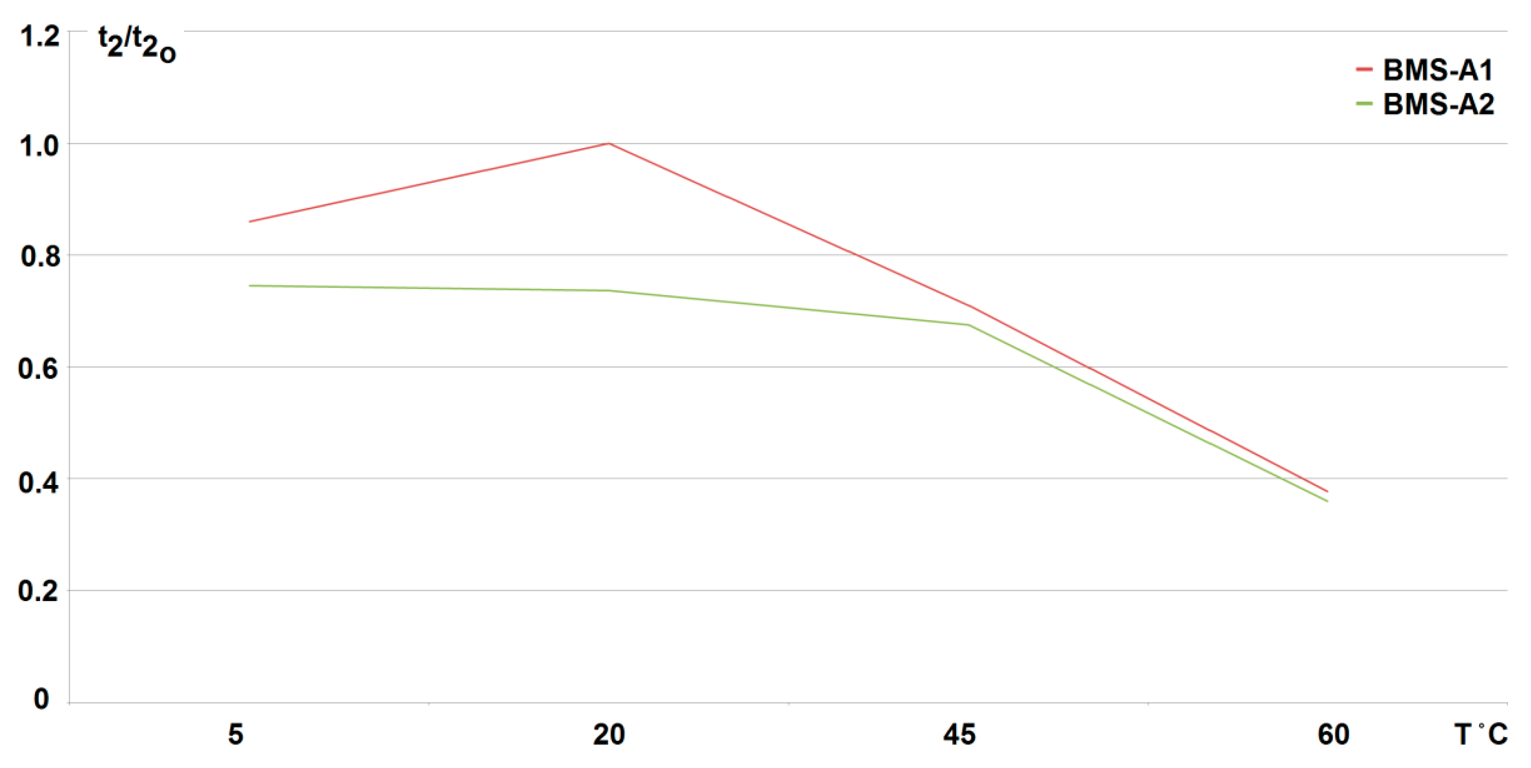
The conducted research shows that the use of any developed active balancing system (active BMS) extends the duration of the fading (discharge time of the cells to the minimum voltage value Umin = 2.5 V). Therefore, it increases the battery life respectively. For the cell-to-battery method, it is increased by more than 30%, and for the battery-to-cell method by more than 70%, for two loaded (discharged) cells at 20 °C (what can be compared from Figure 15, Figure 16 and Figure 17). As the number of loaded (discharged) cells increases (provided it is no more than 50%) this effect becomes more visible. However, for a passive method, the cells are recharged only after the load is turned off and the battery recharging process begins (see Figure 18). So, it was found that the best results were achieved at room temperature (20 °C) when using the active BMS based on the battery-to-cell method (indicated as BMS-A1). When increasing the discharge current as well as the number of cells, the duration of fading (discharge) decreases linearly with the increase in the temperature value. For two cells being discharged (25% of total cell number) with a current increased to 38% of the standard discharge value (3.8 A), the dependence of fading time t2 on temperature is shown in Figure 19. It should be noted that although the influence of the ambient temperature significantly shortens the discharge time, it does not cause an excessive increase in the cell temperature. During the discharge and following balancing of the loaded cells, the difference in their temperature before and after the test did not increase by more than by about 4 °C.
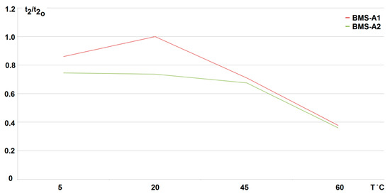
Figure 19.
Variation in fading time t2 of cell voltage to its minimum value (U = 2.5 V) with ambient temperature T when use active BMS (BMS-A1-battery to cell method, BMS-A2-cell to battery); reference time for 20 °C equal t20 = 114 min for BMS-A1).
Because it is extremely difficult to obtain any active BMS on the market, the conducted temperature research has indicated that a system with active balancing by the battery-to-cell method (BMS-A1) seems to be the most advantageous. It keeps the voltage above the minimum value at the discharged cell/cells for the longest time. This situation is beneficial since it extends the life of the battery without interrupting its operation for the time of charging. However, the use of other active methods (BMS-A2) based on the cell-to-battery exchange also allowed for longer maintenance of the cell/cells voltage, but only when compared with the passive balancing. Note that when comparing the data in Figure 19, it is necessary to take into account the shorter (by about 30%) time t20 (at 20 °C) for the battery pack with the active system BMS-A2 employed.
6. Conclusions
- -
- To ensure long-term, reliable, and safe operation of lithium-iron-phosphate cells under onerous mining environments, the on-line control of their parameters under work needs to be performed. This applies, of course, firstly to both temperature and voltage. This is due to limited cooling conditions and high thermal inertia of cells. As a result, their temperature may reach significant and unacceptable values, not only during deep discharge. This may occur for example, during short lasting but frequently and randomly repeated in time (manufacturer-permitted) pulse discharge currents.
- -
- The conducted tests have also shown that particular cells of the same type behave differently, even when loaded with the same current value. They display different values of temperature and time of voltage(power) fading. Moreover, the difference in parameters of individual cells may change during operation. For this reason, their balancing is also needed. Therefore, the lithium-iron-phosphate cell may be used to power selected suspended battery vehicles, providing BMS is applied.
- -
- There are many different types of BMS systems available on the market, especially passive solutions intended mainly for electric vehicles. However, their use in mining conditions is a problem, due to the undesirable effect of heat dissipation on the equalizing resistors. Therefore, the value of balancing currents must be limited. This results in an unfavorable extension of the cell balancing times, which significantly deteriorates the performance of the device supplied. Therefore, the most advantageous and safest way to power mining equipment is to use active BMS systems appropriately selected and adapted to a particular application.
- -
- The obtained results of tests carried out for two active BMS, developed by the authors and intended to power the suspended mining vehicle, show that the battery-to-cell method is the most useful. For example, the duration of the voltage fad (i.e., the respective lifetime) increased by more than 70% compared to operation without BMS, for 25% of loaded cells. As the number of loaded (discharged) cells increases (provided it is no more than 50%), this effect becomes more visible. It should be noted that although the influence of the ambient temperature significantly shortens the discharge time, it does not cause an excessive increase in the cell temperature. As a result of investigations, the usefulness of the developed active BMS in practice was determined, enabling the extension of the lithium-iron-phosphate battery life for a single recharge under the onerous mine environment, which is a novelty.
Author Contributions
Conceptualization, W.K. and B.P.; methodology, W.K. and M.S.; software, P.F.-G. and P.D.; validation, M.H., and B.M.; investigation, W.K. and B.P.; resources, G.D. and M.Z.; writing—original draft preparation, W.K., B.M., and B.P.; visualization, W.K., M.Z. and M.H. All authors have read and agreed to the published version of the manuscript.
Funding
The paper received no external funding.
Institutional Review Board Statement
Not applicable.
Informed Consent Statement
Not applicable.
Data Availability Statement
Not applicable.
Conflicts of Interest
The authors declare no conflict of interest.
References
- Radchenko, D.; Bondarenko, A. Mining engineering system as an energy asset in industry 4.0. In Proceedings of the Rudenko International Conference Methodological Problems in Reliability Study of Large Energy Systems (RSES 2018), Funchal, Madeira Island, Portugal, 24–26 October 2018; EDP Sciences: Les Ulis, France, 2018; Volume 58, p. 01009. [Google Scholar]
- Kałuża, E.; Piksa, P.; Setlak, R. Wyznaczanie parametrów energetycznych kwasowych ogniw trakcyjnych stosowanych w lokomotywach dołowych. Wiadomości Elektrotechniczne 2005, 12, 47–49. [Google Scholar]
- Pemberton, J.C. Underground transportation of men and materials in Australian coal mines. Colliery Guard. 1982, 230, S12–S14. [Google Scholar]
- Świątek, J. Ewolucja technologii akumulatorów kwasowo-ołowiowych. Energetyka 2000, 4, 154–158. [Google Scholar]
- Ma, L.; Chen, Q. Problems and research on underground charging safety of power battery for coal mine robot. In Proceedings of the 3rd International Conference on Green Energy and Sustainable Development, Shenyang, China, 14–15 November 2020; IOP Publishing: Bristol, UK, 2020; Volume 651, p. 032100. [Google Scholar]
- Polnik, B. Jakość energii elektrycznej napędów górniczych lokomotyw akumulatorowych w aspekcie emisji gazu elektrolitycznego. Masz. Elektr. Zesz. Probl. 2015, 106, 73–78. [Google Scholar]
- Reyes, M.A.; Novak, T. Injury surveillance and safety considerations for large-format lead-acid batteries used in mining applications. IEEE Trans. Ind. Appl. 2015, 52, 1925–1930. [Google Scholar] [CrossRef] [PubMed] [Green Version]
- Barsukov, Y. Battery Cell Balancing: What to Balance and How; Texas Instruments, Inc.: Dallas, TX, USA, 2005. [Google Scholar]
- Semykina, I.; Zavyalov, V.; Dubkov, E.; Veliliaev, A.H. On the possibility of wireless battery charging in a gaseous-and-dusty mine. In Proceedings of the 10th Anniversary Russian-Chinese Symposium Clean Coal Technologies: Mining, Processing, Safety, and Ecology, Kemerovo, Russia, 19–21 October 2021; EDP Sciences: Les Ulis, France, 2021; Volume 303, p. 01032. [Google Scholar]
- Cao, J.; Schofield, N.; Emadi, A. Battery Balancing Methods: A Comprehensive Review. In Proceedings of the IEEE Vehicle Power and Propulsion Conference, VPPC, Harbin, China, 3–5 September 2008. [Google Scholar]
- Kurpiel, W.; Polnik, B.; Miedziński, B. System nadzorujący pracę baterii akumulatorów (BMS) w celu zwiększenia bezpieczeństwa ich funkcjonowania i żywotności stosowanych ogniw. Mech. I Autom. Górnictwa 2014, 5, 47–49. [Google Scholar]
- Kurpiel, W.; Polnik, B.; Miedziński, B. Właściwości eksploatacyjne ogniw litowych. Elektro Info 2018, 10, 44–48. [Google Scholar]
- Lisbona, D.; Snee, T. A review of hazards associated with primary lithium and lithium-ion batteries. Process. Saf. Environ. Prot. 2011, 89, 434–442. [Google Scholar] [CrossRef]
- Moore, S.W.; Schneider, P.J. A Review of Cell Equalization Methods for Lithium Ion and Lithium Polymer Battery Systems; Technical Paper 2001-01-0959; SAE International: Warrendale, PA, USA, 2001; p. 7. [Google Scholar]
- Wen, S. Cell Balancing Buys Extra Run Time and Battery Life; Texas Instruments, Inc.: Dallas, TX, USA, 2009. [Google Scholar]
- Ziegler, A.; Oeser, D.; Arndt, B.; Ackva, A. Comparison of Active and Passive Balancing by a Long Term Test Including a Post-Mortem Analysis of all Single Battery Cells. In Proceedings of the 2018 International IEEE Conference and Workshop in Óbuda on Electrical and Power Engineering (CANDO-EPE), Budapest, Hungary, 20–21 November 2018; pp. 000015–000020. [Google Scholar]
- Xiong, R.; Li, L.; Tian, J. Towards a smarter battery management system: A critical review on battery state of health monitoring methods. J. Power Sources 2018, 405, 18–29. [Google Scholar] [CrossRef]
- Xiong, R.; Ma, S.; Li, H.; Sun, F.; Li, J. Toward a safer battery management system: A critical review on diagnosis and prognosis of battery short circuit. Iscience 2020, 23, 101010. [Google Scholar] [CrossRef]
- Lipu, M.H.; Hannan, M.A.; Karim, T.F.; Hussain, A.; Saad, M.H.; Ayob, A.; Miah, M.S.; Mahlia, T.I. Intelligent algorithms and control strategies for battery management system in electric vehicles: Progress, challenges and future outlook. J. Clean. Prod. 2021, 292, 126044. [Google Scholar] [CrossRef]
- Carkhuff, B.G.; Demirev, P.A.; Srinivasan, R. Impedance-based battery management system for safety monitoring of lithium-ion batteries. IEEE Trans. Ind. Electron. 2018, 65, 6497–6504. [Google Scholar] [CrossRef]
- Frost, D.F.; Howey, D.A. Completely decentralized active balancing battery management system. IEEE Trans. Power Electron. 2017, 33, 729–738. [Google Scholar] [CrossRef]
- Xu, J.; Li, S.; Mi, C.; Chen, Z.; Cao, B. SOC Based Battery Cell Balancing with a Novel Topology and Reduced Component Count. Energies 2013, 6, 2726–2740. [Google Scholar] [CrossRef] [Green Version]
- Lee, J.; Kim, J.M.; Yi, J.; Won, C.Y. Battery Management System Algorithm for Energy Storage Systems Considering Battery Efficiency. Electronics 2021, 10, 1859. [Google Scholar] [CrossRef]
- Perişoară, L.A.; Guran, I.C.; Costache, D.C. A passive battery management system for fast balancing of four LiFePO4 cells. In Proceedings of the 2018 IEEE 24th International Symposium for Design and Technology in Electronic Packaging (SIITME), Iasi, Romania, 25–28 October 2018; IEEE: Piscataway, NJ, USA, 2018. [Google Scholar]
- Daowd, M.; Omar, N.; Van Den Bossche, P.; Van Mierlo, J. Passive and Active Battery Balancing comparison based on MATLAB Simulation. In Proceedings of the 7th IEEE Vehicle Power and Propulsion Conference, VPPC’11, Chicago, IL, USA, 6–9 September 2011. [Google Scholar]
- Lukasiewycz, M.; Kauer, M.; Steinhorst, S. Synthesis of Active Cell Balancing Architectures for Battery Packs. IEEE Trans. Comput. Aided Des. Integr. Circuits Syst. 2016, 35, 1876–1889. [Google Scholar] [CrossRef]
- EN 60079-1:2014/AC:2018-09. Explosive Atmospheres—Part 1: Equipment Protection by Flameproof Enclosures “d”. Available online: https://standards.iteh.ai/catalog/standards/clc/e87e6b2c-cf55-4187-aeb3-eb0490b0bdfe/en-60079-1-2014 (accessed on 17 August 2021).
- Diao, W.; Xue, N.; Bhattacharjee, V.; Jiang, J.; Karabasoglu, O.; Pecht, M. Active battery cell equalization based on residual available energy maximization. Appl. Energy 2018, 210, 690–698. [Google Scholar] [CrossRef]
- Zheng, X.; Liu, X.; He, Y.; Zeng, G. Active vehicle battery equalization scheme in the condition of constant-voltage/current charging and discharging. IEEE Trans. Veh. Technol. 2017, 12, 47–49. [Google Scholar]
- Shah, S.; Murali, M.; Gandhi, P. A Practical Approach of Active Cell Balancing in a Battery Management System. In Proceedings of the IEEE International Conference on Power Electronics, Drives and Energy Systems (PEDES), Chennai, India, 18–21 December 2018; pp. 1–6. [Google Scholar]
- Jura, J.; Bartoszek, S. Układ aktywnego balansowania baterii ogniw litowych przeznaczony do górniczych maszyn mobilnych. Masz. Górnicze 2019, 1, 52–65. [Google Scholar]
- Documentation of Battery LiFePO4 3.2 V. Available online: https://www.bto.pl/produkt/31801/headway-lfp38120(s)-10000mah-lifepo4 (accessed on 10 August 2021).
- Taylor, R.J. Introduction to Error Analysis, the Study of Uncertainties in Physical Measurements, 2nd ed.; University Science Books: Sausalito, CA, USA, 1997. [Google Scholar]


Publisher’s Note: MDPI stays neutral with regard to jurisdictional claims in published maps and institutional affiliations. |
© 2021 by the authors. Licensee MDPI, Basel, Switzerland. This article is an open access article distributed under the terms and conditions of the Creative Commons Attribution (CC BY) license (https://creativecommons.org/licenses/by/4.0/).