Article

Using Sine Function-Based Nonlinear Feedback to Control Water Tank Level

Navigation College, Dalian Maritime University, Dalian 116026, China
*
Author to whom correspondence should be addressed.
Energies 2021, 14(22), 7602; https://doi.org/10.3390/en14227602
Submission received: 4 October 2021 / Revised: 2 November 2021 / Accepted: 11 November 2021 / Published: 13 November 2021

Abstract

:
This manuscript addresses the feasibility and significance of using a sine function to modify the system error of a normal linear feedback control to achieve more efficient capabilities in terms of energy-saving. The associated mathematic modeling and assessment were demonstrated by presenting a case analysis on the capabilities of controlling water level for a single tank. The principle of robust control and the theories and detailed algorithm of Lyapunov stability were applied to assess the result derived by novel nonlinear feedback in the form of sine function for optimizing the robustness of the PID (Proportional–Integral–Derivative) controller and economizing energy. Two control simulations are compared: nonlinear feedback control using a sine function and conventional fuzzy control. The results reveal that using the nonlinear feedback controller, a reduction of up to 32.9% of the average controlled quantity is achieved, and the performance index is improved by 24.0% with satisfactory robustness. The proposed nonlinear feedback control using a sine function provides simplicity, convenient implementation, and energy efficiency.

1. Introduction

Traditionally, the three major objectives in the automatic control field have been pursuing sound performance on stability, precision, and speed for years. With advances in control algorithms and design, increasing effort has been directed at promoting energy savings, low cost, and simplicity [1]. Considering the increased complexity and uncertainty of control systems, nonlinear characteristics are increasingly used in designing controllers. However, the conventional PID controller, which has advantages in terms of simplicity, reliability, and physical significance, remains widely implemented in the industrial field. The shortcomings existing in the conventional PID control would be resolved if the control quantity and deviation signals could be feasibly interrelated by means of nonlinear feedback PID control. Contemporarily, nonlinear feedback control which is a kind of novel theory will be potentially developed driven by the demand of upgrading the control performance that control domain desires. The philosophy that nonlinear feedback control advocates is to modify the error signal by means of nonlinear prior to sending back to the original controller. The controller itself remains unchanged but the error signal has been nonlinearly verified, to consume less energy but achieve the same outcome as original one does. This is the promising merit that nonlinear feedback control owns.
Controlling water level in a single tank has been regarded as a typical example in the control field and frequently studied as a benchmark to evaluate the control performance of a new algorithm. As far as shipping industry is concerned, the adhibition of water level control is essential for providing better service and sound working conditions. For instances, there are several tanks fitted onboard of ships for containing different fluids which would be served for the intended voyage, namely heavy fuel tanks, diesel oil tanks, tanks for ballast water and freshwater, etc. Considering the daily consumption, stability adjustment and sea condition, etc., the way of controlling liquid level is of importance in terms of safety at sea. Many existing studies regarding the level control onboard a ship were mostly conducted from the application of conventional PID control. Nevertheless, such control method might be hindered in further development due primarily to the complicated control law, difficulties of determining parameters, and inefficiency of energy-saving. A control design that saves energy would therefore be advantageous with respect to the worldwide green shipping campaign.
Control theory has undergone three successive stages: classical control, modern control, and postmodern control (also known as robust control) [2]. In recent decades, nonlinear control research has become a mainstream approach in the domain of control theory. The principle of nonlinear feedback involves constructing state feedback or output feedback through nonlinear elements to achieve superior performance to that of linear feedback. In addition, nonlinear control often has other purposes, such as simplification of the control system structure, analysis, and design methods to achieve expected performance [3]. A feedback control system is the fundamental control mode in an automatic control system. Conventional error feedback is achieved by linear feedback control whose control mode is the most widely used. However, in recent decades, control algorithms for designing a controller have gradually changed from linear control to nonlinear control considering improving the accuracy of the control system.
Research on water tank level control and related experiments involve knowledge of process control. Both linear and nonlinear tanks can be used as examples to highlight relevant knowledge [4,5]. Historically, fuzzy systems have been widely used in many sectors of the industry, and researchers have created various mathematical models and control modes of fuzzy control systems for use in liquid level control [6,7,8]. As nonlinear control emerged in the control field over the past two decades, the focus of controlling a water tank level shifted from a linear to nonlinear perspective, and various algorithms and models have been proposed. Robust nonlinear control using finite-time disturbance observers has been proposed for a three-tank system with the purpose of tracking mismatched output [9]. Dynamic matrix predictive control has also been proposed, and associated simulations have been performed to analyze various control modes for water tanks to compare their effectiveness with that of traditional PID control [10]. Similarly, in [11], the authors proposed a type of nonlinear control of a two-tank hybrid system by applying a sliding mode controller in relation to a fractional-order PID. Furthermore, ref. [12] put forward the mathematic modeling derived by two basic nonlinear differential equations to concentrate on the adaptive control of a nonlinear system.
A novel mathematical model using a bee algorithm was also proposed to control a nonlinear system for the purpose of solving open-loop optimization problems [13]. PLC-based (Programmable Logic Controller) fractional-order controller design was also investigated for the evaluation of robustness and stability of fractional-order discrete PID feedback loops for varying methods and orders [14]. In addition, in [15], the authors studied the problem for controlling water level in a tank and examined controllers in terms of both fractional-order proportional integral and fractional-order proportional–derivative with respect to outer and inner loops to check performance, as far as energy efficiency is concerned. Controller which is designed with nonlinear robust has been largely applied in the marine transportation fields. In [16], the authors formulated a simple controller and fixed parameters for verifying the control performance and robustness using a simulation test for a MASS (Maritime Autonomous Surface Ship) ship.
Zhang and Zhang XK presented backstepping control designed by a nonlinear algorithm for constructing a course-keeping controller for vessels [17]. Similarly, in [18], the authors proposed algorithm for a robust adaptive fuzzy neural network control and created a PID controller for the heading control of UMV (Unmanned Marine Vehicles). Many other nonlinear control models have been proposed and evaluated to establish mathematical models from different perspectives [19,20,21,22]. However, in terms of energy-saving performance, additional research is required.
Based on the above observations, this paper presents a sine function-based nonlinear feedback controller and performs an evaluation regarding water level control in a tank. Having reviewed the existing study, the prominent contributions of this work are: (i) a novel control algorithm and models decorated by sine function-based nonlinear are mathematically proved, and associated nonlinear feedback controller is formulated for controlling the water level; (ii) the energy-saving capability is further enhanced by lessening the amplitude of control input.
The remainder of the paper is outlined in accordance with the following sections. Relevant mathematic modeling, interrelated algorithms, and the controller design were presented in Section 2. Stability and demonstration were both analytically and mathematically carried out in Section 3 based on Young’s inequality and Lyapunov stability theory etc. Section 4 mainly illustrated the assessments of capabilities for controlling the water level by means of simulation under various scenarios. The simulation results were concluded, and future work were anticipated in the last section.

2. Mathematical Model and Related Algorithms

A representative PID controller owns the characteristics of simplicity, dependability, and prominent physical significance. Conventional PID control has steadily advanced into numerous modified modes, for instances, self-adaptive PID control, gain scheduling PID control, self-tuning PID control, and robustness PID control, etc., with the aim of lessening the inadequacies of conventional PID control. These inadequacies mainly reflect on the integration of parameters, weak self-adaptive ability, restricted robustness, and poor control accuracy [23,24].

2.1. Mathematic Modeling and Determination of PID Parameters

Control object G(s) is defined with its coefficient as a second-order strictly proper plant as follows:
G ( s ) = b 0 a 2 s 2 + a 1 s + 1
Accordingly, by applying a closed-loop gain algorithm, a robust PID controller can be expressed as follows:
K ( s ) = a 2 s 2 + a 1 s + a 0 b 0 T 1 s = a 1 b 0 T 1 + a 0 b 0 T 1 s + a 2 s b 0 T 1
Equation (2) is a standard PID controller, and its parameters are
K p = a 1 b 0 T 1 , K i = a 0 b 0 T 1 , K d = a 2 b 0 T 1
where 1/T1 is deemed as bandwidth frequency of the system.

2.2. Adhibition of Robust PID Control: Case Study of Controlling

2.2.1. Mathematical Modeling

Suppose that in a single tank control system, Qi represents the steady-state value of input water flow, while ∆Qi means the increment of the input water flow. Qo stands for the steady-state value of output water flow, while ∆Qo is the increment of the output water flow. In addition, h and ho respectively represents the height and steady-state value of the water level. ∆h means the increment of the water level. Furthermore, u is the opening value of the adjustable input valve, and A represents the cross-sectional area. R will be the water resistance at the output valve. V is the water volume. According to the correlation of the materials balance, under normal operating conditions, the original water balance of the tank is defined as Qo = Qi, h = ho. However, the actual liquid level varies in accordance with the increment ∆u of the adjustable input valve. As a result, the output water flow changes due to alterations in the water level while the output valve remains unchanged.
The difference between the input and output water flow is as follows:
Δ Q i Δ Q o = d V d t = A d Δ h d t
In Equation (4), ∆Qi is generated by ∆u, and yields
Δ Q i = K u Δ u
where Ku is the constant of the water flow of the valve.
The correlation between the output water flow and the water height is
Q o = A o 2 g h
At the equilibrium point (ho, Qo), Equation (6) is linearized to yield
R = Δ h Δ Q o
Laplace transformation is used to further transform Equation (4) by substituting Equations (5) and (7) to obtain the transfer function of the tank as follows:
G ( s ) = H ( s ) Q i ( s ) = K 0 s ( T 0 s + 1 )
where K 0 = K U R and T 0 = R A . More explicitly, Equation (8) is used to design the controller, while Equations (4)–(6) are used to construct a simulation model to evaluate the robustness of the controller.
The parameters of the water tank that was studied in this work are assumed as shown in Table 1.
Thus, the formula of water level and inflow rate is
G ( s ) = H ( s ) Q i ( s ) = K 0 s ( T 0 s + 1 ) = 0.8 s ( 2 s + 1 )
where H is the water level, and Qi is the input flow rate.
Function (8) can be converted as follows:
T 0 H ¨ + H ˙ = K 0 Q i
If considering the disturbance term, then Equation (10) can be transformed as
T 0 H ¨ + H ˙ = K 0 Q i + d
where d is the limited disturbance term, and d ρ .

2.2.2. Controller Design on Account of Closed-Loop Gain Algorithm

Closed-loop gain shaping algorithm is originated under the theoretical frame of H robust control theory, which enables the closed-loop gain shaping for the control system without selecting the weight function. The core of this method is to determine the final shape of transfer function of the closed-loop system as expected to design a robust controller using four major parameters in the closed-loop system, i.e., the maximum singular value, bandwidth of frequency, shut down slope, and spectrum peak of the closed-loop. The merit of this algorithm is of obvious physical significancy with simple design.
In conformity to Equation (7), the controller proposed hereby is constructed using a closed-loop gain algorithm (see Figure 1). When the bandwidth frequency is set 1/T1 the complementary sensitivity function of the water level control is therefore derived as
G ( s ) K ( s ) 1 + G ( s ) K ( s ) = 1 T 1 s + 1
Substituting Equation (8) into Equation (12), then the final controller of the water tank is
K = 1 K 0 T 1 + T 0 K 0 T 1 s
The controller as expressed in Equation (12) is in fact a type of proportional–derivative (PD) controller based on a negative feedback mechanism. This controller has the advantages of simplicity and convenience, as in a conventional PD controller; however, it also solves the problems of complex integration of parameters and ambiguous physical significance.

3. Stability Analysis and Mathematical Proof of Proposed Controller

Stability analysis of the nonlinear feedback controller on account of the closed-loop gain shaping algorithm is performed using Lyapunov stability theory.
For the water tank level system, a linear control law is designed by the first-order closed-loop gain shaping algorithm
Q i = K e = 1 K 0 T 1 e + T 0 K 0 T 1 e ·
Then the state space expression of the error system is defined as
{ x ˙ 1 = x 2 x 2 = 1 T 0 T 1 x 1 T 0 + T 1 T 0 T 1 x 2
Among
x 1 = e , x 2 = e ·
Suppose
k 1 = 1 T 0 T 1 > 0 , k 2 = T 0 + T 1 T 0 T 1 > 0
Then
{ x ˙ 1 = x 2 x ˙ 2 = k 1 x 1 k 2 x 2
Introduce nonlinear feedback, let sin ( ω e ) replace e for proportional and derivative, then we can obtain the nonlinear control law
μ = k 1 sin ( ω e ) + k 2 cos ( ω e ) ω e ·
Now
{ x ˙ 1 = x 2 x ˙ 2 = k 1 sin ( ω x 1 ) k 2 cos ( ω x 1 ) ω x 2
Select a new Lyapunov candidate function
V = k 1 ( 1 cos ( ω x 1 ) ) + 1 / 2 x 2 2
Obviously, V is a positive definite function.
V · = k 1 sin ( ω x 1 ) x 2 + x 2 ( k 1 sin ( ω x 1 ) k 2 cos ( ω x 1 ) ω x 2 2 ) = k 2 cos ( ω x 1 ) ω x 2 2
Select the appropriate d to ensure d x 1 [ π / 2 , π / 2 ] and wx1 approach 0.
Then
V · = k 2 cos ( d x 1 ) d x 2 2 0
Now, Equation (23) is a semi-negative definite function,
Assume
S = { x D | V · ( x ) 0 }
x2 = 0 can be obtained from V · = 0 ,
Therefore
S = { x D | x 2 = 0 }
Assume x2(t) is also any solution belonging to S, then
x 2 ( t ) 0 x 2 · 0 x 1 = 0 , x 2 = 0
The only solution that can remain in S is x ( t ) 0 , the equilibrium point is therefore asymptotically stable.
To sum up, the below lemma could be concluded based on the above mathematical derivations.
LEMMA 1: Under the condition of stable control, the designed controller as proposed in this study reduce output of the control object whereas the steady-state value and control performance remaining the same.
The detailed elaboration of abovementioned lemma can be scrutinized as follows:
(1)
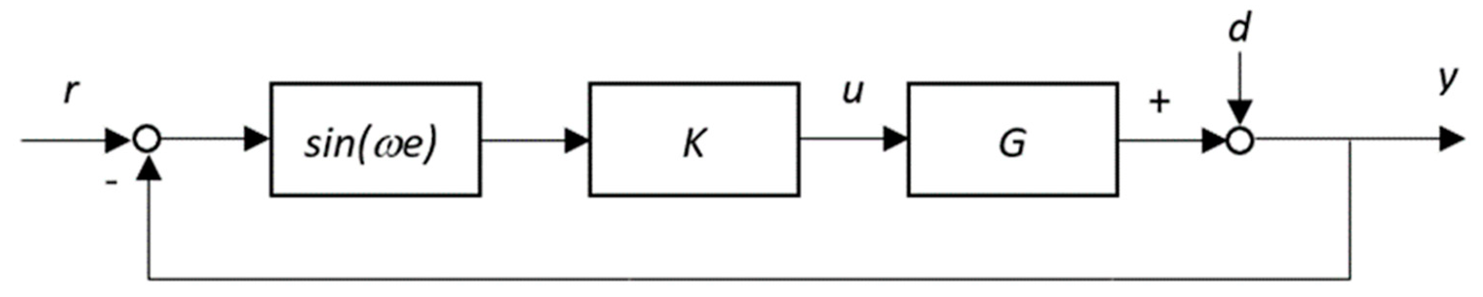
Impact on the stability of the designed control system: in setting the water level as a step-function signal, amplitude is H r , the steady-state output of water level H as illustrated in Figure 1 can be expressed as follows, where the amplitude is H r :
H ( ) = lim s 0 s G K d 1 + G K d H r s = lim s 0 K 0 s ( T 0 s + 1 ) ( 1 K 0 T 1 + T 0 K 0 T s ) d 1 + K 0 s ( T 0 s + 1 ) ( 1 K 0 T 1 + T 0 K 0 T s ) d H r = H r
Thus, the output steady-state error is 0, and there is no additional impact on the system stability of nonlinear control using the sine function.
(2)
Impact on the dynamic property of the designed control system: the transfer function from input H r to output H of the system is
H H r = G K d 1 + G K d
Because ω < 1 , based on closed-loop gain theory, GK, which represents the characteristics of the open-loop frequency of the control system, meets the requirements of high gain at low frequency and low gain at high frequency [1]. Consequently, in the low-frequency scope, comparing Equation (28) and the closed-loop transfer function G K / ( 1 + G K ) of the standard feedback system, there is little impact by introducing ω into the system.
(3)
Impact on the output of the designed control system: the transfer function from input H r to the steady-state value of input water flow Q i is
Q i H r = K d 1 + G K d
The analysis in (2) is also applicable in this case; however, it should be noted that the deduction of the numerator is more significant than the deduction of the denominator. As a result, the control output is reduced by introducing ω into the system.

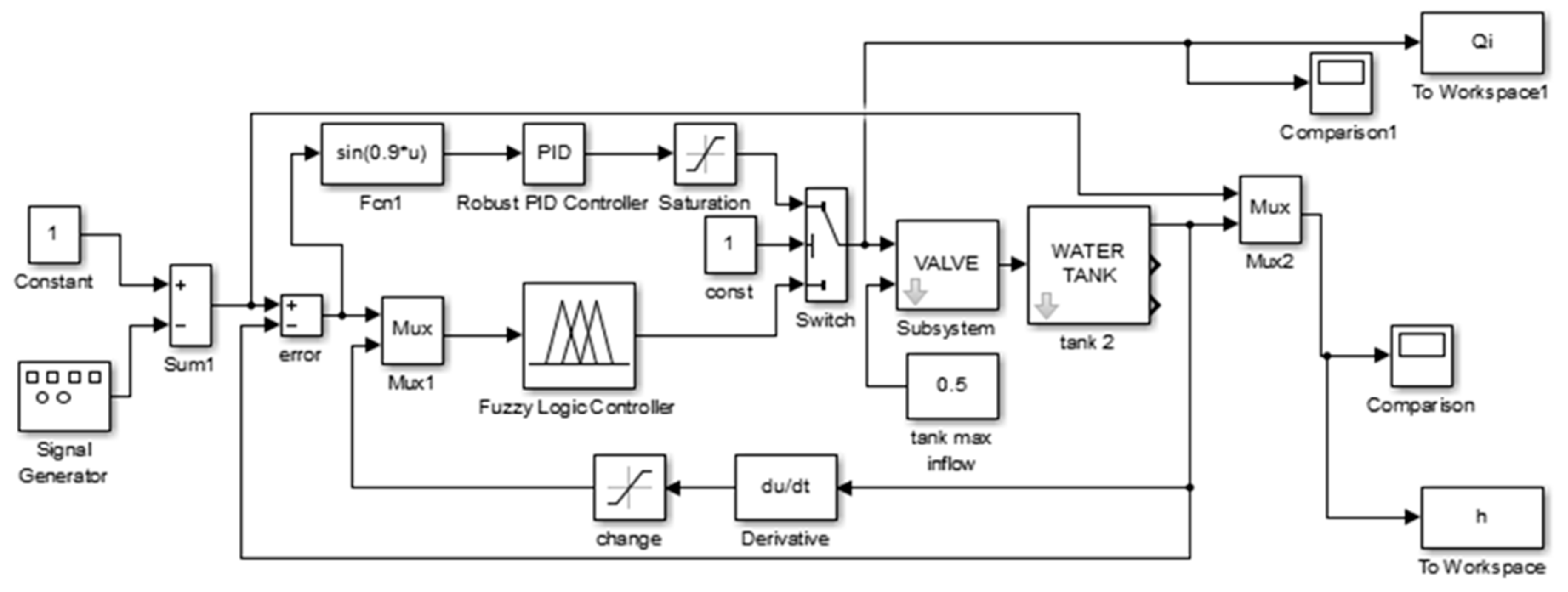
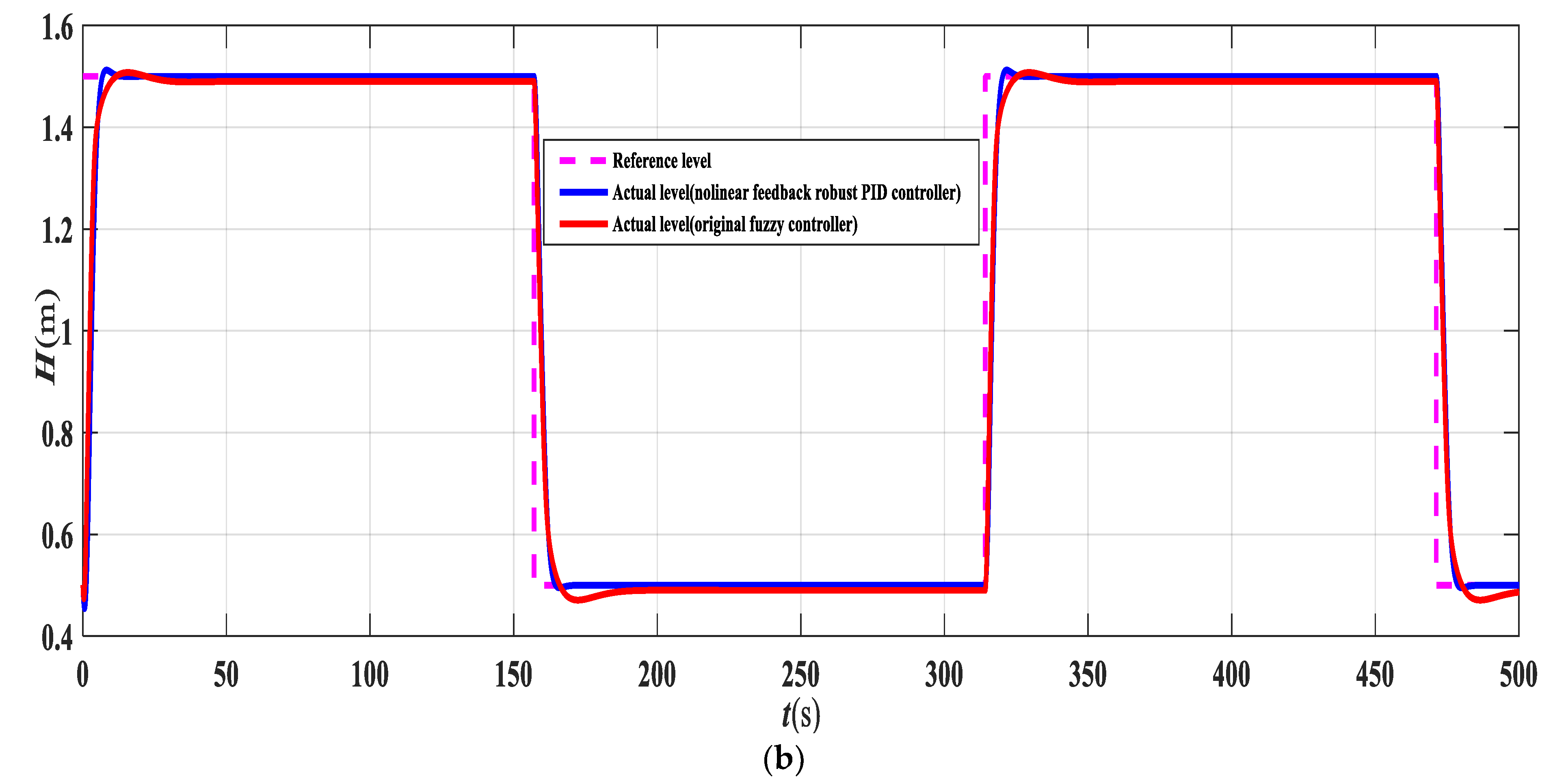
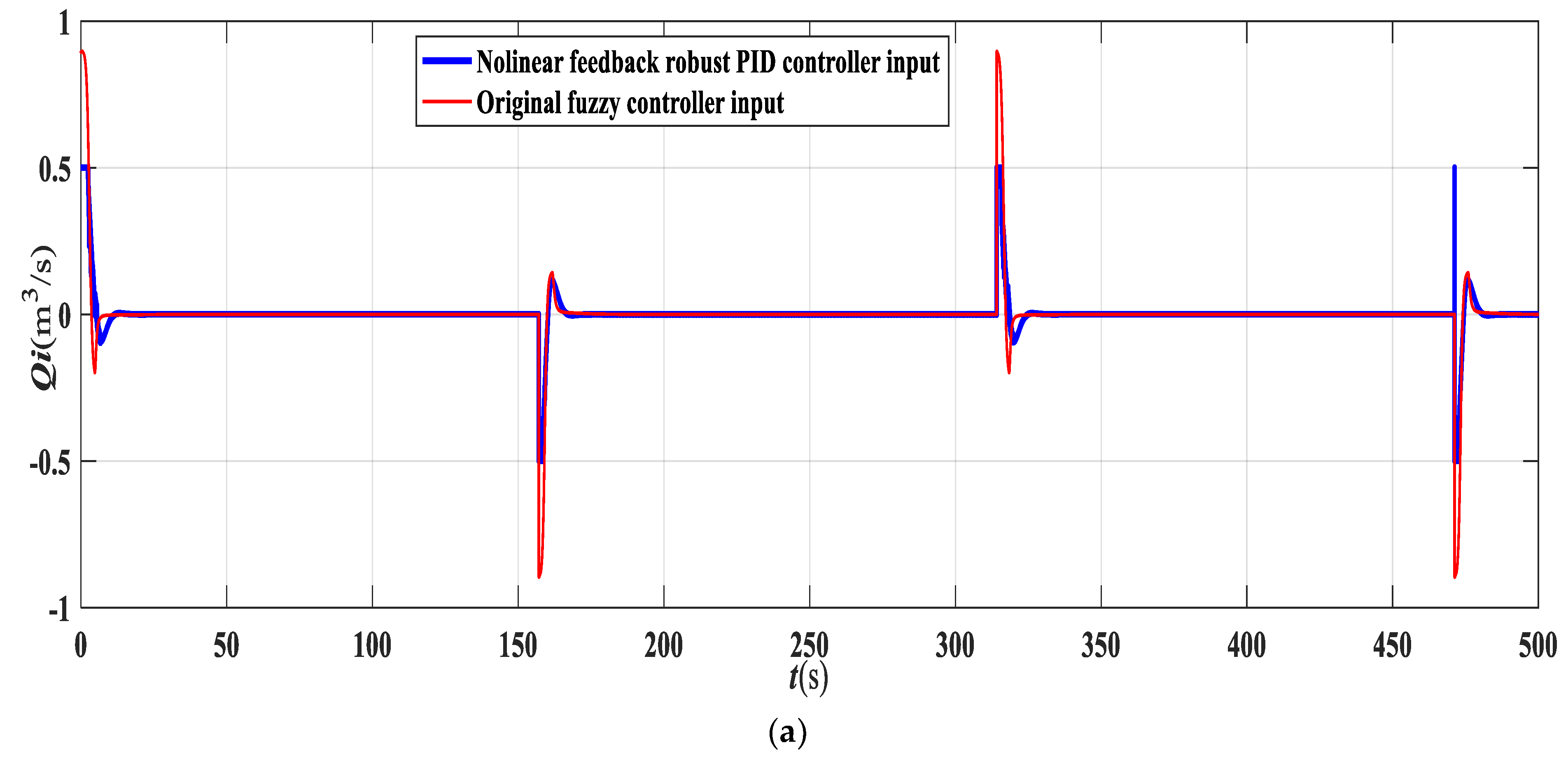
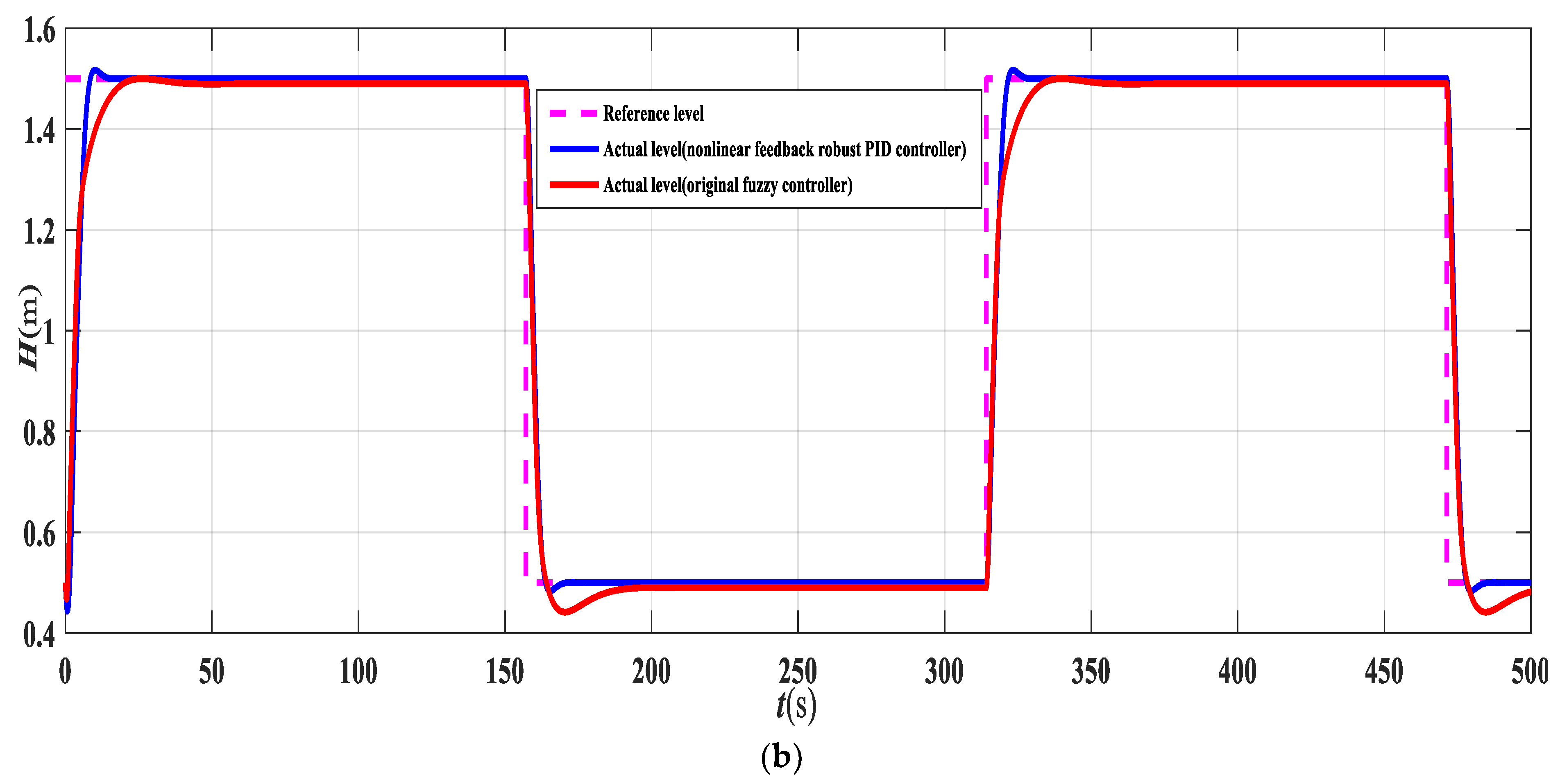
4. Simulation Experiments and Results

Evaluation of the models and algorithms discussed in Section 2 was performed using the Simulink toolbox, and a simulation diagram was designed, as illustrated in Figure 2. The robust PID controller proposed in [24] demonstrated more robust stability and simplicity than the original fuzzy PID controller proposed in [25] where the detailed information of all settings in relation to the fuzzy control are preset and already embedded in the program. The enhanced PID controller proposed in this study is a sine function-based nonlinear feedback controller that aims to achieve energy-saving performance.
The input signal is corelated with amplitude in the form of a square wave varying from 0.5 m to 1.5 m. Although (2) is considered to construct the PID controller, a nonlinear mathematic modeling which is more complicated is employed for simulations. On the condition that the maximum inflow rate of the tank is maintained at 0.5 m3/s, the results of nonlinear feedback robust PID control can be used to determine that the mean control input is 0.0153 m3/s. The simulation results are presented in blue curve of Figure 3a,b, where Figure 3a displays the curve of the control input and Figure 3b displays the curve of the water level. No overshooting occurs, and quick tracking is achieved. Because a complex nonlinear model is used in the simulation whereas a simplified linear model is used to design the controller, system robustness is ensured.
As illustrated in red curve of Figure 3, the simulation results of the original fuzzy controller reveal that the mean control input is 0.0228 m3/s. By collating the nonlinear feedback robust PID control and original fuzzy control, it can be seen that overshoot which is around 6.7% has been reduced and the response speed in terms of setting time (5.25 s) is increased when using nonlinear feedback robust PID control. Because the mean control input is reduced by 32.9%, energy-saving is achieved by introducing the sine function into nonlinear feedback control.
When the inflow rate is reduced from 0.5 m3/s to 0.4 m3/s, the simulation results of the nonlinear feedback robust PID controller demonstrate that the mean control input is increased to 0.0203 m3/s (as illustrated in blue curve of Figure 4); however, the output performance hardly changes.
The simulation results of the original fuzzy controller, as illustrated in red curve of Figure 4, indicate that the mean control input is increased to 0.0257 m3/s, and the output performance is reduced. The nonlinear feedback effect remains better performance over the original fuzzy controller even when the inflow rate is reduced. The mean control input is reduced by up to 21%, which demonstrates that the energy efficiency of sine function-based nonlinear feedback control is superior to that of original fuzzy control.
The following comprehensive control performance index J as shown in Equation (30) is used to evaluate the two aforementioned control algorithms:
J = ( Q i 2 + Δ H 2 ) d t
In accordance with Equation (30), J is a function that is used to measure the performance index of the control input value and output error; that is, the performance index is better with a smaller J. The above simulation result, as summarized in Table 2 through a quantitative comparison, positively confirms the effectiveness of the proposed algorithm.

5. Conclusions

In this study, two different control modes—nonlinear feedback robust PID control and conventional fuzzy control—are mathematically discussed and analyzed by controlling the water level in a tank. The nonlinear control mode yields the most energy-efficient performance, reducing the mean control input by 32.9% and improving the performance index by 24%. The proposed nonlinear PID controller using the sine function is developed in accordance with the design goals discussed in a previous study [24]. The specifications and features with respect to robust stability and simplicity are retained while the energy-saving capability is significantly increased. In this paper, the sine function is used in nonlinear feedback control to achieve the objective of using less energy. The proposed algorithm applying sine function-based nonlinear feedback demonstrates advantages, such as energy efficiency, simplicity, and potential for extensive use in the industry. However, due primarily to the conditions and limitations of carrying out actual experiments which would be further strengthened in our future research, particularly for the implementation of the fluid level control onboard an ocean-going ship.

Author Contributions

Visualization, J.Z. & P.W.; Resources, Y.C. & P.W.; Validation, J.Z.; Writing—Review and Editing, J.Z. & Y.C.; Methodology, J.Z. & X.Z.; Supervision, X.Z. All authors have read and agreed to the published version of the manuscript.

Funding

This work is partially supported by the National Science Foundation of China (Grant No. 51679024), the Fundamental Research Funds for the Central University (Grant No. 3132016315), and the University 111 Project of China (Grant No. B08046).

Institutional Review Board Statement

Not applicable.

Informed Consent Statement

Not applicable.

Data Availability Statement

Not applicable.

Conflicts of Interest

The authors declare no conflict of interest.

References

  1. Zhang, X.K. Ship Motion Concise Robust Control; Science Press: Beijing, China, 2012. [Google Scholar]
  2. Kokotovic, P.; Arcak, M.C. Constructive nonlinear control: A historical perspective. Automatica 2001, 37, 637–662. [Google Scholar] [CrossRef]
  3. Zhang, X.K.; Jin, Y.C. Control. System Modeling and Numerical Simulation (Second Edition); Dalian Maritime University Press: Dalian, China, 2013. [Google Scholar]
  4. Li, X.S.; Li, Z.A. The Application of Linear and Nonlinear Water Tanks Case Study in Teaching of Process Control. In IOP Conf. Series: Earth and Environmental Science. Proceedings of the 3rd International Conference on Advances in Energy Resources and Environment Engineering, Harbin, China, 8–10 December 2017; IOP Publishing: Bristol, UK, 2018. [Google Scholar]
  5. Robert, B.; Marian, B.; Rafal, G. A New Look at Water Tanks Systems as Control Teaching Tools. In Proceedings of the 20th World Congress of the International-Federation-of-Automatic-Control (IFAC), Toulouse, France, 9–14 July 2017. [Google Scholar]
  6. Zhao, T.Y.; Li, P.; Cao, J.T. Study of Interval Type-2 Fuzzy Controller for the Twin-tank Water Level System. Chin. J. Chem. Eng. 2012, 20, 1102–1106. [Google Scholar] [CrossRef]
  7. Namazov, M.; Alili, A. Design of stable takagi sugeno fuzzy control system for three interconnected tank system via LMIs with constraint on the output. IFAC-Pap. OnLine 2018, 51, 721–726. [Google Scholar] [CrossRef]
  8. Thamallah, A.; Sakly, A.; M’sahli, F. A new constrained PSO for fuzzy predictive control of Quadruple-Tank process. Measurement 2019, 136, 93–104. [Google Scholar] [CrossRef]
  9. Yang, Z.J.; Sugiura, H. Robust nonlinear control of a three-tank system using finite-time disturbance observers. Control. Eng. Pract. 2019, 84, 63–71. [Google Scholar] [CrossRef]
  10. Zhong, X.; Peng, L.X.; Yi, C.; Zhang, J. The research on intelligent prediction algorithm for water level control of tank. J. Nonlinear Convex A 2009, 20, 1271–1281. [Google Scholar]
  11. Kumar, E.G.; Arunshankar, J. Control of nonlinear two-tank hybrid system using sliding mode controller with fractional-order PI-D sliding surface. Comput. Electr. Eng. 2018, 71, 953–965. [Google Scholar]
  12. Jiri, V.; Petr, D. Simulation of Adaptive LQ Control of Nonlinear Process. Stud. Inf. Control 2012, 20, 215–324. [Google Scholar]
  13. Sarailoo, M.; Rahmani, Z.; Rezaie, B. A novel model predictive control scheme based on bees algorithm in a class of nonlinear systems: Application to a three tank system. Neurocomputing 2015, 152, 294–304. [Google Scholar] [CrossRef]
  14. Arkadiusz, M.; Argyrios, Z. Plc-based discrete fractional-order control design for an industrial-oriented water tank volume system with input delay. Fract. Calc. Appl. Anal. 2018, 21, 1005–1026. [Google Scholar]
  15. Prasanta, R.; Kar, B.; Roy, B.K. Fractional Order PI-PD Control of Liquid Level in Coupled Two Tank System and its Experimental Validation. Asian J. Control 2017, 19, 1699–1709. [Google Scholar]
  16. Guan, W.; Cao, J.; Su, Z. Steering Controller Design for Smart Autonomous Surface Vessel Based on CSF L2 Gain Robust Strategy. IEEE Access 2019, 7, 109982–109989. [Google Scholar] [CrossRef]
  17. Zhang, Q.; Zhang, X.K. Nonlinear Improved Concise Backstepping Control of Course Keeping for Ships. IEEE Access 2019, 7, 19258–19265. [Google Scholar] [CrossRef]
  18. Dong, Z.; Bao, M.; Zheng, X.; Yang, X.; Song, L.; Mao, Y. Heading Control of Unmanned Marine Vehicles Based on an Improved Robust Adaptive Fuzzy Neural Network Control Algorithm. IEEE Access 2019, 7, 9704–9713. [Google Scholar] [CrossRef]
  19. Tian, Y.; Wang, B.; Chen, D.; Wang, S.; Chen, P.; Yang, Y. Design of a Nonlinear Predictive Controller for a Fractional-Order Hydraulic Turbine Governing System with Mechanical Time Delay. Energies 2019, 12, 4727. [Google Scholar] [CrossRef] [Green Version]
  20. Ha, L.N.N.T.; Bui, D.H.P.; Hong, S.K. Nonlinear Control for Autonomous Trajectory Tracking While Considering Collision Avoidance of UAVs Based on Geometric Relations. Energies 2019, 12, 1551. [Google Scholar] [CrossRef] [Green Version]
  21. Rodríguez-Licea, M.-A.; Pérez-Pinal, F.-J.; Nuñez-Perez, J.-C.; Herrera-Ramirez, C.-A. Nonlinear Robust Control for Low Voltage Direct-Current Residential Microgrids with Constant Power Loads. Energies 2018, 11, 1130. [Google Scholar] [CrossRef] [Green Version]
  22. Zhang, R.F.; Chen, D.Y.; Ma, X.Y. Nonlinear Predictive Control of a Hydropower System Model. Entropy 2015, 17, 6129–6149. [Google Scholar] [CrossRef] [Green Version]
  23. Zhang, X.K.; Jin, Y.C. Robust PID controller based on closed-loop gain shaping algorithm and its application. In Proceedings of the International Conference on Machine Learning and Cybernetics, Baoding, China, 12–15 July 2009. [Google Scholar]
  24. Zhang, X.K.; Jia, X.L. Robust PID Algorithm based on Closed-loop Gain Shaping and its application on level control. Shipbuild. China 2000, 41, 35–38. [Google Scholar]
  25. Roger, J. Fuzzy Toolbox in Matlab Manuel; The Math Works, Inc.: Natick, MA, USA, 1998. [Google Scholar]
Figure 1. Nonlinear feedback control system.
Energies 14 07602 g001
Figure 2. Simulation diagram of fuzzy controller and nonlinear robust proportional–integral–derivative (PID) controller using sine function.
Energies 14 07602 g002
Figure 3. Simulation results of nonlinear feedback robust proportional–integral–derivative (PID) controller and original fuzzy controller. The inflow rate is 0.5 m3/s. (a) Curve of control input. (b) Curve of water level.
Energies 14 07602 g003aEnergies 14 07602 g003b
Figure 4. Simulation results of nonlinear feedback robust proportional–integral–derivative (PID) controller and original fuzzy controller. The inflow rate is 0.4 m3/s. (a) Curve of control input. (b) Curve of water level.
Energies 14 07602 g004aEnergies 14 07602 g004b
Table 1. Parameters of the water tank.
No.ItemParameter
1Height of tank2 m
2Area of tank base1 m2
3Cross-sectional area of the pipe0.05 m2
4Original water level0.5 m
5Max inflow rate of water intake0.5 m3/s
Table 2. Comparison of closed-loop performance between two algorithms.
The Maximum Inflow Rate Is 0.5 m3/sThe Maximum Inflow Rate Is 0.4 m3/s
Nonlinear feedback robust PID algorithm456.1608.9
Fuzzy control algorithm600.0651.4
Variable rate to the robust PID algorithm (%)24.0%6.5%
Publisher’s Note: MDPI stays neutral with regard to jurisdictional claims in published maps and institutional affiliations.

