Article

Influence of the Refrigerant Charge on the Heat Transfer Performance for a Closed-Loop Spray Cooling System

1
College of Petroleum Engineering and Energy, Changzhou University, Changzhou 213164, China
2
College of Urban Construction, Nanjing Tech University, Nanjing 210009, China
*
Authors to whom correspondence should be addressed.
Energies 2021, 14(22), 7588; https://doi.org/10.3390/en14227588
Submission received: 13 October 2021 / Revised: 4 November 2021 / Accepted: 10 November 2021 / Published: 12 November 2021

Abstract

:
With the rapid increase of heat flux and demand for miniaturization of electronic equipment, the traditional heat conduction and convective heat transfer methods could not meet the needs. Therefore, the spray cooling experiment was carried out to obtain the basic heat transfer and cooling process. In this experiment, the spray cooling system was set up to investigate the influence of refrigerant charge on heat transfer performance in steady-state, dynamic heating, and dissipating processes. In a steady-state, the heat transfer coefficient increased with the rise of the refrigerant charge. In the dynamic dissipating process, both heat flux and heat transfer coefficient decreased rapidly after the critical heat flux, and the surface temperature drop point of each refrigerant charge was presented. The optimum refrigerant charge was provided considering the cooling parameters and the system operating performance. When the refrigerant operating pressure was 0.5 MPa, the spray cooling process presented with the higher heat flux, heat transfer coefficient, and cooling efficiency in this experiment. Meanwhile, the suitable surface temperature drop point and more gentle heat flux curves in the nucleate boiling region were obtained. The research results will contribute to the spray cooling system design, which should be operated before departure from the nucleate boiling point for avoiding cooling failure.

1. Introduction

As the increasing requirements in severe integration and miniaturization of electronic equipment, especially in the fields of advanced radar, high-performance laser weapons, and others, the conventional heat transfer methods such as simple single-phase convective could not contain the demand. Introducing reliable and efficient cooling technology has become urgent work. As a result, spray cooling technology casually attracts many researchers because of various heat transfer processes including evaporation, boiling, and convection heat transfer.
Due to its higher heat transfer coefficient, better surface temperature uniformity, smaller heat change temperature difference [1,2,3], spray cooling is considered an effective technology in the field of great heat flux dissipation. In spray cooling, the fluid working fluid is well-atomized under certain pressure and sprayed onto the surface to cool the object. The heat transfer mechanism of spray cooling involves complex multiphase flow. Researchers generally believe that spray cooling includes droplet impact, surface erosion, liquid film evaporation, and boiling process [4].
Many researchers have studied the droplet scouring process on the surface. Grissom et al. [5] found that the droplets crash into smaller droplets and shape a thin liquid film on the heating surface during the spray process. Fabbri et al. also observed the liquid film on the heating surface. He thought the thickness and breaking speed of the liquid film were the main influence of spray cooling heat transfer [6]. Hesih et al. [7] experimentally studied water spray cooling, he found that in small spray flow, the evaporation heat transfer performance depends mainly on the wetting capacity of the heating surface. In almost the same period, boiling heat transfer in the liquid film became a hot study topic, especially the boiling bubble morphology. Pais et al. [8] found that at higher surface temperature, the nucleation center of boiling bubbles appeared on the liquid film and the heating surface because of secondary nucleation occurring in process of passing through the liquid film. Yang et al. [9,10] set up the visualized spray cooling bench with water as working fluid. The results showed that secondary nucleation is the main influence of spray cooling.
The influences of spray cooling heat transfer performance are numerous including the characteristic of nozzle atomization, heating surface, working fluid, and operating environment, etc. [3,4]. Qian et al. [11] carried out the R134a spray cooling experiment. The result showed that with the rise of flow rate, the critical heat flux raises and the maximum critical heat flux reaches 94.75 W/cm2. Hou et al. [12] set up a spray system experiment bench with R22. It was found that under higher heat flow, the influence of low inlet pressure on the heat transfer coefficient and surface temperature is more apparent than that of high inlet pressure. There is an optimal inlet pressure to obtain the maximum critical heat flux, which was about 276.1 W/cm2. Liu et al. [13,14] conducted experiments on the R22 closed spray cooling system. He found that critical heat flux increased with the rise of nozzle entrance pressure within the experimental pressure range. Li et al. [15] investigated the influence of working fluid flow and inlet temperature on the heat transfer performance of the R134a spray system. The result showed that the heat transfer coefficient first increases and tends to be stable with the rise of flow. Liu et al. [16] studied the spray chamber pressure in the R134a spray cooling system. It was found that critical heat flux and heat transfer coefficient went up with the rise of chamber pressure. Meanwhile, the dimensionless correlation of heat flux was improved by adding Webber number and Jacob number.
Peng et al. [17] researched the transient spray cooling heat transfer with R21 as a working fluid. The heat transfer deterioration temperature point decreased with the rise of heat flux and spray distance and increased with the rise of working fluid flow. Cao et al. [18] carried out an R134a spray cooling experiment. The results showed that the chamber pressure was the main influence on the critical heat flux. The maximum critical heat flux was 130 W/cm2. Cai [19] numerically studied the heat transfer characteristics of spray cooling at the range of 50 to 170 W/cm2. He found that the heat transfer coefficient increases with the rise of heat flux. In the nucleate boiling regime, the wall film was thinner with a smaller velocity compared with those in the no-boiling regime. In addition, Xie et al. [20] used the compact spray chamber to carry the spray cooling experiment with R134a. It was found that the larger spray space and reasonable drainage design alleviated the liquid immersion on the heating surface, which increased the share of the evaporation and got the larger heat flux.
Refrigerants have become a widely used spray working fluid due to their thermophysical properties. Zhou et al. [21,22] established a spray cooling system with R134a and R404 as a working medium. They obtained optimum spray distance and spray pressure of the two working fluids. The contrast of R134a and R22 on the spray cooling performance was carried [23]. The result showed the heat transfer performance of R22 was better due to the excellent thermophysical properties.
The above researches were primarily focused on the mechanism of surface heat transfer and flow, influencing factors under steady-state˙. However, in the closed-loop spray system, the influence of refrigerant charge on the transient heat transfer performance and system operation efficiency is not clear, which needs further improvement. In this study, the spray cooling experiment system with R22 as working fluid is established. The influence of refrigerant charge on the process of steady-state, dynamic heating and dissipation, heat transfer performance, and comprehensive efficiency are studied.

2. Materials and Methods

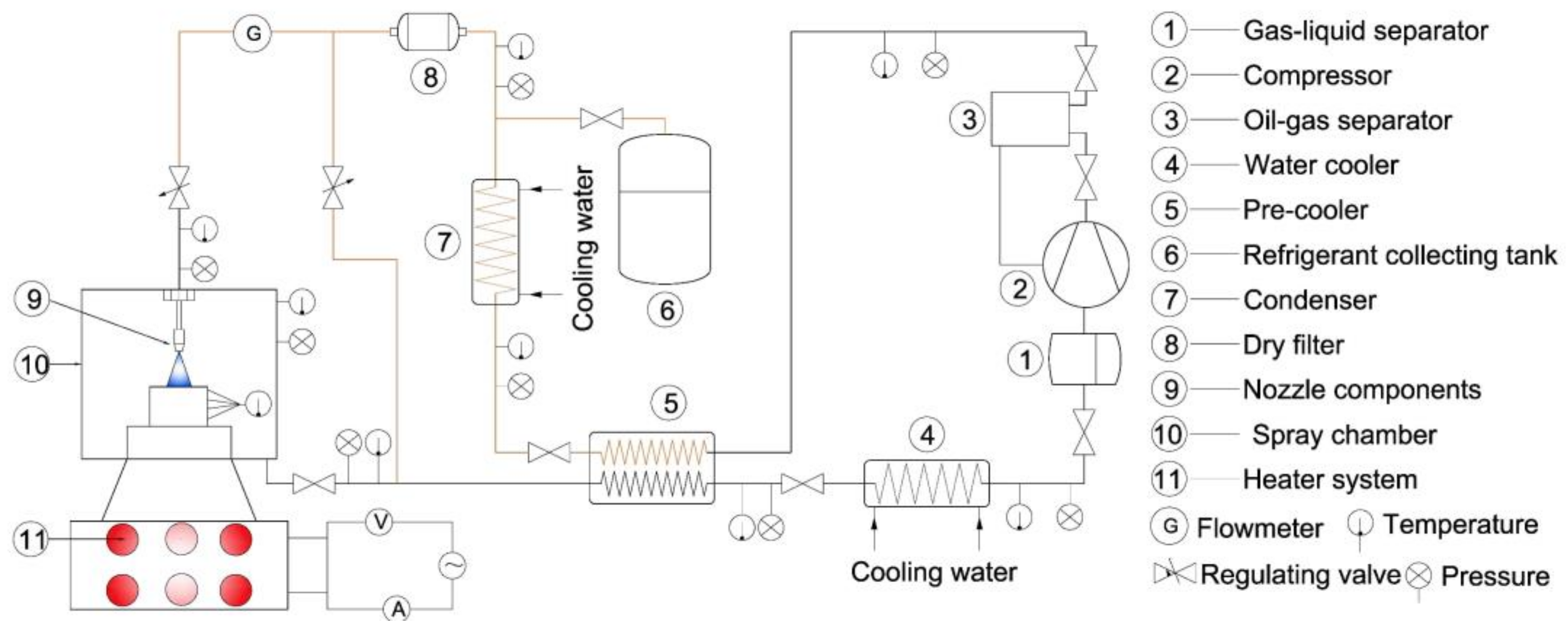
2.1. Experimental System

The closed-loop spray cooling system, as shown in Figure 1, composes of the working fluid feeding system, spray chamber, heating system, and acquisition system. The working principles are as follows: firstly, the gas fluid flows out from the gas-liquid separator, then be compressed in the compressor and enters into the precooler. Then, the fluid condenses into a supercooled liquid state in the condenser. ˙After passing through the flowmeter, the super-cooled working fluid is shot onto the upper surface of a copper column by the nozzle. The well-atomized droplets impact the upper surface and dismiss the heat by evaporation or boiling modes. Then the fluid enters the precooler for absorbing heat to keep the fluid gas. The gas fluid should flow through the water cooler to make inlet temperature meet the inter parameter of the compressor before flowing back into the compressor for the cycle. In addition, the main components of the device and its definition have been clearly shown in Figure 1 for the convenience of readers.
In this study, the different heat fluxes can be obtained by adjusting the power of the heating system. During the experiment of refrigerant charge variation, the system was vacuumed each time before adding refrigerant. Due to the refrigerant charge weight of every system being different, the pressure of the spray chamber was used instead of the refrigerant charge.
R22 has a low boiling point and operating pressure, which could provide exploratory work for future experiments with R134a and R410A. Therefore, R22 was selected as the working fluid which does not mean it is recommended by this paper.

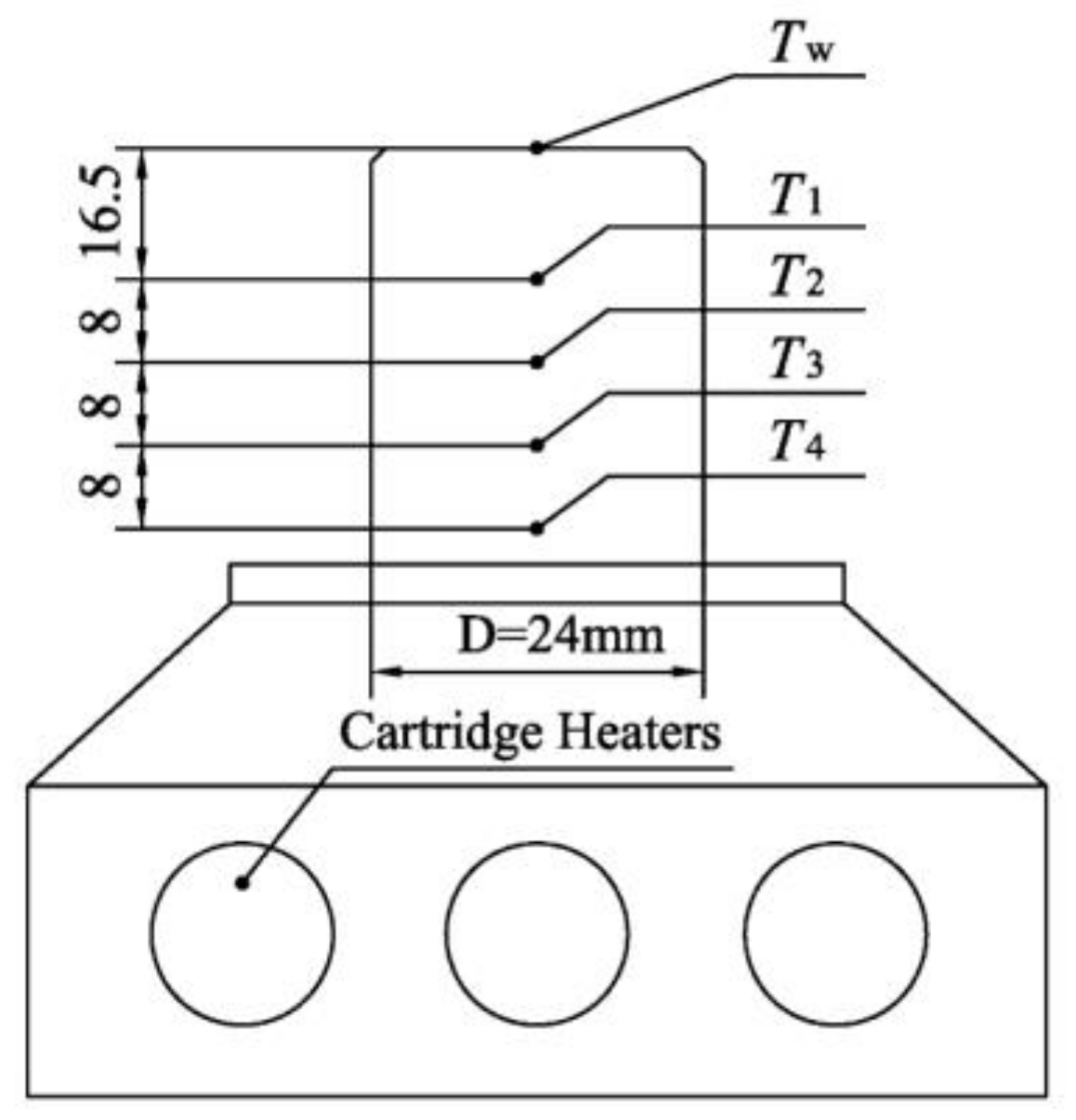
2.2. Spray Chamber and Heating Block

The spray chamber in this system was shown in Figure 2. The spray chamber is good sealing. The outside surface of the chamber is coated by aluminum silicate fiber cotton isolated for heat isolation. The windows are used to observe the spray flow state of the working fluid.
Figure 3 shows the structure of the heating block and thermocouples. Alumina silicate glass fiber wool is filled between the heating block and the bottom cavity to achieve heat insulation. The diameter of the copper column is 24 mm. The surface temperature could be obtained by the data collected by the four thermocouples. The distances between thermocouple T1 to T4 are 8 mm, 8 mm, 8 mm, and 16.5 mm respectively.

2.3. Uncertainty Analysis

Table 1 shows the accuracy of the measurements in this paper.
The deviation of surface temperature, heat flux and, heat transfer coefficient are ±2.9%, ±5.6% and ±5.4% according to the theory of error transfer [24].

2.4. Data Process

2.4.1. Data Calculation

Good heat insulation is adopted on the peripheral side of heating block, so the axial temperature profiles of the copper column follow the transient one-dimensional heat conduction law [13]. In addition, the specific heat capacity of pure copper is considered in transient heat transfer. The transient heat flux of the copper column is calculated by:
q = λ T 2 T 1 δ 1 δ 1 ρ c p Δ T 1 Δ τ
where ρ is density, c p is specific heat capacity and λ is thermal conductivity, δ 1 is the distance of T 1 and T 2 , Δ τ is one step time, Δ T 1 is a temperature difference of T 1 in one step time.
The surface temperature could be obtained by:
T w = T 1 q δ 2 λ
where T w is the surface temperature, δ 2 is the distance of T w and T 1 .
Coupling the surface convection boundary with heat flux boundary, the heat transfer coefficient is obtained:
h = q T w T in
where, T in is the inlet temperature of nozzle, °C;
In forced convection and boiling phase change heat transfer, the spray cooling heat transfer can be characterized by the dimensionless Reynolds number Re, Jacob number Ja and Weber number We.
R e = G m D μ
W e = ρ u 2 d 32 σ
J a = C p ( T w T sat ) L
where μ is dynamic viscosity, T sat is saturation temperature of the refrigerant. G m is volume flow rate, D is the equivalent diameter of the top surface. u is droplet velocity, d 32 is Sauter average diameter, T c is spray chamber temperature. σ is surface tension, and L is the latent heat of evaporation.

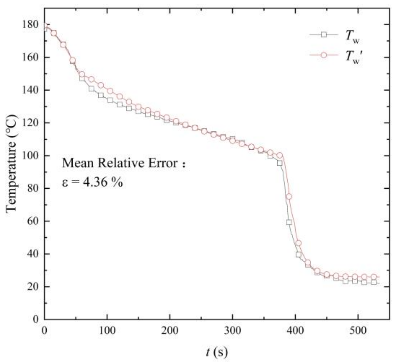
2.4.2. Reliability Verification

The differential and boundary equations of the copper column are obtained by the inverse heat conduction problem method IHCP [25]. The discretization integral equation of wage surface and interior in time and space are established. Subsequently, the equations are transformed into a matrix for calculating by Matlab software.
In the verification process, the heat transfer coefficient first is fitted based on the existing data. Then the predicted values T 1 , T 2 , T 3 , T 4 obtained by IHCP is contrast with actual values T 1 , T 2 , T 3 , T 4 . Once the deviation is acceptable, the heat transfer coefficient is available. Otherwise, it should be readjusted until the deviation is in the acceptable range. Then the predicted surface temperature T w is contrast with actual value T w . When the deviation is allowed, the calculation method presented could be available. The verification process is shown in Figure 4.
A deviation verification case is shown below: The deviation comparison of actual values and IHCP are in Figure 5. The mean relative deviation of IHCP and the actual values is proper, so the heat transfer coefficient is reliable. T w and T w are contrasted in Figure 6.
The mean relative deviation is just 4.36%. So taking the Equations (1) and (2) as the calculation equations is practical.

3. Results and Discussion

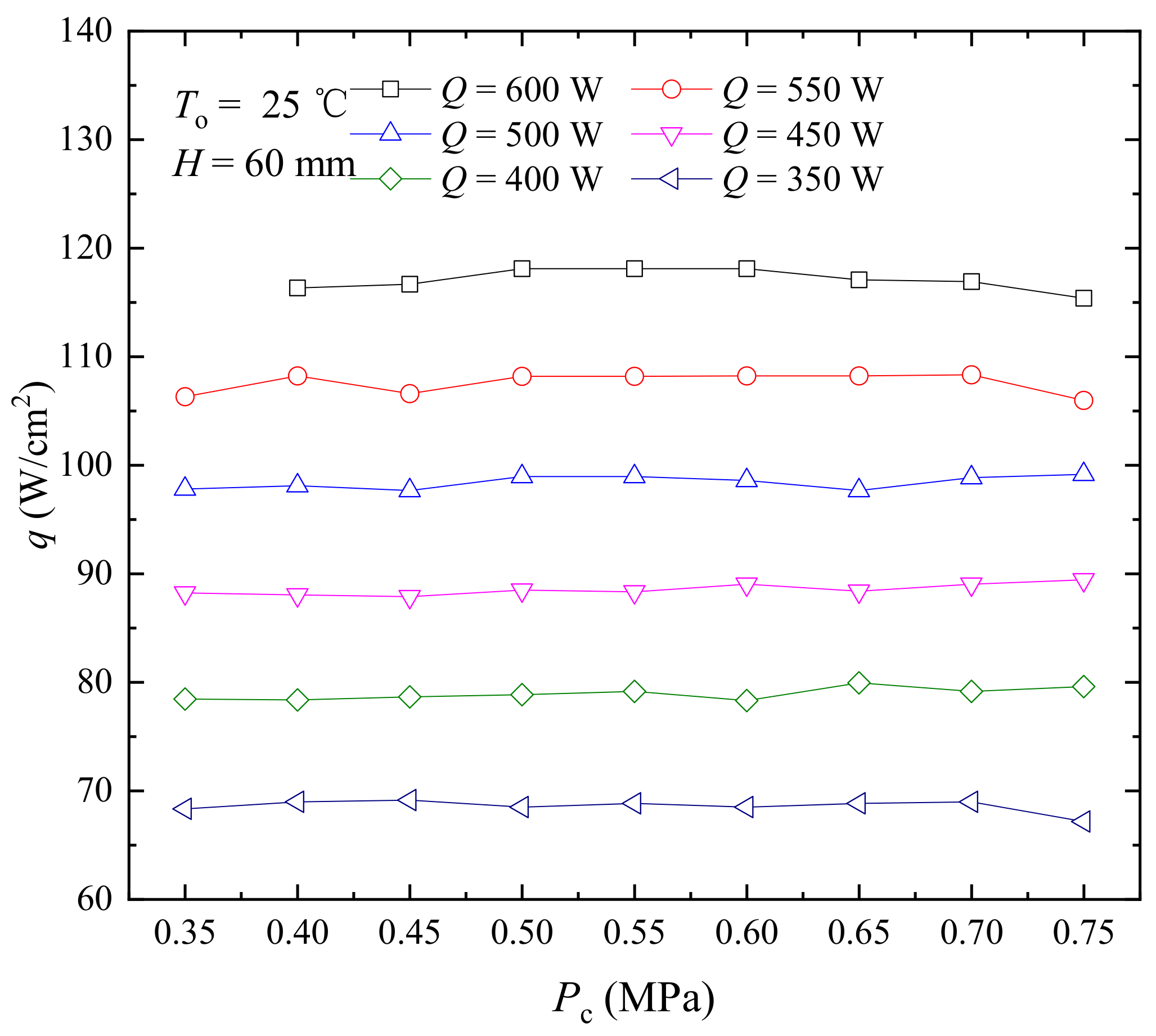
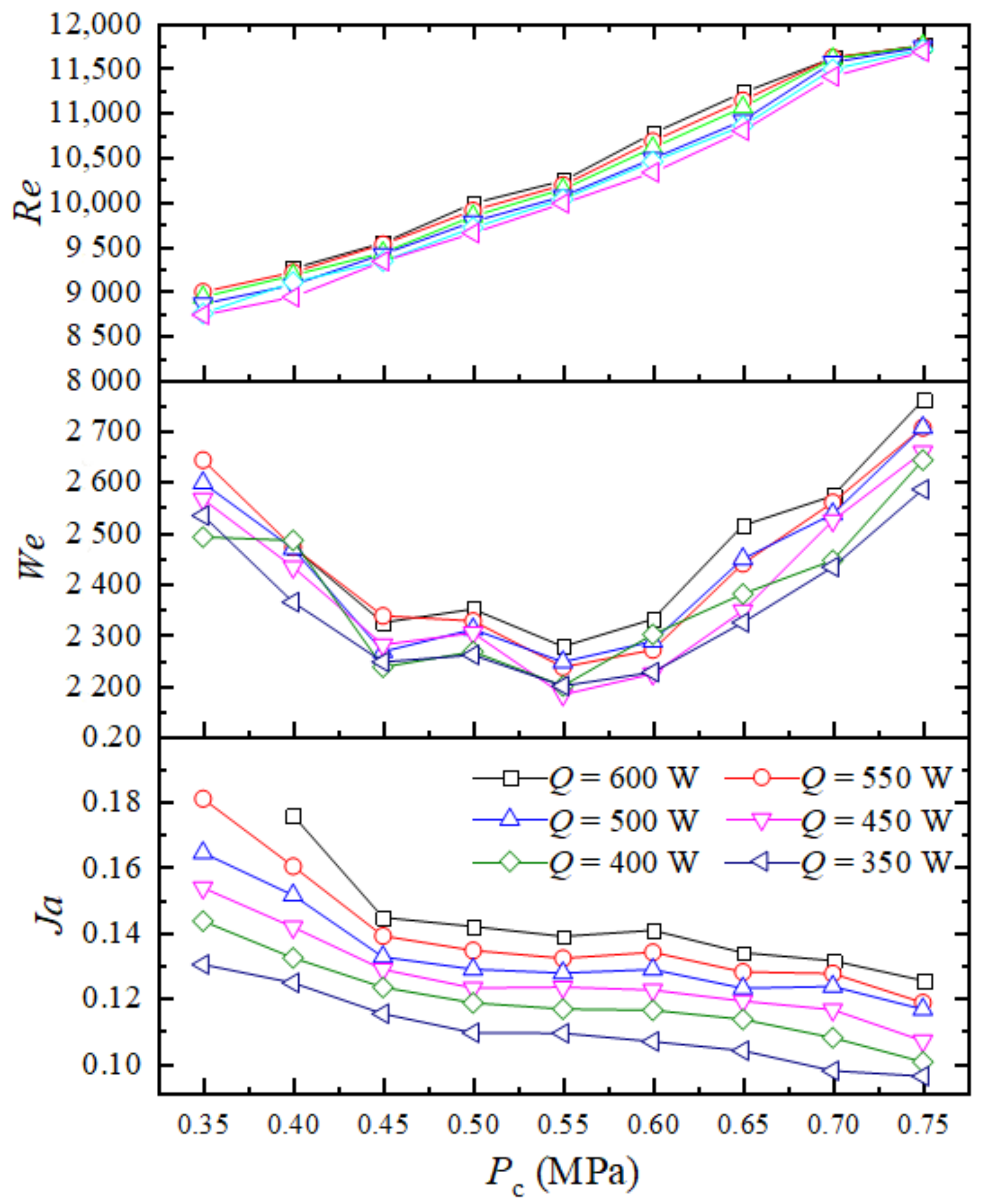
3.1. Effect of Refrigerant Charge on Spray Cooling Performance

Refrigerant charge is directly related to the performance of the cooling system. Under low refrigerant charge, the suction superheat of the compressor increases, the heat transfer of the evaporator and the refrigerating capacity will reduce. Under high refrigerant charge, the condensing pressure, the refrigerating capacity, and the energy consumption will increase, thus for the closed-loop spray cooling system, there will exit an optimum refrigerant charge. In order to investigate the refrigerant charge and its influence on the performance of the system more directly, the spray chamber pressure is used to reflect the change of refrigerant charge. In the experiment, the flow rate under each refrigerant charge is kept constant.
In the experiment, the nozzle type was 1/8GG-SS1.5, the spray height is adjusted to 60 mm, the flow control valve was kept at the maximum opening condition, and the bypass branch was closed. The ambient temperature was set at 25 °C, the spray chamber pressure was adjusted from 0.35 MPa to 0.75 MPa, and the heating power was adjusted from 350 W to 600 W at each charge pressure. The change of spray cooling heat transfer performance was emphatically analyzed.
As shown in Figure 7 and Figure 8, the surface heat flux didn’t change with the change of the refrigerant charge at the same heating power, and the heat transfer coefficient increased with the rise of the refrigerant charge. When the refrigerant charge increased, the pressure difference of the nozzle increased and the atomization was enhanced, so the heat transfer capability was enhanced by increasing the number of atomized droplets. In addition, when the refrigerant pressure was 0.35 MPa, the surface heat flux at 600 W heating power exceeded the critical heat flux and decreased rapidly. Spray cooling heat transfer entered the failure state, and therefore there was no comparability with other steady-state data. The influence of refrigerant charge on spray cooling performance was further explained by the dimensionless characteristic parameters We, Re, and Ja.
As shown in Figure 9, the increase of refrigerant charge will lead to the increase of spray droplet velocity. and the Re grows with the rise of chamber pressure. Besides, with the rise of refrigerant charge, the pressure of compressor inlet and outlet and the pressure of the throttling will also increase. As a result, the saturation temperature increases, and the overall trend of the Ja still decreases, although the surface temperature increases slightly. Meanwhile, the We shows the trend of decreasing first and then increasing. Under the same refrigerant charge, as the heating power increases, the Re and We change little, and the Ja increases, which shows that the intensity of boiling is more intense.

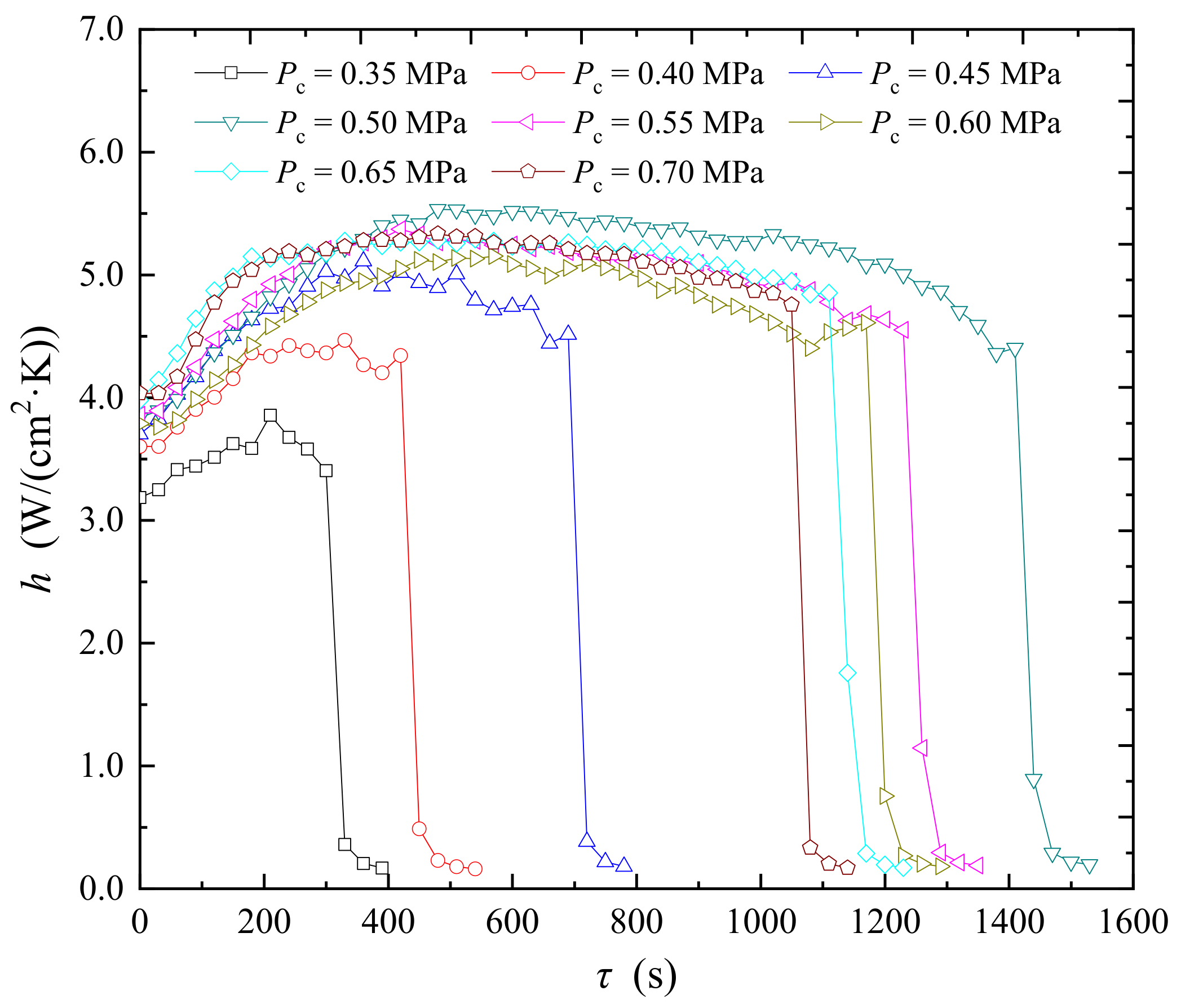
3.2. Analysis of Dynamic Heating Process under Different Refrigerant Charge

The critical heat flux is applied to characterize the heat transfer performance. In this section, the flow valve was in the maximum opening, and the bypass was closed. In addition, the heating power was first adjusted to 350 W, and when the system was stable, the heating power was kept at 900 W until the system reached critical heat flux. Changes in heat flux and heat transfer coefficient with time were observed under different refrigerant charges, as shown in Figure 7 and Figure 8.
It can be seen from Figure 10 and Figure 11, before critical heat flux, heat transfer coefficient and heat flux increased continuously, and the rate increased first and then decreased. While after critical heat flux, the heat transfer coefficient and heat flux decreased rapidly. It can be explained that the heating surface firstly entered the nucleate boiling stage with the heating power increasing, and the bubbles created from secondary nucleation appeared in the liquid film. The heat transfer coefficient and heat flux increase continuously with good heat transfer performance. With further rising of the heating power, the number of surface bubble nucleation increased greatly, and local dry-out phenomenon occurred. However, boiling heat transfer still existed in most areas, and heat flux continued to rise, but the rate decreased. In addition, because the local dry-out will weaken the heat transfer performance, the heat transfer coefficient showed a slightly decreasing trend. After critical heat flux, spray cooling was in a transition boiling state, the local dry-out evolved into the global dry outstate. The droplet and the heating surface were separated by a layer of gas film. The heat transfer performance deteriorated sharply, and the heat transfer coefficient and heat flux both decrease rapidly. The performance parameters under each charge are listed in Table 2.
In addition, it can be seen from Table 2 that in the dynamic heating process, when the spray chamber pressure was 0.5 MPa, the critical heat flux was about 162.3 W/cm2 and the time to the critical heat flux was extended to 1410 s, which meant that the time of the boiling heat transfer period was the longest under this chamber pressure. In addition, the heat transfer coefficient reached the highest value under this pressure. It is beneficial for making the system operation state before the departure from nucleate boiling point, and a higher heat transfer coefficient can be obtained under this pressure value. Where the departure from the nucleate boiling point is the left side position of the critical heat flux.
The thermophoresis forces may account for the temperature discontinuity. When the surface reaches the critical heat flux, the gradient of temperature near the surface also increases rapidly, resulting in a significant increase of the thermophoresis force. The velocity of the droplet will decrease sharply close to zero before reaching the heating surface, and the droplets do not contact the hot surface, evaporate into a gas film at high surface temperature. Due to the lack of droplet impacting heat transfer and the large heat transfer resistance of the gas film, the heat transfer continually deteriorates.

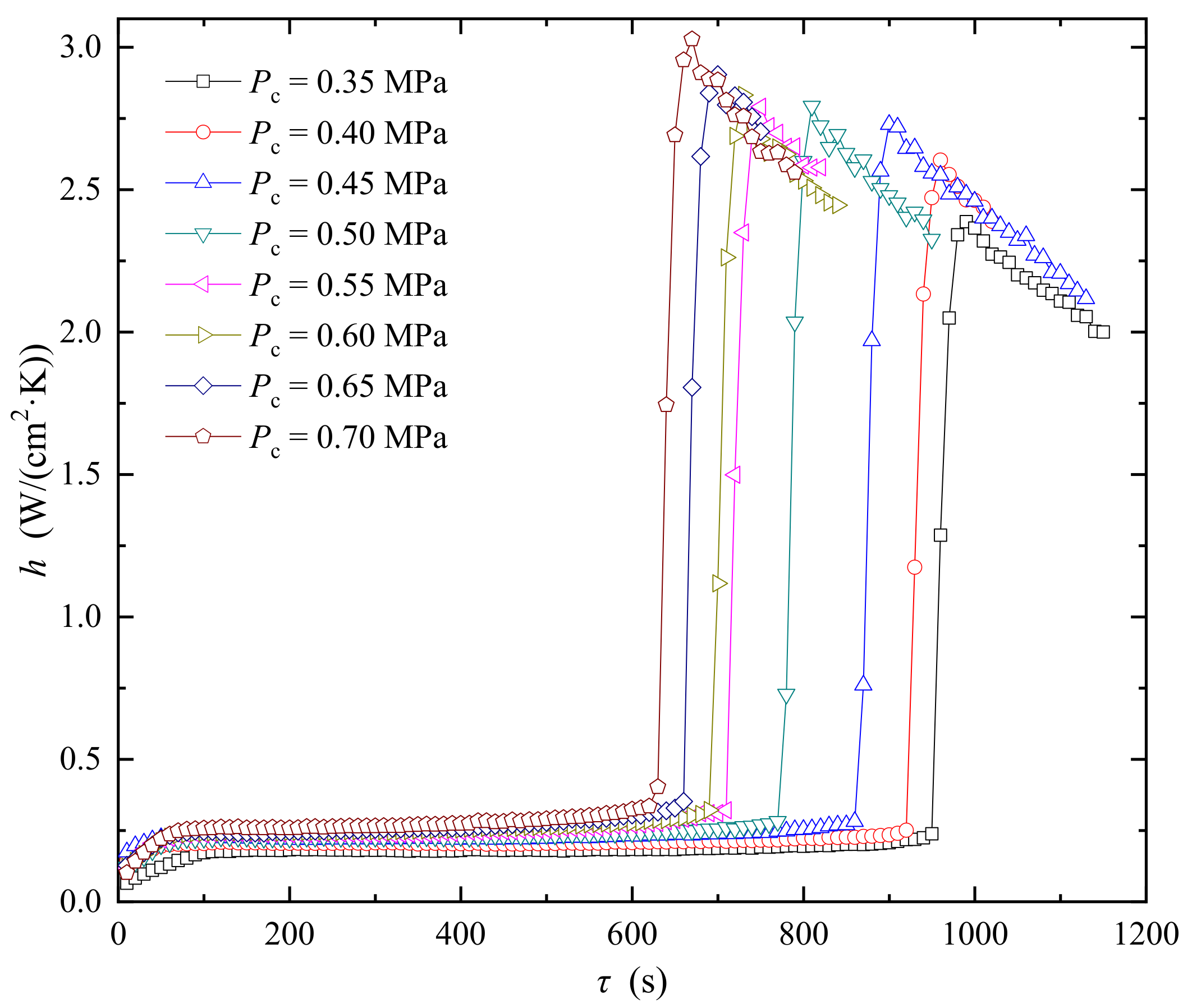
3.3. Analysis of Dynamic Dissipating Process under Different Refrigerant Charge

In this process, the heating power was first adjusted at 600 W. The cooling system starts to work when the surface temperature reaches 130 °C, and the curves of heat transfer coefficient and surface temperature under different refrigerant charges were observed.
It can be seen from Figure 12 and Figure 13 that when the heating surface maintains a high temperature, the heat transfer coefficient constantly keeps on 0.2 to 0.3 W/(cm2·K). While the surface temperature reaches to surface temperature drop point STD marked in Figure 12, the heat transfer coefficient rises rapidly and then decreases slightly. Where the surface temperature drop point is the transition point of film boiling and nucleates boiling in the transition boiling zone. The film boiling is mainly surface heat transfer mode when the temperature is higher than the surface temperature drop point. Because under high surface temperature, the spray cooling is in the transition-boiling region, the gas film generating on a high-temperature surface would obstacle the heat transfer. The heat transfer mode is believed to be the convection and gas heat conduction with a low heat transfer coefficient. From the view of thermophoresis force, the surface temperature gradient decreases rapidly as the surface temperature decreases, and thermophoresis force also decreases rapidly. The droplets have sufficient velocity to impact the heating surface under the action of gravity, and liquid film heat transfer appears. Thus, the evaporation and boiling heat transfer of the liquid film is resumed, the heat transfer coefficient shows an increase again. However, the boiling intensity decreases when the gas film disappears, and the heat transfer coefficient is slightly smaller than the value of the heating process.
In addition, it can be seen from Table 3 that in the dynamic dissipating process, the surface temperature drop point increases gradually with the increase of refrigerant charge, and the time required to reach the surface temperature drop point also decreases, but the decreasing amplitude of time decreases gradually. When the operating pressure of the spray chamber is 0.5 MPa, the surface temperature drop point is 57.37 °C which can meet most of the cooling requirements.

3.4. The Optimum Refrigerant Charge in Spray Cooling System with R22

In the experiments of dynamic heating and heat dissipation, the refrigerant charge affected the rising curve of heat flux in the nucleate boiling zone, which also affected the value of the surface temperature drop point. The concept of spray cooling efficiency is proposed for evaluating the comprehensive system performance.
η = q A Q c
where Qc is a theoretical refrigeration capacity.
The evaporating temperature, condensing temperature, sub-cooling, superheat, coefficient of performance, theoretical refrigeration capacity, and spray cooling efficiency under different refrigerant charges are shown in Table 4.
As shown in Table 4, with the increase of the refrigerant charge, the evaporating temperature, condensing temperature, and coefficient of performance increase gradually but the overall increasing amplitude decreases gradually. The sub-cooling increased gradually, and the superheat gradually decreased. However, the spray cooling efficiency increased first and then decreased, and when the pressure of the spray chamber is 0.5 MPa, the spray cooling reaches the optimum efficiency.
In summary, there is an optimum refrigerant charge for this experimental system, when the spray chamber operating pressure reaches 0.5 MPa, there will be a higher heat flux, heat transfer coefficient, and cooling efficiency for the R22 spray cooling system, which also contributes to controlling the cooling system running at departure from nucleate boiling point and avoiding cooling invalid.

4. Conclusions

In the study, the closed-loop spray cooling experiment system was established. The influence of refrigerant charge on the spray cooling heat transfer performance was investigated in the steady-state, dynamic heating, and dissipating process. The conclusions are as follows:
(1)
In the steady-state, the heat transfer coefficient increases with the rise of the refrigerant charge.
(2)
In the dynamic heating process, both heat flux and heat transfer coefficient increase with a reversed rate before the critical heat flux. After critical heat flux, both would decrease rapidly.
(3)
In the process of dynamic dissipation, the heat transfer coefficient increases sharply when it reaches the surface temperature drop point. In addition, with the increase of refrigerant charge, the surface temperature drops point increase, and the time to the point decrease conversely.
(4)
When the refrigerant operating pressure was 0.5 MPa, the spray cooling process presents with a higher heat flux, heat transfer coefficient, and cooling efficiency. Meanwhile, a suitable surface temperature drop point and a more gentle heat flux curve in the nucleate boiling regime were obtained.

Author Contributions

Conceptualization, N.Z.; experimental investigation, H.F.; validation, Y.G.; resources, W.L.; data curation, H.P.; writing—original draft preparation, H.F.; writing—review and editing, N.Z.; visualization Y.L.; supervision, Y.W.; project administration, S.D.; All authors have read and agreed to the published version of the manuscript.

Funding

This research was funded by the Natural Science Foundation of Jiangsu Province in China, grant number No. BK20180960.

Institutional Review Board Statement

Not applicable.

Informed Consent Statement

Not applicable.

Data Availability Statement

There was no data.

Conflicts of Interest

The authors declare no conflict of interest.

Abbreviations

Asurface area (m2)
cspecific heat capacity (J/(kg·K))
d32Sauter mean diameter (m)
Dsurface diameter (m)
Gmass flow rate (kg/s)
hheat transfer coefficient (W/(m2·°C)
Hnozzle height (m)
Llatent heat (J/kg)
mmass (kg)
Ppressure (MPa)
Qheating power (W)
qheat flux (W/m2)
Ttemperature (°C)
uspray velocity(m/s)
ydistance between thermocouples (m)
Greek
η spray cooling efficiency
λ thermal conductivity (W/(m·K))
μ dynamic viscosity (Pa·s)
ρ density (kg/m3)
σ surface tension (N/m)
τ time (s)
Subscripts
cchamber
ininlet
JaJacob number
mmass
oouter environment
PrPrandtl number
ReReynolds number
satsaturation
ththermophoresis force
WeWeber number
wheating surface

References

  1. Cheng, W.L.; Liu, Q.N.; Zhao, R.; Fan, H.L. Experimental investigation of parameters effect on heat transfer of spray cooling. Heat Mass Transf. 2010, 46, 911–921. [Google Scholar] [CrossRef]
  2. Zhao, R.; Cheng, W.L.; Liu, Q.N.; Fan, H.L. Study on heat transfer performance of spray cooling: Model and analysis. Heat Mass Transf. 2010, 46, 821–829. [Google Scholar] [CrossRef]
  3. Cheng, W.L.; Zhang, W.W.; Chen, H.; Hu, L. Spray cooling and flash evaporation cooling: The current development and application. Renew. Sustain. Energy Rev. 2016, 55, 614–628. [Google Scholar] [CrossRef]
  4. Wang, Y.Q.; Liu, M.H.; Liu, D.; Wang, L.; Guo, H. Heat transfer mechanism and influencing factors in spray cooling. High Power Laser Part. Beams. 2011, 23, 2277–2281. [Google Scholar] [CrossRef]
  5. Grissom, W.M.; Wierum, F.A. Liquid spray cooling of a heated surface. Int. J. Heat Mass Transf. 1981, 24, 261–271. [Google Scholar] [CrossRef]
  6. Fabbri, M.; Jiang, S.J.; DHir, V.K. A comparative study of cooling of high power density electronics using sprays and microjets. J. Heat Transf. Trans. ASME 2005, 127, 38–48. [Google Scholar] [CrossRef]
  7. Hsieh, C.C.; Yao, S.C. Evaporative heat transfer characteristics of a water spray on micro-structured silicon surfaces. Int. J. Heat Mass Transf. 2006, 49, 962–974. [Google Scholar] [CrossRef]
  8. Pais, M.R.; Chow, L.C.; Mahefkey, E.T. Surface roughness and its effects on the heat transfer mechanism in spray cooling. J. Heat Transf. 1992, 114, 211–219. [Google Scholar] [CrossRef]
  9. Yang, J.R.; Wong, S.C. On the discrepancies between theoretical and experimental results for microgravity droplet evaporation. Int. J. Heat Mass Transf. 2001, 44, 4433–4443. [Google Scholar] [CrossRef]
  10. Yang, J.R.; Wong, S.C. An experimental and theoretical study of the effects of heat conduction through the support fiber on the evaporation of a droplet in a weakly convective flow. Int. J. Heat Mass Transf. 2002, 45, 4589–4598. [Google Scholar] [CrossRef]
  11. Qian, Y.; Liu, J.H.; Li, M.; Liu, X.F.; Hou, Y. Experimental Study on Heat Transfer Performance of Phase change Spray cooling with R134a. J. Xi Jiaotong Univ. 2015, 49, 97–101. [Google Scholar]
  12. Hou, Y.; Liu, X.F.; Liu, J.H.; Li, M.J.; Pu, L. Experimental study on phase change spray cooling. Exp. Therm. Fluid Sci. 2013, 46, 84–88. [Google Scholar] [CrossRef]
  13. Liu, J.H.; Sun, W.; Liu, X.F.; Hou, Y. Influences of spray chamber pressure and nozzle bore diameter on spray cooling performance. High Power Laser Part. Beams 2013, 25, 2546–2550. [Google Scholar]
  14. Liu, J.H.; Li, M.J.; Liu, X.F.; Hou, Y. Experiment on Phase Change Spray Cooling of Closed Cycle with R22. J. Xian Jiaotong Univ. 2013, 47, 132–136. [Google Scholar]
  15. Li, Q.; Tie, P.; Xuan, Y.M. Investigation on heat transfer characteristics of R134a spray cooling. Exp. Therm. Fluid Sci. 2015, 60, 182–187. [Google Scholar] [CrossRef]
  16. Liu, J.H.; Xue, R.; Chen, L.; Liu, X.F.; Hou, Y. Influence of chamber pressure on heat transfer characteristics of a closed loop R134-a spray cooling. Exp. Therm. Fluid Sci. 2016, 75, 89–95. [Google Scholar] [CrossRef]
  17. Peng, C.; Xu, X.H.; Liang, X.A. Experimental study on temperature variation patterns and deterioration of spray cooling with R21. Int. J. Heat Mass Transf. 2018, 121, 1159–1167. [Google Scholar] [CrossRef]
  18. Cao, L.; Chen, J.N.; Jiang, P.X.; Xu, R.N. Experimental Investigation of spray cooling system in a closed loop based on refrigeration cycle. J. Eng. Thermophys. 2018, 39, 373–378. [Google Scholar]
  19. Cai, C.; Liu, H.; Jia, M.; Yin, H.C.; Xie, R.; Yan, P.L. Numerical investigation on heat transfer of water spray cooling from single-phase to nucleate boiling region. Int. J. Therm. Sci. 2020, 151, 106285. [Google Scholar] [CrossRef]
  20. Xie, J.L.; Ranjith, K.; Wong, T.N.; Lee, H.M. Comparative study on the heat transfer characteristics of spray cooling in confined spray chambers. Appl. Therm. Eng. 2020, 164, 114463. [Google Scholar] [CrossRef]
  21. Zhou, Z.F.; Chen, B.; Wang, R.; Wang, G.X. Coupling effect of hypobaric pressure and spray distance on heat transfer dynamics of R134a pulsed flashing spray cooling. Exp. Therm. Fluid Sci. 2016, 70, 96–104. [Google Scholar] [CrossRef]
  22. Zhou, Z.F.; Wang, R.; Chen, B.; Yang, T.; Wang, G.X. Heat transfer characteristics during pulsed spray cooling with R404A at different spray distances and back pressures. Appl. Therm. Eng. 2016, 102, 813–821. [Google Scholar] [CrossRef]
  23. Chen, S.T.; Liu, J.H.; Liu, X.F.; Hou, Y. An experimental comparison of heat transfer characteristic between R134-a and R22 in spray cooling. Exp. Therm. Fluid Sci. 2015, 66, 206–212. [Google Scholar] [CrossRef]
  24. Wang, R.; Zhou, Z.F.; Chen, B.; Bai, F.L.; Wang, G.X. Surface heat transfer characteristics of R404A pulsed spray cooling with an expansion-chambered nozzle for laser dermatology. Int. J. Refrig. 2015, 60, 206–216. [Google Scholar] [CrossRef]
  25. Zhao, Y.X.; Zhao, X.; Zhang, B.; Yin, Z.C. Solution of thermal boundary conditions using inverse heat conduction problem in intermittent spray cooling. J. Dalian Univ. Tech. 2019, 59, 359–365. [Google Scholar]
Figure 1. Experimental system.
Energies 14 07588 g001
Figure 2. Section diagram of spray chamber. 1. Temperature sensor, 2. Pressure gauge, 3. Height adjusting device, 4. Inlet pipe, 5. Spray nozzle, 6. Spray chamber shell, 7. Observation window, 8. Thermocouples, 9. Heater block shell, 10. Copper heating block, 11. Alumina silicate fiber, 12. Heating block base plate.
Energies 14 07588 g002
Figure 3. The heating block and the thermocouples.
Energies 14 07588 g003
Figure 4. The verification process of two methods.
Energies 14 07588 g004
Figure 5. Comparison of the IHCP and the actual values.
Energies 14 07588 g005
Figure 6. Comparison of T w and T w .
Energies 14 07588 g006
Figure 7. Curves of heat flux with a refrigerant charge at different heating power.
Energies 14 07588 g007
Figure 8. Curves of heat transfer coefficient with a refrigerant charge at different heating power.
Energies 14 07588 g008
Figure 9. Curves of dimensionless numbers with a refrigerant charge at each heating power.
Energies 14 07588 g009
Figure 10. Curves of heat flux with time under different refrigerant charges.
Energies 14 07588 g010
Figure 11. Curves of heat transfer coefficient with time under different refrigerant charges.
Energies 14 07588 g011
Figure 12. Curves of surface temperature with time during the dissipating process.
Energies 14 07588 g012
Figure 13. Curves of heat transfer coefficient with time during the dissipating process.
Energies 14 07588 g013
Table 1. Measured data and the deviation.
Measured DataDeviceRangeDeviation
Pressure in chamberPressure sensor0–1.6 MPa±0.25% P
Temperature of heating blockK-type thermocouple0–800 °C±0.004 |T|
Temperature of chamberPT100−50–150 °C±0.15 °C
Flow rateTurbine fluid meter0–10 L/min±1%
Table 2. Performance parameters in the dynamic heating process.
Pc (MPa)0.350.400.450.500.550.600.650.70
STD (°C)29.8432.4636.8245.4745.8446.0448.4249.43
CHF (W/cm2)108.1123.6141.9162.3157.2158.7160.7161.4
hmax W/(cm2·K)3.864.465.115.535.375.155.295.33
Time to CHF (s)30042069014101230117011101050
Table 3. Performance parameters in dynamic dissipating process.
Pc (MPa)0.350.400.450.500.550.600.650.70
STD (°C)48.5451.8856.3257.3758.6660.2162.1462.52
hmax W/(cm2·K)2.392.602.732.792.792.832.903.03
Time (s)950920860770710690660630
Table 4. Comparison of system parameters under different refrigerant charges.
Pc (MPa)Evaporating Temperature
(°C)
Condensing Temperature
(°C)
Sub-cooling
(°C)
Superheat
(°C)
Coefficient of PerformanceTheoretical Refrigeration Capacity
(W)
Spray Cooling Heat Exchange (W) η
0.35−10.436.0210.233.73.641580488.730.93
0.40−6.636.8811.029.54.061740558.832.11
0.45−3.138.2712.526.74.381900641.433.76
0.500.140.1714.723.44.641980734.137.07
0.553.140.9715.520.24.982150710.633.05
0.605.942.0116.617.15.302300717.831.21
0.658.543.5318.114.35.552410726.730.15
0.7010.944.7817.911.55.752450729.629.78
Publisher’s Note: MDPI stays neutral with regard to jurisdictional claims in published maps and institutional affiliations.

