Abstract
The conductive components of the pyro-breaker in the quench protection system (QPS) have high current density, a large number of electrical contacts and high thermal flux. The water system needs to meet the requirements of cooling and arc extinguishing at the same time. In a previous study, the bottleneck of the steady-state capacity appeared in the barrel conductor of the commutation section, which has a cylindrical cavity. The thermal stability of the commutation section at 100 kA level was simulated in ANSYS/Workbench. The results indicate a certain level of enhancement of the convective heat transfer coefficient of the cavity is required to reach the current capacity. However, the fluid flow inside the cavity is very complex, and the convective heat transfer coefficient is difficult to calculate. In this paper, Computational fluid dynamics (CFD) is applied to the optimization of the cooling water system of the pyro-breaker. By studying the enhancement method of convective heat transfer, optimization of the structure and processing method of the water channel are proposed. The convective heat transfer coefficients of the cylindrical cavity in these optimizations were calculated in CFX. A set of optimizations of the cavity, which can meet the requirements of China Fusion Engineering Test Reactor (CFETR), were obtained and verified by experiments.
1. Introduction
China Fusion Engineering Test Reactor (CFETR) has recently proposed several conceptual designs. The current of magnet power supply of CFETR will reach the level of 100 kA [1,2]. In the quench protection system (QPS), a pyro-breaker is used as a backup protection switch to ensure the safety of the superconducting fusion device [3,4,5,6]. As the pyro-breaker is connected in series in the main circuit, the current in the pyro-breaker will reach 100 kA in a steady state.
Due to the driving mechanism and design requirements of the pyro-breaker, it contains multiple electrical contacts and small cross-sections in the conductors, which will bring tremendous thermal load to the breaker [3,4]. Without reliable and sufficient cooling, the temperature rise will increase the resistance of the breaker and may even lead to disoperation of the explosives. Proper cooling can limit the size of the breaker and guarantee its safety in a steady state. Two methods are normally used to improve the heat exchange efficiency of a cooling water system. One is to increase the water flow rate, which normally leads to an increase of inlet water pressure [7,8]. This method may be limited by peripheral equipment and the sealing condition of the breaker. The other method is to enhance the convective heat transfer [9,10], which is more valuable when the general structure and flowrate of the cooling water system are determined.
Computational fluid dynamics (CFD) has been utilized in many studies investigating cooling systems. In [11], CFD was applied to study the influence of the film-hole position on internal and external heat transfer. A series of proposed configurations with different positions of film holes were parameterized to conduct the CFD calculations. In [12,13], the numerical investigations of a heat exchanger channel in the form of a cylindrical tube with a thin insert were presented. The insert intensifies the heat transfer between the pipe wall and the gas by using the phenomenon of thermal radiation absorption. In [14], numerical simulation results were compared to acquire optimized heat transfer enhancement schemes such as placing transversal ribs and V-shaped ribs in the flow channel.
In this paper, CFD has been used to simulate the fluid stream and the convective heat transfer coefficient of the complex cooling water channel in the pyro-breaker. A certain convective heat transfer coefficient of the cylindrical cavity, which can meet the requirements of CFETR, has been obtained by the thermoelectric coupling simulation of the pyro-breaker in ANSYS/Workbench. By studying the enhancement methods of convective heat transfer, optimizations to the structure and processing method of the cavity are proposed. The convective heat transfer coefficients with different structures and processing conditions have been calculated in CFX. A set of optimizations for the cavity that can meet the convective heat transfer enhancement demanded is obtained and verified both by simulations and experiments.
The rest of this paper is organized as follows. Section 2 describes the design challenge of the pyro-breaker and presents a new pyro-breaker model based on previous work. Section 3 analyses the feasible methods to enhance the convective heat transfer of the cavity in the pyro-breaker and presents the numerical and experimental verification of these methods. Section 4 provides the conclusion of this work and possible future research directions for the pyro-breaker.
2. Design Challenge of the Cooling Water System in the Pyro-Breaker
2.1. Previous Work
The pyro-breaker discussed in this paper is a backup protection switch in the QPS of superconducting fusion devices. To fill the gap between the existing pyro-breaker in China and the one in the ITER project (‘the way’ in Latin, an international superconducting fusion project) and to provide a design basis for the QPS of CFETR in the future, the pyro-breaker described in this paper is designed to withstand a steady-state current of 100 kA.
By analysing the concept and structure of the ITER pyro-breaker [4], an integrated type of pyro-breaker, as shown in Figure 1, has previously been designed and tested [15,16]. The pyro-breaker has a steady-state current capacity of 40 kA.
Figure 1.
Structure of the integrated type pyro-breaker.
The conductive components of the pyro-breaker have multiple electrical contacts and small cross-sections, which lead to a high heat flow, as shown in Table 1 [15]. The steady-state temperature rise of the pyro-breaker is critical to the entire design process to ensure that no severe vaporization appears near the metal-water contacting surfaces and the temperature of the device is limited to within the safe range for explosives. In previous simulations and experiments, the maximum temperature rise of the pyro-breaker in a steady state appeared in the insulation section (IS) [16]. However, there is no direct contact between the cooling water and the conductors in the IS. Moreover, the IS is designed with several tubes to cool down the conductors. The convective heat transfer within the tubes is easy to calculate and the enhancement can be achieved by enlarging the diameter of the tubes.

Table 1.
Resistance and heat flow of the electrical contacts and the barrel conductor.
Meanwhile, the cooling water in the commutation section (CS) directly contacts the barrel conductor, where the explosive is installed. To guarantee the successful cut of the conductor, annular grooves are distributed on the conductive cylinder. These grooves result in a large current density at the cross-sections. The steady-state temperature rise of the CS must be limited to within a reasonable range to avoid failure of the seal or explosive disoperation. Unlike the tubes, enlargement of the diameter of the cavity inside the barrel is more complex. It affects the sealing condition and the entire structure of the CS, requiring an increase in the explosive dosage. Hence, the bottleneck of the steady-state capacity of the pyro-breaker appears in the barrel conductor in the CS.
2.2. New Pyro-Breaker Model
Due to the compact structure, complex cooling water system and high sealing requirements, it is very difficult to further improve the current capacity of the integrated type pyro-breaker. Based on the existing design and calculation, a separated type pyro-breaker is proposed in this paper, as shown in Figure 2. The CS and the IS of the pyro-breaker are separated and connected by a bus bar. The cooling water channels in CS and IS are independent from each other, which makes it easier to modify the structure of the cooling water channels.
Figure 2.
Structure of the separated type pyro-breaker: (1) commutation section; (2) insulation section.
The cooling water channels of the pyro-breaker need to be designed according to the distribution of the small sections and the contact surfaces. The cooling water system in the CS is composed of tubes and a cylindrical cavity, as shown in Figure 3. The convective heat transfer in the tube contains two groups of straight tubes (Tubes I) and two groups of combined tubes (Tubes II). The cylindrical cavity is inside the barrel conductor. Deionized water flows through the cavity, which consumes the huge thermal load generated by the resistance of the barrel conductor.
Figure 3.
The cooling water system in the CS: (1) straight tubes; (2) combined tube; (3) combined tube; (4) cavity; (5) straight tube.
The thermal performance of the CS is simulated under different sets of convective heat transfer coefficients in ANSYS/Workbench with the environment temperature of 25 °C, as shown in Table 2. One set of convective heat transfer coefficient values, which can meet the cooling requirements under the current of 100 kA, is obtained (Set 3). The simulation result is shown in Figure 4. The maximum temperature appears on the barrel conductor, which is 72.11 °C.
Table 2.
The simulated thermal performance of the model under different sets of convective heat transfer coefficients.
Figure 4.
The simulation result of the CS under 100 kA with convective heat transfer coefficient values in Set 3.
In engineering heat transfer, the forced convection heat transfer in the tube can be calculated by equations. However, the forced convection heat transfer in the cylindrical cavity is complex and difficult to calculate directly. Therefore, this paper will focus on the enhancement of the convective heat transfer coefficient of the cylindrical cavity in the CS.
3. Methodology for the Enhancement of the Convective Heat Transfer Coefficient
3.1. Feasible Methods
Convective heat transfer coefficient enhancement is normally realized by improving the uniformity of fields, such as the velocity field and temperature field, or reducing the angle between the velocity vector and the heat flux vector. In engineering practice, there are two methods to enhance the convective heat transfer coefficient: enhancement with no extra power and enhancement with extra power, as shown in Table 3 [17]. The feasibility of these methods needs to be considered from two aspects: whether they affect the conductor performance of the pyro-breaker or the arc extinguishing medium.
Table 3.
Methods to enhance the convective heat transfer coefficient in engineering practice.
Suitable methods to enhance the convective heat transfer coefficient for the cavity in the presented pyro-breaker include surface expansion, surface roughening and jet strengthening. The surface expansion method, however, involves an increase in explosive dosage and other problems caused by the enlargement of the barrel conductor. Therefore, the surface expansion method is not considered in this paper.
3.2. Numerical Calculation
Jet strengthening is an important method to improve the convective heat coefficient. For the cylindrical cavity discussed in this paper, jet strengthening can be realized by increasing the flow rate of cooling water and changing the structure of the inlet water channels. Compared with the integrated type pyro-breaker, the separated type pyro-breaker has a more flexible structure, which is easier to optimize. In a previous study, the influence of changing the inlet angle of the water on the convective heat transfer coefficient was analysed [16]. In this paper, the structure with a 50 degree inlet angle has been selected for further analysis.
In the integrated type pyro-breaker, the structures of the upstream and downstream conductors are different. This will lead to an asymmetry of the inlet and outlet water channels. The CS in the separated type pyro-breaker is designed with symmetrical inlet and outlet water channels, which are able to improve the uniformity of the velocity field. Numerical models are built in CFX [18] at the full scale of the cavity to calculate, compare and analyse the optimizations based on the suitable methods for the enhancement of convective heat transfer of the cavity in the presented pyro-breaker.
The boundary conditions of the fluid domain are shown in Table 4. Unlike the other steady-state conditions, the inlet speed and the wall roughness are set in order to compare the results.
Table 4.
Summary of boundary conditions of the fluid domain.
The k-ε and k-ω two-equation models are used as turbulence models in the simulation. They offer a good compromise between numerical effort and computational accuracy. One of the advantages of the k-ω formulation is the near-wall treatment for low-Reynolds-number computations. The model does not involve the complex nonlinear damping functions and is therefore more accurate and more robust [19].
Numerical calculations of the heat transfer are performed using the ANSYS-CFX code. The continuity Equation (1), the momentum Equation (2), and the total energy Equation (4) are applied as governing equations [19].
where the stress tensor τ is related to the strain rate by Equation (3):
where htot is the total enthalpy, related to the static enthalpy h (T, p) by:
represents the work due to viscous stresses and is called the viscous work term. This models the internal heating by viscosity in the fluid and is negligible in most flows. represents the work due to external momentum sources and is currently redundant. More details about these equations can be found in [19].
Different sizes are selected for mesh generation to study the grid independence. Table 5 shows the grids for the symmetrical structure under an inlet speed of 1 m/s and a smooth wall roughness. The average calculated convective heat transfer coefficients are compared under different body sizes. It was observed that the deviation between the size of 1 mm and 2 mm is only 0.75%. Thus, for further calculations, a structural and hexagonal mesh (Figure 5) with body size of 2 mm is chosen.
Table 5.
Grid independent study.
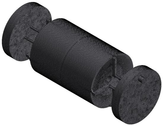
Figure 5.
Mesh for the computational domain.
As shown in Figure 6, the velocity stream and the convective heat transfer coefficients of asymmetric and symmetric structures under different inlet water velocities are simulated. Figure 6a and Figure 6b illustrate the velocity stream and the convective heat transfer coefficients with an inlet velocity of 1 m/s. Figure 6c and Figure 6d illustrate the velocity stream and the convective heat transfer coefficients with an inlet velocity of 4 m/s. The result shows that the maximum velocity in the asymmetric structure is higher than in the symmetric structure, while the symmetric structure has a more uniform velocity stream. The convective heat transfer coefficient of the symmetric structure is significantly higher than the asymmetric structure. The difference is more pronounced with the increase of inlet water velocity.
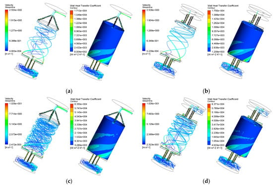
Figure 6.
Simulation in CFX between asymmetric and symmetric structures under different velocities: (a) asymmetric-1 m/s; (b) symmetric-1 m/s; (c) asymmetric-4 m/s; (d) symmetric-4 m/s.
The thermal load generated by the barrel conductor is mainly consumed through the inner surface. The contact surfaces of the barrel conductor with the upstream and downstream conductors in the integrated type are located on both the outer surface and the inner surface. The surface roughness of the entire barrel conductor is R30. The barrel conductor in the separated type pyro-breaker is designed to only contact other conductors on the outer surface. Therefore, changing the roughness of its inner surface will not affect the contact resistance. The influence of surface roughening on the convective heat transfer coefficient can also be simulated in CFX by changing the parameters of the surface conditions. Convective heat transfer coefficients with a surface roughness of R30 and R100 are simulated. As shown in Figure 7, although an increase in the surface roughness reduces the fluid velocity, the convective heat transfer coefficient is obviously improved.
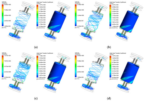
Figure 7.
Simulation in CFX under different surface roughness and velocities: (a) R30-1 m/s; (b) R100-1 m/s; (c) R30-4 m/s; (d) R100-4 m/s.
Table 6 shows the average calculated convective heat transfer coefficient of the cavity under different structural optimizations. The convective heat transfer coefficient of the symmetrical structure with a surface roughness of R100 and an inlet water velocity of 4 m/s can meet the demanding requirements of a 100 kA pyro-breaker, as calculated by ANSYS/Workbench.
Table 6.
The average calculated convective heat transfer coefficient of the cavity under different structural optimizations and inlet water velocities.
3.3. Experiments
To verify the feasibility of the convective heat transfer coefficient methods, the thermal–electric simulation of the CS with different structures and surface roughness are simulated in ANSYS/Workbench under a current of 40 kA and an inlet water velocity of 1 m/s. The environment temperature is set to 25 °C. The convective heat transfer coefficients are calculated by CFX. The results are shown in Table 4.
Three prototypes are manufactured to conduct the experiments to compare with the simulation results. To simplify the experiments, only the barrel conductor and related conductors are selected for the prototypes. All the prototypes are tested under the current of 40 kA for 1 h with an inlet water velocity of 1 m/s. The actual environment temperature is 23.4 °C. Thermal resistors are mounted on the barrel conductors.
3.4. Results and Discussion
The results of the experiments are shown in Figure 8. The rising speed and the steady value of the average measured temperature on the barrel conductor of the symmetrical structure are significantly lower than the asymmetrical structure. The temperature difference between a surface roughness of R30 (76.64 °C) and R100 is relatively smaller but has an obvious effect on the heat transfer enhancement. This indicates that the selected methods are feasible to enhance the convective heat transfer coefficient.
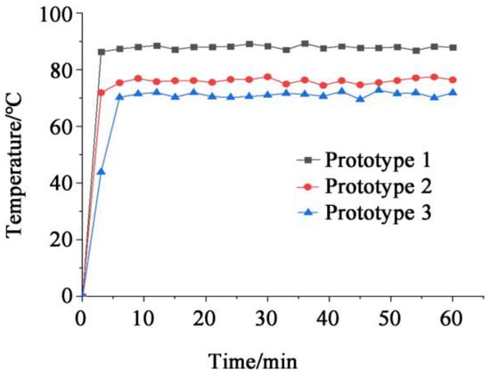
Figure 8.
Temperature curves of the barrel conductors with different structures and surface roughness.
As the average convective heat transfer coefficient of the cavity is unable to be measured, the calculated convective heat transfer coefficient of the cavity is verified by the comparison between the simulation and the experiment of the barrel conductor, as illustrated in Table 7. The temperature rise for different prototypes has been simulated with the calculated convective heat transfer coefficient of the cavity in ANSYS/Workbench. The measured temperature rises have good consistency with the simulated temperature rises in all three prototypes. For the asymmetrical structure, the difference in the temperature rise between the simulation and the experiments is larger than that in the symmetrical structure. This may be due to the uniformity of the velocity field becoming even more severe under non-ideal conditions, which, on the other hand, proves the advantage of a symmetrical structure in the water channels.
Table 7.
Comparison between simulation and experiment of the barrel conductor with different structures and surface roughness.
4. Conclusions
According to the recently proposed conceptual design of the China Fusion Engineering Test Reactor (CFETR), the current of the magnet power supply of the CFETR will reach a level of 100 kA. This demands the pyro-breaker in the quench protection system (QPS) has the same current capacity in a steady state. In the existing research, the bottleneck of the steady-state capacity of the pyro-breaker appears at the barrel conductor in the commutation section.
Based on the existing design and calculation, a separated type pyro-breaker is proposed in this paper. By studying the convective heat transfer enhancement methods, jet strengthening and surface roughening are considered to be the proper method to enhance the heat transfer for the presented breaker. A symmetrical water channel is designed for the new pyro-breaker to realize the jet strengthening. Computational fluid dynamics (CFD) is applied to calculate and compare the convective heat transfer coefficient of the inner cavity of the barrel conductor under different water channel structures and surface roughness values. Simulations and experiments are conducted on the three prototypes and the feasibility of the enhancement methods are verified. It can be concluded that the new pyro-breaker model with a symmetrical water channel structure and wall roughness of R100 can fulfil the demanding requirements of 100 kA current capacity. The proposed new model of the separated type pyro-breaker will be the design basis for further development of the pyro-breaker in CFETR. The symmetrisation of the water channel and the roughening of the heat exchange surface can also be used in other cooling water systems to achieve convective heat transfer enhancement.
Future work is required to improve the accuracy of the CFD model of the pyro-breaker by studying the turbulence model sensitivity. Additionally, only the fluid domain is discussed in this paper. Finally, the conductor should be included in the future model and the conjugate heat transfer should be considered to improve the efficiency and accuracy of the numerical calculation.
Author Contributions
Conceptualization, J.H. and J.L.; methodology, J.H.; validation, J.H., K.W. and J.L.; formal analysis, J.H.; writing—original draft preparation, J.H.; writing—review and editing, J.H., K.W. and J.L.; supervision, J.L. and K.W.; project administration, J.L.; funding acquisition, J.L. and K.W. All authors have read and agreed to the published version of the manuscript.
Funding
This research was funded by the National Key Research and Development Program of China, grant number 2017YFE0300504.
Acknowledgments
This work was supported by Shenzhen Clean Energy Research Institute. The authors would like to express gratitude to Honghao Ma of the University of Science and Technology of China and the students who assisted with the experiments.
Conflicts of Interest
The authors declare no conflict of interest.
References
- Zheng, J.; Song, Y.; Liu, X.; Lu, K.; Qin, J. Overview of the Design Status of the Superconducting Magnet System of the CFETR. IEEE Trans. Appl. Supercond. 2018, 28, 4204305. [Google Scholar] [CrossRef]
- Song, Y.; Wu, S.; Li, J.; Wan, B.; Wan, Y.; Fu, P.; Ye, M.; Liu, S.; Gao, X. Concept design of CFETR Tokamak machine. In Proceedings of the 2013 IEEE 25th Symposium on Fusion Engineering (SOFE), San Francisco, CA, USA, 10–14 June 2013; pp. 1–6. [Google Scholar]
- Fu, P.; Song, Z.Q.; Gao, G.; Tang, L.J.; Wu, Y.B.; Wang, L.S.; Liang. X.Y. Quench protection of the poloidal field superconducting coil system for the EAST tokamak. Nucl. Fusion. 2006, 46, S85. [Google Scholar] [CrossRef]
- Manzuk, M.; Avanesov, S.; Roshal, A.; Bestuzhev, K.; Nesterenko, A.; Volkov, S. The 70 kA pyrobreaker for ITER magnet back-up protection. Fusion Eng. Des. 2013, 88, 1537–1540. [Google Scholar] [CrossRef]
- Rummel, T.; Gaupp, O.; Lochner, G.; Sapper, J. Quench protection for the superconducting magnet system of WENDELSTEIN 7-X. IEEE Trans. Appl. Supercond. 2002, 12, 1382. [Google Scholar] [CrossRef]
- Barabaschi1, P.; Kamada, Y.; Shirai, H. Progress of the JT-60SA project. Nucl. Fusion. 2019, 59, 112005. [Google Scholar] [CrossRef]
- TASSONE, A.; Caruso, G.; Giannetti, F.; Nevo, A. MHD mixed convection flow in the WCLL: Heat transfer analysis and cooling system optimization. Fusion Eng. Des. 2019, 146, 809–813. [Google Scholar] [CrossRef] [Green Version]
- Miyoshi, Y.; Aoki, A.; Hiwatari, R.; Someya, Y.; Sakamoto, Y.; Tobita, K. Cooling water system design of Japan’s DEMO for fusion power production. Fusion Eng. Des. 2018, 126, 110–115. [Google Scholar] [CrossRef]
- Bianco, V.; Buonomo, B.; Pasqua, A.; Manca, O. Heat transfer enhancement of laminar impinging slot jets by nanofluids and metal foams. Therm. Sci. Eng. Prog. 2021, 22, 100860. [Google Scholar] [CrossRef]
- Kushchev, L.A.; Nikulin, Y.N.; Alifanova, A.I. Modern Methods of Investigation of Heat Transfer Enhancement in Shell-and-Tube Heat Exchangers. In Proceedings of the 2019 International Science and Technology Conference, Vladivostok, Russia, 1–4 October 2019; pp. 1–5. [Google Scholar] [CrossRef]
- Jeon, S.; Son, C. Comparative Numerical Study of the Influence of Film Hole Location of Ribbed Cooling Channel on Internal and External Heat Transfer. Energies 2021, 14, 4689. [Google Scholar] [CrossRef]
- Jasinski, P.B. Numerical Study of Heat Transfer Intensification in a Circular Tube Using a Thin, Radiation-Absorbing Insert. Part 1: Thermo-Hydraulic Characteristics. Energies 2021, 14, 4596. [Google Scholar] [CrossRef]
- Jasinski, P.B. Numerical Study of Heat Transfer Intensification in a Circular Tube Using a Thin, Radiation-Absorbing Insert. Part 2: Thermal Performance. Energies 2021, 14, 4533. [Google Scholar] [CrossRef]
- Cheng, D.; Wang, W.; Deng, H.; Shi, B.; Han, J.; Yang, J.; Wang, H. The Numerical Simulation for the Heat Transfer Enhancement Experiments of the HCCB-TBM First Wall. IEEE Trans. Plasma Sci. 2018, 46, 1458–1465. [Google Scholar] [CrossRef]
- He, J.; Song, Z.; Tang, C.; Fu, P.; Zhang, J. Study of contact resistance in the design of a pyro-breaker applied in superconducting fusion facility. Plasma Sci. Technol. 2019, 21, 065602. [Google Scholar] [CrossRef]
- He, J.; Song, Z.; Tang, C.; Fu, P.; Ye, J. Designing of cooling water system for a pyro-breaker utilized in superconductive fusion facility. Fusion Eng. Des. 2019, 148, 111294. [Google Scholar] [CrossRef]
- Burmeister, L.C. Convective Heat Transfer; John Wiley & Sons: New York, NY, USA, 1983; Chapter 11; p. 497. [Google Scholar]
- Lee, H.H. Finite Element Simulations with ANSYS Workbench 15; SDC Publications: Mission, KS, USA, 2014. [Google Scholar]
- ANSYS CFX-Solver Theory Guide, ANSYS, Inc. Available online: http://www.ansys.com (accessed on 12 October 2021).
Publisher’s Note: MDPI stays neutral with regard to jurisdictional claims in published maps and institutional affiliations. |
© 2021 by the authors. Licensee MDPI, Basel, Switzerland. This article is an open access article distributed under the terms and conditions of the Creative Commons Attribution (CC BY) license (https://creativecommons.org/licenses/by/4.0/).