Abstract
Many high speed applications employ a surface permanent magnet (PM) machine topology with a retaining sleeve due to its robustness and ability to achieve high overall peripheral speeds as well as efficiencies. One often overlooked feature in the mechanical design of such machines, which has not achieved sufficient attention to date is the anisotropic thermal expansion of rare earth magnets, the degree of which varies for different magnet technologies. This paper investigates the effects of the aforementioned on the mechanical design of a high speed PM spindle machine with NdFeB magnets. The maximum allowable interference is found to be limited by the working temperature of the magnets while the minimum required interference is increased due to their anisotropic thermal expansion. Based on this, appropriate conditions are formulated to integrate a Neodymium Iron Boron (NdFeB) PM in high speed rotors. These modifications considering the shaft together with the magnet anisotropic thermal expansion are included in a proposed rotor design and validated using simulations in ANSYS mechanical environment.
1. Introduction
High speed electrical machines have increased their market uptake in applications like microturbines, turbochargers, turbomolecular pumps and gas compressors [1]. These applications employ a turbine and/or compressor whose rated power ranges from a few kWs up to few hundred kWs. In this range, a higher system efficiency is obtained by operating the turbine or compressor at a very high speed [2] and consequently the electrical machine coupled to it. High speed machines are generally surface mount permanent magnet synchronous machine (PMSM), solid rotor induction motor (IM) or switched reluctance motor (SRM) [1]. The PMSMs have better efficiency compared to IM and SRM [2]. However, their maximum operating temperature is limited by the use of PM [2]. Samarium Cobalt (SmCo) magnets are specially used in thermally aggressive environments due to their high temperature withstand ability (>350 °C) [3]. Furthermore, their magnetic properties are more stable [4] with temperature which helps in reducing the overall converter rating. NdFeB magnets have higher energy densities, and their high temperature capabilities have been steadily improving, with grades having a maximum temperature of +230 °C commercially available [3]. There are some specific high speed applications like spindle drives and flywheel energy storage where the operating temperature is low and response time is a critical parameter which should be reduced to the minimum possible value [5]. The acceleration and deceleration of these drives depends on inertia of the rotor. Hence, acceleration can be improved by using PMs having a higher field strength. The demand for a high field strength at low operating temperature favours the use of NdFeB PMs.
The metallic retaining sleeves and rare earth PMs are electrically conductive. This could result in a significant amount of eddy current being induced at high frequency operation. Hence, a majority of research reported in the field of high speed PMSM are dedicated to the reduction of eddy current losses in the rotor. This is accomplished by techniques such as changing the material of the retaining sleeve [6], using a conductive shield of copper between retaining sleeve and PM [7], segmenting the PM [8] and axial grooving or segmenting the retaining sleeve [9]. However, to date, there are very few comprehensive literature guidelines on the mechanical design of high speed PMSM.
Rare earth PMs are manufactured by bonding or sintering the magnet alloy into the required shape and size. This results in PMs having a low tensile strength and high compressive strength [10]. Most high speed surface mount PMSMs typically have a non magnetic retaining sleeve and a cylindrical PM. The dimensions of the retaining sleeve and PM are selected to accomplish a shrink fit between them during the fabrication process. The interference caused by shrink fit should maintain the PM in a state of compression for its entire range of operation. Conventional method of estimating interference involves stress analysis due to shrink fit, temperature and speed. The temperature considered here is the maximum estimated operating point resulting from rotor losses [11] and not the brief value attained by PM upon interacting with the heated retaining sleeve during fabrication. This transient rise in temperature will impose an upper limit over the range of values considered suitable for estimating interference.
Through-shaft rotor of a high speed PMSM is shown in Figure 1a. The optimal value of interference is conventionally obtained considering only the retaining sleeve and PM [10,12,13]. However, in case of a through-shaft rotor this could result in an erroneous structural design as the shaft prevents the PM from free contraction during shrink fit. Therefore, the shaft should be considered in the analysis of shrink fit. Furthermore, if the retaining sleeve is made of carbon fibre it exhibits anisotropic behaviour, hence, this anisotropic nature of carbon fibre should be included in the analysis of interference fit [14,15,16]. Typically, in existing literature axisymmetric shrink fit analysis is performed considering isotropic thermal expansion of PM if a metallic retaining sleeve is used [10,12,17]. In contrast, both NdFeB and SmCo PMs exhibit anisotropic thermal expansion [18,19]. Furthermore, the anisotropic nature of the magnets varies between grades [18,20]. This necessitates structural analysis in the transverse plane considering anisotropic thermal expansion of PM. Finally, the shaft key, used for holding PM onto the shaft is avoided in high speed machines to prevent asymmetry. Hence, the contact pressure between each adjacent pair is designed to incorporate appropriate torque transfer capability while simultaneously ensuring sufficient structural rigidity of the rotor.
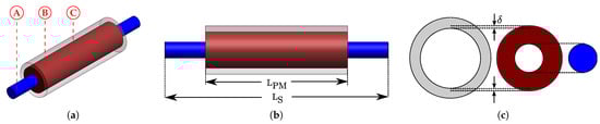
Figure 1.
Through-shaft rotor configuration (a) Isometric view showing its shaft (A), PM (B) and retaining sleeve (C) (b) Axial view showing length of PM () and shaft () (c) Conventionally established relationship between radial dimensions.
This paper is organized as follows. The anisotropic thermal expansion in rare earth PMs is explained in Section 2. Section 3 describes the methodology followed while selecting various components in the rotor. The electromagnetic design of a through-shaft rotor is explained in Section 4. Interference is estimated in Section 5 considering only the retaining sleeve and PM. The modification required in shrink fit analysis due to anisotropic thermal expansion is proposed in Section 6. The rotordynamic analysis is given in Section 7. Finally, the outcome of the structural analysis with inclusion of anisotropic thermal expansion is presented in Section 8.
2. Anisotropic Thermal Expansion in Sintered Rare Earth PMs
The crystal structure representation of a sintered anisotropic PM is shown in Figure 2a. The c-axis represents the axis of easy magnetization while the a-axis represent the axis of hard magnetization. Typically, for rare-earth magnets, the coefficient of thermal expansion is provided in both the parallel and perpendicular directions to the c-axis by the manufacturers. The c-axis and a-axis for a diametrically magnetized PM can be easily identified by comparing Figure 2b with Figure 2a. For NdFeB magnets, the diametrically magnetized PM changes from circular to elliptical in shape as shown in Figure 2c. Elliptical shape results due to the expansion of PM along y-axis and contraction along x- and z-axis caused by a rise in temperature. The diametrically magnetized PMs are the type of PMs which are commonly incorporated in 2 pole high speed machines to achieve a sinusoidal flux distribution in the airgap. Therefore, anisotropic thermal expansion should be considered while designing the machine in contrast to conventionally used (in literature to date) isotropic analysis.
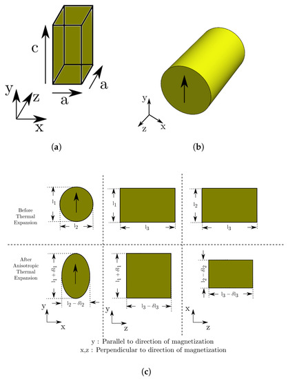
Figure 2.
Anisotropic PMs (a) Crystal structure (b) Diametrically magnetized PM (c) Dimensional changes due to thermal expansion.
3. Material Selection and Design Specification of PMSM with Through-Shaft Rotor
Material selection is the foremost phase in designing a motor. Meticulous investigation at this stage aids the designer in identifying the maximum permissible temperature during fabrication and operation. The thermal stress imposed on the magnet during fabrication is much higher compared to the normal working limit. The rotor comprises of three components, namely, PM, retaining sleeve and shaft. The retaining sleeve and shaft are typically composed of non magnetic material while the magnet belongs to the rare earth family of PMs. Selection of material suitable for sleeve and PM is discussed below.
3.1. Retaining Sleeve
The thickness of the retaining sleeve adds to the airgap and in turn increases the apparent airgap encountered by the PM. The sleeve thickness can be reduced by using a material which exhibits higher yield strength. The coefficient of thermal expansion (CTE) is a measure of maximum interference realized with a material for a definite rise in temperature. Conventionally, the shrink fit between PM and retaining sleeve is achieved by cooling the former and heating the latter. However, on cooling, NdFeB PM expands in the perpendicular direction due to its negative CTE. Therefore, cooling the PM does not aid the fabrication process. Hence, the interference is more favourably established by only heating the retaining sleeve. The ultimate tensile strength and CTE of the commonly used materials in retaining sleeve like Inconel 718 and Titanium alloy are shown in Table 1a. After examining the fore mentioned qualities, Inconel 718 with higher tensile strength and thermal expansion is selected for the retaining sleeve.

Table 1.
Properties of materials suitable for (a) Retaining sleeve [21] and (b) Rare earth PMs [18,19].
3.2. Permanent Magnet
The thermal and mechanical properties pertaining to typical grades of the major classes of rare earth PMs are listed in Table 1b. The tensile and compressive strength of NdFeB magnets are higher than that of SmCo PMs. This shows that the former is mechanically stronger and establishes it as a suitable candidate for being employed in a high speed machine. Nevertheless, the common argument cited against NdFeB PM is its poor thermal stability. Two PMs, one from each group, with comparable maximum operating temperature are chosen for evaluation. The remanence () and maximum energy product () are higher for NdFeB and in support of choosing it while the temperature coefficient of remanence (TCR) provides a hindrance. However, TCR is not a suitable parameter to compare PMs unless their maximum operating temperature is considered. The maximum worst case operating temperature in our application is curtailed to 61 °C based on the thermal analysis presented in Section 4.2. Therefore, it is essential to compare at the maximum operating temperature. The remanence of NdFeB is higher compared with SmCo magnet even at 60 °C. This supports the use of NdFeB magnets.
3.3. Rating
The motor ratings for this case study are drawn from a high speed motorized spindle requirement as given in Table 2a. The dimensional restrictions on the high speed motor are listed in Table 2b. After analyzing the demands, surface mount PMSM with a retaining sleeve is selected to realize the wide ranging requirements imposed on the motor like ultra high speed, compactness and high efficiency.
Table 2.
Design specification (a) Motor rating (b) Dimensional restrictions.
4. Design
4.1. Electromagnetic Design
The electromagnetic design of a PMSM with through-shaft rotor is performed considering the dimensional restrictions imposed on the machine, specifically, the stator outer diameter and the rotor length. The maximum rotor length, specified in Table 2b, corresponds to the length of PM () and not the overall rotor length (), as depicted in Figure 1b Traditionally, the stack length of stator is kept longer than to reduce the end effects. Nevertheless, the present design considers both to be equal. In addition, a hollow cylindrical PM with diametrical magnetization is used in this rotor to achieve sinusoidal flux density distribution in the airgap.
As the switching frequency required at high speeds is in the order of few kHz even in case of a two pole machine, core loss is significant. It can be reduced by decreasing the operating flux density in the stator. But, selection of stator material with a high value of saturation flux density, offers sufficient slot area to accommodate and cool the conductors. Based on these observations, Vacoflux 48 with a high saturation flux density of 2.1 T and simultaneously a low core loss of 199 W/kg is selected for the stator laminations. The core loss value is given at 2 T with an excitation frequency of 2 kHz.
The dimensions of the machine resulting from empirical equations are listed in Table 3. The analytical design is validated using 2-Dimensional MagNet Finite Element Analysis (FEA) package. The maximum flux density in the stator core is less than 2.1 T as shown in Figure 3a. The output torque is plotted in Figure 3c by exciting the stator coils with both sinusoidal and quasi square wave currents as given in Figure 3b. The value of output torque shown in Figure 3c matches closely with the demanded value and its torque ripple is around 15%. All these aspects ascertain the validity of the designed motors.
Table 3.
Motor dimensions.
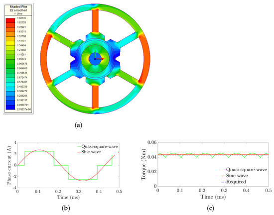
Figure 3.
FEA simulation results showing (a) Flux density distribution with quasi-square-wave (b) Applied phase current (c) Output torque.
4.2. Thermal Analysis
The temperature distribution and peak operational temperature in the rotor are critical for estimating the required interference and conducting a successful mechanical design. A coupled electromagnetic and thermal analysis is performed using MagNet and ThermNet FEA packages to obtain the temperature distribution in the rotor. Losses are presented in Table 4 for both sinusoidal and quasi-square-wave excitations to establish a worst-case rotor temperature value. As expected quasi-square-wave rsults in more eddy current loss in the retaining sleeve and PM due to its higher harmonic content as shown in Table 4. The thermal conductivity and specific heat capacity of various materials used in thermal analysis is given in Table 5.
Table 4.
Losses due to sinusoidal and quasi square wave excitation.
Table 5.
Thermal Coefficients.
A water jacket cooling is assumed with an ambient temperature of 30 °C. The temperature distribution in the machine is shown in Figure 4, with the maximum temperature in the rotor being nearly 61 °C. Hence, performing shrink fit analysis at a temperature of 100 °C will ascertain the rotor with sufficient structural integrity considering other unaccounted losses in the machine.
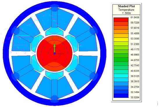
Figure 4.
Temperature distribution.
5. Shrink Fit Analysis
The interference established by shrink fitting the retaining sleeve on to PM should withstand the effects of speed and temperature. The dimensional relationship existing along the radial direction is illustrated in Figure 1c. The inner radius of retaining sleeve is always less than the outer radius of PM by the demanded interference (). In addition, the outer radius of shaft is made equal to the inner radius of PM to enable smooth sliding of the shaft through the PM before shrink fitting the retaining sleeve.
The shrink fit is evaluated at 170 krpm (≈1.2 × maximum speed) and 100 °C to ensure sufficient safety margin at the maximum operating point. The properties of Inconel 718 and NdFeB PM are shown in Table 6. The maximum allowable tensile and compressive stresses are obtained considering the factor of safety as 1.5. A search range of 1 to 30 m is selected to identify the most favourable interference. The shaft is not considered in this analysis. Initially, the interference is calculated without imposing the tensile limits of Inconel 718 and the results are plotted in Figure 5a. The assigned interference represent the value established during fabrication. The interference is reduced on including the effect of speed and temperature. This decrease in resulting interference is illustrated in Figure 5a with an assigned interference of 10 m. Radial deformation in PM due to change in temperature is maximum in the directions parallel and perpendicular to magnetization as shown in Figure 5b. The conventional analysis is performed considering isotropic thermal expansion using CTE in the parallel direction. However, the required value of minimum interference is found to increase if we consider the thermal expansion in perpendicular direction. This demonstrates the significance of considering anisotropic thermal expansion in NdFeB PM while estimating the interference.
Table 6.
Properties of sleeve [21] and PM [18].
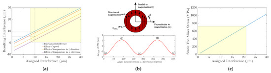
Figure 5.
Structural analysis (a) Without considering stress limits (b) Radial expansion at outer boundary of PM at 100 °C (c) Considering only static stress.
Figure 5c and Figure 6a,b are obtained by including the stress limits of Inconel 718 and NdFeB PM in our analysis. The favourable zone of interference is reduced on including the effect of speed (Figure 6a) as compared to its static value (Figure 5c). The increase in minimum interference is a result of sleeve disengaging from the assembly while the decrease in maximum interference is due to the additional contribution of stress from centrifugal force to the shrink fit assembly. Figure 6b is obtained by including the effects of shrink fit, speed and temperature to the mechanical stress. The increase in lower limit is again due to the disintegration of assembly. However, thermal expansion decreases the stress and in turn increases the upper limit on the favorable interference. This indicates the importance of considering all the effects in stages before arriving at the favorable set of interference.
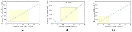
Figure 6.
Structural analysis showing (a) Dynamic stress including the effect of speed (b) Dynamic stress including the effect of speed and temperature (c) Thermal expansion of sleeve.
The rotor fabrication is initiated by heating the retaining sleeve. Therefore, the PM interacts with a retaining sleeve at high temperature. Permanent demagnetization can be prevented by restricting sleeve temperature below maximum working temperature of PM. NdFeB PM has a maximum working temperature of 200 °C. This indirectly restricts the value of maximum possible interference which can be obtained by using Inconel 718 as retaining sleeve to 10 m as shown in Figure 6c. Taking all the above mentioned factors into account, the favourable range of interference is found to be 8 to 10 m as identified in Table 7.
Table 7.
Favourable range of interference.
6. Structural Analysis of Rotor
The highest favorable value of interference i.e., 10 m is selected to ensure maximal structural integrity in the rotor. The structural FEA is performed to evaluate the rigidity of rotor. Deformation, radial stress (), circumferential or tangential stress () and Von-Mises stress () are the outputs of structural analysis. is used to identify the state of a body. It is positive for tension and negative for compression. exerts contact pressure to hold the components together. It is used as a parameter to ensure perfect torque transfer in the absence of a rotor key. is a scalar quantity used to identify the yield limit of a material. The value of should be restricted below the allowable stress limits to prevent plastic deformation. The anisotropic thermal expansion establishes quarter symmetry in the rotor. Therefore, a quadrant of the cylindrical rotor is subjected to structural FEM analysis.
The through-shaft rotor is simulated in ANSYS FEA considering only the retaining sleeve and PM. Frictionless support is applied as the boundary condition to impose the inherent quarter symmetry in rotor structure, as shown in Figure 7a. The other conditions, which are included in the simulation, are speed and temperature of 170 krpm and 100 °C respectively. Figure 7b implies that the maximum value of is much less than 735 MPa in the retaining sleeve. Figure 7c validates that the PM is in compression while the sleeve is in a state of tension without the shaft and considering anisotropic thermal expansion. These results corroborates the choice of 10 m as the assigned interference. However, further studies with the presence of shaft is instigated to gain a better insight in the evaluation of the required shrink fit.
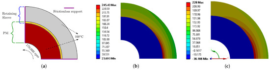
Figure 7.
Structural FEA analysis showing (a) Boundary condition applied in simulation (b) Von-Mises stress without shaft and anisotropic CTE (c) Circumferential stress without shaft and anisotropic CTE.
6.1. Including the Presence of Shaft
6.1.1. FEM Analysis
Unlike the retaining sleeve, the shaft does not share an interference fit with PM. It holds on to PM by the contact pressure generated at the shaft-PM interface due to the shrink fit established between sleeve and PM. Shaft is fabricated from Inconel 718 to ensure high stiffness. Generally, axisymmetric analysis is performed considering isotropic thermal expansion. Though the PM has anisotropic thermal expansion, initially isotropic CTE is considered to identify the variation in developed stress due to the presence of shaft. Mesh sensitivity analysis is performed to ascertain the validity of FEA results. The circumferential stress resulting due to shrink fit analysis including the shaft is shown in Figure 8a for isotropic thermal expansion in PM. The variation of circumferential stress along the radial direction.
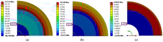
Figure 8.
Structural FEA analysis showing (a) Circumferential stress with shaft and isotropic CTE (b) Circumferential stress with shaft reduced by 1 m and isotropic CTE (c) Static deformation without shaft.
6.1.2. Analytical Model
Analytical modelling of interference is performed to validate the results obtained through FEA. Multilayer interference analysis [22] is considered to model interference between shaft-PM and PM-Sleeve. The rotor dimensions, namely a, b and c as shown in Figure 9a are chosen for the shaft-PM interface, PM-sleeve interface and the outer radius of sleeve respectively. The radial stress acting on various components are represented in Figure 9b–d after considering a contact pressure of and at the shaft-PM and PM-sleeve interface respectively. The stress analysis at the shaft-PM and PM-sleeve interface results in (1)–(3) and (4)–(6) respectively. , and represent the Young’s modulus of shaft, PM and sleeve respectively. Similarly, , and represent the Poisson’s ratio of shaft, PM and sleeve respectively. and are the interference at the shaft-PM and PM-sleeve interfaces respectively.
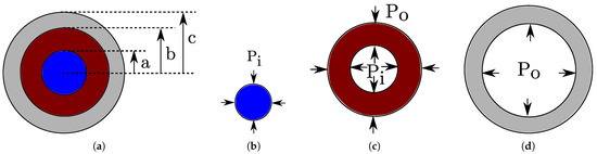
Figure 9.
Model for analytical evaluation showing (a) Rotor dimension (b) Shaft (c) PM (d) Sleeve.
- Shaft-PM interface
- PM-Sleeve interface
- Radial Stress
- -
- Shaft:
- -
- Permanent Magnet
- -
- Sleeve
- Circumferential Stress
- -
- Shaft:
- -
- Permanent Magnet
- -
- Sleeve
The effect of centrifugal force on radial and circumferential stress at a point r in a cylinder are represented by and , and calculated using (15)–(16) respectively. Both centrifugal force and thermal expansion alters the radius of shaft, PM and sleeve. and represent the radial change in dimension at a point r in a cylinder due to centrifugal and thermal effects respectively. This variation in radial dimension due to centrifugal and thermal effects changes the interference at the shaft-PM and PM-sleeve interface. Therefore, this is considered in the analytical modelling by changing and in Equations (1) and (4) based on (17) and (18). Equations (15)–(18) are generalized equation of a hollow cylinder where , , , , , and represent Young’s modulus, Poisson’s ratio, inner radius, outer radius, point of analysis, density and speed of rotation respectively. k = 1, 2 and 3 for shaft, PM and sleeve respectively. , and represent the coefficient of thermal expansion for the material used for shaft, PM and sleeve respectively. The change is temperature from ambient is given in (18) by . Based on the analyzed part of the rotor, these values are selected following Table 8.
Table 8. Parameters for analytical equations. - Effect of centrifugal force
- Effect of temperature
The analytical results obtained using (1)–(18) with and as 0 and 10 m respectively are presented in Table 9. The FEA results highlighting the stress at the interface are shown in Figure 10a–c. These results are presented in numerical form in Table 10. On comparing the values in Table 9 with Table 10, the analytical and FEA results are found to be very close. This validates the FEA results (Figure 11).
Table 9.
Analytical Results.
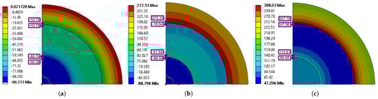
Figure 10.
FEA results showing (a) Radial stress (b) Tangential stress (c) Von Mises stress.
Table 10.
FEA Results.
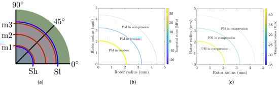
Figure 11.
(a) Rotor structure showing the contours along which various results will be analyzed (0°: perpendicular to magnetization, 45°: 45° with respect to the perpendicular direction of magnetization, 90°: parallel to magnetization, m1, m2 and m3: Inner, middle and outer boundary of PM, sh: outer boundary of shaft and Sl: inner boundary of sleeve) (b) Circumferential stress along m1, m2 and m3 considering shaft and isotropic expansion (c) Circumferential stress along m1, m2 and m3 considering shaft reduced by 1 m and isotropic expansion.
6.2. Design Changes to Reduce Tensile Stress
The restriction offered by shaft is the cause of tensile stress in PM. Figure 8c shows the free compression of PM due to shrink fit in the absence of shaft. The radial contraction at the inner circumference of PM solely due to static shrink fit is 2.5 m. The presence of shaft prevents free contraction of PM and in turn exerts force in the opposite direction. The CTE of shaft is much higher compared to that of NdFeB PM. During thermal expansion, this increases the magnitude of opposing force and in turn dominates the compressive force offered by the retaining sleeve. Thus the net force acting on PM is tensile in nature. The opposing force can be decreased by reducing the outer diameter of shaft. The gap created between shaft and PM increases the zone for free contraction of PM. However, the outer diameter cannot be reduced considerably as this might detach the shaft from PM.
The contact pressure holds the permanent magnet onto the shaft and enables perfect torque transfer. The maximum permissible torque transfer by shrink fit is estimated using (19),
where, T and a are rated torque and radius of shaft respectively. is the axial length of PM as shown in Figure 1b. The coefficient of friction is taken as 0.2. Using (19), the contact pressure () at PM-shaft interface should be greater than 0.25 MPa for rated torque transfer.
The radius of the shaft is estimated using (1)–(18) by considering the following steady state and transient conditions of the machine:
- Speed: 0 to 170,000 rpm
- Temperature: 25 to 100 °C
- Maximum temperature difference between sleeve and PM: 10 °C
- Maximum temperature difference between PM and shaft: 10 °C
- a for PM and shaft < 0
- a for PM and shaft > 5 MPa (Considering a multiplication factor of 20 on )
Based on the above conditions, the radius of the shaft can be reduced within a range of 0.8 to 1.1 m. From this, 1 m is chosen for FEA analysis. Figure 8b shows the variation in circumferential stress after the shaft diameter is reduced by 1 m. The PM is completely in compression and the maximum tangential stress on the PM has reduced to −5 MPa from 41.5 MPa.
6.3. Anisotropic Thermal Expansion
All sintered magnets are anisotropic in nature. Hence, it is essential to consider anisotropic thermal expansion during structural analysis of rotor. Three commercially available PMs with different CTE are considered to study the effect of anisotropic thermal expansion of PM on the rigidity of the rotor. The thermal expansion coefficients of these PMs are listed in Table 11. Isotropic expansion of these PMs are performed initially to establish the necessity of anisotropic thermal expansion. The variation in tangential stress for type I, II and III PM are shown in Figure 12a, Figure 12b and Figure 12c respectively. Based on these results it can be inferred that type I and II PMs are in tension while type III PM is in compression even after including the presence of shaft.
Table 11.
Thermal properties of PMs.
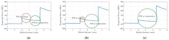
Figure 12.
FEM results showing variation in tangential stress with isotropic thermal expansion for (a) Type I PM (b) Type II PM (c) Type III PM.
Anisotropic thermal expansion is performed subsequently and results are shown in Figure 13a–c. For better visualization, the graphical representation of the same results are given in Figure 14a–c for type I, II and III PM respectively. The angles represented in Figure 14a–c are with respect to the perpendicular direction of magnetization in the anticlockwise direction as shown in Figure 11a.
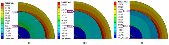
Figure 13.
FEM results showing tangential stress without reduction in shaft radius for (a) Type I PM (b) Type II (c) Type III PM.
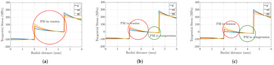
Figure 14.
FEM results showing the variation in tangential stress with anisotropic expansion for (a) Type I PM (b) Type II PM (c) Type III PM.
The PM is in tension for type I, II and III PM unlike the result predicted by considering isotropic thermal expansion. The maximum tensile stress is above 50 MPa is all three cases. This value is found to occur at the inner radius of PM along the axis parallel to direction of magnetization. Similar to isotropic thermal expansion, the influence of the radius of shaft during anisotropic thermal expansion is studied by reducing it by 1 m. The FEM results with reduced outer diameter of shaft are shown in Figure 15a–c. It can be seen that the maximum tensile stress has significantly reduced by reducing the diameter of shaft. However, only type II and III PM exhibit maximum tensile stress below 50 MPa. Thus, anisotropic CTE influences the type of PM which can be employed in design. Nevertheless, 1 m is below the achievable manufacturing limits and also not practically feasible. This necessitates the need to identify alternative methods which are practically implementable.
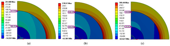
Figure 15.
FEM results showing tangential stress with shaft radius reduced by 1 m for (a) Type I PM (b) Type II PM (c) Type III PM.
6.4. Material with Lower CTE: Titanium Shaft
As previously mentioned in Section 3, the higher CTE of Inconel enables increased interference fit and thereby favours its selection over titanium for the retaining sleeve. However, the same property of Inconel is found to limit its application for the shaft as elaborately discussed in Section 6. The possibility of replacing the Inconel shaft with a material of lower CTE i.e., titanium is studied in this section. The material properties of titanium like density, Young’s modulus and Poisson’s ratio are 4400 kg/m, 97 GPa and 0.34, respectively. The FEM results with titanium shaft are shown in Figure 16a–c. The maximum tensile stress is below 50 MPa for type II and II PMs. This is achieved without reducing the outer diameter of the shaft. Consequently, a material with lower CTE is identified as the ideal choice for the shaft.
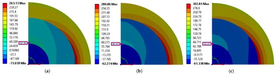
Figure 16.
FEM results showing tangential stress with titanium shaft for (a) Type I PM (b) Type II PM (c) Type III PM.
7. Rotordynamic Analysis
The rotordynamic analysis is performed to avoid mechanical resonance below the maximum operating speed of the machine. The critical frequency of the rotor is evaluated by incorporating a bearing stiffness of 50,000 N/mm. The first and second critical speeds are found to be 225,840 and 660,060 respectively. The first critical speed is much higher than the maximum operating speed. Therefore, the rotor does not undergo any mechanical resonance in the operating speed range. The deformation of the rotor in its first critical speed is shown in Figure 17.
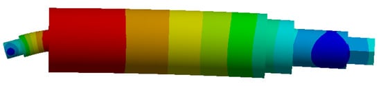
Figure 17.
Deformation at the first critical speed.
8. Conclusions
In this paper, effect of anisotropic thermal expansion of NdFeB PM is identified and taken into account for interference calculation of a high speed PMSM. A PMSM with through-shaft rotor is designed and its structural integrity is validated using ANSYS FEA. In addition, analytical formulation based on multilayer interference analysis is provided to model both shaft-PM and PM-sleeve interface simultaneously. The results of analytical formulation is found to match quite closely with the FEA analysis. The key observations are as follows:
- The minimum interference required between the retaining sleeve and PM increases due to anisotropic thermal expansion.
- The maximum interference is limited by the working temperature of NdFeB PM.
- The absence of shaft enables free internal deformation of the PM. This ensures that the PM is in compression due to the interference at the PM-sleeve interface. However, the presence of shaft restricts the free internal deformation of the PM and results in tensile stress. Therefore, it is crucial to account for the presence of shaft while estimating the interference.
- Increased tensile stress is found to occur on the PM at shaft-PM interface. This is because of restricted internal deformation of PM due to the presence of shaft. Consequently, the rotor should be designed with reduced outer diameter of shaft and considering anisotropic thermal expansion in NdFeB PM.
- A reduction of 1 m is required on the outer diameter of the shaft to prevent excessive tensile stress in the PM. However, this value is difficult to be realized with the current manufacturing technologies. Therefore, using a material with lower CTE for the shaft is established as the practically feasible solution.
- The CTE of NdFeB magnets vary from one manufacturer to the other. CTE is found to play a dominant role in the value of tensile stress experience by the PM. Therefore, the grade of PM should be selected only after analyzing their CTE.
Author Contributions
Conceptualization, R.K. and G.V.; methodology, R.K. and A.L.R.; software, G.V.; validation, R.K., G.V. and A.L.R.; formal analysis, G.V.; investigation, D.G.; resources, G.V., D.G. and C.G.; data curation, D.G.; writing—original draft preparation, R.K.; writing—review and editing, G.V. and A.L.R.; visualization, C.G.; supervision, G.V.; project administration, B.G.F.; funding acquisition, G.V. and C.G. All authors have read and agreed to the published version of the manuscript.
Funding
This research received no external funding.
Conflicts of Interest
The authors declare no conflict of interest.
References
- Gerada, D.; Mebarki, A.; Brown, N.L.; Gerada, C.; Cavagnino, A.; Boglietti, A. High-Speed Electrical Machines: Technologies, Trends, and Developments. IEEE Trans. Ind. Electron. 2014, 61, 2946–2959. [Google Scholar] [CrossRef]
- Gerada, D.; Huang, X.; Zhang, C.; Zhang, H.; Zhang, X.; Gerada, C. Electrical Machines for Automotive Electrically Assisted Turbocharging. IEEE/ASME Trans. Mechatron. 2018, 23, 2054–2065. [Google Scholar] [CrossRef]
- Bartolo, J.B.; Zhang, H.; Gerada, D.; de Lillo, L.; Gerada, C. High speed electrical generators, application, materials and design. In Proceedings of the 2013 IEEE Workshop on Electrical Machines Design, Control and Diagnosis (WEMDCD), Paris, France, 11–12 March 2013; pp. 47–59. [Google Scholar]
- An, S.; Ma, Z.; Li, W.; Zhang, H.; Yin, T. Magnetic properties of anisotropic bonded NdFeB/SmCo permanent magnets. AIP Adv. 2019, 9, 125146. [Google Scholar] [CrossRef]
- Mazurkiewicz, J. Machine Design, Automation and IIOT. 1 July 2000. Available online: www.machinedesign.com/auto-mation-iiot/article/21828654/selecting-highperformance-ac-spindle-motors (accessed on 6 August 2018).
- Li, W.; Qiu, H.; Zhang, X.; Cao, J.; Yi, R. Analyses on Electromagnetic and Temperature Fields of Superhigh-Speed Perma-nent-Magnet Generator with Different Sleeve Materials. IEEE Trans. Ind. Electron. 2014, 61, 3056–3063. [Google Scholar] [CrossRef]
- Fang, H.; Qu, R.; Li, J.; Song, B. Rotor eddy-current loss minimization in high-speed PMSMs. In Proceedings of the 2016 IEEE Energy Conversion Congress Exposition (ECCE), Milwaukee, WI, USA, 18–22 September 2016; pp. 1–8. [Google Scholar] [CrossRef]
- Fang, H.; Qu, R.; Li, J.; Zheng, P.; Fan, X. Rotor design for a high-speed high-power permanent-magnet synchronous machine. In Proceedings of the 2015 IEEE Energy Conversion Congress Exposition (ECCE), Montreal, QC, Canada, 20–24 September 2015; pp. 4405–4412. [Google Scholar]
- Shen, J.-X.; Hao, H.; Jin, M.-J.; Yuan, C. Reduction of Rotor Eddy Current Loss in High Speed PM Brushless Machines by Grooving Retaining Sleeve. IEEE Trans. Magn. 2013, 49, 3973–3976. [Google Scholar] [CrossRef]
- Wang, T.; Wang, F.; Bai, H.; Xing, J. Optimization design of rotor structure for high speed permanent magnet machines. In Proceedings of the 2007 International Conference on Electrical Machines and Systems (ICEMS), Seoul, Korea, 8–11 October 2007; pp. 1438–1442. [Google Scholar]
- Zhou, F.; Shen, J.; Fei, W.; Lin, R. Study of Retaining Sleeve and Conductive Shield and Their Influence on Rotor Loss in High-Speed PM BLDC Motors. IEEE Trans. Magn. 2006, 42, 3398–3400. [Google Scholar] [CrossRef]
- Zhou, Y.; Fang, J. Strength Analysis of Enclosure for a High-Speed Permanent Magnet Rotor. AASRI Procedia 2012, 3, 652–660. [Google Scholar] [CrossRef]
- Barrans, S.M.; Al-Ani, M.M.J.; Carter, J. Mechanical design of rotors for permanent magnet high-speed electric motors for turbocharger applications. IET Electr. Syst. Transp. 2017, 7, 278–286. [Google Scholar] [CrossRef] [Green Version]
- Binder, A.; Schneider, T.; Klohr, M. Fixation of buried and surface-mounted magnets in high-speed permanent-magnet synchronous machines. IEEE Trans. Ind. Appl. 2006, 42, 1031–1037. [Google Scholar] [CrossRef]
- Zhang, F.; Du, G.; Wang, T.; Liu, G.; Cao, W. Rotor Retaining Sleeve Design for a 1.12-MW High-Speed PM Machine. IEEE Trans. Ind. Appl. 2015, 51, 3675–3685. [Google Scholar] [CrossRef] [Green Version]
- Nascimento, V.C.D.; Sudhoff, S.D. Non-Axisymmetric Structural Analysis of High Speed Rotor Orthotropic Retention Sleeve. In Proceedings of the 2019 IEEE International Electric Machines & Drives Conference (IEMDC), San Diego, CA, USA, 12–15 May 2019; pp. 797–804. [Google Scholar]
- Borisavljevic, A.; Polinder, H.; Ferreira, J. Enclosure design for a high-speed permanent magnet rotor. In Proceedings of the 5th IET International Conference on Power Electronics, Machines and Drives (PEMD 2010), Brighton, UK, 19–21 April 2010; pp. 1–6. [Google Scholar]
- NdFeB Magnets/Neodymium Iron Boron Magnets Datasheet. Available online: https://www.eclipsemagnetics.com/site/assets/files/19485/ndfeb_neodymium_iron_boron-standard_ndfeb_range_datasheet_rev1.pdf (accessed on 6 August 2018).
- Samarium Cobalt Magnets, SmCo Magnets Datasheet. Available online: https://www.eclipsemagnetics.cn/site/assets/files/2418/samarium_cobalt_magnets_datasheet.pdf (accessed on 6 August 2018).
- Sintered Neodymium-Iron-Boron Magnets. Available online: https://www.arnoldmagnetics.com/wp-content/uploads/2017/11/N33-51021.pdf (accessed on 1 September 2019).
- Fang, H.; Qu, R.; Li, J.; Zheng, P.; Fan, X. Rotor Design for High-Speed High-Power Permanent-Magnet Synchronous Machines. IEEE Trans. Ind. Appl. 2017, 53, 3411–3419. [Google Scholar] [CrossRef]
- Qiu, J.; Zhou, M. Analytical Solution for Interference Fit for Multi-Layer Thick-Walled Cylinders and the Application in Crankshaft Bearing Design. Appl. Sci. 2016, 6, 167. [Google Scholar] [CrossRef]
Publisher’s Note: MDPI stays neutral with regard to jurisdictional claims in published maps and institutional affiliations. |
© 2021 by the authors. Licensee MDPI, Basel, Switzerland. This article is an open access article distributed under the terms and conditions of the Creative Commons Attribution (CC BY) license (https://creativecommons.org/licenses/by/4.0/).