Article

Formation and Growth Behavior Analysis of Slagging Rings in Rotary Kiln-Type Hazardous Waste Incineration Systems

1
Institute of Engineering Thermophysics, Chinese Academy of Sciences, Beijing 100190, China
2
State Key Laboratory of High-Temperature Gas Kinetics, Institute of Mechanics, Chinese Academy of Sciences, Beijing 100190, China
3
School of Energy and Power Engineering, Xi’an Jiaotong University, Xi’an 710049, China
*
Author to whom correspondence should be addressed.
Energies 2021, 14(22), 7561; https://doi.org/10.3390/en14227561
Submission received: 28 September 2021 / Revised: 26 October 2021 / Accepted: 6 November 2021 / Published: 12 November 2021
(This article belongs to the Topic Sustainable Energy Technology)

Abstract

:
Rotary kiln incineration technology has the advantages of strong material adaptability and a simple treatment process and has been widely used in hazardous waste treatment. However, the actual incineration process has caused problems such as ring formation in the treatment system due to the lack of research on the slagging mechanisms. In this paper, slagging phenomena occurring in the second half of the rotary kiln, the exit flue of the secondary combustion chamber, and the wall of the quench tower are analyzed and discussed in detail through characterization methods. The results indicate that the adhesion of low-melting alkali metal salts on the refractory surface in the second half of the rotary kiln is the key factor in forming the initial slagging layer. In the growth process of the slagging ring, the formed liquid phase can bond incineration residues of different sizes together and form a dense embryo body through liquid phase sintering. The deposition and solidification of molten/semi-molten fly ashes cause slagging formation in the exit flue of the secondary combustion chamber. The slagging phenomenon occurring in the inner wall of the quench tower belongs to the “crystalline-coalesce-hardening” process of the inorganic salts precipitating out of the high-salt wastewater.

1. Introduction

Given the rapid and continuous development of China’s economy, the demand and utilization of hazardous chemicals have gradually increased, resulting in the production of approximately 40–60 million tons of hazardous waste (HW) every year [1]. Hazardous waste is usually corrosive, toxic, inflammable, and radioactive due to the presence of heavy metals and organic pollutants, which can cause considerable threats to the environment and human body with improper handling [2,3]. Policies usually determine the method and scale of waste treatment [4], for example, the 3R (Reduce, Reuse and Recycle) principle. At present, China’s disposal methods for HW include mainly safe landfills, curing stabilization, and thermochemical processes [5]. Among these, thermochemical conversion technologies of waste play an important role, mainly including incineration (full oxidation combustion), gasification (partial oxidation), pyrolysis (absence of oxygen), and newly proposed plasma treatment technologies [6]. The conventional approach for energetic utilization is direct combustion or incineration, which can realize the reduction, harmlessness, and resource utilization of waste [7,8], but produce a large number of secondary residual wastes. Besides that, the waste can convert refuse-derived fuel (RDF) through thermic treatment technologies such as torrefaction, pyrolysis, gasification, plasma treatment, and liquefaction, etc., which has advantages of higher heating value, more homogeneous physical and chemical compositions, lower pollutant emissions, and excellent compatibility, etc., but will increase the cost of equipment and complexity of process [9].
Incineration is currently the most widely used and mature waste treatment method and the structural design of the incinerator is usually related to factors such as the type, chemical components and incineration characteristics of the waste to be treated, mainly dividing into grate incinerator, fluidized bed incinerator, and rotary kiln incinerator, etc. [10,11]. Among them, Rotary kiln (RK) incineration technology has the advantages of high capacity, strong material adaptability (solid, liquid, or pasty wastes), relatively simple pretreatment process, safety, and reliability, which makes rotary kiln incineration technology widely used in the field of hazardous waste treatment to realize the harmlessness, reduction, and recycling of hazardous waste to the maximum extent [12,13,14]. However, due to the complex types and unfixed sources of hazardous waste, most incineration systems have problems such as poor incineration of hazardous waste, slagging ring formation, serious corrosion of refractory materials, and substandard pollutant discharge [15,16]. The common slagging problems of the rotary kiln-type system mainly include local slagging of kiln head caused by overtemperature, slagging ring formation in the kiln due to the erosion of low-melting-point salts to refractory materials, a large piece of slag from a discharge port caused by cold air leakage, and slagging ring formation in the exit flue of secondary combustion chamber due to the condensation of viscous fly ash particles.
At present, the rotary kiln usually needs to be maintained at a relatively high temperature (>850 °C) to ensure a good burning effect of hazardous waste. Meanwhile, the secondary combustion chamber (SCC) is often connected with the tail of the rotary kiln to further effectively obliterate toxic organic gases. The temperature of the secondary combustion chamber is usually designed to be approximately 1100 °C, and the residence time of exhaust gas is 2 s in most of China’s hazardous waste incineration plants [15]. Solid wastes can be delivered through a feeder placed at the head of the rotary kiln, while liquid wastes are injected through nozzles. Among these liquid wastes, some liquid hazardous wastes with low calorific values that cannot be processed by the rotary kiln can be injected into the secondary combustion chamber for incineration. As most hazardous wastes come from chemical production, raw materials usually contain high concentrations of chlorine, sulfur, and alkali metals, which will reduce the melting point of the slag and enhance adhesion to the lining [17,18]. At the same time, the calorific value of hazardous waste fluctuates greatly due to the diversity of raw materials, which inevitably leads to local overtemperature and generates molten slag to adhere to the inner wall of the rotary kiln. Weinberg et al. [19] studied the wear behavior refractory in a rotary kiln for hazardous waste incineration and found that the high-alkali molten slag at high temperature will easily adhere to the hot face of the refractory material through viscous force to form deposits, and the slag will further infiltrate into the interior of the refractory material, thus causing spalling. Qian et al. [20] also found that the slag of hazardous waste, including fluorine and chlorine, usually melted at a low temperature and easily transformed into liquids to adhere to the lining of the rotary kiln through the analysis of experiments and calculations. The formed slagging ring will be continually expanded in the case of a low rotary kiln speed and material accumulation, which will cause shrinkage of the effective flow area and reduction of the hazardous waste throughput. In severe cases, the materials cannot flow to the end of the kiln, resulting in the shutdown of the rotary kiln.
A similar situation is also found at the outlet flue of the secondary combustion chamber, and the formation and growth of the slagging ring lead to poor negative pressure in the system, which also requires shutdown for treatment, mainly because the injected liquid wastes are typically low calorific salty solutions that usually contain amounts of corrosive alkali metals, chlorine and sulfur [21], which will reduce the melting point of unburned slag, increase the caking properties, and enhance the adhesion of slag on the cold wall of the outlet flue. At the same time, cohesive fly ash and gas-phase metals entering the secondary combustion chamber from the rotary kiln will further enhance the slagging phenomenon at the flue exit of the secondary combustion chamber [22]. However, most studies focus mainly on the impact of slag deposits on the refractory lifetime in hazardous waste treatment systems [19,22,23,24], while little systematic attention has been devoted to analyzing the formation behavior of slagging rings on the hot face of linings. With the continuous improvement of refractory performance, the influence of slag on the lifetime of refractories is gradually weakened [25,26,27]. The slagging ring problem that occurs in the incineration system has been developing into an important factor affecting the normal operation of the system. In addition, we also find the hardening of ash particles appearing on the inner wall of the quench tower (QT) with the rapid decrease in gas temperature in the case of hazardous waste incineration that we investigate in this study. This slagging phenomenon will also cause poor overall negative pressure of the system and increase the system resistance, thus affecting the continuous running time of the incineration system, and is rarely reported by previous studies. Therefore, there is an urgent need to study the characteristics of slag and the formation mechanism of slagging rings during hazardous waste incineration.
The objective of this paper is to report on the industrial-scale results of the slagging behavior that occurred in the second half of the rotary kiln, exit flue of the secondary combustion chamber, and wall of the quench tower during actual production. To understand the formation mechanism of slagging rings, it is advantageous to begin with the slag characteristics. First, we emphasized the surface microstructures and compositions of slagging samples through scanning electron microscopy-energy dispersive spectrometry (SEM-EDS) and X-ray fluorescence (XRF). Second, X-ray diffraction (XRD) was selected to reveal possible crystalline phases forming slagging rings. Finally, the formation and growth mechanisms of slagging rings were developed based on the analysis and discussion of slag characteristics together with interactions among different chemical compositions. Results from this study will be valuable for the development of new strategies to control the formation of slagging rings in hazardous waste incineration systems.

2. Materials and Methods

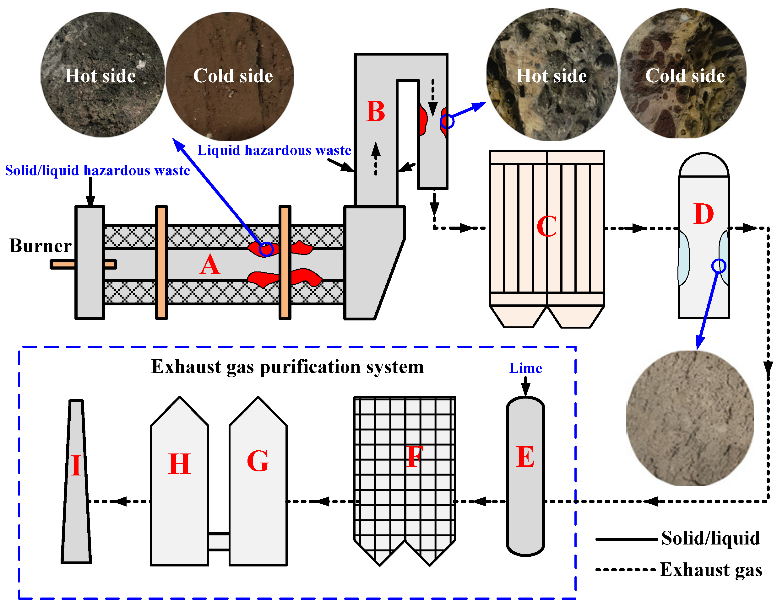
2.1. Experimental Materials

As illustrated in Figure 1, hazardous waste incineration takes place in the combustion chamber on a rotary kiln (Diameter = 3.0 m, Length = 11.4 m) combined with a secondary combustion chamber (Diameter = 3.6 m, Length = 13.5 m), which is located in Tengzhou, Shandong, China, and handles 100 tons of waste per day. The solid and semisolid hazardous wastes are directly sent to the rotary kiln through the feeder for incineration, and the liquid hazardous wastes are injected into the rotary kiln and secondary combustion chamber for incineration according to the difference in calorific value. hazardous wastes undergo high-temperature decomposition and combustion reactions in the rotary kiln, resulting in a great reduction in volume, and the burned residues flow continuously from the tail of the rotary kiln. According to the different operating temperatures, hazardous waste incineration through the rotary kiln is divided mainly into ashing mode (850–1000 °C) and slagging mode (1100–1400 °C) [19]. The case for the incinerator that we investigated in this study is ashing mode in consideration of the advantage for the lower overall operating costs, and the incineration temperature is controlled at approximately 850 °C. The exhaust gas emitted by the rotary kiln enters the secondary combustion chamber for further incineration. In the secondary combustion chamber, the temperature is guaranteed to be maintained at approximately 1100 °C, and the residence time of the exhaust gas is not less than 2 s so that the organic matter and dioxins are completely decomposed to achieve harmless disposal [28].
The treatment process of exhaust gas is described as follows: the high-temperature gas emitted by the secondary combustion chamber first enters the waste heat boiler to produce steam by recovering the energy from the gas, which causes the reduction of gas temperature to 500–600 °C; the exhaust gas is then decreased to approximately 200 °C after passing through the quench tower to prevent the resynthesis of toxic gases such as dioxins [29]; after being extremely cooled, the exhaust gas will go through the purification systems mainly consisting of deacidification and dust removal and can be emitted through the chimney only after reaching the strict exhaust gas emission standards. Among these standards, to save energy and environmental protection, the high-salt wastewater of sewage stations is generally applied in the process of extremely cooling high-temperature flue gas, which will become the hidden danger of slagging ring formation on the wall of the quench tower.
High-alkali and high-halogen hazardous wastes are usually the main cause of slagging ring formation in the incineration process. In the case analyzed and discussed in this study, the slagging phenomenon occurs mainly in the second half of the kiln, exit flue of the secondary combustion chamber, and wall of the quench tower, which will narrow the passage of materials and exhaust gas and affect the stable operation of the system. Samples as received from the position located in the wall of A, B, and D in Figure 1 are ground to powder and sieved to particle sizes between 60 and 105 mm, named slag-RK, slag-SCC, and slag-QT, respectively. The slagging samples were dried at 105 °C for 2 h and stored as the experimental samples. To reveal the formation and growth mechanisms of slagging rings, the “cold side” and “hot side” of slagging samples from rotary kilns and secondary combustion chambers, respectively, were analyzed in this study. The “cold side” is defined as the surface in contact with the refractory material, which is the initial layer to form the slagging ring, and the “hot side” is defined as the surface in contact with the high-temperature materials or flue gas, which can be considered the growth layer of the slagging ring.
Because the source of hazardous waste is not fixed, resulting in the wide variation of alkali content in the raw materials, in this study, the lining materials used in the incineration systems are Al2O3-Cr2O3 refractories, which have excellent properties to resist the erosion of alkali and alkaline earth due to high heat stability and corrosion resistance of Cr2O3 [24,30]. The experimental results also prove that the content of Cr is very low in the slagging samples discussed in this case, indicating that Cr2O3 does not participate in the chemical reactions that occur during the slagging ring formation.

2.2. Experimental Procedures

The microstructure and elemental compositions of slagging samples were observed through scanning electron microscopy-energy dispersive spectrometry (JSM-7800F, JEOL, Tokyo, Japan) with a typical accelerating voltage of 20 kV. X-ray fluorescence was used to determine the contents of the main elements in the slagging samples using an energy dispersive instrument (E3, The Netherlands). The slagging substances belong to the residues of HW incineration, and the amorphous compositions are almost nonexistent due to the decomposition of most organic structures at high temperatures. Therefore, X-ray diffraction is an adequate method to analyze the possible crystalline structures existing in slagging samples. A Rigaku D/MAC/max 2500 v/pc instrument (DX2700, China) with Cu Ka radiation (40 kV, 200 mA, and λ = 1.5418 Å) was selected to acquire the diffraction data with a step size of 0.02° for 2θ values from 5 to 80°. The detailed chemical forms can be confirmed through Jade 6.0 software.

3. Results

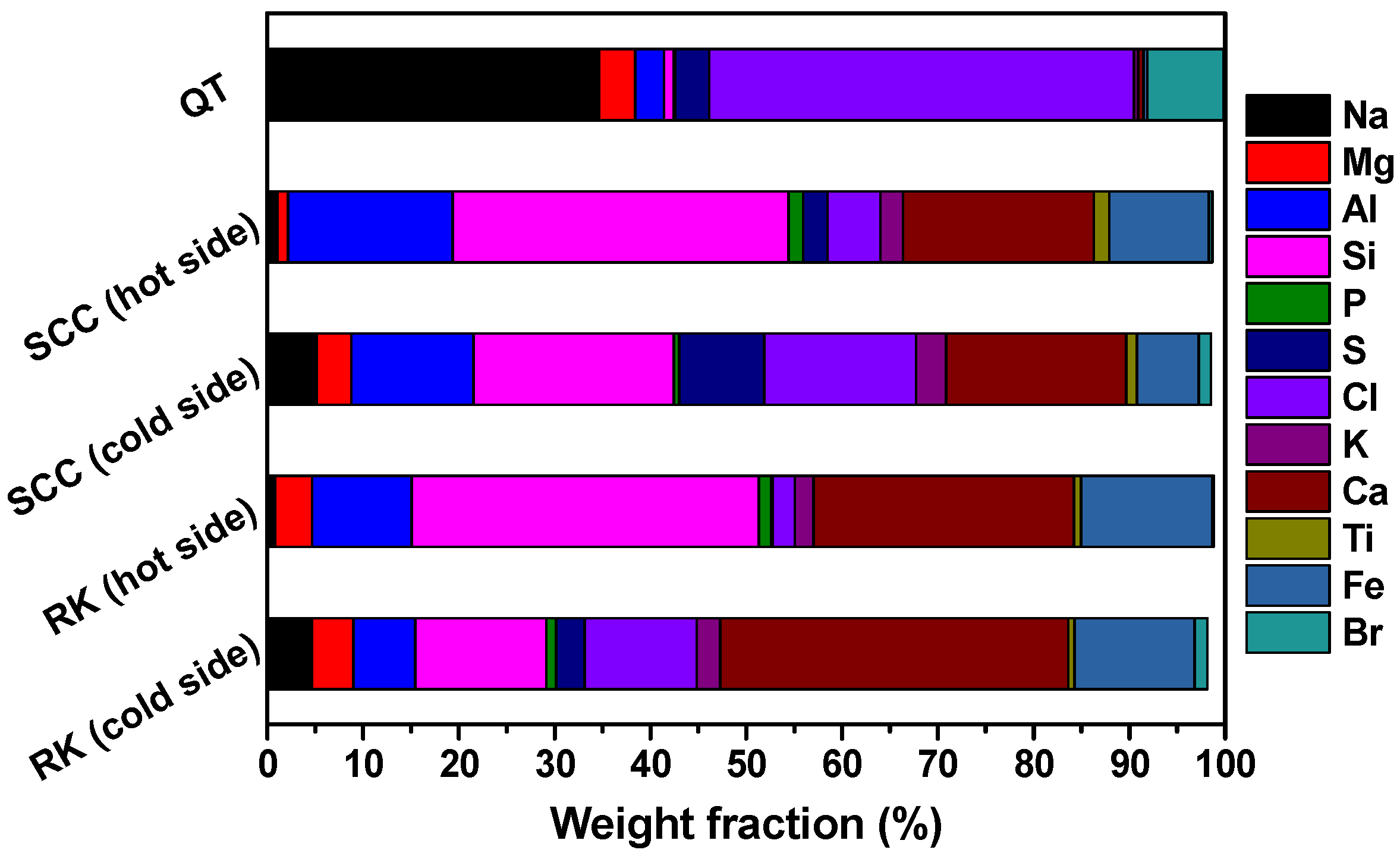
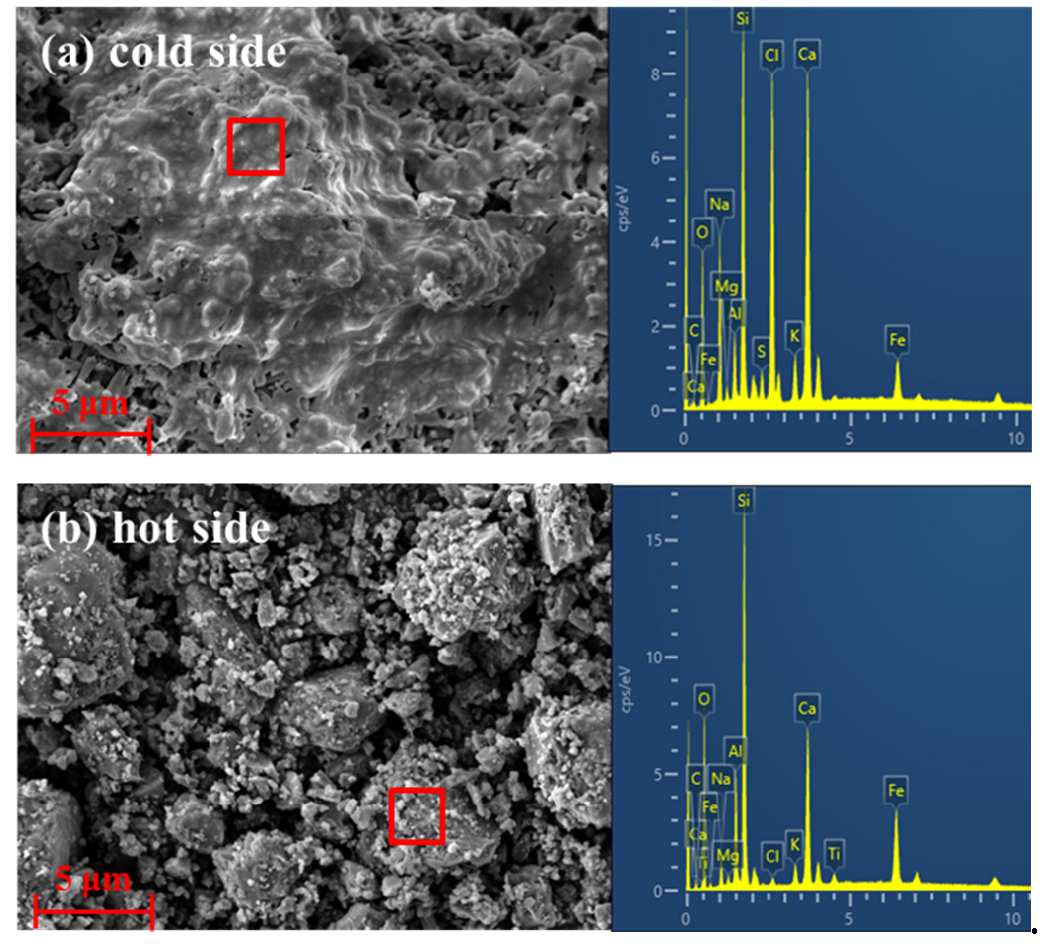
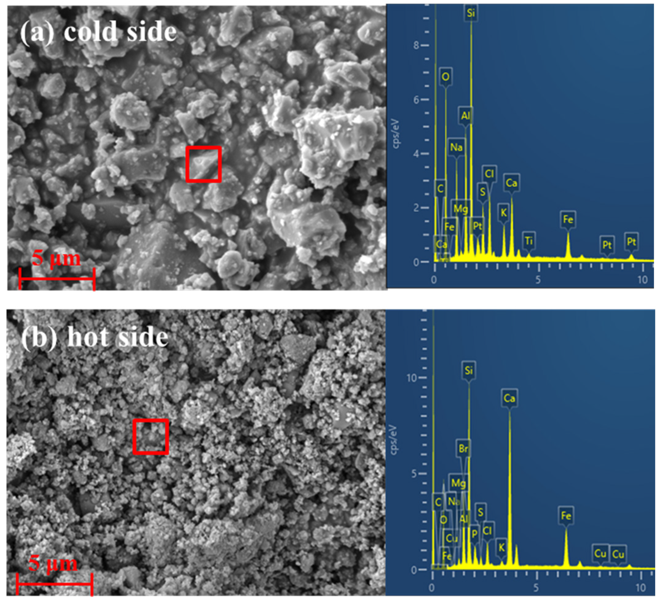
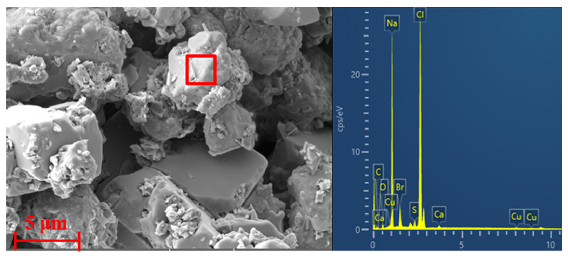
3.1. Morphology and Composition of Slagging Samples

Figure 2 illustrates the SEM micrographs and EDS analysis of the “cold side” and “hot side” of the slagging samples collected from the second half of the rotary kiln. As shown in Figure 2a, there is a significant molten phase on the contact surface between the slag and the refractory linings. As described by the results of EDS analysis, the “cold side” is characterized by high amounts of Na, Si, Cl, Ca, Fe, etc., elements. According to the previous study of our group [31], this part of the molten phase is mainly formed by alkali metal salts with low melting points, such as NaCl (801 °C) in terms of the current operating temperature of the rotary kiln. The SEM micrograph of the contact surface between the slag and the materials illustrated in Figure 2b presents the aggregation of particles of different sizes on the “hot side”, which are composed mainly of Al, Si, Ca, Fe, etc. elements. Zhu et al. [32] found that the main chemical compositions of hazardous waste incineration residue are SiO2, Al2O3, Fe2O3, CaO, and MgO, which is consistent with the analyzed results of “hot side”. This indicates that the aggregated characteristics of incineration residue with various sizes cause the growth of slagging rings in the second half of the rotary kiln.
When the fly ashes are brought into the secondary combustion chamber by effluent gas, the high-temperature atmosphere will promote the conversion of ash into molten or semi-molten [33]. After entering the outlet flue, part of fly ash particles will precipitate from the effluent gas and condense on the tube wall. As illustrated in Figure 3a, it is obvious that the molten materials together with small particles of fly ash released from hazardous waste incineration adhere to the contact surface between the slag and the tube wall of the outlet flue of the secondary combustion chamber. The results determined by EDS analysis indicate that the components of the “cold side” are composed mainly of Na, Al, Si, S, Cl, Ca, Fe, etc., elements. The presence of S in the slag indicates that the main mineral phases in the fly ash particles have further chemical reactions with SO2 gases in the exhaust gas at high temperatures [22,34]. Figure 3b shows that the “hot side” where the slag is in contact with the high-temperature exhaust gas is more of the condensation and accumulation of micron and submicron particles, and the main components are consistent with the “cold side”. However, the content of Na, Cl, etc. elements is significantly decreased, indicating that the low-melting-point alkali metal salts mainly play an important role in the initial formation of slag, while in the growth process of the slag, the role of molten salt is more like a “glue” for the secondary deposits.
Figure 4 illustrates that the microscopic morphology of the slag obtained from the wall of the quench tower is formed by regular massive crystalline substances, which are composed mainly of micron-sized NaCl crystal grains, as shown by the EDS results, indicating that the application of high-salt wastewater for spraying in the quench tower will cause the precipitation and crystallization process of salt particles on the wall with the rapid reduction of exhaust gas temperature. As the water continuously evaporates, the formed slag gradually hardens and firmly adheres to the wall.
As shown in Figure 5, the average compositions and contents of slagging samples measured by XRF are consistent with the results obtained from EDS. Whether it is the second half of the rotary kiln or the exit flue of the secondary combustion chamber, the molten softening layer formed at the beginning of slagging contains a large amount of Na, Cl, etc. elements. Taking the XRF results of the slagging sample collected from the rotary kiln as an example, the contents of Na and Cl on the “cold side” are approximately 5.67- and 5.15-fold, respectively, compared to the contents of Na and Cl of the “hot side”, indicating that the presence of low-melting alkali metal salts on the contact surface between the slag and refractories or walls is the key cause of slagging formation. Elements such as Si, Al, Ca, and Fe are the main components of the slag, resulting in the formation of dense and highly hard slag [35]. In the quench tower, the results determined by XRF also confirm that Na and Cl are the main components of the slagging sample again.

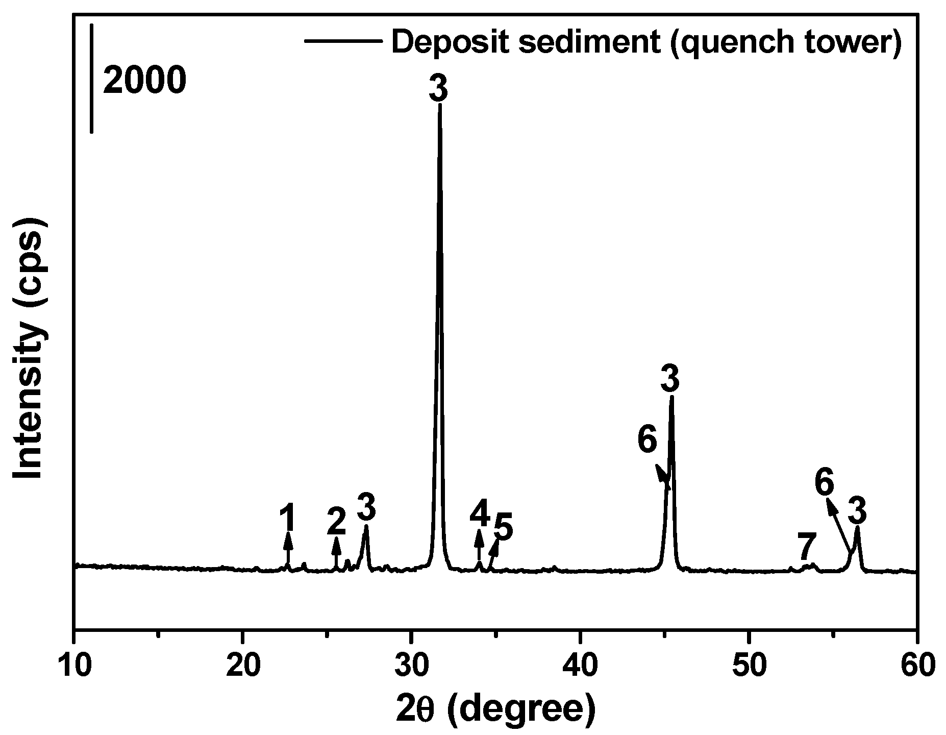
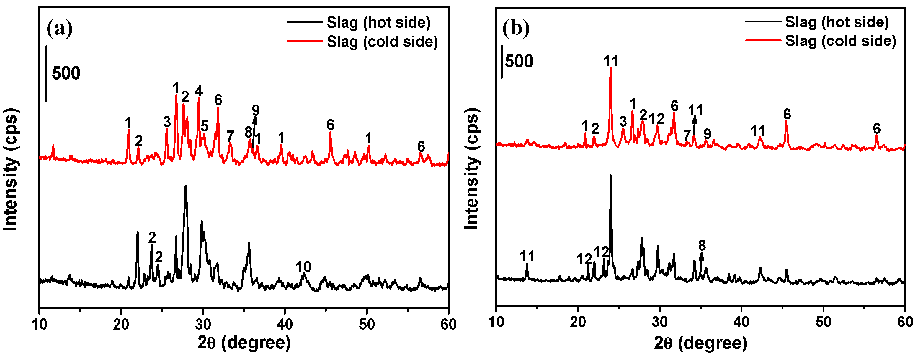
3.2. XRD Crystalline Phase Compositions in the Slagging Samples

The XRD analyses of the “cold side” and “hot side” of slagging samples collected from the second half of the kiln are illustrated in Figure 6a, in which the absorbance band areas of the mineral compositions are directly related to their percentages [36]. The various bands of each crystalline phase indicate that the crystal structure planes are diverse. As shown in the figure, the main crystalline phases of the sample surface (“cold side”) in contact with the refractory material linings consist of quartz (SiO2), labradorite (Ca0.65Na0.35(Al1.65Si2.35O8), halite (NaCl), iron oxides (Fe2O3, Fe3O4) and the compounds (diposide, ferrosilite, and magnesioderrite) formed through the reactions among CaO, MgO, Fe2O3, and SiO2. The color of the “cold side” is dark red due to the existence of hematite [37]. A large amount of alkali metal salts in the incineration slag of HWs can be considered the “chief culprit” of slagging ring formation. The sources of Na salts in the slag are composed of two main parts: (a) direct introduction of materials and (b) indirect formation by the reaction among components containing sodium and chlorine. The types of crystalline phases of the “hot side” of the slagging sample are consistent with those of the “cold side”, while the diffraction peak intensity of NaCl in the growing layer is significantly weakened. These results indicate that only a small amount of NaCl remains in the embryo body to fill the gaps, and most of the NaCl leached to the surface during the densification process of the embryo body and is carried away by exhaust gas or incineration residual slags.
The presence of NaCl in the slag will not only reduce the melting point of the slag and enhance its adhesion on the refractory surface but also the formed liquid phase will penetrate the refractory interior and firmly adhere to the surface of the refractory lining after cooling [38]. Simultaneously, the liquid phase formed by the low-melting alkali metal salt can also promote other high-melting-point oxides in the slag to react with each other to form silicate or aluminosilicate with a lower melting point. The main reactions are shown as (1)–(5). These low-melting-point compositions will continually adhere to the surface of the refractory lining, forming the slagging ring.
Na2O + Al2O3 + 6SiO2 = 2NaAlSi3O8
CaO + Al2O3 + 6SiO2 = Ca(AlSi3O8)2
CaO + MgO + 2SiO2 = CaMgSi2O6
MgO + FeO + 2SiO2 = MgFeSi2O6
MgO + Fe2O3 = MgFe2O4
As shown in Figure 6b, the primary deposit layer (“cold side”) occurring in the exit flue of the secondary combustion chamber also contains large amounts of low-melting-point NaCl, and the diffraction peak intensity of NaCl in the growth layer (“hot side”) is also significantly weakened, which is similar with that of slagging sample collected from the rotary kiln. The sources of Na salts consist mainly of gas and fly ash leaving the rotary kiln and incineration of waste salt solution injected into the secondary combustion chamber. According to the study of Reichelt et al. [39] on the mineralogical composition of deposits from the municipal solid waste (MSW) boiler, the primary deposit usually contains sulfates and higher contents of chlorides, which is also confirmed by our results. The main crystalline phases that form the slagging ring will undergo certain changes due to the higher incineration temperature (approximately 1100 °C) in the secondary combustion chamber, higher than in the rotary kiln, showing mainly that the crystalline phase substances containing S and Cl occupy the dominant position, mainly because the SO2 and HCl gases generated during hazardous waste incineration further react with the aluminosilicate in the fly ash entering the secondary combustion chamber at high temperature [22], resulting in the formation of lazurite (Na8.56(Al6Si6O24)(SO4)1.56S0.44), sodalite (Na8(AlSiO4)6(ClO4)2) and hauyne (Na6Ca2Al6Si6O24(SO4)2) compounds containing sulfate rand chlorate radicals.
To further compare the compositions of slagging samples in different parts of the equipment, the reference intensity ratio (RIR) method [36] is used to carry out the quantitative analysis for XRD results. The formula is given by:
I j I s = R I R s j W j W s
where W denotes the weight fraction, I denotes the intensity, and the subscripts j and s indicate phase j and standard phases, respectively. For the corundum (Al2O3) standard phase, the reference intensity ratio (RIR) was determined according to the most intense corundum peak, Icor, and the most intense peak from phase j, Ij, in a 1:1 mixture by weight. If quartz (SiO2) is selected as the standard, the formula used to calculate the concentrations of any phase j can be converted as follows:
W j = W q u a R I R c o r q u a R I R c o r j I j I q u a
Considering the differences in diffraction peak widths for the crystalline phases in the adsorbents, the intensity ratios can be more accurately calculated by integral intensity (i.e., peak area) of single greatest peak than linear intensity (i.e., peak height). If the content of trace elements in the slagging samples is ignored, the mass fraction of main crystalline phases in the slagging samples gained from the middle and rear sections of rotary kilns can be calculated through the RIR method. The quantitative results of main crystalline phases in the samples collected from the middle and rear sections of rotary kilns and the exit flue of the second combustion chamber are listed in Table 1 and Table 2, respectively. It can be found that the mass fraction of main crystalline phases in the interface between slag and refractory lining (“Cold side”) has a significant difference compared with the “Hot side”, mainly reflecting in a higher concentration of alkali metal salts.
The XRD analysis results of slagging samples in the quench tower are shown in Figure 7. The main crystal phases of the deposited sediment are found as NaCl, NaBr, and sulfate. Among these, the mass fraction of NaCl, NaBr, and Na2SO4 can be calculated as 73.08%, 10.25%, and 11.11%, respectively according to the XRF results illustrated in Figure 5, accounting for more than 94%, which are the main compounds. Na salts arise from two sources: (a) release by hazardous waste incineration and (b) precipitation out of the high-salt wastewater generated by the exhaust gas deacidification process. In recent years, an increasing number of hazardous waste incineration plants have preferred to use high-salt wastewater to replace industrial water for spraying. On the one hand, this method can save water resources and reduce the cost of exhaust gas treatment; on the other hand, this method can solve the treatment problem of high-salt wastewater. However, salt particles will constantly precipitate from the high-temperature exhaust gas and solidify on the inner surface of the quench tower during rapid cooling. In addition, because the salt particles are mixed with a certain amount of fly ash particles during the solidification process, the slagging sample appears gray instead of white.

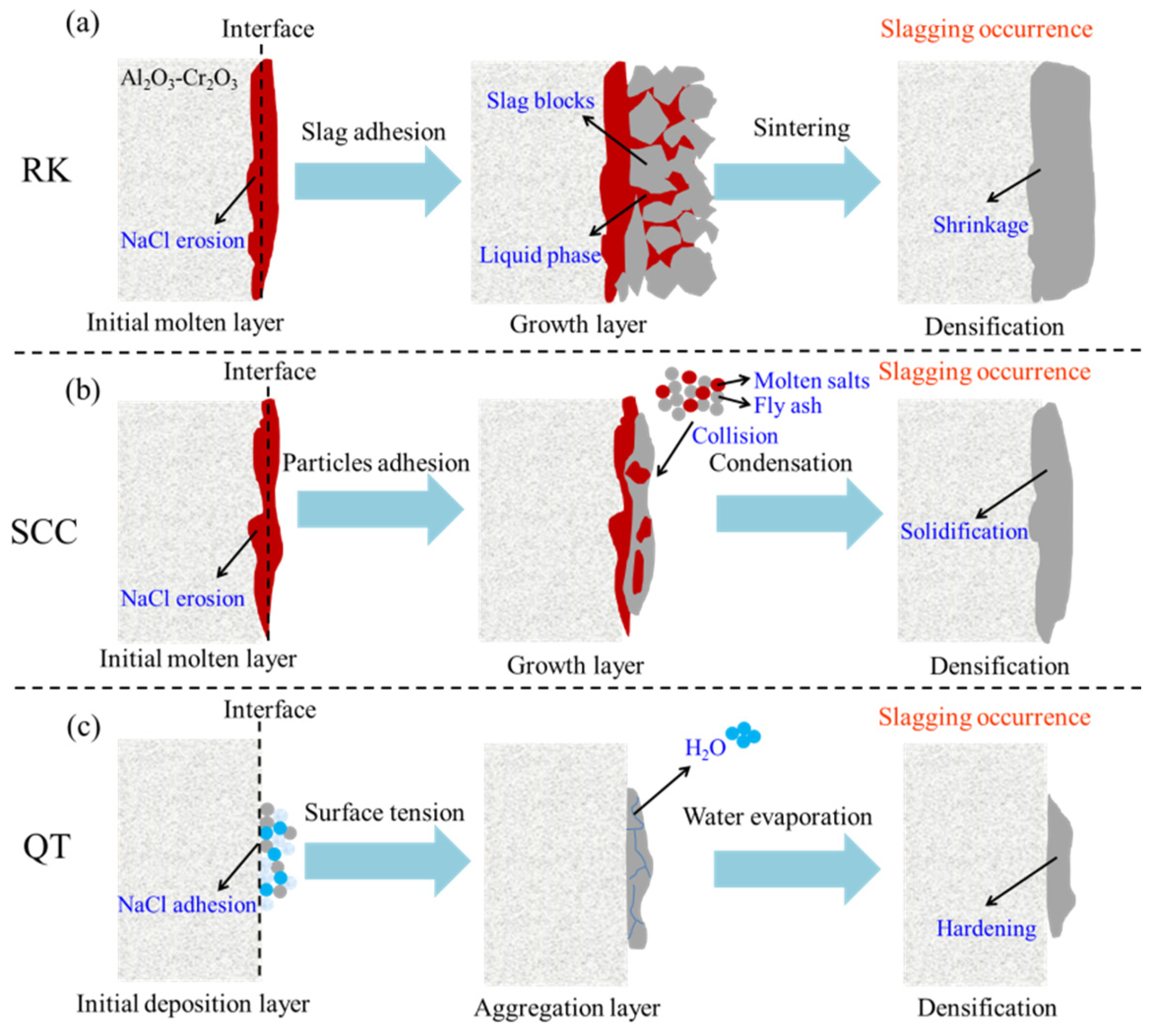
3.3. Slagging Ring Formation and Growth Mechanisms

Most system slagging is caused by ash or slag in the molten/softened state, which directly hardens due to sudden cooling when it encounters the heating surface [40]. In the second half of the rotary kiln, the adhesion of incineration residual slag on the surface of the refractory materials caused by low-melting alkali metal salts forms the initial layer of the slagging ring. The dissolution and transformation of the Al2O3 component from the refractory lining cause the erosion of slag, and the Fe2O3 component of the slag also takes part in the concurrent reaction, which is confirmed by the XRD results illustrated in Figure 6. On the interface, there is a higher concentration of Fe2O3 according to the quantitative results shown in Table 1. And the viscosity of slag and the basicity bandgap (between lining and slag) are usually the major factors, which control the corrosion behavior of Al2O3-Cr2O3 refractories. However, as the accumulation of Fe2O3 component starting in the interface forms the (Fe, Cr)2O3 solid solution through the reactions (6)–(8), the formation of this layer acts as a barrier to the flow of molten slag into the refractory structure and consequently the corrosion rate ceases with time [30]. Therefore, the depth of slag corrosion is usually mm order of magnitude, and visible corrosion is not easily been observed. This indicates that Al2O3-Cr2O3 refractories have excellent properties to resist the erosion of alkali. The high corrosion resistance of Al2O3-Cr2O3 refractories is due to the extremely low solubility of Cr2O3 in the molten slag. This also explains why the Cr element is hardly found in the measured results of slagging samples.
Al2O3 + Cr2O3 = (Al, Cr)2O3
(Al, Cr)2O3 + Fe2O3 = (Fe, Al, Cr)2O3 + Al2O3
(Fe, Al, Cr)2O3 = (Fe, Cr)2O3 + Al2O3
The “ashing mode” adopted by the rotary kiln in this study has an incineration temperature lower than the melting point of most oxides and their derivatives. Therefore, the growth of the slagging ring is more likely to be the “liquid phase sintering” process of HW incineration residues. Yan et al. [41] found that hazardous waste incineration ash had significant agglomeration after sintering, producing bigger-size and denser ash particles. As shown in Figure 8a, the liquid phase formed by alkali metal salts with a low melting point in the rotary kiln promotes mutual bonding between the slag particles and the initial formation layer of the slagging ring through flow mass transfer and accelerates the volume shrinkage through the capillary force until the dense embryo body is formed through sintering. This process can be constantly repeated until the anomalous growth of the slagging ring affects normal production, and the rotary kiln has to be shut down for slag removal.
The initial layer formation mechanism of the slagging ring at the exit flue of the secondary combustion chamber is similar to the formation mechanism at the second half of the rotary kiln, which is that the low-melting-point materials are deposited on the surface of the flue and then adhere firmly to the lining surface after cooling through liquid phase erosion. As illustrated in Figure 8b, a significant melting layer can be found on the surface in contact with the flue. However, the growth process of the slagging ring at the exit flue of the secondary combustion chamber is not realized by the sintering process, and it is more likely being achieved by repeated “accumulation”. This process is similar to the deposition of fly ash particles on the surface of heat exchangers [39,40]. The temperature in the secondary combustion chamber is usually higher than or close to the melting temperature of the most crystalline phase substances in the fly ash particles, especially at the location of the incineration nozzle. Therefore, most of the fly ash particles in the exhaust gas are in a molten and semi-molten state and have strong cohesiveness. After being in contact with the initial forming surface of the slagging ring, the molten and semi-molten ash particles continuously deposit and solidify on the surface under the action of surface tension, gradually forming a dense embryo body.
The formation mechanisms of the slagging ring on the wall of the quench tower belong to the hardening process of salt particles. As shown in Figure 8c, the salt solution with a certain viscosity first adheres to the inner surface of the wall, and as the water evaporates, a firm bond is formed between the salt particles, forming the initial layer. The growth mechanism of the slagging ring is consistent with the formation mechanism. However, as the salt layer accumulates, the pressure withstood by the salt particles increases, which will cause the crystal lattice near the salt grain joints to tilt, and the intercrystalline contact area will increase, making the consolidation between the salt particles stronger on the wall of the quench tower. As a result, a hard and dense slagging ring is formed.

4. Conclusions and Recommendations

The slagging occurrence in the hazardous waste incineration system will lead to passage blockage, cause negative pressure fluctuation, and reduce treatment capacity. In serious cases, the system will be shut down, and the equipment may be damaged. The slagging samples collected under actual industrial operating conditions were measured and analyzed to reveal the formation and growth mechanisms of slagging rings at different positions during hazardous waste incineration. Slagging ring formation is caused by many reasons. To fundamentally solve the slagging problem, it is meaningful to start with a material formula, operation adjustment, and design optimization.
(1) Second half of the rotary kiln
The formation causes of slagging rings in the second half of the rotary kiln start with the penetration of low-melting salts (NaCl) into the surface cracks of refractory materials and grow with the liquid sintering of incineration residuals such as labradorite, iron oxides, diposide, ferrosilite, magnesioderrite, etc. Therefore, the content of alkali metal salts in the materials should be reasonably controlled, which can effectively prevent the formation of a large amount of liquid phase in the rotary kiln to promote slagging ring formation. At the same time, the cracks on the refractory surface are also the key factor in the formation of slagging rings. Sintered refractory bricks have better compactness than refractory castables and can be used in positions where the slagging phenomenon is likely to occur. In the operation process of a rotary kiln, a rapid change in thermal stress should also be avoided, which may cause the widening of cracks. In addition, strengthening the sealing of the second half of the rotary kiln and reducing the entry of cold air is also an effective means to prevent the formation of slagging rings. After the slagging ring appears in the rotary kiln, a movable “torch” can be used to melt the adhered slag at high temperatures so that the molten slag can successfully enter the slag discharge system.
(2) Exit flue of the secondary combustion chamber
The cause of the slagging ring in the flue at the exit of the secondary combustion chamber is also that the low-melting salts form a firmly adhesive layer on the surface of the flue and then grow up with the continuous deposition and solidification of molten/semi-molten ash particles in the exhaust gas. The slagging occurrence is mainly due to the change in the shape and structure of the outlet flue, causing the variation in the gas flow field, which leads to the continuous impact of ash particles in the exhaust gas on the wall surface. After a long operation time, a slagging phenomenon will occur at the outlet flue. Therefore, the design of the outlet flue of the secondary combustion chamber should ensure the smooth flow line of the exhaust gas and avoid the formation of a local eddy current region.
(3) Wall of the quench tower
The rapid crystallization and coalescence of inorganic salts separated from high-salt wastewater are the main reasons for slagging on the inner wall of the quench tower. Given the various advantages of high-salt wastewater for spraying, it is not a practical solution method to disuse it. Recently, a chemical drug, mainly consisting of sodium citrate, disodium DTA, sodium dodecylbenzene sulfonate, and hydrolyzed polymaleic anhydride, was shown to prevent salt accumulation from blocking, keep the salt loose, and increase the fluidity of salt through the threshold effect and lattice distortion. However, the price of the drug must be controlled within a suitable range by developing a new production process before it can potentially be used to solve the slagging problem caused by the spray of high-salt wastewater in the quench tower.

Author Contributions

Conceptualization, J.Z., B.L. and X.W.; methodology, J.Z., Z.Z. and B.L.; software, J.Z.; formal analysis, Z.Z.; investigation, J.Z. and Z.Z.; resources, X.W.; writing—original draft preparation, J.Z. and Z.Z.; writing—review and editing, X.W. All authors have read and agreed to the published version of the manuscript.

Funding

This research was funded by the National Natural Science Foundation of China, grant number 51736010.

Acknowledgments

The authors thank the plant for supplying some necessary materials and data.

Conflicts of Interest

The authors declare no conflict of interest.

References

  1. Lei, X.; Deng, Y.F.; Mancl, K. Environmental disaster reduction-oriented centralized treatment of hazardous wastes: A novel approach for production-distribution decision optimization in China. Int. J. Disast. Risk Re. 2019, 40, 101263. [Google Scholar]
  2. Wang, B.; Wu, C.; Reniers, G.; Huang, L.; Kang, L.G.; Zhang, L.B. The future of hazardous chemical safety in China: Opportunities, problems, challenges and tasks. Sci. Total Environ. 2018, 643, 1–11. [Google Scholar] [CrossRef] [PubMed]
  3. Liu, G.Y.; Yang, Z.F.; Chen, B.; Zhang, Y.; Su, M.R.; Zhang, L.X. Emergy evaluation of the urban solid waste handing in Liaoning province, China. Energies 2013, 6, 5486–5506. [Google Scholar] [CrossRef] [Green Version]
  4. Guo, W.; Xi, B.D.; Huang, C.H.; Li, J.X.; Tang, Z.R.; Li, W.; Ma, C.Y.; Wu, W.X. Solid waste management in China: Policy and driving factors in 2004–2019. Resour. Conserv. Recy. 2021, 173, 105727. [Google Scholar] [CrossRef]
  5. Zeng, J.C.; Yue, Y.; Gao, Q.; Zhang, J.; Zhou, J.Z.; Pan, Y.; Qian, G.R.; Tang, J.; Ruan, J.B. Co-treatment of hazardous wastes by the thermal plasma to produce an effective catalyst. J. Clean. Prod. 2019, 208, 243–251. [Google Scholar] [CrossRef]
  6. Dong, J.; Tang, Y.J.; Nzihou, A.; Chi, Y.; Weiss-Hortala, E.; Ni, M.J. Life cycle assessment of pyrolysis, gasification and incineration waste-to-energy technologies: Theoretical analysis and case study of commercial plants. Sci. Total Environ. 2018, 626, 744–753. [Google Scholar] [CrossRef]
  7. Liu, Z.Q.; Liu, Z.H.; Li, X.L. Status and prospect of the application of municipal solid waste incineration in China. Appl. Therm. Eng. 2006, 26, 1193–1197. [Google Scholar] [CrossRef]
  8. Lai, Z.Y.; Ma, X.Q.; Tang, Y.T.; Lin, H. A study on municipal solid waste (MSW) combustion in N2/O2 and CO2/O2 atmosphere from the perspective of TGA. Energy 2011, 36, 819–824. [Google Scholar] [CrossRef]
  9. Helsen, L.; Bosmans, A. Waste-to-Energy through thermochemical processes: Matching waste with process. In Proceedings of the International Academic Symposium on Enhanced Landfill Mining, Houthalen-Helchteren, Belgium, 4–6 October 2010; pp. 133–180. [Google Scholar]
  10. Xia, Z.H.; Long, J.S.; Yan, S.; Bai, L.; Du, H.L.; Chen, C.X. Two-fluid simulation of moving grate waste incinerator: Comparison of 2D and 3D bed models. Energy 2021, 216, 119257. [Google Scholar] [CrossRef]
  11. Van Caneghem, J.; Brems, A.; Lievens, P.; Block, C.; Billen, P.; Vermeulen, I.; Dewil, R.; Baeyens, J.; Vandecasteele, C. Fluidized bed waste incinerators: Design, operational and environmental issues. Prog. Energ. Combust. 2012, 38, 551–582. [Google Scholar] [CrossRef]
  12. Block, C.; Van Caneghem, J.; Van Brecht, A.; Wauters, G.; Vandecasteele, C. Incineration of hazardous waste: A sustainable process? Waste Biomass Valori. 2015, 6, 137–154. [Google Scholar] [CrossRef]
  13. Rozumová, L.; Motyka, O.; Cabanová, K.; Seidlerová, J. Stabilization of waste bottom ash generated from hazardous waste incinerators. J. Environ. Chem. Eng. 2015, 3, 1–9. [Google Scholar] [CrossRef]
  14. Hong, J.L.; Han, X.F.; Chen, Y.L.; Wang, M.; Ye, L.P.; Qi, C.C.; Li, X.Z. Life cycle environmental assessment of industrial hazardous waste incineration and landfilling in China. Int. J. Life Cycle Assess. 2017, 22, 1054–1064. [Google Scholar] [CrossRef]
  15. Jiang, X.G.; Li, Y.H.; Yan, J.H. Hazardous waste incineration in a rotary kiln: A review. Waste Disposal Sustain. Energ. 2019, 1, 3–37. [Google Scholar] [CrossRef] [Green Version]
  16. Li, M.; Wang, C.; Cen, K.F.; Ni, M.J.; Li, X.D. PCDD/F emissions during startup and shutdown of a hazardous waste incinerator. Chemosphere 2017, 181, 645–654. [Google Scholar] [CrossRef] [PubMed]
  17. Yu, J.; Qiao, Y.; Jin, L.M.; Ma, C.; Paterson, N.; Sun, L.S. Removal of toxic and alkali/alkaline earth metals during co-thermal treatment of two types of MSWI fly ashes in China. Waste Manage. 2015, 46, 287–297. [Google Scholar] [CrossRef]
  18. Li, N.; Vainio, E.; Hupa, L.; Hupa, M.; Zabetta, E.C. High-temperature corrosion of refractory materials in biomass and waste combustion-Method development and tests with alumina refractory exposed to a K2CO3-KCl mixture. Energ. Fuel 2017, 31, 10046–10054. [Google Scholar] [CrossRef]
  19. Weinberg, A.V.; Varona, C.; Chaucherie, X.; Goeuriot, D.; Poirier, J. Extending refractory lifetime in rotary kilns for hazardous waste incineration. Ceram. Int. 2016, 42, 17626–17634. [Google Scholar] [CrossRef]
  20. Qian, J.J.; Jiang, X.G.; Wang, F.; Chi, Y.; Yan, J.H. Effect of fluorine and chlorine on slag melting characteristics: Experimental study and simulation by neural networks. Thermochim. Acta 2011, 526, 29–34. [Google Scholar] [CrossRef]
  21. Bolis, V.; Capón-García, E.; Weder, O.; Hungerbühler, K. New classicication of chemical hazardous liquid waste for the estimation of its energy recovery poyential based on existing measurements. J. Clean. Prod. 2018, 183, 228–1240. [Google Scholar] [CrossRef]
  22. Weinberg, A.V.; Varona, C.; Chaucherie, X.; Goeuriot, D.; Poirier, J. Corrosion of Al2O3-SiO2 refractories by sodium and sulfur vapors: A case study on hazardous waste incinerators. Ceram. Int. 2017, 43, 5743–5750. [Google Scholar] [CrossRef]
  23. Cheng, G.S.; Zhao, Y.; Long, F.; Zhang, J.H.; Zhao, T.F.; Liu, L.; Wang, X.Q.; Dong, C.Q. Analysis and prediction of corrosion of refractory materials by sodium salts during waste liquid incineration-Thermodynamic study. Materials 2020, 13, 4729. [Google Scholar] [CrossRef] [PubMed]
  24. Chen, D.; Huang, A.; Gu, H.Z.; Zhang, M.J.; Shao, Z.J. Corrosion of Al2O3-Cr2O3 refractory lining for high-temperature solid waste incinerator. Ceram. Int. 2015, 41, 14748–14753. [Google Scholar] [CrossRef]
  25. Weinberg, A.V.; Goeuriot, D.; Poirier, J.; Varona, C.; Chaucherie, X. Mullite-zirconia composite for the bonding phase of refractory bricks in hazardous waste incineration rotary kiln. J. Eur. Ceram. Soc. 2021, 41, 995–1002. [Google Scholar] [CrossRef]
  26. Bouchetou, M.L.; Poirier, J.; Arbelaez Morales, L.; Chotard, T.; Joubert, O.; Weissenbacher, M. Synthesis of an innovative zirconia-mullite raw materials sintered from andalusite and zircon precursors and an evaluation of its corrosion and thermal shock performance. Ceram. Int. 2019, 45, 12832–12844. [Google Scholar] [CrossRef]
  27. Ren, B.; Li, Y.W.; Nath, M.; Wang, Q.H.; Xu, Y.B. Enhanced alkali vapor attack resistance of bauxite-SiC refractories for the working lining of cement rotary kilns via incorporation of andalusite. Ceram. Int. 2018, 44, 22113–22120. [Google Scholar] [CrossRef]
  28. Wahid, S.S. Operation and performance testing of the hazardous (biomedical) waste incineration plant for hospitals. Int. J. Appl. Eng. Res. Dev. 2013, 3, 11–24. [Google Scholar]
  29. Ma, P.; Ma, Z.Y.; Yan, J.H.; Chi, Y.; Ni, M.J.; Cen, K.F. Industrial hazardous waste treatment featuring a rotary kiln and grate furnace incinerator: A case study in China. Waste Manag. Res. 2011, 29, 1108–1112. [Google Scholar] [CrossRef]
  30. Nath, M.; Ghosh, A.; Tripathi, H.S. Hot corrosion behavior of Al2O3-Cr2O3 refractory by molten glass at 1200 °C under static condition. Corros. Sci. 2016, 102, 153–160. [Google Scholar] [CrossRef]
  31. Zhao, J.; Wei, X.L.; Li, T.; Li, H.X.; Bin, F. Behavior of alkali metals in fly ash during waste heat recovery for municipal solid waste incineration. Energ. Fuel. 2018, 32, 4417–4423. [Google Scholar] [CrossRef]
  32. Zhu, H.M.; Wang, Y.F.; Jing, N.J.; Jiang, X.G.; Lv, G.J.; Yan, J.H. Study on the evolution and transformation of chlorine during co-processing of hazardous waste incineration residue in a cement kiln. Waste Manag. Res. 2019, 37, 495–501. [Google Scholar] [CrossRef]
  33. Krishnamoorthy, V.; Pisupati, S.V. A critical review of mineral matter related issues during gasification of coal in fixed, fluidized, and entrained flow gasifiers. Energies 2015, 8, 10430–10463. [Google Scholar]
  34. Capablo, J.; Ballester, J. Experimental study of the kinetics of sulfation of alkali chloride deposits. Fuel Process. Technol. 2015, 140, 215–221. [Google Scholar]
  35. Phongphiphat, A.; Ryu, C.; Finney, K.N.; Sharifi, V.N.; Swithenbank, J. Ash deposit characterisation in a large-scale municipal waste-to-energy incineration plant. J. Hazard. Mater. 2011, 186, 218–226. [Google Scholar] [CrossRef] [PubMed]
  36. Hillier, S. Accurate quantitative analysis of clay and other minerals in sandstones by XRD: Comparison of a Rietveld and a reference intensity ratio (RIR) method and the importance of sample preparation. Clay Miner. 2000, 35, 291–302. [Google Scholar]
  37. Stjernberg, J.; Lindblom, B.; Wikström, J.; Antti, K.L.; Odén, M. Microstructural characterization of alkali metal mediated high temperature reactions in mullite based refractories. Ceram. Int. 2010, 36, 733–740. [Google Scholar] [CrossRef] [Green Version]
  38. Wang, Y.B.; Tan, H.Z.; Wang, X.B.; Cao, R.J.; Wei, B. The condensation and thermodynamic characteristics of alkali compound vapors on wall during wheat straw combustion. Fuel 2017, 187, 33–42. [Google Scholar] [CrossRef]
  39. Reichelt, J.; Pfrang-Stotz, G.; Bergfeldt, B.; Seifert, H.; Knapp, P. Formation of deposits on the surfaces of superheaters and economisers of MSW incinerator plants. Waste Manage. 2013, 33, 43–51. [Google Scholar]
  40. Brossard, J.M.; Diop, I.; Chaucherie, X.; Nicol, F.; Rapin, C.; Vilasi, M. Superheater fireside corrosion mechanisms in MSWI plants: Lab-scale study and on-site results. Mater. Corros. 2011, 62, 543–548. [Google Scholar]
  41. Yan, M.; Zhou, Z.H.; Zheng, R.D.; Jiang, J.H.; Feng, H.Y.; Yu, C.M.; Zhu, G.J.; Hantoko, D. Low-temperature sintering behavior of fly ash from hazardous waste incinerator. Effect of temperature and oxygen on ash properties. J. Environ. Chem. Eng. 2021, 9, 105261. [Google Scholar]
Figure 1. Schematic of the hazardous waste incineration process located in Tengzhou, Shandong, China: (A) Rotary kiln, (B) Second combustion chamber, (C) Waste heat boiler, (D) Quench tower, (E) Dry deacidification tower, (F) Bag-type dust collector, (G) Pickling tower, (H) Alkaline washing tower, (I) Chimney.
Energies 14 07561 g001
Figure 2. SEM micrographs and EDS analysis of the slagging samples collected from the second half of the rotary kiln: (a) surface in contact with the refractory material; and (b) surface in contact with the high-temperature materials.
Energies 14 07561 g002
Figure 3. SEM micrographs and EDS analysis of the slagging samples collected from the exit flue of the secondary combustion chamber: (a) surface in contact with the tube wall; and (b) surface in contact with the high-temperature exhaust gas.
Energies 14 07561 g003
Figure 4. SEM micrographs and EDS analysis of the slagging samples collected from the wall of the quench tower.
Energies 14 07561 g004
Figure 5. Determination of the main elemental compositions and contents in slagging samples by the XRF method.
Energies 14 07561 g005
Figure 6. XRD patterns of slagging samples during hazardous waste incineration: (a) middle and rear sections of rotary kilns; (b) exit flue of second combustion chamber. The main crystalline phases are: (1) quartz (SiO2), (2) labradorite (Ca0.65Na0.35(Al1.65Si2.35O8)), (3) anhydrite (CaSO4), (4) calcium carbonate (CaCO3), (5) diposide (CaMgSi2O6), (6) halite (NaCl), (7) hematite (Fe2O3), (8) magnesioferronite (MgFe2O4), (9) magnetite (Fe3O4), (10) magnesium iron oxide (MgO-FeO), (11) hauyne (Na6Ca2Al6Si6O24(SO4)2), (12) nepheline (KNa3(AlSiO4)4).
Energies 14 07561 g006
Figure 7. XRD patterns of deposit sediment in the wall of the quench tower, and the main crystalline phases can be shown as: (1) magnesium sulfate (MgSO4), (2) aluminum sulfate (Al2(SO4)3), (3) halite (NaCl), (4) sodium sulfate (Na2SO4), (5) sodium sulfite (Na2SO3), (6) sodium bromide chloride (NaBr0.1Cl0.9), (7) sodium bromide (NaBr).
Energies 14 07561 g007
Figure 8. Formation mechanisms of slagging rings during hazardous waste incineration: (a) second half of the rotary kiln (RK); (b) exit flue of the secondary combustion chamber (SCC); and (c) wall of the quench tower (QT).
Energies 14 07561 g008
Table 1. Quantitative results of main minerals in the slagging samples collected from the middle and rear sections of rotary kilns.
MineralsRIRcorIntensity Ratio (Ij/Iqua)Mass Fraction (%)
Cold SideHot SideCold SideHot Side
SiO23.341.001.006.672.20
Ca0.65Na0.35(Al1.65Si2.35O8)0.570.974.8737.8162.88
CaSO41.730.780.6810.032.87
CaCO33.121.344.919.5411.59
CaMgSi2O60.940.640.8315.086.51
NaCl4.711.820.748.631.16
Fe2O33.090.860.756.201.78
MgFe2O44.050.321.311.742.38
Fe3O45.030.562.952.484.32
MgO-FeO3.820.312.231.824.31
Table 2. Quantitative results of main minerals in the slagging samples collected from the exit flue of the second combustion chamber.
MineralsRIRcorIntensity Ratio (Ij/Iqua)Mass Fraction (%)
Cold SideHot SideCold SideHot Side
SiO23.341.001.006.223.42
Na6Ca2Al6Si6O24(SO4)23.002.014.3113.9216.37
KNa3(AlSiO4)41.091.321.7925.2018.78
Ca0.65Na0.35(Al1.65Si2.35O8)0.570.782.5728.3751.49
CaSO41.730.870.7110.451.26
NaCl4.712.261.089.952.61
Fe2O33.090.450.463.041.69
MgFe2O44.050.230.601.181.70
Fe3O45.030.401.181.672.68
Publisher’s Note: MDPI stays neutral with regard to jurisdictional claims in published maps and institutional affiliations.

