Abstract
To ensure the reliability of power supply, a dual power supply structure appears in the power distribution system. Power supply switching is a complex physical process. This paper presents a novel model of electromechanical contactors. This model can simulate the multi-physics process of power switching. This article completes the simulation framework for power switching through contactors for the first time. Among them, the structural topology for contactors is also proposed. On the basis of the novel structure topology, an equivalent magnetic circuit model is established to calculate the relationship between driving force, flux linkage, current, and displacement. Then, a co-simulation model is established between the above equations and Adams to obtain the speed characteristics and flight time of the contactor. Subsequently, through the use of Fluent and its secondary development, a magnetohydrodynamic model is established, and the above-mentioned velocity characteristics are imported into it to analyze the arcing characteristics of the contacts under the conditions of the transverse magnetic field and the insulating grid. The effectiveness of power switching is judged by comparing the flight time of the electromechanical model and the arcing time of the magnetohydrodynamic model. The prototype is manufactured and tested on the basis of simulation. Through experimental waveforms and high-speed photography, the accuracy of the simulation model and the practicability of the contactor are verified.
1. Introduction
With the continuous development of power distribution, a highly reliable multi-power hybrid power supply structure is used for sensitive loads [1,2]. As the core device, the contactor has a greater impact on the quality of power supply. The contactor plays a more important role in the switching process. However, in the work process, there are contact bounce and arc ablation. Such problems limit the improvement of the overall performance of the contactor. To reduce such problems, researchers have devoted themselves to the modeling and simulation of contactors.
Different topological structures, modeling techniques, and optimization methods have been proposed [3,4]. Several contactors have been designed by using analysis tools based on analytical solution [5,6]. In addition, researchers also use the finite element method to analyze and design the actuator [7]. Simulation methods based on artificial neural networks are gradually applied to the simulation modeling of actuators [8,9]. Modeling technology also plays an important role in the dynamic control of electromagnetic equipment. In [10], a flux-weakening control strategy is proposed to reduce the adverse effects of contact bounce. In [11,12], advanced displacement sensor technology is applied to the contactor, which can improve the dynamic performance of the contactor. In [13], a control strategy that uses reverse current to improve response speed is proposed. In [14], the tracking control of the vacuum circuit breaker is completed. In [15], the dynamic control of the contactor is completed based on the fuzzy control theory. In [16], the design, optimization, and control of the contactor are completed through modeling technology. The modeling technology of electromagnetic equipment has achieved great results [17,18]. The structural topology of electromagnetic actuators also tends to be diversified. The air gap of the contactor based on the electro-magnetic force driving actuator (EMFA) remains unchanged during the closing process, and the closing collision energy is small, which is beneficial to restrain the contact bounce. However, research on the analytical calculation model of the contactor with a constant air gap has not been published yet. Compared with the finite element model, the analytical model has a faster calculation speed. In addition, the simulation calculation process can be set through programming, which makes it easier to realize software interaction. On this basis, the serial calculation of multiple models is realized.
At present, the simulation work on plasma is mainly concentrated in the circuit breaker. In [19], the arc shape of the circuit breaker is studied, and the influencing factors behind the breakdown are revealed. In [20], the parallel contact system of the circuit breaker is studied. In [21], a circuit breaker arc model considering turbulence is established, which improves the accuracy of the simulation. In [22], a hybrid transient simulation of a vacuum arc using a field–circuit coupling method is proposed for a vacuum circuit breaker. The modeling research of arcs is mostly concentrated in the circuit breaker. However, there are few studies on the magnetohydrodynamic model of contactors.
In fact, in addition to using contactors for power switching, thyristors connected in reverse parallel are often used for power switching. Therefore, the research on judging whether the power supply short-circuit occurs during the switching process of the thyristor is far-reaching. The evaluation model of the power supply short-circuit phenomenon during the contactor switching process has not been published yet. Therefore, it has certain engineering significance to carry out modeling research on this phenomenon.
The main contributions of this paper include:
- A new topology of the contactor is proposed. On the basis of the new contactor, a parameterized model of EMFA is established based on the equivalent magnetic circuit method.
- To simulate the physical process of dual power switching, the equivalent magnetic circuit model, mechanical dynamics model, and magnetohydrodynamic model are established, and they complete the serial calculation.
- On the basis of simulation, the production of the principle prototype is completed. Related experiments are completed through oscilloscope and high-speed photography. The accuracy of the simulation and the practicability of the contactor are verified.
The basic circuit topology and the mechanical mechanism of the contactor are introduced in Section 2. The mathematical model of numerical simulation is presented in Section 3. The simulation and experimental results are discussed in Section 4 and Section 5, respectively. A summary is given in Section 6.
2. Basic Principle
2.1. Basic Principles of Dual Power Switching
Figure 1 shows the basic structure topology of the contactor. The power supply is divided into main power supply and standby power supply. The contact structure of the contactor is designed as 2A/2B. When the main power supply fails, the contactor action will cut off the main power supply, and the standby power supply will be turned on. Thus, 1A and 2A will be turned off, and 1B and 2B will be turned on. In the process of power supply switching, it should be ensured that there will be no circulating current caused by double power supplies in series. When using the contactor to switch, it should be ensured that after the A-way arc is extinguished, the B-way power supply is put into use. In particular, when the displacement x = 0.5 mm, the A-way contact is separated, and an arc is generated. When the displacement x = 2 mm, the contact of the B-way is closed, and the standby power supply is put into use. To ensure the effectiveness of power switching, the flight time between 0.5 mm and 2 mm of displacement should be longer than the arcing time. Therefore, it is necessary to simulate the electromagnetic, mechanical, and arc characteristics of the contactor. It is worth mentioning that the follow-up simulation verification work uses the topology of Figure 1 for experiments.
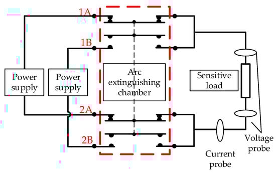
Figure 1.
Circuit topology of dual power supply switching.
2.2. Basic Principle of High-Speed Contactor
The switching type high-speed contactor is shown in Figure 2, which is divided into two parts: the arc extinguishing chamber and the actuator. The arc extinguishing chamber is mainly composed of four groups of contacts, corresponding to the above circuit topology. Actuator action can complete the separation of two sets of contacts and the closing of the other two sets of contacts. In addition, the arc extinguishing chamber is equipped with four permanent magnets to form a transverse magnetic field to accelerate the arc extinguishing.
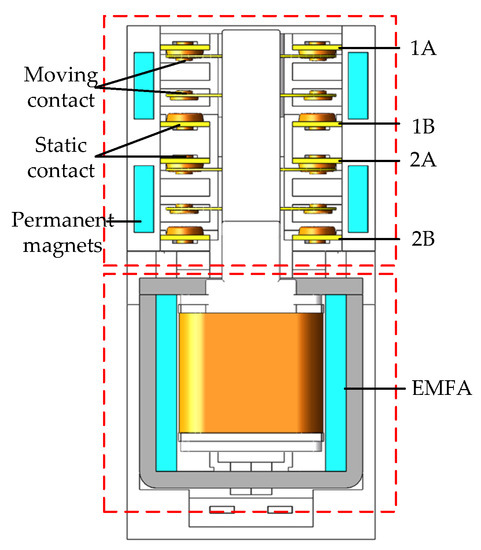
Figure 2.
Schematic diagram of the novel contactor structure.
The contactor is driven by EMFA. The schematic diagram of EMFA is shown in Figure 3. EMFA is composed of a top cover, yoke, static iron core, permanent magnet, moving iron core, and coil. Among them, the steady-state holding force is provided by the moving iron core. The transient driving force is provided by the coil. The permanent magnet provides the magnetic field, and the coil excitation will generate ampere force to drive the EMFA to move.
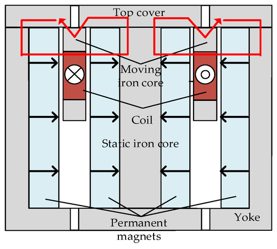
Figure 3.
Schematic diagram of the EMFA.
Refer to Figure 2 for the mechanical design of the contactor. The switch from A to B is taken as an example, and the switch topology is shown in Figure 1. The EMFA coil is energized to drive the coil former and the moving iron core to move. The coil former will drive the contact to move to complete the separation of the A road. When the A circuit is separated, an arc is generated, and as the contacts are gradually separated, the arc is gradually extinguished. After the arc is extinguished, circuit B is connected, and then the actuator action is completed. The contactor movement ends.
The ferromagnetic material of the contactor is DT4E, the permanent magnet material is N45, the residual magnetic flux density of the permanent magnet is 1.3 T, the contact piece material is beryllium copper, and the contact material is AgSnO2.
3. Basic Mathematical Model
3.1. Principle of Equivalent Magnetic Circuit Simulation
The electromagnetic characteristic simulation of EMFA is essentially to calculate the relationship between driving force, flux linkage, displacement, and current. The equivalent magnetic circuit model of EMFA is shown in Figure 4.
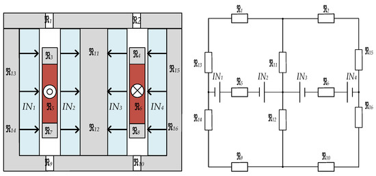
Figure 4.
EMFA equivalent magnetic circuit diagram.
The magnetic flux ϕ of the main magnetic circuit is an important parameter for the steady-state and transient calculation of the actuator. It can be seen from Figure 4 that the main magnetic circuit of the actuator is composed of four branches, and the four magnetic circuits are split and calculated according to the superposition theorem. Taking the lower left branch as an example, the magnetic circuit consists of excitation sources IN1, IN2, and magnetoresistor ℜ5, ℜ12, ℜ9, and ℜ14. The excitation source permanent magnet magnetic potential and magnetic resistance are as follows:
Among them, Hc is the coercivity of the permanent magnet, hm is the thickness of the permanent magnet, Br is the remanence, and S is the magnetic surface area of the permanent magnet. The calculation equation of ℜ5 is:
Among them, Ra is the magnetic resistance of the air gap between the permanent magnets, and Rm is the magnetic resistance of the permanent magnets. During the movement, the moving iron core is not in the holding position. It can be known from the magnetic circuit rule:
Since the moving iron core is in parallel with the working air gap during the movement, the magnetic flux of the moving iron core becomes the main component of magnetic leakage. Therefore, the magnetic leakage coefficient can be approximately expressed as:
According to Equation (4), it can be obtained that the permanent magnet generates the magnetic flux in one of the four magnetic circuits. Among them, dy is the height of the permanent magnet, and dd is the height of the moving iron core. In the holding position, the moving iron core is connected in parallel with the air gap. At this time, the magnetic flux passing through the moving iron core is:
The total flux linkage ψ is related to the moving position x and the excitation current i(t). The total flux linkage is decomposed into the flux linkage generated by the permanent magnet and the flux linkage generated by the coil.
As shown in Figure 5, the black solid line in Figure 5a is the direction of the magnetic flux generated by the permanent magnet, which consists of four independent main magnetic circuits, each of which passes through a working air gap. The dotted line in Figure 5b is the direction of the magnetic flux generated by the coil excitation, which is mainly looped by ferromagnetic materials. Regarding the permanent magnet flux linkage of the actuator, it is the flux linkage in the part of the static iron core wrapped in the center of the coil. The magnetic flux passing through the static iron core is bounded by the central axis of symmetry, and the upper half is upward and the lower half is downward, so a part of the permanent magnet flux linkage cancels each other. Taking the opening position as an example, the value of the flux linkage generated by the permanent magnet is equal to the opposite number of the flux of the permanent magnet above the coil multiplied by the number of turns of the coil. The magnetic flux of the permanent magnet above the coil is shown by the red line in Figure 5a.
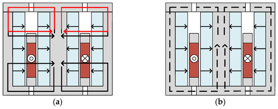
Figure 5.
Permanent magnet flux and coil flux. (a) Permanent magnet flux, (b) coil flux.
It is considered that the magnetic flux generated by permanent magnets per unit height is the same, and the flux linkage generated by permanent magnets satisfies the following relationship:
where dx is the stroke of the actuator, x is the position of the coil movement, dy is the height of the permanent magnet, ϕy is the total magnetic flux of one of the four magnetic circuits generated by the permanent magnet in Figure 5a, N is the number of turns of the coil, and ψy is the initial flux linkage of the actuator when x = 0. The coil excitation flux satisfies the relationship:
The permeability is fitted by the Froelich equation:
Then, the driving force of EMFA is calculated, and the resultant force on the moving part is as follows:
The resultant force is composed of the ampere force provided by the coil. The magnetic flux density B, which provides ampere force, can be calculated by Equation (4). When calculating the holding force, it is necessary to calculate the magnetic flux through the moving iron core by Equation (6). When the ampere force is less than the holding force, the EMFA does not move, and Ff is the contact force calculated by Adams.
Regarding the motion process of EMFA as the discharge process of capacitance to resistance and inductance, its motion process can be described by the voltage balance equation and the D’Alembert equation of motion [10].
In the formula, when ξ = 0 is the excitation phase, and when ξ = 1 is the movement phase. Uc is the capacitor voltage, ψ is the flux linkage, i is the current, c is the capacitance, v is velocity, m is mass, F is force, x is position, and R is the electric conductance of the coil. The diode short-circuits the capacitor during the freewheeling process, so the impact of the capacitor on the circuit is ignored during the freewheeling process. Compared with the finite element calculation, the equivalent magnetic circuit model improves the calculation speed.
3.2. Principle of Mechanical Dynamics Simulation
The dynamics simulation is mainly carried out through Adams. Adams automatically establishes Lagrangian equations of motion during movement [6].
where K is the kinetic energy of the object, q is the generalized coordinate system, used to describe the position and orientation of the object, ψ is the constraint equation of the system, λ is the Lagrangian multiplier, F is the force on the object, the subscript i represents the number of constraints, and the subscript j represents the number of rigid bodies.
The contact of the rigid body is solved by the Poisson model, and Adams/Solver uses the augmented Lagrangian multiplier to correct the contact force. The constraint condition that the contact force satisfies is:
In the formula, g is the penetration of two objects, Fn is the normal contact force, p is the penalty factor, k is the number of iterations, and k > 1. The displacement, velocity, and other parameters in the system can be solved through the above equations.
3.3. Principle of Magnetohydrodynamic Simulation
This paper mainly uses the magnetohydrodynamic model to simulate the arcing characteristics of the contactor. Since there is no equation related to the electromagnetic field in Fluent, it is necessary to carry out secondary development of Fluent. The governing equations in Fluent can be described using Navier–Stokes equations, which are divided into instantaneous terms, convection terms, diffusion terms, and source terms [19]. The electromagnetic field equation can be loaded into Fluent by modifying the source term in the equation. The magnetohydrodynamic model combines the thermal field, electromagnetic field, and airflow field to calculate. The physical parameters of the arc are the bridges between multiple fields.
In Table 1, u is fluid velocity, j is current density, A is magnetic potential, B is magnetic flux intensity, h is enthalpy, ϕ is electric potential, E is electric field intensity, p is pressure, and qrad is the radiation term. λ, Cp, σ, and η are thermal conductivity, specific heat capacity, electrical conductivity, and the viscosity coefficient, respectively.

Table 1.
Magnetohydrodynamics control equation.
4. Modeling and Simulation
The simulation model of the contactor includes two parts: the electromechanical model and the magnetohydrodynamic model. The overall process of electromechanical coupling is as in Figure 6. Current and capacitor voltage are used to calculate the flux linkage and then calculate the current through the initial flux linkage and the initial displacement. Then, the driving force is calculated according to the current and position. After the driving force enters Adams, the displacement at the next time point is calculated. The loop iteration is thus carried out. The magnetohydrodynamic model is mainly simulated through the secondary development of Fluent, and the velocity characteristics of the electromechanical coupling output are input into Fluent. The arcing time output by Fluent is compared with the flight time of the electromechanical model to judge the effectiveness of the switching.
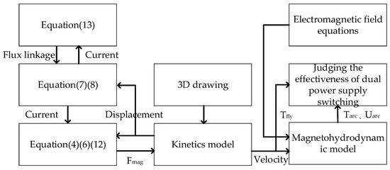
Figure 6.
Simulation framework.
Equations (7) and (8) calculate the flux linkage of the permanent magnet and coil, respectively. Equations (4), (6) and (12) are used to calculate the electromagnetic force of the electromagnetic device. Equation (13) solves the flux linkage based on voltage and current. The dynamic model is used to calculate the reaction force of the contact. The magnetohydrodynamic model inputs velocity characteristics and electromagnetic field equations to simulate the transient characteristics of the arc.
The equivalent magnetic circuit model and the dynamic model run in Matlab, while the magnetohydrodynamic model runs in Fluent. After the contact reaches the initial distance in Matlab, the serial operation starts. As shown in Figure 7, this article uses two flag bits (M_FLAG and F_FLAG) to implement serial operations. When the flag bit is 1, the corresponding program operates. When the flag bit is 0, the corresponding program waits. When Matlab changes M_FLAG to 0 and F_FLAG to 1 after running and when Fluent detects that F_FLAG is 1, it will start computing. After the Fluent operation, M_FLAG becomes 1 and F_FLAG becomes 0, so as to realize serial operation. As shown in Figure 7b, this article also provides specific details of electromagnetic calculations.
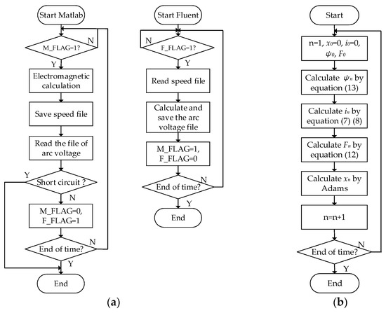
Figure 7.
Flow chart. (a) Matlab and Fluent serial operation flow chart. (b) Electromagnetic calculation flow chart.
Through data transmission, the model built in this article can determine whether a power supply short-circuit occurs during power switching. This serial operation method does not require manual operation, saving time and cost. Compared with independent operations, the multi-model joint method completes the data interaction between each time step. In addition, due to the establishment of data interaction between software, the model has scalability.
4.1. Electromechanical Co-Simulation
Based on the above-mentioned novel EMFA structure topology, an equivalent magnetic circuit model is established, and the current and driving force are calculated according to the equation of driving force, flux linkage, displacement, and current.
Matlab is used to co-simulate the above model with Adams and the dynamic characteristics of EMFA are solved according to the driving force. Then, the displacement output is used to iterate the calculation of the current and driving force at the next time point. Co-simulation calculation results are shown in Figure 8.
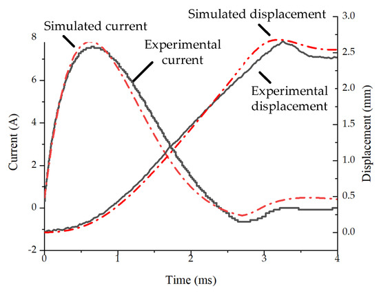
Figure 8.
Comparison of simulation and experiment.
As shown in Figure 8, the secondary rise of current is better represented. When the contact is in contact, the contact will produce a reaction force to the EMFA, causing the movement speed to drop. It can be seen from Equation (7) that the decrease in the movement speed will cause the flux linkage change rate produced by the permanent magnet to decrease. From Equation (13), it can be seen that the decrease in flux linkage rate will eventually lead to a secondary increase in current. The bounce of the contactor is also calculated by Adams.
When the displacement reaches 0.5 mm, the A-way contact is separated. When the displacement reaches 2 mm, the B-way contact is closed. It can be seen from the simulation and experimental results that the flight time from the separation of the A-way contact to the B-way closing is 1.4 ms. Therefore, in order to ensure the effectiveness of switching, the arcing time should be less than 1.4 ms.
4.2. Magnetohydrodynamic Simulation
This paper is based on the finite element software Fluent to simulate the arcing characteristics of the contactor. Since the electromagnetic field cannot be calculated in Fluent, the electromagnetic field equation is input in the form of secondary development. As shown in Figure 9a, permanent magnets are used to apply a transverse magnetic field parallel to the movable contact to the arc extinguishing chamber. Driven by the transverse magnetic field, the arc is gradually elongated into the insulating grid, and finally extinguished.
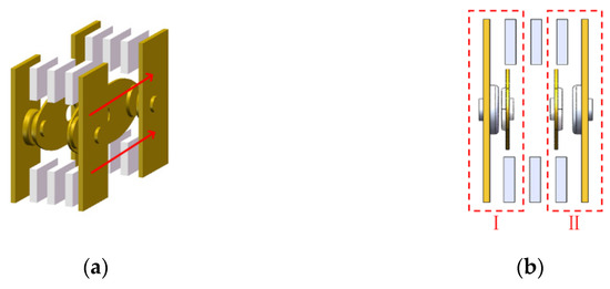
Figure 9.
Simulation model of interrupter. (a) 3D interrupter model, (b) Simulation perspective of interrupter.
Since the moving contact is a bridge-type, the current enters the moving contact through the static contact and then flows into the other moving contact. Therefore, the two contact currents on a single bridge contact have opposite current directions. Under the condition of the same magnetic field drive, the arc movement direction is opposite. One can make the two arcs move in two opposite directions in the side view.
As shown in Figure 10, the simulation calculations are performed for 410V13A, 240V21A, and 188V28A. Since the currents at both ends of the moving contact plate are in opposite directions, the arc moves in two different directions. Therefore, the arc shape and arcing time can be analyzed based on the temperature cloud diagram.
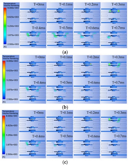
Figure 10.
Simulation diagram of arc temperature. (a) Temperature diagram at different moments under 410 V/13 A, (b) Temperature diagram at different moments under 240 V/21 A, (c) Temperature diagram at different moments under 188 V/28 A.
As shown by the simulated temperature cloud diagram, the magnetohydrodynamic simulation gives an initial arc column at the initial position. One can calculate the dynamic change process of the arc column driven by the permanent magnet magnetic field. After entering the insulating grid, the arc rapidly elongates and cools, and then gradually dissipates.
5. Experiment and Analysis
On the basis of the above simulation, the principle prototype was made, and the switching experiment was completed. As shown in Figure 1, the circuit is set to 10V0.1A for switching experiments to test the mechanical switching characteristics of the contactor. Voltage probes are used to measure the voltage of the coil and the load, and a current probe is used to measure the current of the coil. It can be seen from the load voltage that the contact bounce of the contactor is less than 0.5 ms. This is because the air gap of the actuator of the contactor remains unchanged during the closing process, and the closing collision force will not increase sharply. It is worth mentioning that it is not accidental that the bounce time is less than 0.5 ms. As shown in Figure 11, the bounce time of the contactor is basically stable at a fixed value.
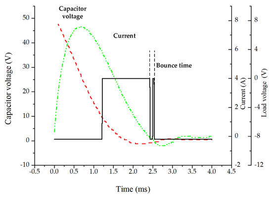
Figure 11.
Low load switching waveform.
The test coincides with the simulation, which verifies the accuracy of the simulation and the effectiveness of the contactor. It is worth mentioning that the experimental data in Figure 12 are the arc voltage curve corresponding to the median arcing time. The experimental conditions are similar to those shown in Figure 1. One can change the voltage of the power supply and the resistance of the load and adjust the loop power to 5000 W for experimentation.
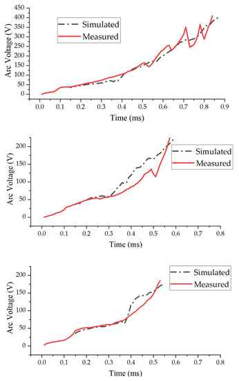
Figure 12.
Comparison diagram of arc voltage simulation and experiment.
In Figure 12, the output voltage and current of the power supply are 410V13A, 240V21A, and 188 V/28 A, respectively. As shown in Figure 12, there is a certain error between the simulated arc voltage and the actual arc voltage. The simulation and experiment produced a certain error in the second half. This may be caused by not considering the metal vapor in the arc. The metal vapor in the arc will increase the electrical conductivity of the arc, so that the simulated arc voltage should be reduced. The above reasons cause errors between the simulation and experiment. The authors will further improve the simulation model in future research. However, the difference between the simulated arcing time and the actual arcing time is small. The magnetohydrodynamic model is mainly used to evaluate the arcing time of the contactor, so the error between the simulation and the actual is acceptable.
In addition to testing the voltage characteristics of the contactor, this article also uses a high-speed camera to photograph the changes in the shape of the arc. Since the permanent magnet blocks the shooting angle of view, this article uses the frontal angle of view shown in Figure 13a for shooting. The arc evolution process of the four fractures can be seen from the image. The brightness of the two fractures on the right is significantly higher than that on the left. This is due to the fact that the arc is stretched outward due to the action of the transverse magnetic field. The arc on the left evolves inward, and the light is darker due to the blocking of parts. It is found that the simulated arcing time is slightly shorter than the actual arcing time. This is because the simulation does not consider the arc starting phase. In addition, there are tolerances due to prototype production. Due to the inevitable tolerances of assembly and parts, the opening distance of each fracture has an error within 0.05 mm. It can be seen from the image that the arcs of the four fractures are not generated at the same time. Therefore, in the process of prototype production, the cumulative tolerance should be minimized here to enhance the consistency of the product. With the continuous increase in the contact distance, the arc gradually grows under the action of the magnetic field. When the arc voltage reaches near the power supply voltage, the current in the circuit is small, and the arc is gradually extinguished.
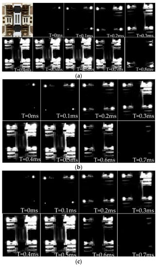
Figure 13.
Arc image high-speed photography. (a) High-speed photography at different moments under 410 V/13 A, (b) High-speed photography at different moments under 240 V/21 A, (c) High-speed photography at different moments under 188 V/28 A.
It is worth mentioning that the simulation does not consider the arc starting process, so there is an initial arc column at the beginning of the simulation. Therefore, the simulated arcing time should be added to the fixed time T0 for the contact separation to the initial arc column position.
6. Conclusions
This paper proposes a new type of contactor and completes related simulations and experiments. Through co-simulation, the power switching phenomenon of the contactor is simulated. The speed characteristics are output by coupling the electromagnetic characteristics and the mechanical dynamic characteristics, and then input into the magnetohydrodynamic model to calculate the arcing time. The effectiveness of dual power supply switching is judged by comparing flight time and arcing time. In this paper, a prototype is made and related experiments are carried out on the basis of simulation, and the following conclusions are summarized.
(1) On the basis of the novel structure topology, the electromagnetic calculation model of the actuator with a constant air gap is established through the equivalent magnetic circuit model, and the calculation is coupled with the mechanical dynamics model. Compared with finite element, the calculation speed is improved.
(2) The magnetohydrodynamic model is established, and the arcing characteristics of the bridge contacts are analyzed. The serial calculation can automatically determine whether the power supply will be short-circuited.
(3) Experimental tests verify the accuracy of the electromechanical model and the model of magnetic fluid. This paper proposes a simulation model that plays a guiding role in the design of contactors for power switching. Experiments show that the contactor can complete 5000 W power switching within 3 ms, which also verifies the practicability of the new contactor.
Author Contributions
Conceptualization, G.W. and E.D.; methodology, G.W.; software, S.X.; validation, Y.W., L.Z.; formal analysis, S.X.; investigation, L.Z.; resources, J.Z.; data curation, G.W. All authors have read and agreed to the published version of the manuscript.
Funding
This research was funded by the National Natural Science Foundation of China, Grant No. 51877026.
Institutional Review Board Statement
Not applicable.
Informed Consent Statement
Not applicable.
Conflicts of Interest
The authors declare no conflict of interest.
References
- Tian, B.; Mao, C.; Lu, J. 400 V/1000 kVA Hybrid Automatic Transfer Switch. IEEE Trans. Ind. Electron. 2013, 60, 5422–5435. [Google Scholar] [CrossRef]
- Mokhtari, H.; Dewan, S.B.; Iravani, M.R. Analysis of a static transfer switch with respect to transfer time. IEEE Trans. Power Deliv. 2002, 17, 190–199. [Google Scholar] [CrossRef]
- Geng, H.; Zhang, X.; Zhang, Y.; Hu, W.; Lei, Y.; Xu, X.; Wang, A.; Wang, S.; Shi, L. Development of Brushless Claw Pole Electrical Excitation and Combined Permanent Magnet Hybrid Excitation Generator for Vehicles. Energies 2020, 13, 4723. [Google Scholar] [CrossRef]
- Ro, J.; Bak, H.; Jung, H. Characteristic analysis and design of a novel lorentz force driving actuator for a molded case circuit breaker. IET Electr. Power Appl. 2015, 9, 1–9. [Google Scholar] [CrossRef]
- Fang, S.; Lin, H.; Ho, S.L. Magnetic Field Analysis and Dynamic Characteristic Prediction of AC Permanent-Magnet Contactor. IEEE Trans. Magn. 2009, 45, 2990–2995. [Google Scholar] [CrossRef]
- Fang, S.; Lin, H.; Ho, S.L. Transient Co-Simulation of Low Voltage Circuit Breaker with Permanent Magnet Actuator. IEEE Trans. Magn. 2009, 45, 1242–1245. [Google Scholar] [CrossRef]
- Shu, L.; Wu, L.; Wu, G.; Wu, Z. A Fully Coupled Framework of Predicting the Dynamic Characteristics of Permanent Magnet Contactor. IEEE Trans. Magn. 2016, 52, 1–7. [Google Scholar] [CrossRef]
- Tang, L.; Xu, Z.; Bala, V. Contactor Modeling Technology Based on an Artificial Neural Network. IEEE Trans. Magn. 2018, 54, 1–8. [Google Scholar]
- Tang, L.; Han, Z.; Xu, Z. Neural Network-Based Co-Simulation Technology for Intelligent Contactors. IEEE Trans. Magn. 2020, 56, 1–8. [Google Scholar]
- Wang, X.; Lin, H.; Fang, S. Dynamic performance analysis of permanent magnet contactor with a flux-weakening control strategy. J. Appl. Phys. 2011, 109, 07E707. [Google Scholar] [CrossRef] [Green Version]
- Espinosa, A.G.; Ruiz, J.R.; Morera, X.A. A Sensorless Method for Controlling the Closure of a Contactor. IEEE Trans. Magn. 2007, 43, 3896–3903. [Google Scholar] [CrossRef]
- Wang, X.; Lin, H.; Ho, S.L.; Fang, S.; Jin, P. Analysis of Dynamic Characteristics of Permanent Magnet Contactor With Sensorless Displacement Profile Control. IEEE Trans. Magn. 2010, 46, 1633–1636. [Google Scholar] [CrossRef]
- Fang, S.; Chen, Y.; Ni, H.; Lin, H.; Wang, X.; Zhu, B.; Zhang, Y. A Novel Breaking Strategy for Reduced Response Time of Electromagnetic Contactor by Reverse Voltage Application. Energies 2019, 12, 789. [Google Scholar] [CrossRef] [Green Version]
- Dong, E.; Qin, T.; Wang, Y.; Duan, X.; Zou, J. Experimental Research on Speed Control of Vacuum Breaker. IEEE Trans. Power Deliv. 2013, 28, 2594–2601. [Google Scholar] [CrossRef]
- Tang, L.; Han, Z.; Xu, Z. A Sequential Adaptive Control Strategy for the Contact Colliding Speed of Contactors Based on Fuzzy Control. IEEE Trans. Ind. Electron. 2021, 68, 6064–6074. [Google Scholar] [CrossRef]
- Lin, H.; Wang, X.; Fang, S.; Jin, P.; Ho, S.L. Design, Optimization, and Intelligent Control of Permanent-Magnet Contactor. IEEE Trans. Ind. Electron. 2013, 60, 5148–5159. [Google Scholar] [CrossRef]
- Ruiz, J.R.; Espinosa, A.G. A Novel Parametric Model for AC Contactors. IEEE Trans. Magn. 2008, 44, 2215–2218. [Google Scholar] [CrossRef]
- Li, H.; Cui, L.; Ma, Z.; Li, B. Multi-Objective Optimization of the Halbach Array Permanent Magnet Spherical Motor Based on Support Vector Machine. Energies 2020, 13, 5704. [Google Scholar] [CrossRef]
- Ma, R.; Rong, M.; Yang, F.; Wu, Y.; Sun, H.; Yuan, D.; Wang, H.; Niu, C. Investigation on Arc Behavior During Arc Motion in Air DC Circuit Breaker. IEEE Trans. Plasma Sci. 2013, 41, 2551–2560. [Google Scholar] [CrossRef]
- Yin, J.; Wang, Q.; Li, X. Simulation Analysis of Arc Evolution Process in Multiple Parallel Contact Systems. IEEE Trans. Plasma Sci. 2018, 46, 2788–2793. [Google Scholar] [CrossRef]
- Rong, M.; Ma, R.; Chen, J.; Hou, C.; Sun, Y. Numerical Investigation on Arc Behavior in Low-Voltage Arc Chamber Considering Turbulence Effect. IEEE Trans. Plasma Sci. 2014, 42, 2716–2717. [Google Scholar] [CrossRef]
- Chen, F.; Xu, Y.; Cao, Z.; Wang, Z.; Ma, X. Hybrid Kinetic-MHD Simulations of Vacuum Arc Using Field-Circuit Coupling Method. IEEE Trans. Magn. 2020, 56, 1–4. [Google Scholar] [CrossRef]
Publisher’s Note: MDPI stays neutral with regard to jurisdictional claims in published maps and institutional affiliations. |
© 2021 by the authors. Licensee MDPI, Basel, Switzerland. This article is an open access article distributed under the terms and conditions of the Creative Commons Attribution (CC BY) license (https://creativecommons.org/licenses/by/4.0/).