Article

Bragg Mirrors for Thermal Waves

by
Angela Camacho de la Rosa
1,†,
David Becerril
2,†,
María Guadalupe Gómez-Farfán
1,† and
Raúl Esquivel-Sirvent
1,*,†
1
Instituto de Física, Universidad Nacional Autónoma de México, Apartado Postal 20-364, Ciudad de México 01000, Mexico
2
Istituto di Struttura della Materia, Consiglio Nazionale delle Ricerche (CNR), Via Fosso del Cavaliere 100, 00133 Rome, Italy
*
Author to whom correspondence should be addressed.
These authors contributed equally to this work.
Energies 2021, 14(22), 7452; https://doi.org/10.3390/en14227452
Submission received: 9 October 2021 / Revised: 30 October 2021 / Accepted: 1 November 2021 / Published: 9 November 2021
(This article belongs to the Special Issue Nanoscale and Microscale Heat Transfer)

Abstract

:
We present a numerical calculation of the heat transport in a Bragg mirror configuration made of materials that do not obey Fourier’s law of heat conduction. The Bragg mirror is made of materials that are described by the Cattaneo-Vernotte equation. By analyzing the Cattaneo-Vernotte equation’s solutions, we define the thermal wave surface impedance to design highly reflective thermal Bragg mirrors. Even for mirrors with a few layers, very high reflectance is achieved (>90%). The Bragg mirror configuration is also a system that makes evident the wave-like nature of the solution of the Cattaneo-Vernotte equation by showing frequency pass-bands that are absent if the materials obey the usual Fourier’s law.

Graphical Abstract

1. Introduction

The assumption of a causal response in the Fourier law of heat transport introduces a time delay between the temperature gradient and the heat flux. This time delay implies a finite velocity of heat propagation, and the temperature and heat flux obey a hyperbolic partial differential equation known as the Cattaneo-Vernotte equation (CVe) [1,2,3,4,5]. As a hyperbolic equation, its solutions are wave-like and it is possible to have heat or temperature waves that satisfy particular dispersion relations [6,7].
Several experiments have explored the non-Fourier behavior of heat transport in a variety of systems, such as granular media [3,8], wet sands [9], organic materials [10], blood and porcine muscle [11], and processed meat [12]. Skin bio-thermomechanics and bioheat transfer mechanisms also follow a non-Fourier behavior [13,14,15]. Recently, the wave-like behavior was shown experimentally in bulk Ge for temperatures between 7 K and room temperature as well as in graphite, opening a new potential applications for heat waves [16,17].
For wave-like behavior, proposals to control the heat flux have been reported that are inspired by systems similar to those used in optics or acoustics. For example, thermal cloaking from coated spheres mimicking a metamaterial has been proposed [18] as well as thermal or temperonic crystals [19,20]. The latter are made of an array of layers forming a periodic one-dimensional system or superlattice. Similar work was conducted by Gandolfi using a dual-phase lag equation that introduces an extra term (third order derivative of the temperature) in the CVe [20]. Previously, CVe was solved for a layered system under a pulsed heat source determining the effective or average thermal properties [21]. Chen [19] used the CVe in a superlattice and calculated the dispersion relation using Bloch’s theorem. Ballistic-diffusive models for heat transport in superlattice used the Guyer–Krumhansl equation since the thickness of the layers is comparable to the mean free path of the phonons [22].
Superlattices have the advantage of being simple to fabricate and experimentally characterizable. Their use in heat transport has been limited to the case of Fourier heat conduction. Using a periodic structure of alternate layers of porous Si due to the ensuing photonic band structure, it is possible to show that heating in light band gaps decreases the temperature of the system [23,24]. The thermal conductivity of superlattices comprising different semiconductors have been studied by using the Boltzmann transport equation and could have possible applications in thermoelectric and optoelectronic devices [25].
For a finite system, Bloch’s theorem is no longer applicable, and while the presence of the bounding surfaces will break the periodicity, some of the main features of the infinite superlattice remain. For example, the reflectivity will show regions of high and low values in the frequency regions of the allowed and forbidden bands of the dispersion relation depending on the length of the superlattice [26,27,28]. The observed band gaps or quasi-band gaps are due to interference effects of the waves in the superlattice. A particularly useful finite system is a Bragg mirror made of alternate layers of high and low dielectric constants [29] or acoustic impedances [30,31].
In this paper, we demonstrate the possibility of Bragg mirrors for thermal waves that are solutions to the Cattaneo-Vernotte equation. The mirrors are made of alternate layers of two different materials with different thermal properties. Even for mirrors made of a few bilayers, a high reflection of the thermal waves is achieved. The changes in the heat flux into the Bragg mirror as a function of frequency are only possible with wave-like behavior. Further refinement of the flux can be achieved by introducing defects into the mirror. In addition to presenting a system to show the wave-like nature of the solution of the CVe, we discuss possible applications in heat management.

2. Thermal Waves—Cattaneo-Vernotte Equation

In this section, we review the basic characteristics of thermal waves as solutions of the Cattaneo-Vernotte equation (CVe). Consider a medium with thermal conductivity κ [W m 1 K 1 ], mass density ρ [kg m 3 ] and specific heat capacity at constant volume c v [J kg 1 K 1 ]. The CVe arises when there is a time delay τ between the application of a temperature gradient T ( r , t ) and the ensuing heat flux q ( r , t ) , resulting in the following equation [1,2,3,4].
q ( r , t ) + τ q ( r , t ) t = κ T ( r , t ) .
Taking the divergence of Equation (1) and considering the balance equation of the thermal energy density u ( r , t ) without sources given by ρ c v T t + · q = 0 yields the following.
2 T ( r , t ) = 1 α T ( r , t ) t + 1 υ 2 2 T ( r , t ) t 2 .
The thermal diffusivity is defined as α = κ / ρ c v . The parameter υ = α / τ is identified as the propagation speed of the thermal perturbation [32,33]. In the limit τ 0 , the speed υ goes to infinity, and Equation (1) reduces to the usual Fourier law for heat conduction [34,35,36]. To further explore the wave like-nature of CVe, we solve Equation (2) in Cartesian coordinates for one dimension; this is the following.
2 T ( x , t ) x 2 = 1 α T ( x , t ) t + 1 υ 2 2 T ( x , t ) t 2 .
We assume a solution of the form T ( x , t ) = e i ω t T ^ ( x ) , with ω being the angular frequency, resulting in the following:
d 2 T ^ d x 2 = k 2 ( ω ) T ^ ( x ) ,
to finally obtain the following solution:
T ( r , t ) = A e i ( k · r ω t ) + B e i ( k · r + ω t ) ,
where the complex wavevector is as follows:
k = ω υ 2 + i ω α .
The temperature profile Equation (5) assumes a real frequency and a complex wavevector. The other possibility is to have k real and a complex frequency. Our choice of solution is based on the analogy of Equation (2) with the telegrapher equation of electrodynamics [37] where the external fields are time-harmonic. In our case, the temperature field is assumed as time-harmonic, for example, heating with an intensity modulated laser [38] or having a time-harmonic heat source. This choice will help us compare our results with the case of a Fourier material that is also periodically excited [39]. The difference between the choice of real or complex frequency and the ensuing dispersion relation is discussed by Gandolfi et al. [7].
We point out two limits of interest: (1) when ω τ < < 1 , the CVe goes to the usual diffusion equation; and (2) when ω τ , the wavenumber k becomes real, and the temperature profile behaves as a non-damped wave equation.
From wavenumber k of Equation (6), we define the penetration length as δ = 1 / Im ( k ) , and the wavelength is λ = 2 π / Re ( k ) . For the CVe, a characteristic length scale is = 4 π α / ω , and we can write δ c v = 2 / λ c v . If 0 < λ < , then we are in a highly damped regime. Otherwise, the wavelike behavior dominates with little damping. In the Fourier law, we have the relation δ f = λ f / 2 π , which implies that penetration length is smaller than the wavelength and decreases before it reaches a period; thus, the damped behavior dominates.
The heat flux for the CVe is obtained by replacing Equation (5) in Equation (1) as follows:
q ( r , t ) = i K ( ω ) k k ^ A e i ( k · r ω t ) B e i ( k · r + ω t ) ,
where the modified thermal conductivity is given by K ( ω ) = κ 1 i ω τ . This allows us to define Y ( ω ) = i K ( ω ) k as the thermal admittance, and it can be expressed as follows.
Y ( ω ) = κ υ τ 1 1 + i / ω τ .
The reciprocal of the admittance defines the thermal impedance [40], Z i ( ω ) = T / q i · n ^ , where n ^ is the normal vector relative to the ith interface.

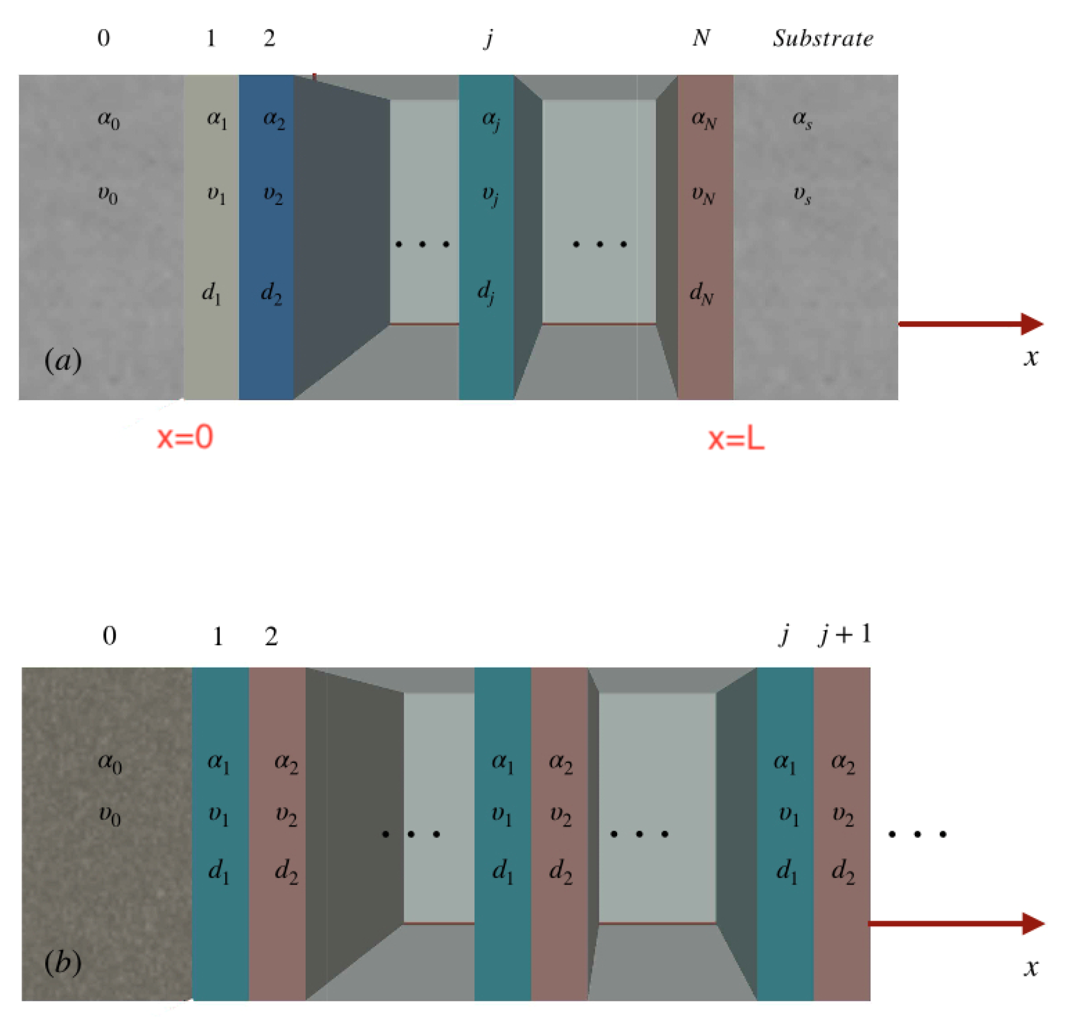
3. Thermal Superlattice

Consider an array of N layers in a Cartesian coordinates system ( x , y , z ) where the x-axis is perpendicular to the interfaces. Each layer is of width d j with thermal properties α j , υ j . The first interface is at x 0 = 0 , and the last layer interface is at x N = d 1 + + d N = L . Outside the layered structure, for x < x 0 , there is a medium with thermal properties α 0 , υ 0 ; moreover, for x > x N , there is a substrate defined by α s , υ s , as shown in Figure 1a. We will consider normal incidence; thus, q ( r , t ) = q ( x , t ) x ^ .
Following the usual transfer matrix formalism, the fields at the first interface x = x 0 are related to those at the final x = x L as follows.
T ( L ) q ( L ) = M N M N 1 M 1 T ( 0 ) q ( 0 ) .
Here, the matrix M j is given by the following [21,41]:
M j = cos ( k j d j ) 1 Y j sin ( k j d j ) Y j sin ( k j d j ) cos ( k j d j ) 1 R j , j + 1 0 1 ,
where R j , j + 1 is the interfacial or Kapitza resistance between the jth and j + 1 interfaces.
The matrix M = j = 0 N 1 M N j in Equation (9) is known as the associated transfer matrix which transfers the fields, in this case temperature and heat flux, through a given domain [42]. The reflection coefficient r for the finite system is expressed in terms of the surface admittance of the layered structure Y as follows [26].
r = Y 0 Y Y 0 + Y .
Here, Y 0 is the admittance of the initial medium, Y is written in terms of the admittance of the substrate Y s and the components of the associated transfer matrix is as follows [26,42].
Y = M 21 Y s M 11 Y s M 12 M 22 .
We will consider a Bragg mirror made by repeating a unit cell with two materials m 1 and m 2 . If we have n unit cells, the total transfer matrix is M = ( M 2 M 1 ) n . The diagram is shown in Figure 1b. If the number of cells is infinite, we obtain a superlattice with a translational invariance for x > 0 .
We want to compare the reflectivity r of the finite and infinite superlattice. For the infinite case, we use Bloch’s theorem [19,20], which establishes the dispersion relation of the Bloch wavenumber Q as cos ( p Q ) = 1 2 T r ( M ) , where p = d 1 + d 2 is the period of the superlattice, and M = M 2 M 1 is the transfer matrix of the unit cell. In the infinite case, the reflectivity r will be given by Equation (11) but with admittance of the following.
Y = M 12 i ( e i Q p M 11 ) .
The calculation of the transfer matrix requires the values of the interfacial resistance. However, the contribution is negligible for our particular problem. For the materials we discuss in this work, for which its value can be similar to the contact between soft–matter or liquid–liquid interfaces [43,44], the values of the interfacial thermal conductance G = 1 / R are in the range G [ 1.05 , 3 ] × 10 6 [Wm 2 K 1 ]. For these values, the interfacial thermal resistance is negligible when calculating the total transfer matrix of the system. This is because the Kapitza length l k = κ R is much smaller than the thickness of the layers.
There is an important difference between the CVe and other wave phenomena, such as electromagnetic or acoustic. The reflectance is defined as the ratio of the reflected power to the incident power of a wave [45]. For example, in the electromagnetic case, the power is measured integrating the time-average Poynting vector, and it is related to the square of the electric field | E | :
R = | E r | 2 | E i | 2 = | r E i | 2 | E i | 2 = | r | 2 ,
where | E i | and | E r | are the incident and reflected fields, respectively. In the thermal case, the power is measured by the heat flux, which is linear with the temperature field, and the reflectance is as follows.
R = | q r | | q i | = | r T i | | T i | = | r | .
Since | r | 2 < | r | < 1 , by definition, the thermal wave reflectance is bigger than the reflectance of other waves, as will be shown later.

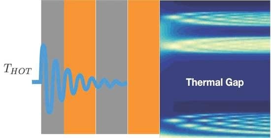
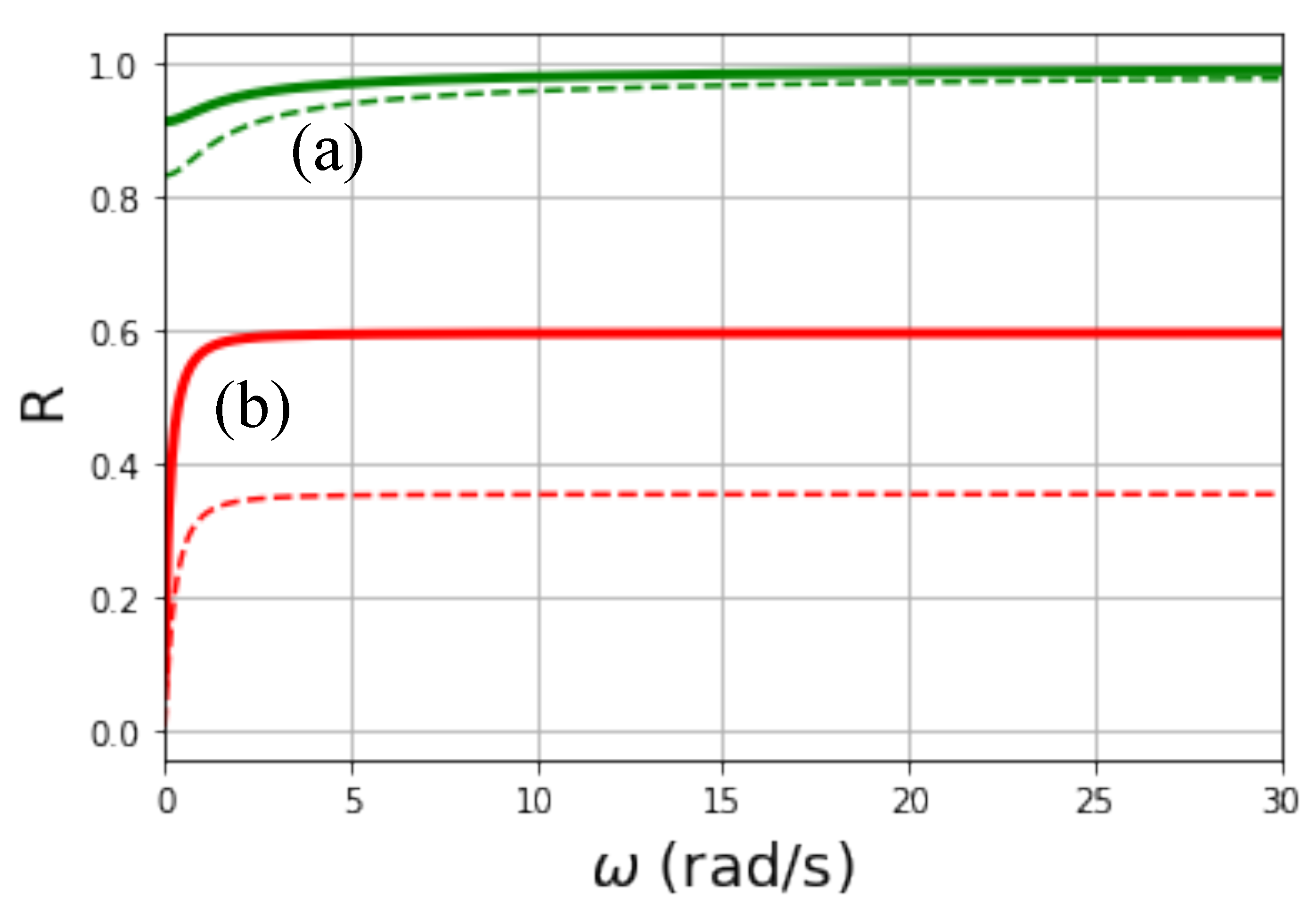
4. Thermal Bragg Mirrors

Optical Bragg mirrors are made of alternate layers of high and low index of refraction materials. The wave nature of the solution of the CVe is explored via a thermal Bragg mirror. We compute the heat flux q ( r , t ) · n ^ into the layered system.
To extend the definition to thermal wave, we consider three specific materials: aluminum [46] (Al) and two materials with thermal properties of biological tissue (epidermis and dermis) [13,19,47]. In Table 1, the thermal properties of these materials are listed. From the experimental point of view, materials with biological-like responses can be designed with specific thermal properties using gel-phantoms [48].
In order to illustrate the individual reflection properties of Al and dermis, consider a half-space made of each material in contact with a substrate made of a material with the properties of epidermis. In Figure 2, we show the reflectance R as a function of the frequency ω for each half-space system. The solid lines correspond to reflectance as R = | r | from Equation (15) and the dashed lines to R = | r | 2 as in other types of waves from Equation (14). The reflectance from Al (green line) exhibits a weak dependence on frequency reaching the maximum value of R = 1 at low frequencies; this material is a good conductor and has a very small relaxation time. The reflectance of dermis (red line) also reaches its maximum ( R = 0.6 ) at low frequencies although the relaxation time is larger than Al. This behavior allows us to reduce the frequency domain to take into account ( ω < 30 rad/s).
In addition to the reflectance, for the materials of Table 1, the penetration length δ of the thermal waves was calculated as a function of frequency. This is shown in Figure 3. The dotted lines indicate the asymptotic value δ 2 α / v derived from Equation (6) for large values of frequencies. We observe that at small frequencies, the limit value of δ is reached.
Thermal Bragg mirrors are made of alternate layers of two materials with different thermal admittance. As in the optical case, we expect a frequency dependence on R with high (low) values for different frequency ranges.
As a first case, we consider a thermal mirror made of alternate layers of material two (dermis) and material one (epidermis), shown in Table 1. Not including the incident and substrate layers, the unit cell that will be repeated follows the sequence m1-m2. The thickness of each layer is d = 100 μ m. In Figure 4a–c, we show reflectance R = | r | as a function of frequency for different numbers of unit cells. The blue solid line corresponds to R for the finite Bragg mirror, and the dashed red line corresponds to the semi-infinite periodic system calculated using Equation (13). Finally, Figure 4d presents a contour plot of normalized heat flux q · n ^ into the laminated system, normalized to the incident heat flux of magnitude q 0 . The vertical axis is the frequency and in the horizontal axis, the number of unit cells is shown. We observe that frequency regions of high reflectivity correlate with low values of heat flux. Notice that even with a few number of unit cells the rejection-band defined by a high reflectivity is obtained. The rejection-band can be clearly seen in Figure 4d and is delimited by the white-dotted line.
The reflectance in Figure 4 has the typical form of a periodic system band structure, which ultimately is a result of introducing a delay time in the heat conduction model of Equation (1). When solving the Fourier equation for the same system, frequency windows of high or low reflectance do not appear, instead a monotonous behavior for the reflectance and heat flux is obtained, as we show in Figure 5. In this figure, the same m1-m2 sequence was used as in the CV case and represents the diffusive limit for the Figure 4d. The choice of real frequencies induces an oscillatory behavior of the temperature, both in the Fourier and Cattaneo cases; despite this, the band-structure in the reflectance of the layered system appears only in Cattaneo’s solution.
We emphasize that the heat flux behavior in a periodic system which is analogous to the energy band structure of electrons in solids is a consequence of the CVe, and it is not predicted by Fourier’s law, as is shown in Figure 5. Furthermore, the frequency dependence on the reflectance is only obtained when solving the CVe and not the Fourier case.
For this reason, an experimental setup similar to the layered system studied in this work could be used to verify or discard the existence of thermal waves.

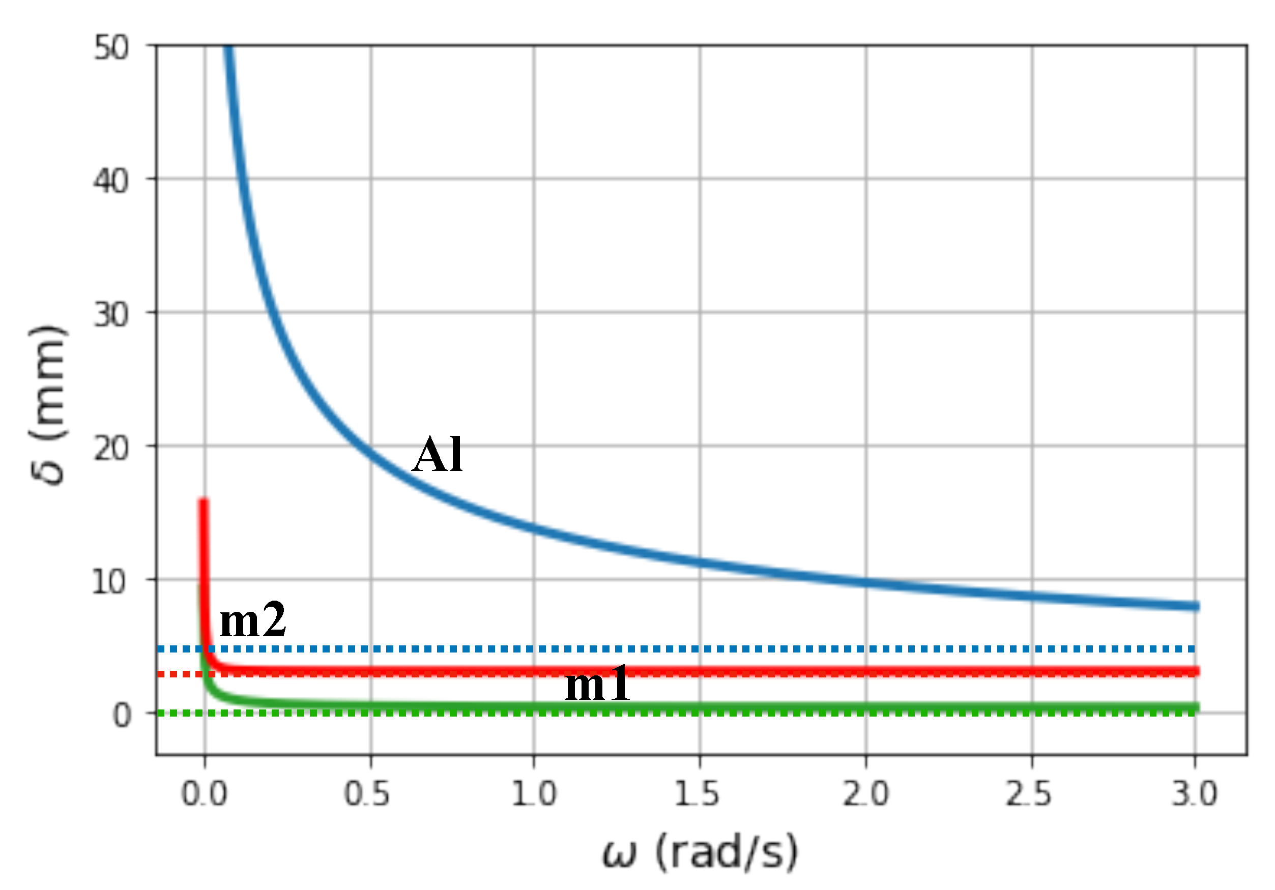
Tuning of the Thermal Reflectance

Having the stop or rejection band in a frequency window opens the possibility of fine-tuning the thermal reflectance and heat flux by modifying the unit-cells. For example, if we have the unit-cell constructed as m1-m2-Al-m2, where the second layer of material 1 is replaced by an Aluminum layer of thickness to 0.01 d = 1 μ m. In this case, the reflectance and normalized heat flux are presented in Figure 6.
As expected, new states appear and are indicated by shaded rectangles in Figure 6a–c. We observe that reflectance for n = 1 and n = 3 shows a good agreement with the semi-infinite periodic medium such that there are well defined frequency windows of high reflectance. However, for few unit cells, the narrowest frequency windows are not defined yet and appear until we use 15 unit cells, as is shown in Figure 6c; this is what we mean as fine-tuning of heat flux.
Metals have negligible relaxation times, follow Fourier’s law and are malleable; thus, they have the advantage of being easy to fabricate with a well defined thickness within the periodic structure. A comparison of Figure 4 and Figure 6 shows to what degree heat flux can be modified simply by adding an aluminum layer. The high reflectance region is subdivided into four narrower high reflectance regions. The thermal Bragg mirrors result from the contrast between the thermal properties of layer materials and the number of unit cells, analogous to the refractive index combination of optics Bragg mirrors.

5. Conclusions

In this paper, we showed the possibility of constructing Bragg mirrors for thermal waves that are a solution to the Cattaneo-Vernotte equation; it cannot be generated using Fourier’s law to model heat conduction. The mirrors are made of alternate layers of two different materials yielding a reflectance definition different from other waves; it reaches values higher than 90 % .
The response of the thermal Bragg mirrors is changed by introducing an aluminum layer in the unit cell. In this case, regions of high reflectance are obtained. At the frequencies of these bands, no heat flows into the mirror and can be referred to as stopbands. The counterpart result can be used to generate regions of low reflectance where a large heat flux into the mirror is possible, identified as passbands.
In addition to being a suitable system for demonstrating the wave nature of the heat flux and temperature for some non-Fourier materials, Bragg mirrors can be effective thermal shields by a reasonable design of the mirror and materials.
To our knowledge, the body of experimental work has been limited to homogeneous systems, and no experimental data on thermal Bragg mirrors are available for a comparison with our results that show the feasibility of constructing such mirrors. The wave-like nature of the temperature and heat flux derived from the Cattaneo-Vernotte equation is an approximation with many issues still under discussion in the literature. The proposed Bragg mirror will be a simple approach to determine the feasibility of the wave-like nature of the solutions and new possibilities for thermal management using analogies relative to other wave phenomena such as electromagnetic [30,49,50] or acoustic waves [26,51,52]. Examples of the possible applications of thermal Bragg mirrors include band pass and stop filters to select frequency regions where thermal conduction has to increase or be inhibited. As a wave phenomena, it remains to be determined if other properties such as Anderson localization in disordered systems are also possible in a thermal wave.

Author Contributions

Conceptualization R.E.-S. and A.C.d.l.R.; Numerical simulations, D.B. and A.C.d.l.R.; Data analysis and manuscript, M.G.G.-F. All authors have read and agreed to the published version of the manuscript.

Funding

Partial support from DGAPA-UNAM Grant IN110819 and CONACyT A1-S-10537.

Institutional Review Board Statement

Not applicable.

Informed Consent Statement

Not applicable.

Data Availability Statement

Not applicable.

Acknowledgments

We appreciate the valuable comments of S. G. Castillo-López, M. López de Haro, F. Vázquez and R. González.

Conflicts of Interest

The authors declare no conflict of interest.

References

  1. Cattaneo, C. Sulla Conduzione Del Calore; Springer: Berlin/Heidelberg, Germany, 2011; p. 485. [Google Scholar]
  2. Vernotte, P. Les paradoxes de la théorie continue de lequation de la chaleur. CR Acad. Sci. Paris 1958, 246, 3154–3155. [Google Scholar]
  3. Kaminski, W. Hyperbolic Heat Conduction Equation for Materials with a Nonhomogeneous Inner Structure. J. Heat Trans. 1990, 112, 555–560. [Google Scholar] [CrossRef]
  4. Cassol, G.O.; Dubljevic, S. Hyperbolicity of the heat equation. IFAC-PapersOnLine 2019, 52, 63–67. [Google Scholar] [CrossRef]
  5. Joseph, D.D.; Preziosi, L. Heat waves. Rev. Mod. Phys. 1989, 61, 41. [Google Scholar] [CrossRef]
  6. Marín, E.; Vaca-Oyola, L.; Delgado-Vasallo, O. On thermal waves velocity: Some open questions in thermal waves’ physics. Rev. Mex. Fis. E 2016, 62, 1–4. [Google Scholar]
  7. Gandolfi, M.; Benetti, G.; Glorieux, C.; Giannetti, C.; Banfi, F. Accessing temperature waves: A dispersion relation perspective. Int. J. Heat Mass Trans. 2019, 143, 118553. [Google Scholar] [CrossRef] [Green Version]
  8. Roetzel, W.; Putra, N.; Das, S.K. Experiment and analysis for non-Fourier conduction in materials with non-homogeneous inner structure. Int. J. Therm. Sci. 2003, 42, 541–552. [Google Scholar] [CrossRef]
  9. Graßmann, A.; Peters, F. Experimental investigation of heat conduction in wet sand. Heat Mass Transf. 1999, 35, 289–294. [Google Scholar] [CrossRef]
  10. Jaunich, M.; Raje, S.; Kim, K.; Mitra, K.; Guo, Z. Bio-heat transfer analysis during short pulse laser irradiation of tissues. Int. J. Heat Mass Transf. 2008, 51, 5511–5521. [Google Scholar] [CrossRef]
  11. Mandhukar, A.; Park, Y.; Kim, W.; Sunaryanto, H.J.; Berlin, R.; Chamorro, L.P.; Bentsman, J.; Ostoja-Starzewski, M. Heat conduction in porcine muscle and blood: Experiments and time-fractional telegraph equation model. J. R. Soc. Interface 2019, 16, 20190726. [Google Scholar] [CrossRef] [PubMed]
  12. Mitra, K.; Kumar, S.; Vedevarz, A.; Moallemi, M.K. Experimental Evidence of Hyperbolic Heat Conduction in Processed Meat. J. Heat Transfer 1995, 117, 568–573. [Google Scholar] [CrossRef]
  13. Xu, F.; Seffen, K.A.; Lu, T.J. Non-Fourier analysis of skin biothermomechanics. Int. J. Heat Mass Transf. 2008, 51, 2237–2259. [Google Scholar] [CrossRef]
  14. Kovács, R.; Ván, P. Generalized heat conduction in heat pulse experiments. Int. J. Heat Mass Transf. 2015, 83, 613–620. [Google Scholar] [CrossRef] [Green Version]
  15. Ahmadikia, H.; Fazlali, R.; Moradi, A. Analytical solution of the parabolic and hyperbolic heat transfer equations with constant and transient heat flux conditions on skin tissue. Int. J. Heat Mass Transf. 2012, 39, 121–130. [Google Scholar] [CrossRef]
  16. Huberman, S.; Duncan, R.A.; Chen, K.; Song, B.; Chiloyan, V.; Ding, Z.; Maznev, A.A.; Chen, G.; Nelson, K.A. Observation of second sound in graphite at temperatures above 100 K. Science 2019, 364, 375–379. [Google Scholar] [CrossRef] [Green Version]
  17. Beardo, A.; López-Suárez, M.; Pérez, L.A.; Sendra, L.; Alonso, M.I.; Melis, C.; Bafaluy, J.; Camacho, J.; Colombo, L.; Rurali, R.; et al. Observation of second sound in a rapidly varying temperature field in Ge. Sci. Adv. 2021, 7, eabg4677. [Google Scholar] [CrossRef] [PubMed]
  18. Farhat, M.; Guenneau, S.; Chen, P.Y.; Alù, A.; Salama, K.N. Scattering Cancellation-Based Cloaking for the Maxwell-Cattaneo Heat Waves. Phys. Rev. Appl. 2019, 11, 044089. [Google Scholar] [CrossRef] [Green Version]
  19. Chen, A.L.; Li, Z.Y.; Ma, T.X.; Li, X.S.; Wang, Y.S. Heat reduction by thermal wave crystals. Int. J. Heat Mass Transf. 2018, 121, 215–222. [Google Scholar] [CrossRef] [Green Version]
  20. Gandolfi, M.; Giannetti, C.; Banfi, F. Temperonic crystal: A superlattice for temperature waves in graphene. Phys. Rev. Lett. 2020, 125, 265901. [Google Scholar] [CrossRef]
  21. Ordóñez-Miranda, J.; Alvarado-Gil, J. Effective thermal properties of layered systems under the parabolic and hyperbolic heat conduction models using pulsed heat sources. J. Heat Transf. 2011, 133. [Google Scholar] [CrossRef]
  22. Vázquez, F.; Ván, P.; Kovács, R. Ballistic-Diffusive Model for Heat Transport in Superlattices and the Minimum Effective Heat Conductivity. Entropy 2020, 22, 167. [Google Scholar] [CrossRef] [Green Version]
  23. Estrada-Wiese, D.; del Río, J.A.; de la Mora, M.B. Heat transfer in photonic mirrors. J. Mater. Sci. Mater. Electron. 2014, 25, 4348–4355. [Google Scholar] [CrossRef] [Green Version]
  24. Borca-Tasciuc, T.; Liu, W.; Liu, J.; Zeng, T.; Song, D.W.; Moore, C.D.; Chen, G.; Wang, K.L.; Goorsky, M.S.; Radetic, T.; et al. Thermal conductivity of symmetrically strained Si/Ge superlattices. Superlattices Microstruct. 2000, 28, 199–206. [Google Scholar] [CrossRef]
  25. Chen, G.; Neagu, M. Thermal conductivity and heat transfer in superlattices. Appl. Phys. Lett. 1997, 71, 2761–2763. [Google Scholar] [CrossRef]
  26. Esquivel-Sirvent, R.; Cocoletzi, G. Band structure for the propagation of elastic waves in superlattices. J. Acoust. Soc. Am. 1994, 95, 86–90. [Google Scholar] [CrossRef]
  27. El Boudouti, E.H.; Djafari-Rouhani, B. Acoustic waves in finite superlattices. Phys. Rev. B 1994, 49, 4586–4592. [Google Scholar] [CrossRef] [PubMed]
  28. De la Cruz, G.G. Bulk and surface plasmons in graphene finite superlattices. Superlattices Microstruct. 2019, 125, 315–321. [Google Scholar] [CrossRef]
  29. Jena, S.; Tokas, R.B.; Thakur, S.; Udupa, D.V. Tunable mirrors and filters in 1D photonic crystals containing polymers. Phys. E Low-Dimens. Syst. Nanostructures 2019, 114, 113627. [Google Scholar] [CrossRef]
  30. Al-sheqefi, F.; Belhadj, W. Photonic band gap characteristics of one-dimensional graphene-dielectric periodic structures. Superlattices Microstruct. 2015, 88, 127–138. [Google Scholar] [CrossRef]
  31. Kone, I.; Domingue, F.; Reinhardt, A.; Jacquinot, H.; Borel, M.; Gorisse, M.; Parat, G.; Casset, F.; Pellissier-Tanon, D.; Carpentier, J.; et al. Guided acoustic wave resonators using an acoustic Bragg mirror. Appl. Phys. Lett. 2010, 96, 223504. [Google Scholar] [CrossRef]
  32. Herrera, L. Causal heat conduction contravening the fading memory paradigm. Entropy 2019, 21, 950. [Google Scholar] [CrossRef] [Green Version]
  33. Barletta, A.; Zanchini, E. Hyperbolic heat conduction and local equilibrium: A second law analysis. Int. J. Heat Mass Transf. 1997, 40, 1007–1016. [Google Scholar] [CrossRef]
  34. Özısık, M.N. Heat Conduction; Wiley-Interscience Publication: Hoboken, NJ, USA, 1993. [Google Scholar]
  35. Bockh, P.V.; Wetzel, T. Heat Transfer, 3rd ed.; Springer: Berlin/Heidelberg, Germany, 1993; Volume 4. [Google Scholar]
  36. Ostoja-Starzewski, M. A derivation of the Maxwell–Cattaneo equation from the free energy and dissipation potentials. Int. J. Eng. Sci. 2009, 47, 807–810. [Google Scholar] [CrossRef]
  37. Thidé, B. Electromagnetic Field Theory; Upsilon Books: Uppsala, Sweden, 2004. [Google Scholar]
  38. Camacho de la Rosa, A.; Becerril, D.; Gómez-Farfán, G.; Esquivel-Sirvent, R. Time-Harmonic Photothermal Heating by Nanoparticles in a Non-Fourier Medium. J. Phys. Chem. C 2021, 125, 22856–22862. [Google Scholar] [CrossRef]
  39. Berto, P.; Mohamed, M.S.A.; Rigneault, H.; Baffou, G. Time-harmonic optical heating of plasmonic nanoparticles. Phys. Rev. B 2014, 90, 035439. [Google Scholar] [CrossRef] [Green Version]
  40. Green, D.R. Thermal Surface Impedance for Plane Heat Waves in Layered Materials. J. Appl. Phys. 1966, 37, 3095–3099. [Google Scholar] [CrossRef]
  41. Li, B.c.; Zhang, S.y. The effect of interface resistances on thermal wave propagation in multi-layered samples. J. Phys. D Appl. Phys. 1997, 30, 1447. [Google Scholar] [CrossRef]
  42. Pérez-Álvarez, R.; García-Moliner, F. Transfer Matrix, Green Function and Related Techniques: Tools for the Study of Multilayer Heterostructures; Publicacions de la Universitat Jaume I: Castellón, Spain, 2004. [Google Scholar]
  43. Patel, H.A.; Garde, S.; Keblinski, P. Thermal resistance of nanoscopic liquid-liquid interfaces: Dependence on chemistry and molecular architecture. Nano Lett. 2005, 5, 2225–2231. [Google Scholar] [CrossRef] [PubMed]
  44. Hasan, M.R.; Vo, T.Q.; Kim, B. Manipulating thermal resistance at the solid–fluid interface through monolayer deposition. RSC Adv. 2019, 9, 4948–4956. [Google Scholar] [CrossRef] [Green Version]
  45. Knobel, R. An Introduction to the Mathematical Theory of Waves; American Mathematical Society: Providence, RI, USA, 2000; Volume 3. [Google Scholar]
  46. Ranut, P.; Nobile, E. On the effective thermal conductivity of metal foams. J. Phys. Conf. Ser. 2014, 547, 012021. [Google Scholar] [CrossRef]
  47. Kundu, B. Exact analysis for propagation of heat in a biological tissue subject to different surface conditions for therapeutic applications. Appl. Math. Comput. 2016, 285, 204–216. [Google Scholar] [CrossRef]
  48. Craciunescu, O.I.; Howle, L.E.; Clegg, S.T. Experimental evaluation of the thermal properties of two tissue equivalent phantom materials. Int. J. Hypertherm. 1999, 15, 509–518. [Google Scholar]
  49. Sánchez, A.; Porta, A.V.; Orozco, S. Photonic band-gap and defect modes of a one-dimensional photonic crystal under localized compression. J. Appl. Phys. 2017, 121, 173101. [Google Scholar] [CrossRef]
  50. Scalora, M.; Bloemer, M.J.; Pethel, A.S.; Dowling, J.P.; Bowden, C.M.; Manka, A.S. Transparent, metallo-dielectric, one-dimensional, photonic band-gap structures. J. Appl. Phys. 1998, 83, 2377–2383. [Google Scholar] [CrossRef]
  51. Kushwaha, M.S.; Halevi, P. Band-gap engineering in periodic elastic composites. Appl. Phys. Lett. 1994, 64, 1085–1087. [Google Scholar] [CrossRef]
  52. Esquivel-Sirvent, R.; Noguez, C. Theory of the acoustic signature of topological and morphological defects in SiC/porous SiC laminated ceramics. J. Appl. Phys. 1997, 82, 3618–3620. [Google Scholar] [CrossRef]
Figure 1. (a) Finite layered system made of consecutive layers with different thermal properties. Each layer is characterized by its thickness d, thermal speed υ and the thermal diffusivity α . The system is bounded by a substrate and outer medium. (b) Semi-infinite system. The substrate is removed and the layered system extends indefinitely.
Energies 14 07452 g001
Figure 2. Reflectance R between the medium labeled material 1 and a half space made of Al (a), material 2 (b). The properties of the different materials are given in Table 1. As explained in the text, the reflectance for thermal waves is R = | r | (solid) rather than R = | r | 2 (dashed) as in other wave phenomena. For metals that have a very small relaxation time, they behave as perfect reflectors.
Energies 14 07452 g002
Figure 3. Penetration length δ (in mm) as a function of frequency for the materials shown in Table 1. The dotted lines indicate the asymptotic value given by δ = 2 α / v .
Energies 14 07452 g003
Figure 4. For a system with unit cells made of alternating layers of material 1 and material 2 (see Table 1) and both of thickness d = 100 μ m, we present in (ac) the reflectance R = | r | as a function of frequency for different numbers of unit cells n in a solid line; the dashed line represents the semi-infinite periodic case. In (d), the heat flux into the system at x = 0 is shown as function of frequency and n. The flux is normalized to the incident flux q 0 . The stop-band is seen even for a few number of unit cells. The dotted lines indicate the position of the first stop-band for the semi-infinite crystal.
Energies 14 07452 g004
Figure 5. Normal heat flux in a contour plot for a system with unit cells made of alternating layers of material 1 and material 2 assuming that they have relaxation time equal to zero, which corresponds to the Fourier law case.
Energies 14 07452 g005
Figure 6. (ac) Reflectance and normalized (d) heat flux of a system with unit cell m1-m2-Al-m2 (1-2-Al-2). Layers of Material 1 and 2 have a thickness of d = 100 μ m while for that of Al d a l = 1 μ m.
Energies 14 07452 g006
Table 1. Thermal properties of the materials used in the numerical example of a layered system taken from [13,19]. We will refer to the epidermis as material 1 or m1 and to the dermis as material 2 or m2.
MaterialThermal
Conductivity
κ (Wm 1 K 1 )
Specific
Heat Capacity
c V (J kg 1 K 1 )
Mass
Density
ρ (Kg m 3 )
Response
Time
τ (s)
epidermis (m1)0.235360015001
dermis (m2)0.4453300111620
Al2379212707 2 × 10 10
Publisher’s Note: MDPI stays neutral with regard to jurisdictional claims in published maps and institutional affiliations.

