Article

Experimental Investigation of the Ash Deposition Characteristics of Biomass Pretreated by Ash Removal during Co-Combustion with Sub-Bituminous Coal

1
School of Mechanical Engineering, Pusan National University, 2 Busandaehak-ro 63beon-gil, Geumjeong-gu, Busan 46241, Korea
2
Pusan Clean Energy Research Institute, Pusan National University, 2 Busandaehak-ro 63beon-gil, Geumjeong-gu, Busan 46241, Korea
*
Author to whom correspondence should be addressed.
Energies 2021, 14(21), 7391; https://doi.org/10.3390/en14217391
Submission received: 15 September 2021 / Revised: 23 October 2021 / Accepted: 26 October 2021 / Published: 5 November 2021

Abstract

:
Although replacing biomass, (e.g., wood chips and pellets), with thinning wood and herbaceous biomass is eco-friendly and economically advantageous, their direct utilization in plant boilers is associated with ash-related challenges, including slagging and fouling. The aim of this study is to determine the effects of ash removal treatment (ashless biomass (ALB)) in the context of solid fuel power plant boilers. Ash was removed via neutralization of metal ions and carboxylic acids contained in the biomass ash. The ash removal rate of K, Na, Cl was indicated by assessing the total biomass before and after ash removal treatment, via XRF analysis. Co-combustion with sub-bituminous coal and ALB-treated biomass was analyzed using a drop tube furnace and revealed that NOx and SOx values converged converge toward an approximate 10 ppm error, whereas the Unburned Carbon (UBC) data did not exhibit a specific trend. Factors associated with slagging and fouling, (capture efficiency (CE), and energy based growth rate (GRE)) were calculated. All biomass samples without pretreatment exhibited V-shaped variation. Conversely, for ashless biomass (ALB) samples, CE and GRE gradually decreased. Thus, the ALB technique may minimize slagging and fouling in a boiler, thus, reducing internal corrosion associated with ash deposition and enhancing the economic operation of boilers.

1. Introduction

Currently, power generation using biomass, which is a renewable energy source, is attracting significant attention. As such, the exploitation of biomass is being considered worldwide as an avenue for the reduction of environmental emissions. Ongoing projects include the conversion of biomass into electricity and its utilization as an energy source for boilers, with more than 100,000 tons of biomass planned for conversion annually in the United Kingdom. In fact, environmentally friendly power generation systems are set to phase out approximately 85% and 50% of SOx and NOx emissions, respectively [1]. In Germany, for example, biodiesel generation from the canola flower is being promoted, and the government is providing subsidies estimated to range between 276–429 €/ha for its cultivation [2]. Moreover, various types of biomass have been used to generate electricity. For example, the herbaceous biomass, rice husk, has been widely employed and investigated for this purpose [3]. Poultry litter [4] and agricultural biomass [5] have also been exploited as biofuel worldwide.
However, due to its multiple applications, including that of ordinary wood pellets, biomass utilization poses a potential threat to forest resources. Therefore, replacing biomass, such as wood chips and pellets, with thinning wood and herbaceous biomass, including kenaf, offers an alternative eco-friendly and economically advantageous strategy. In the present study, the utilization of underexploited forest biomass is investigated. Thinning of trees in forests is associated with a byproduct that is often incinerated and disposed of as disease and aging limit the areas of application. However, the usage of this poorly exploited resource for power generation will eliminate the disposal cost, expand the biomass uses, and contribute to power generation worldwide. Moreover, considering that certain types of biomass, such as kenaf and discarded rice straw, are obtained from annual crops, a need remains for the identification of stable sources suitable for energy production. Further, studies to develop fuel conversion technology involving mixtures of wood and organic waste biomass are also needed. Therefore, in the present study, the suitability of representative underexploited biomass, such as thinned wood and kenaf, for energy generation was investigated.
However, the direct utilization of these underexploited biomass sources in plant boilers is associated with several challenges. As shown in Figure 1, owing to issues such as slagging and fouling caused by ash in biomass power plants, power outages (annual malfunction rate of up to 50%) associated with significant economic losses are frequent [6].
Owing to significant alkali metal content, biomass sources necessitate pretreatment before utilization in plants. Ash removal is among the utilized pretreatment techniques intended to minimize this issue. Ash from underexploited biomass also contains significant alkali metals (K and Na) and chlorine (Cl), and thus, converting these to stable fuels is challenging due to the simultaneous equipment (clinker, slagging, fouling, hot corrosion, etc.) and environmental (ultrafine dust source generation) issues. A previous study investigated the application of low cost agricultural crops, such as wheat straw, rice straw, rice husk, and corn stalk, with specific heat, while addressing combustion-related challenges (gaseous emissions and ash). However, this study primarily focused on the corrosion, PM1.0 emissions, HCl and SOx emissions, and ash sintering temperature [7]. Meanwhile, another study examined the potential causes of ash-related slagging and fouling, particularly associated with alkali content in the biofuels. They reported that the alkali contents impact the slagging and agglomeration by causing biomass cofiring [8]. Moreover, the corrosion that occurs in the coal–biomass boiler is primarily initiated by Cl2 gaseous alkali chlorides, solid/deposited alkali chlorides, molten alkali chloride, etc., specifically, the alkali and chlorine contents were found to serve as the main inducing factors of corrosion in the boiler system. Hence, in the current study, the alkali metal and chlorine contents were the primary focus when assessing the effects of three different types of biomass, namely, underexploited biomass, including thinned wood (TW) and kenaf, and the reference biomass, wood pellet (WP). The Clean Fuel Research Team in the Korea Institute of Energy Research developed the ashless biomass (ALB) technique that can remove more than 90% of the K, Na, and Cl components from biomass at low temperatures using eco-friendly organic acids. The principle associated with this technique is illustrated in Figure 2 [9]. The acid ion H+ can exist in the acidic water and reacts with the alkali content in the biomass via a neutralization reaction. By exploiting this principle, the alkali ash component can be extracted in acidic water. In a biomass power plant, the existing acid treatment, through ion exchange reactions involving carboxylic acids, moisture, and an electrolyte, ultimately results in ash removal while also removing components that generate clinker and promote ash deposition.
Considering that ash content (alkali, chlorine content) impacts slagging and fouling problems, and is the primary cause of ash deposition [6,7,8], the ALB technique was employed to remove alkali metals and related components from the biomass in this study. The resulting emission and deposition rates were then analyzed with co-firing bituminous coal and 5% or 10% ashless biomass, to target the co-firing biomass in a 500 MW standard pulverized coal boiler. In South Korea coal power plants, PC boilers are used together with biomass, however, the pulverizing system may experience failure in the future due to the issues associated with grindability. Therefore, biomass input is limited to 5% in pulverized coal boilers. Meanwhile, investigations are also underway to assess the efficacy and associated issues associated with a 10% biomass input. As such, the current study aims to extend these investigations to assess the challenges associated with increasing the biomass mixing ratio to 10% in PC boilers, as well as the advantages associated with ash removal pretreatment to limit the negative impact of ash deposition.

2. Experimental

2.1. Sample Preparation and Analysis
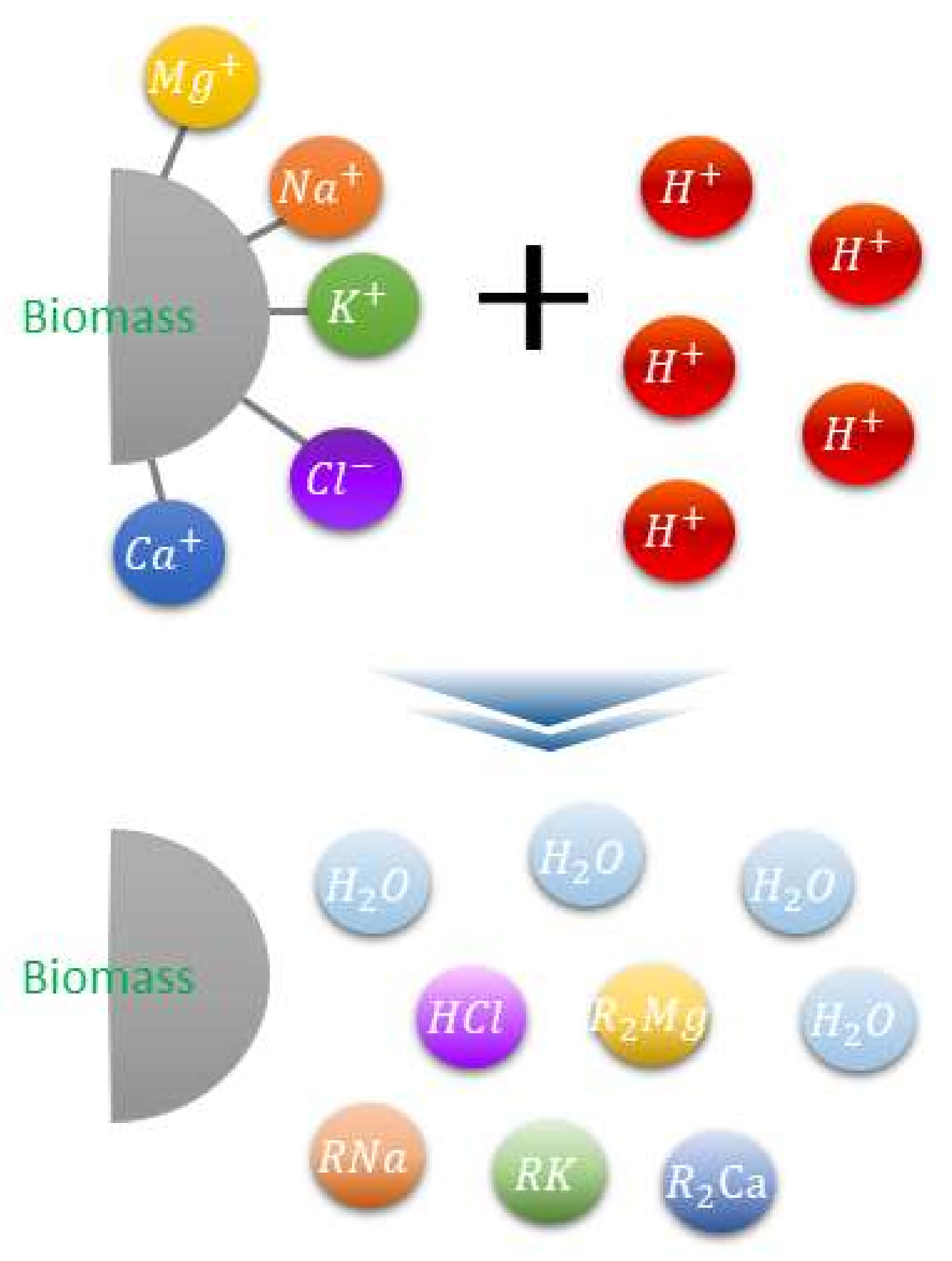
In the present study, a lab-scale reactor for extracting ash from biomass was designed and manufactured through consultation with the Korea Institute of Energy Research. Experiments were conducted using a procedure previously reported [9]. The batch ash removal reactor is composed of the reactor, hot water supply tank, and control system. As shown in the reference [9], the reactor contains the raw biomass with a motor that rotates at 100 rpm. The hot water supply tanks contain acid water (citric acid). Meanwhile, the temperature of the supply tank, as well as the rotation rate, can be manipulated by the control system.
Although the reactor capacity is approximately 20 L, approximately 2 kg of biomass and 16 kg of a citric acid solution (pH 2–7) were mixed per batch due to the low density of the biomass. A hydrothermal supply was connected through the side of the reactor, and the reaction temperature (60–120 °C) was controlled by adding steam into the reactor jacket. The mixture in the reactor was stirred at 300 rpm to maximize interactions between the biomass and the acid solution. Ash extraction was achieved as per the protocol presented in Figure 2. The duration of the experiment was fixed at 10 min to evaluate the potential of rapid ash extraction. After each experiment, the sample mixture was recovered through discharge at the bottom of the reactor, and the solid and liquid components were separated using a 1 µm filter paper. The separated solids were washed five times using pure water and subsequently dried in an oven for subsequent use as ALB in a power plant boiler. Proximate and ultimate analyses were performed to determine the calorific value and ash properties, which were used to evaluate ash extraction effects.
Thermal coal was then blended with 5% and 10% of the three biomass types, which were representative of underexploited biomass, including TW and kenaf, as well as reference biomass, WP, which is mainly used in power plants in Vietnam. Proximate analysis was conducted using a TGA-701 thermogravimeter (LECO Co., St. Joseph, MI, USA), while ultimate analysis was performed using a TruSpecific analyzer and an SC-432DR sulfur analyzer (LECO). The calorific value of each sample was measured using a Parr 6320EF calorimeter, while ash properties were determined by X-ray fluorescence (XRF) using a Primus II instrument (RIGAKU Co. Akishima, Tokyo, Japan). Analyses were performed according to ASTM standards [10,11,12,13,14,15], and results from the proximate, ultimate, and calorific value analyses are presented in Table 1.

2.2. Ash Removal

Ash properties were characterized by XRF using a Primus II (RIGAKU Co.) instrument according to ASTM standards [15]. The concentrations of chlorine, an element associated with reduction of the ash melting point and promotion of slagging and fouling, were measured by ion chromatography. Ion chromatography involves an ion exchange principle in which a functional group associated with a cation or anion is bonded to a polymer representing the stationary phase of the column. If an unknown substance is injected, the ions of the sample initiate cation or anion substitution and recurrent bond decomposition [16].
The composition of ash from the biomass before and after fuel conversion treatment is presented in Table 2. Evidently, ALB treatment impacted the potential for slagging and fouling. Changes in the concentrations of K and Na were evaluated using Equations (1)–(4):
A c t u a l         c o n t e n t   p p m = A s h w t % × K + w t % × 100
A c t u a l   N a +   c o n t e n t   p p m = A s h w t % × N a + w t % × 100
K +   r e m o v a l   e f f i c i e n c y = 100 A s h A w t % × K + A w t % A s h r a w w t % × K + r a w w t % × 100
N a +   r e m o v a l   e f f i c i e n c y = 100 A s h A w t % × N a + A w t % A s h r a w w t % × N a + r a w w t % × 100
where AshA is the ashless biomass ash component, Ashraw is the raw biomass ash component, KA is the ashless biomass K+ content, Kraw is the raw biomass K+ content, and Na is associated with the same parameters.

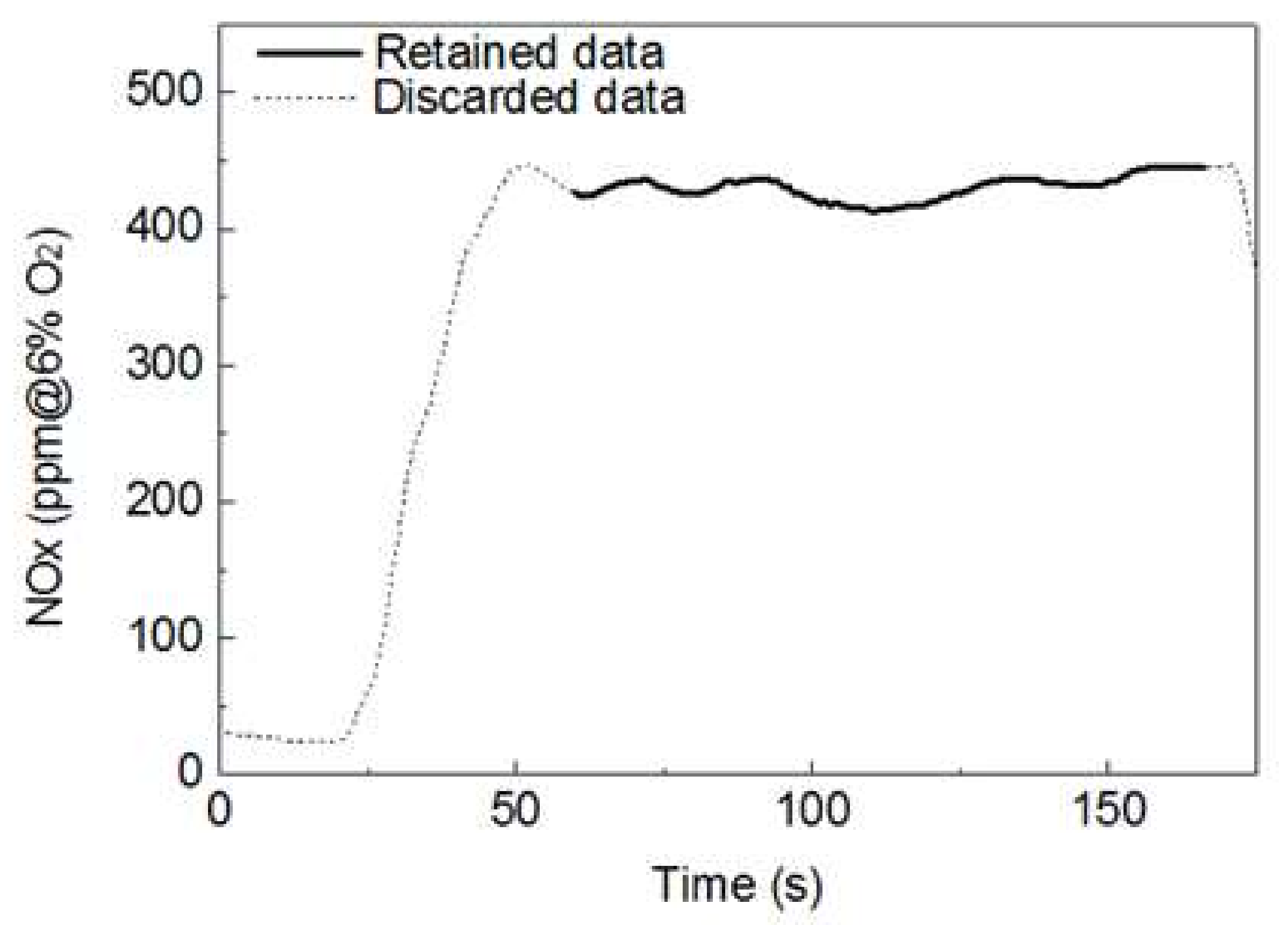
2.3. Gas Emission and Unburned Carbon Analysis

Gases produced using the drop tube furnace (DTF), which reflect the actual boiler, such as NOx and SOx, as well as the unburned carbon (UBC), were determined. Experiments were performed in triplicate. Components in the exhaust gas at the rear end of the DTF were analyzed every second, and the data were stored in a laptop wirelessly connected to the analyzer. The average data of the exhaust gas components for each sample type were associated with a semi-normal state of the combustion reaction shown in Figure 3. The results obtained vary based on the experimental conditions; in particular, the NOx concentration significantly changed depending on the CO2 and O2 in the exhaust gas. In general, the NOx concentration can be obtained based on a reference O2 concentration of 6%. The conversion can be performed using Equation (5):
N O x ,   @   6 %   O 2 = 21 % O 2 , m e a s u r m e n t % 21 % 6 % × N O x ,   m e a s u r e m e n t
Regarding the UBC, owing to the low collectible char or ash relative to the initial fuel utilized, this component was determined using the ash tracer method. This method enables the comparison of the ash content associated with char after combustion to that of the fuel before combustion. The burnout or UBC of the fuel is then determined based on a proportionality relationship as expressed in Equation (6) [17]:
U B C % = A 0 100 A c h a r ( A c h a r 1 A 0 × 100
where A0 is the ash content of the pre-combustion sample and Achar is the ash content of the char after combustion.

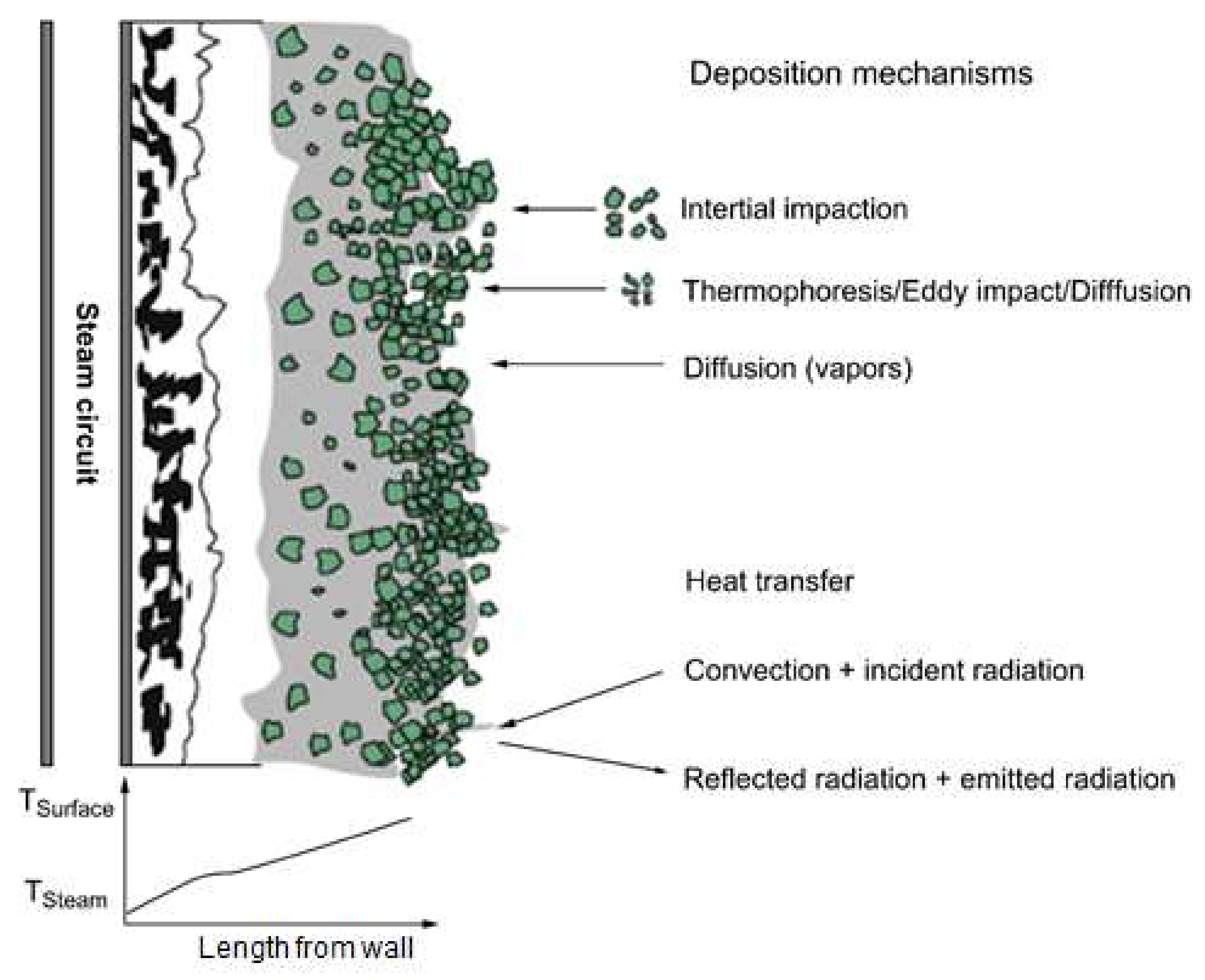
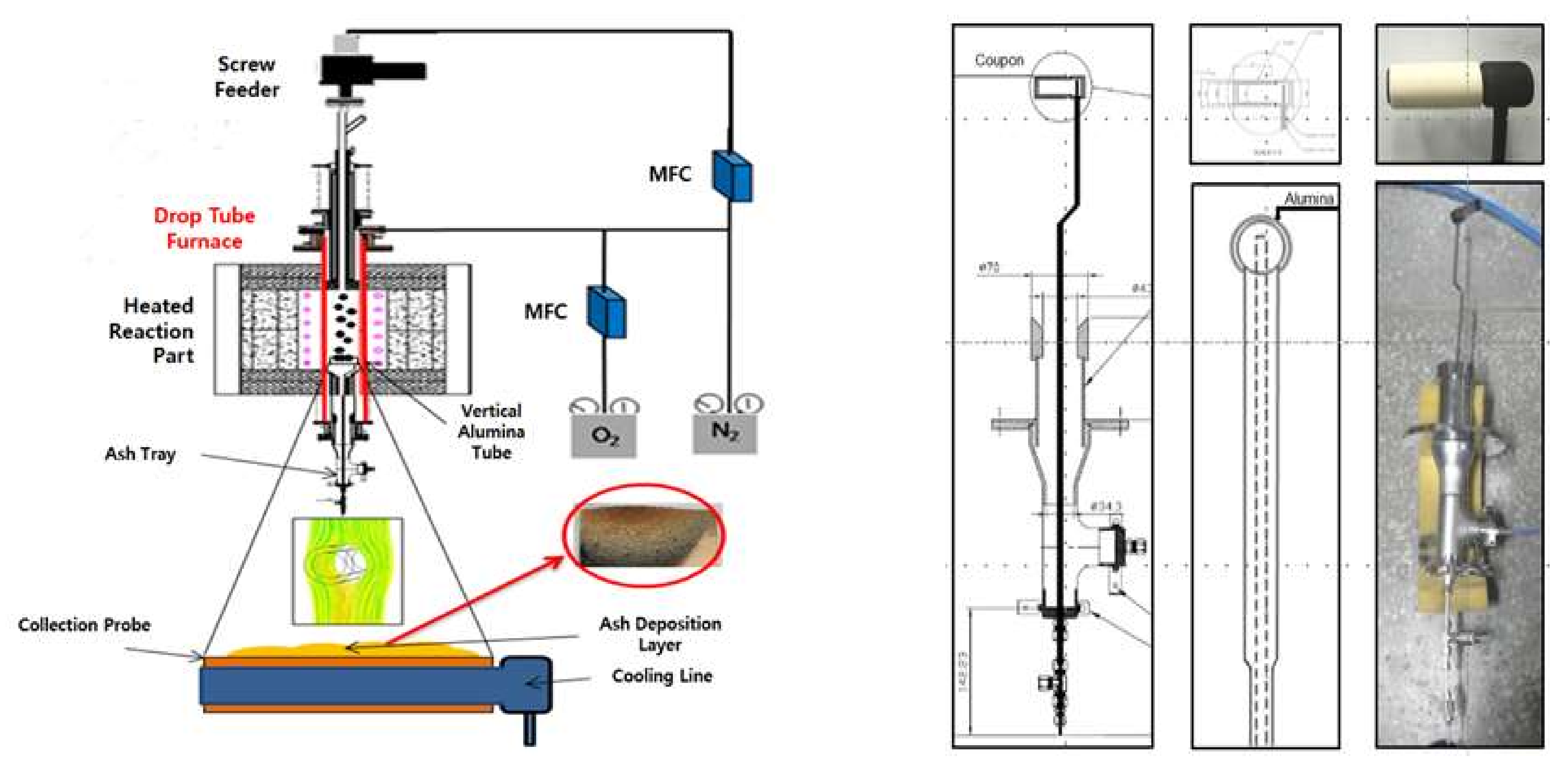
2.4. Ash Deposition Rate Experiment

To adequately understand slagging and fouling, which are phenomena commonly associated with ash deposition, elucidation of the ash deposition mechanism is necessary. A proposed mechanism for ash generation during coal combustion is displayed in Figure 4. Exposure of coal to the high-temperature boiler environment is accompanied by the volatilization of some components, while others produce fine particles, and the rest remain as char particles. If the temperature drops, certain volatilized inorganic materials revert to fine particles through nucleation, followed by fusion to regenerate ash. Meanwhile, a portion of the inorganic particles in the char are liberated through char combustion. Although the ash is a component of a particle, as described in Figure 4, its generation is associated with varying pathways. Consequently, ash samples are characterized by diverse particle size distributions after combustion. This generation path is essentially controlled by the environment the coal is exposed to during the carbonization process, the carbonization duration, and the source material of the coal. In addition, the generation pathway can be influenced by the temperature and associated parameters of the combustion system. Consequently, most studies on slagging and fouling have focused on the mineral properties of coal, particularly the composition, distribution, and size of ash components, as well as their structural properties. Existing slagging and fouling models are based on empirical relationships derived from experimentally measured physicochemical phenomena. Therefore, all variables are associated with the ash component as an input. Thus, the prediction of slagging and fouling must involve a precise and quantitative analysis of the coal, including the identification and classification of inorganic minerals as well as their properties, such as the size, density, and melting point. Slagging and fouling in a boiler often commence with deposition. The melting and formation of sintered layers by deposited particles is termed slagging, whereas condensation of particle batches on a relatively low-temperature surface to produce layers is known as fouling. Therefore, these phenomena are distinct or coexist depending on the temperature and related conditions. The mechanism of deposition on the walls of a combustion furnace is illustrated in Figure 4. Deposition on a clean surface begins with the collision of particles circulating in the reactor, and large particles are deposited by inertial impact, while small particles are added on the inner walls at lower temperatures through thermophoresis, eddy impact, and diffusion. In addition, some inorganic ions associated with gases also condense and are deposited on the inner walls of the furnace. Deposition may also arise from reactions between solids and gases [18,19], and the ash deposition rate can be expressed as shown in Equation (7) [20]:
d m d t = I · C E + E + T + C + R
where I is the inertial impaction rate, CE represents the capture efficiency, E denotes the eddy impaction, T designates the thermophoretic deposition rate, C refers to the condensation rate, and R is the reaction rate.
These parameters are further described as follows: during the inertial impact (I), particles are characterized by sufficient momentum to pass through the surrounding fluid flow region and collide with obstacles such as tubes. This represents the dominant mechanism for the rapid accumulation of ash in superheater tubes. The capture efficiency (CE) is the extent to which particles remain on a surface after the collision through inertial impact. The eddy impaction (E) is a phenomenon during which fine ash particles are deposited on the surfaces of particles as a function of turbulence. This involves particles unaffected by inertial impaction, and commonly involves other mechanisms. Thermophoresis (T) refers to the movement of particles associated with rapid temperature gradients. This generally affects fine particles associated with a low-temperature range transport. Batch precipitation in cooled superheater tubes is a prime example of ash precipitation associated with this mechanism. Inertial impact usually occurs only on the upstream side of the tube, whereas batch precipitation caused by thermophoresis is uniformly present throughout the tube. During condensation (C), vaporized inorganic particles (mainly alkalides) are formed by agglomeration on a low-temperature surface. The relatively low temperature around a cooled tube promotes the condensation of some gas components, which causes precipitation on the tube. The generation is controlled by the gas components and the temperature. Reactions (R) between solids and gases directly affect the ash deposition rate and the characteristics of the ash. Principal reactions associated with ash deposition include sulfation, alkali absorption, and oxidation. These reactions are governed by the concentration gradients of species present.
Owing to its close association with the deposition rate, the CE is the focus of the present study. Experiments were conducted using a DTF, which is suitable for simulating a solid fuel boiler, and its components are displayed in Figure 5. Many studies on coal combustion have been conducted using the DTF as it can be operated at different temperatures and pressures. The DTF comprises an injection unit through which samples and gases are introduced, a reaction unit for combustion, and a collection unit for the collection of samples and analysis of emissions. The fuel and reaction gases are introduced through the injection unit, and these gases include a carrier gas associated with the fuel, as well as a the main reaction gas injected near the tube transporting the carrier gas. The fuel and reaction gas quantities can be adjusted using a feeder system, which includes a syringe pump, a flow rate controller, and a flow meter. The reaction unit is where the interactions between the fuel and reactive gas occur. A constant temperature field was generated in the reaction unit by adjusting the temperature of the SiC heater using a temperature controller; the temperature can reach 1300 °C in the DTF. The collection unit enables the recovery of the sample after the experiment. To prevent further oxidation reactions in the char, cool water is passed through the collection probe to lower its temperature. The gases and solids can then be separated using the lower cyclone. In addition, by changing the probe of the collecting unit, the ash deposition can be measured, which was the focus of the current study.
The ash deposition experiment was performed using the DTF equipped with a probe for ash deposition (Figure 5). The probe contained a hollow cylinder and was maintained at a low temperature using circulating water, to prevent the melting associated with the high temperature used in the experiment. The hollow cylinder was designed to adequately separate the ash after deposition so that the deposited ash could be collected. The experimental conditions included a furnace temperature of 1300 °C and a sample feeding rate of 0.16 g/min to attain 10 g. These conditions impact the ash deposition, especially the gas temperature, which is favorable for slagging in the radiative zone, and this is consistent with previous studies [21]. The probe was tested approximately 5 cm from the bottom in the reaction zone, representing a position at which particles are characterized by low carbon contents due to the impact of combustion and ambient temperature. The internal combustion conditions were approximately 1.16 times higher relative to the excess air volume, which was similar to conditions in a boiler. Based on the feeding rate of 0.16 g/min, approximately 1 h was required to introduce 10 g of each sample.
Ash deposition was evaluated based on the masses obtained after the DTF experiments. These measurements were normalized to accommodate differences associated with the samples, and were compared using the following indexes:
The CE [22] was calculated by dividing the mass of adhered particles by the mass of particles that passed through the projected surface area of the probe (Equation (8)). Thus, the CE indicates the fraction of the deposited ash and highlights the tendency of particles to adhere without considering the ash generation potential of a sample.
C E = m D e p m a s h A c o u p o n A r e a c t o r × 100   % k g D e p / k g A s h
Alternatively, this can be expressed using measured parameters as in Equation (9)
C E = m D e p m F u e l A P 100 A c o u p o n A r e a c t o r × 100   % k g D e p / k g A s h
where mDep, mAsh, and mFuel represent the mass of ash deposited, the mass of ash passing through the reaction unit, and the mass of sample utilized in the experiment, respectively. Acoupon is the projected area of the hollow cylinder, and Areactor is the cross-sectional area of the DTF, while AP is the amount of raw ash in the sample. Therefore, the CE is useful for determining the fraction of particles associated with adhesion. However, this index neglects other effects associated with the boiler. First, the mineral matter quantity significantly affects the ash growth rate during deposition. Second, the coal quantity utilized to produce the desired energy depends on its calorific value. These effects are encompassed in the energy based growth rate (GRE), which is defined as the growth rate of ash deposition per calorie during coal combustion and can be expressed with Equation (10) [23].
m D e p L H V · m F e u l     g D e p / M J   o r g D e p / s / M W
Based on Equation (10), the CE and GRE can be related through Equation (11).
G R E = C E · 10 3 100 × A P 100 × 1 L H V × A c o u p o n A r e a c t o r   g D e p / M
Better prediction of slagging can be achieved by using an index related to the material based on energy rather than the ash properties. This suggests that the GRE can serve as an important practical index. Nevertheless, the CE provides information on specific aspects of the deposition.

3. Results and Discussion

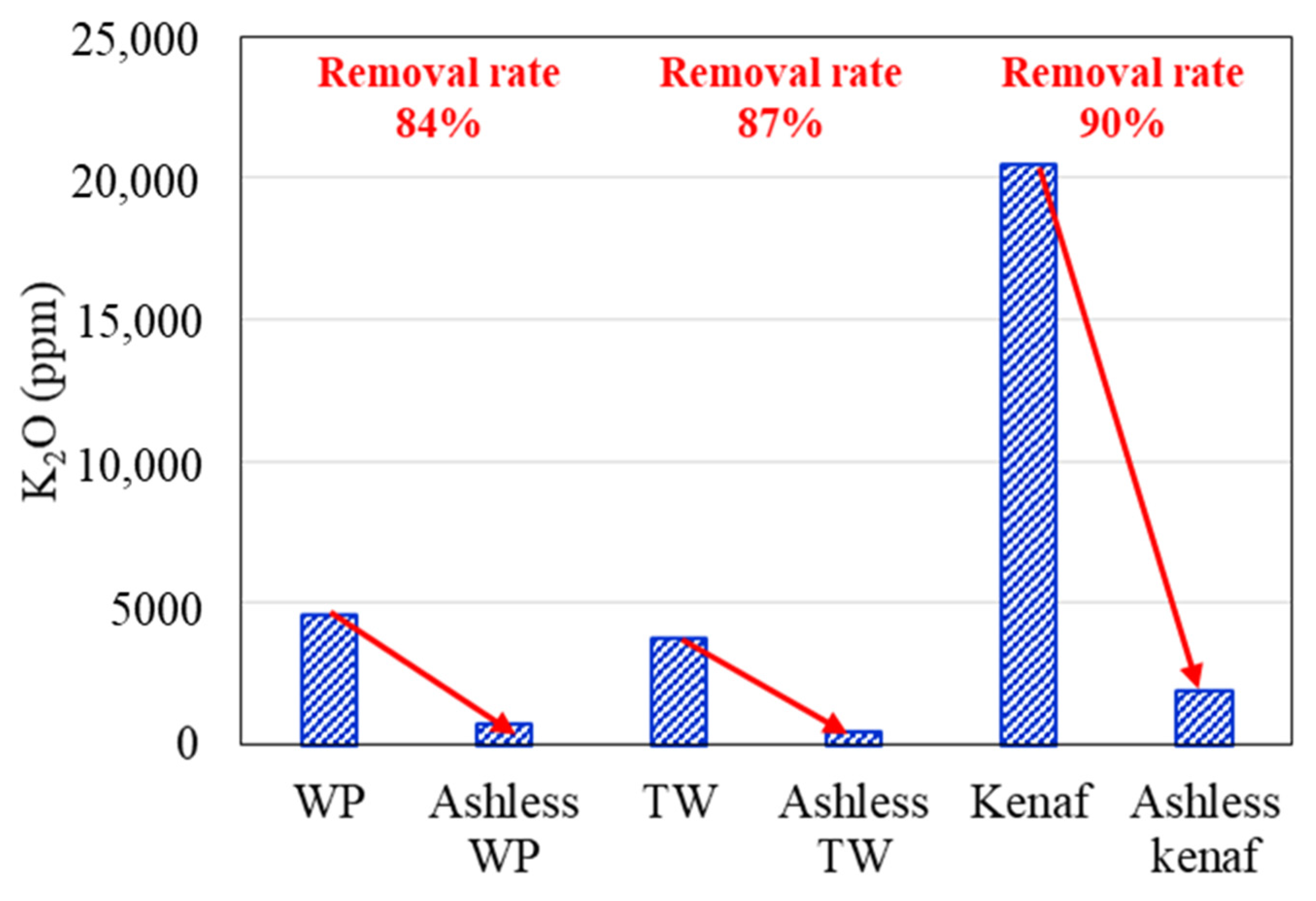
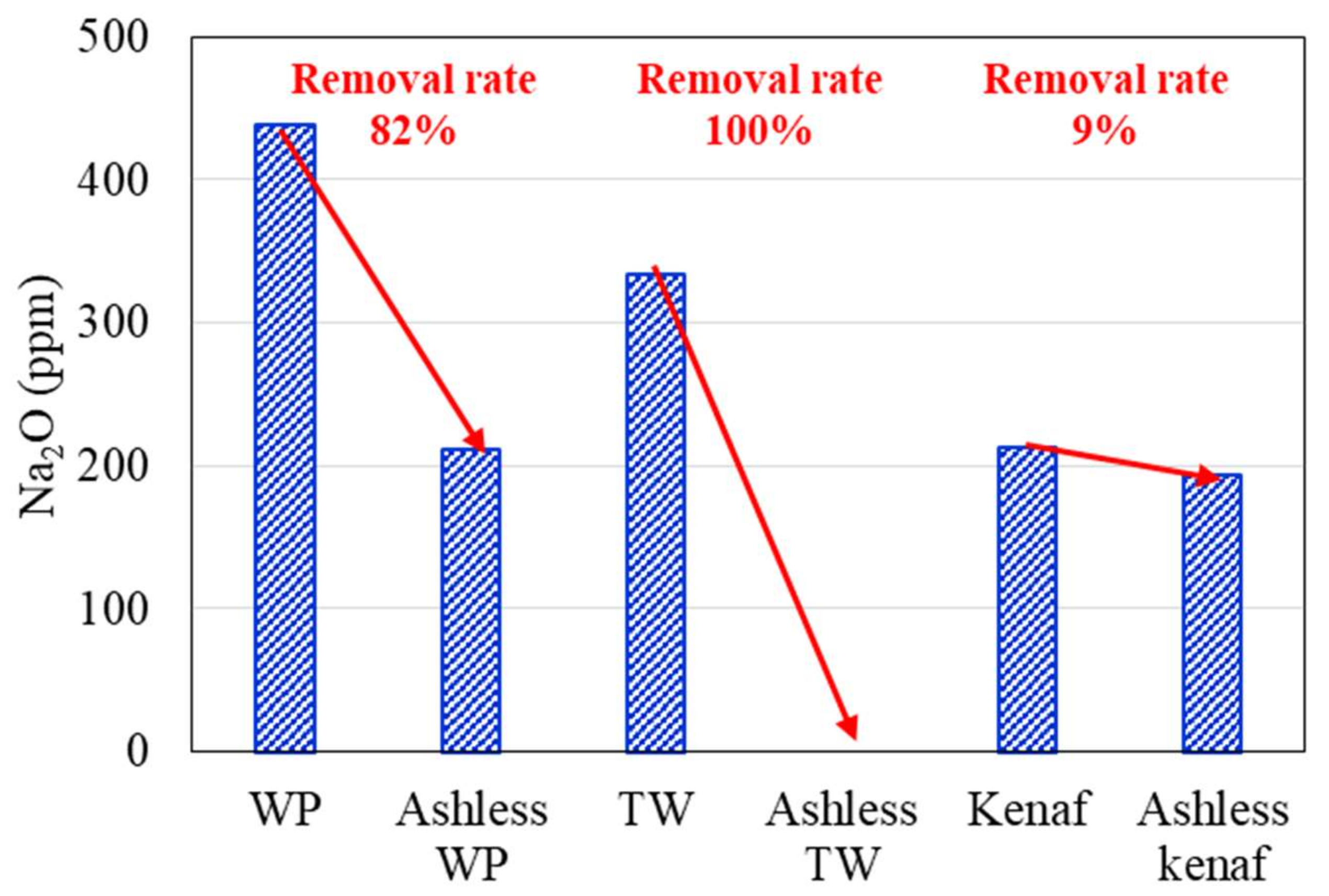
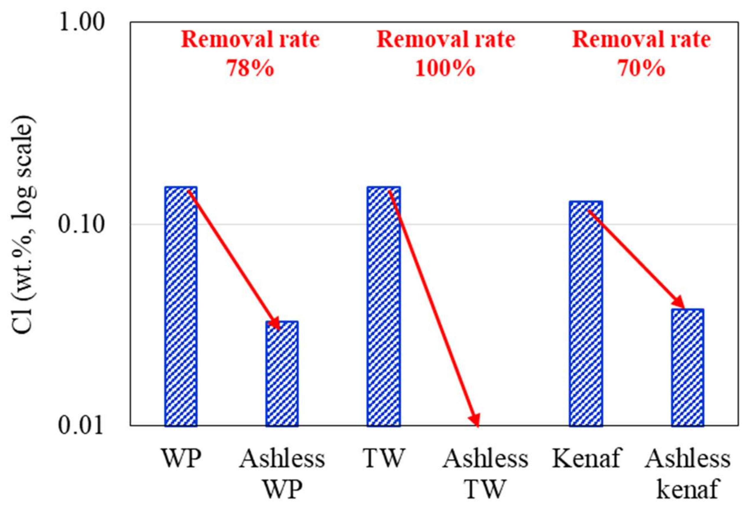
3.1. Ash Removal Associated with the Pretreatment

Changes in the K2O, Na2O, and Cl concentrations of the biomass types associated with the ALB treatment are presented in Figure 6, Figure 7, Figure 8, respectively. The WP, which was introduced for comparison, displays removal efficiencies of 84%, 78%, and 82% for K, Na, and Cl, respectively, after ALB treatment. The unexploited TW shows removal efficiencies of 87%, 100%, and 9% for K, Na, and Cl, respectively. Relatedly, kenaf was associated with K, Na, and Cl removal efficiencies of 90%, 9%, and 70%, respectively. In kenaf, K was preferentially extracted relative to Na due to its higher reactivity.

3.2. Gases and UBC Associated with the ALB Co-Combustion

Experiments were conducted using coal and coal mixtures containing 5% and 10% raw and ALB biomass. The generated gas composition and UBC data are presented in Table 3. Overall, after mixing coal and biomass, the NOx and UBC tended to decrease, while the SOx slightly increased. However, in most cases, the SOx values of approximately 30–50 ppm are relatively lower than those produced from bituminous and sub-bituminous coals [24,25]. In all cases, the NOx and SOx values converge toward an error of approximately 10 ppm, whereas the UBC data shows no trend. These characteristics are attributed to the removal of alkali metal ions through the ALB treatment, without any influence of the combustion [26].

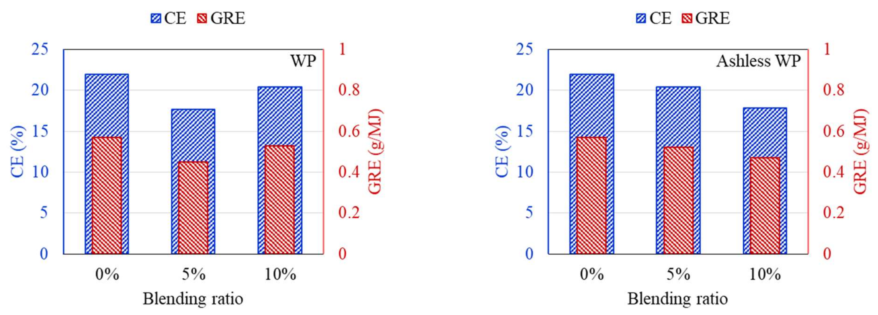
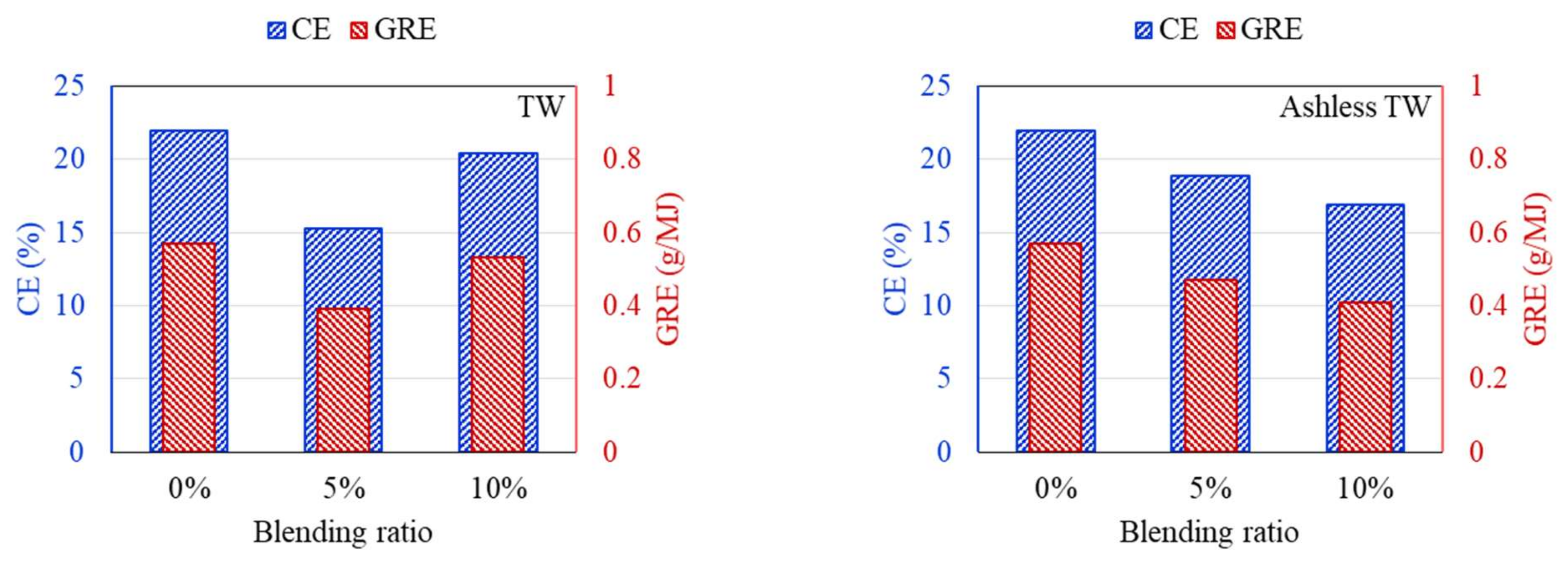
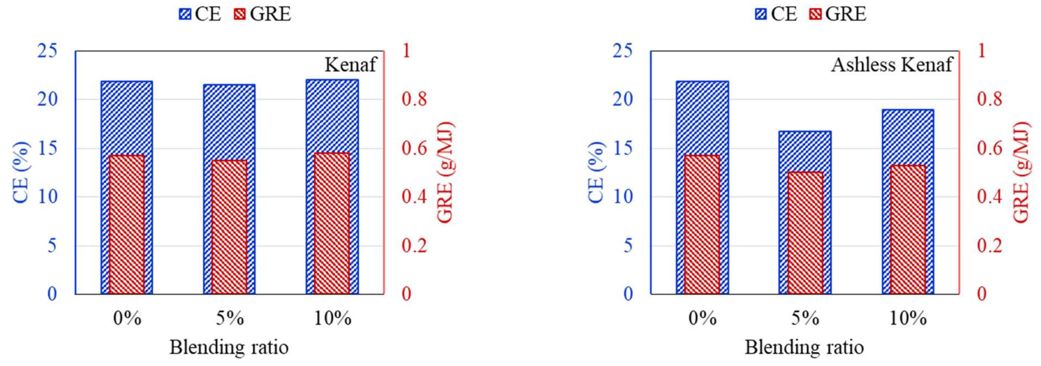
3.3. Ash Deposition Rate after the ALB Cofiring

DTF experiments were conducted to compare the ash deposition produced by coal mixed with raw and ashless biomass. In general, the ash component of coal is divided into indexes to suppress clinker generation, and the effect on clinker development is predicted and evaluated based on short or mixed coal. First, the properties of the raw materials were analyzed to predict the clinker development for each sample. Deposition characteristics of samples containing 5% and 10% of each biomass type were compared using the DTF experiment data. The feeding amount and deposited mass of ash are shown in Table 4. Also, CE and GRE were calculated to evaluate the ash deposition of various fuels, and the results are displayed in Figure 9, Figure 10, Figure 11. The CE involves the deposition associated with the ash in coal before combustion, while the GRE reflects the ash linked to the energy supplied.
According to the DTF deposition experiments, the ash, CE, and GRE for the six coal–biomass mixtures tended to decrease. However, the ash deposition associated with the TW increased from 0.09 g when mixed with 5% to 0.125 g when mixed with 10%, while the CE correspondingly increased from 15.24% to 20.42%. Conversely, the ash deposition for the ashless TW decreased from 0.11 g for the 5% mixture to 0.099 g for the 10% mixture, and these changes were confirmed by the CE, while the adhesion ratio decreased to 16.87%. Regarding the ashless kenaf, the deposited ash increased from 0.098 g for 5% to 0.116 g for 10% mixing, which is comparable to the 0.128 g produced by mixing with 5% of the raw kenaf. However, a comparison of the ash deposition associated with the raw coal and the mixtures revealed the largest decrease in the ash, CE, and GRE, indicating that the coal impacted the ash deposition potential of each sample. Collectively, these findings indicate that for the raw biomass, as the proportion of mixing increased, more ash was deposited, and the CE and GRE increased. However, for the ashless biomass, the ash deposition, CE, and GRE decreased as the proportion of mixing increased. Therefore, mixing with ashless biomass seems to decrease the ash deposited by samples. The ashless biomass quantity, however, decreased as the ashless biomass proportion in the mixture increased. This is beneficial in relation to clinker generation, which occurs due to mixing in coal boilers, and causes numerous issues.

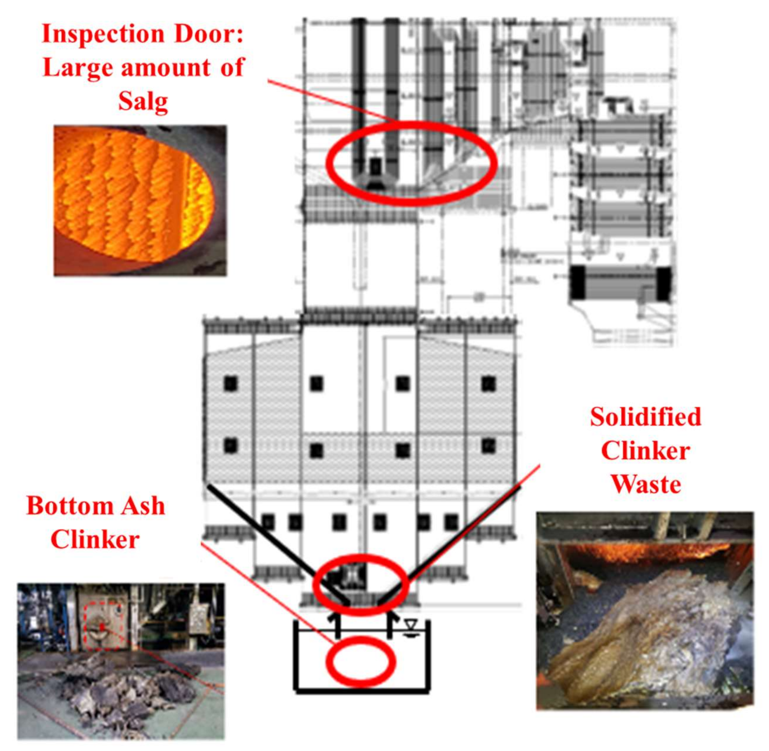
3.4. Effect of Ash Removal Pretreatment on the Boiler

According to the results shown in Figure 7, Figure 8, Figure 9, all biomass samples without pretreatment exhibit a V-shaped variation. This pattern is consistent with that reported for the CE and GRE in a previous study [21]. Moreover, studies have also revealed that this trend does not apply to samples with low ash content [27]. However, if biomass associated with high ash is utilized, a similar trend is observed [28]. Therefore, the CE and GRE data generated in the present study confirmed the benefit of the ash removal treatment on ash deposition. Regarding the raw biomass associated with high ash, further co-combustion after generation of the V-shaped pattern can elevate the ash in the boiler due to an increase in alkali metals in the sample. Conversely, for the ALB, which involves ash removal, the total alkali decreases. Therefore, the ALB technique exhibits the potential for minimizing slagging and fouling in a boiler. Further, combustion involving just ALB samples will likely significantly reduce the operating costs.

4. Conclusions and Summary

In this study, the slagging and fouling associated with underexploited biomass (TW and kenaf) before and after ash removal pretreatment was investigated. Ash removal pretreatment involved the neutralization of metal ions and carboxylic acids contained in the biomass ash. The primary findings of the study can be summarized as follows:
(1)
XRF and ion chromatography revealed that ash removal pretreatment decreased the ash content produced by the three types of biomass, and the abundance of Na, Mg, K, and Cl, which are associated with clinker generation, decreased by > 80%.
(2)
DTF and gas analysis revealed that after mixing with 5% and 10% biomass, the NOx and UBC decreased, while SOx slightly increased. However, in most cases, the SOx values ranged between 30–50 ppm, which are lower than those for bituminous and sub-bituminous coal. Moreover, the NOx and SOx values for all samples decreased slightly, however, converged toward an error of approximately 10 ppm, while the UBC showed no trend.
(3)
Ash deposition in the DTF, CE, and GRE was analyzed. Raw biomass exhibited a V-shaped variation due to the presence of alkali contents in raw biomass. With ash removal pretreatment, these effects disappeared as CE and GRE gradually decreased.
In conclusion, ash removal pretreatment can be adopted to minimize slagging and fouling in a boiler, which will effectively eliminate internal corrosion and reduce the boiler operation cost. Additionally, the generation of fine particulate matter, representing another environmental issue, may also be decreased by the ALB technique.

Author Contributions

The manuscript was written through contributions of D.-G.L. as a first author; D.-G.L., M.-J.K., K.-H.K. and J.-S.K. designed and conducted the experiment; D.-G.L. and S.-M.K. analyzed the data; D.-G.L. performed validation writing; C.-H.J. is the corresponding author of this paper. All authors have read and agreed to the published version of the manuscript.

Funding

This research received no external funding.

Institutional Review Board Statement

Not applicable.

Informed Consent Statement

Not applicable.

Acknowledgments

This research was conducted under framework of the research and development program of The Korea Institute of Energy Research (C1-2428-01).

Conflicts of Interest

The authors declare no conflict of interest.

Abbreviations

ALBAshless biomass, biomass from the ash removal process
DTFDrop Tube Furnace
WPWood Pellet
TWThinned Wood
UBCUnburned Carbon
CECapture Efficiency
GREEnergy Based Growth Rate

References

  1. WPAC Drax Biomass. 2016. Available online: https://www.pellet.org/wpac-agm/images/2016/Drax-Biomass---WPAC-2016---For-Sharing.pdf (accessed on 5 June 2020).
  2. Data Basis Made with Natural Earth, AMI/LK/MIO. 2017. Available online: https://www.ufop.de/ (accessed on 20 June 2019).
  3. Islam, A.S.; Ahiduzzaman, M. Green electricity from rice husk. In A model for Bangladesh, Thermal Power Plants-Advanced Applications; Rasul, M., Ed.; IntechOpen: London, UK, 2013; pp. 127–144. [Google Scholar]
  4. Qian, X.; Lee, S.; Chandrasekaran, R.; Yang, Y.; Caballes, M.; Alamu, O.; Chen, G. Electricity evaluation and emission characteristics of poultry litter co-combustion process. Appl. Sci. 2019, 9, 4116. [Google Scholar] [CrossRef] [Green Version]
  5. Papilo, P.; Kusumanto, I.; Kunaifi, K. Assessment of agricultural biomass potential to electricity generation in Riau Province. IOP Conf. Ser. Earth Environ. Sci. 2017, 65, 012006. [Google Scholar] [CrossRef] [Green Version]
  6. Bryers, R.W. USA Fireside Slagging, Fouling, and High-Temperature Corrosion of Heat-Transfer Surface Due to Impurities in Steam-Raising Fuels. Prog. Energy Combust. Sci. 1996, 22, 29–120. [Google Scholar] [CrossRef]
  7. Qian, X.; Xue, J.; Yang, Y.; Lee, S.W. Thermal properties and combustion-related problems prediction of agricultural crop residues. Energies 2021, 14, 4619. [Google Scholar] [CrossRef]
  8. Niu, Y.; Tan, H. Ash-related issues during biomass combustion: Alkali-induced slagging, silicate melt-induced slagging (ash fusion), agglomeration, corrosion, ash utilization, and related countermeasures. Prog. Energy Combust. Sci. 2016, 52, 1–61. [Google Scholar] [CrossRef]
  9. Lee, Y.; Park, J.; Song, G.; Namkung, H.; Park, S.; Kim, J.; Choi, J.; Jeon, C.; Choi, Y. Characterization of PM2.5 and Gaseous emissions during combustion of ultra-clean biomass via dual-stage treatment. Atmos. Environ. 2018, 193, 168–176. [Google Scholar] [CrossRef]
  10. ASTM D3173/D3173M-17a. Standard Test Method for Moisture in the Analysis Sample of Coal and Coke; ASTM International: West Conshohocken, PA, USA, 2017. [Google Scholar]
  11. ASTM D3175-20. Standard Test Method for Volatile Matter in the Analysis Sample of Coal and Coke; ASTM International: West Conshohocken, PA, USA, 2020. [Google Scholar]
  12. ASTM D3172-13. Standard Test Method for Fixed Carbon in the Analysis Sample of Coal and Coke; ASTM International: West Conshohocken, PA, USA, 2017. [Google Scholar]
  13. ASTM D3174-12(2018)e1. Standard Test Method for Ash in the Analysis Sample of Coal and Coke from Coal; ASTM International: West Conshohocken, PA, USA, 2018. [Google Scholar]
  14. ASTM D5373-16. Standard Test Methods for Determination of Carbon, Hydrogen and Nitrogen in Analysis Samples of Coal and Carbon in Analysis Samples of Coal and Coke; ASTM International: West Conshohocken, PA, USA, 2016. [Google Scholar]
  15. ASTM D5865-13. Standard Test Method for Gross Calorific Value of Coal and Coke; ASTM International: West Conshohocken, PA, USA, 2013. [Google Scholar]
  16. Peng, B.; Wu, D.; Lai, J.; Xiao, H.; Li, P. Simultaneous determination of halogens (F, Cl, Br, and I) in coal using pyrohydrolysis combined with ion chromatography. Fuel 2012, 94, 629–631. [Google Scholar] [CrossRef]
  17. Ballantyne, T.R.; Ashman, P.J.; Mullinger, P.J. A new method for determining the conversion of low-ash coals using synthetic ash as a tracer. Fuel 2005, 84, 1980–1985. [Google Scholar] [CrossRef]
  18. Lourival, J.; Mendes, N.; Bazzo, E. Characterization and growth modeling of ash deposits in coal fired boilers. Powder Technol. 2012, 217, 61–68. [Google Scholar]
  19. Standards Association of Australia Coal and Coke Analysis and Testing, Part 15: Higher Rank Coal Ash and Coke Ash Fusibility, 3rd ed.; Standards Australia: Homebush, NSW, Australia, 1995.
  20. Rushdi, A.; Sharma, A.; Gupta, R. An experimental study of the effect of coal blending on ash deposition. Fuel 2004, 83, 495–506. [Google Scholar] [CrossRef]
  21. Jeong, T.; Sh, L.; Kim, J.; Lee, B.; Jeon, C. Experimental investigation of ash deposit behavior during co-combustion of bituminous coal with wood pellets and empty fruit bunches. Energies 2019, 12, 2087. [Google Scholar] [CrossRef] [Green Version]
  22. An, K.J.; Lee, B.H.; Kim, S.I.; Jeon, C.H. Study on slagging characteristic of hybrid coals using the thermo-mechanical analysis. In Proceedings of the Yeongheung Spring Conference on K.S.M.E., Yoengheung, Korea, 31 May 2013. [Google Scholar]
  23. Blanchard, R. Measurements and Modeling of Coal Ash Deposition in an Entrained Flow Reactor. Master’s Thesis, Brigham Young University, Provo, UT, USA, 2008. [Google Scholar]
  24. Pudasainee, D.; Kim, J.H.; Lee, S.-H.; Park, J.-M.; Jang, H.-N.; Song, G.-J.; Seo, Y.-C. Hazardous air pollutants emission from coal and oil-fired power plants. Asia Pac. J. Chem. Eng. 2010, 5, 299–303. [Google Scholar] [CrossRef]
  25. Li, S.; Xu, T.; Sun, P.; Zhou, Q.; Tan, H.; Hui, S. NOx and SOx emissions of a high sulfur self-retention coal during air-staged combustion. Fuel 2008, 87, 723–731. [Google Scholar] [CrossRef]
  26. Jiang, Y.; Jeon, C. Comparative study on combustion and emission characteristics of torrefied and ashless biomass with coal through the 500 MW tangentially fired boiler simulation. Energy Fuels 2021, 35, 561–574. [Google Scholar] [CrossRef]
  27. Abreu, P.; Casaca, C.; Costa, M. Ash deposition during the co-firing of bituminous coal with pine sawdust and olive stones in a laboratory furnace. Fuel 2010, 89, 4040–4048. [Google Scholar] [CrossRef]
  28. Kupka, T.; Mancini, M.; Irmer, M.; Weber, R. Investigation of ash deposit formation during co-firing of coal with sewage sludge, saw-dust and refuse derived fuel. Fuel 2008, 87, 2824–2837. [Google Scholar] [CrossRef]
Figure 1. Illustration of clinker and high-temperature corrosion issues associated with biomass fuel.
Energies 14 07391 g001
Figure 2. Biomass ash elimination mechanism involving acid treatment [9].
Energies 14 07391 g002
Figure 3. Plot showing an example of the processing of data used for analysis of the exhaust gas.
Energies 14 07391 g003
Figure 4. Conceptual illustration of mechanisms of ash deposition on the walls of a furnace [18].
Energies 14 07391 g004
Figure 5. Schematic representation of the components of a drop tube furnace (DTF) connected to an ash deposition probe [21].
Energies 14 07391 g005
Figure 6. K2O contents of three biomass types before and after the ALB treatment.
Energies 14 07391 g006
Figure 7. Na2O contents of three biomass types before and after the ALB treatment.
Energies 14 07391 g007
Figure 8. Cl contents of the biomass types before and after ALB treatment.
Energies 14 07391 g008
Figure 9. CE and GRE for cofiring different blends of the WP (left) and ashless WP (right).
Energies 14 07391 g009
Figure 10. CE and GRE for cofiring different blends of the TW (left) and ashless TW (right).
Energies 14 07391 g010
Figure 11. CE and GRE of cofiring different blends of the kenaf (left) and ashless kenaf (right).
Energies 14 07391 g011
Table 1. Basic properties (proximate, ultimate value and heating value) of coal and biomass samples.
SampleCoal AWPAshless WPTWAshless TWKenafAshless Kenaf
Proximate analysis (ad)
Inherent moisture (wt.%)3.316.605.823.283.303.383.08
Ash (wt.%)15.303.461.554.521.576.081.94
Volatile matter (wt.%)33.1769.9074.4671.6974.1772.1976.65
Fixed carbon (wt.%)48.2320.0418.1820.5220.9618.3718.33
Ultimate analysis (DAF)
C (wt.%)84.6343.0349.3048.6848.9543.5547.30
H (wt.%)5.375.385.696.186.075.786.29
O (wt.%)7.4850.5444.7044.4146.9048.3150.11
N (wt.%)1.762.880.302.592.522.862.86
S (wt.%)0.760.700.010.000.000.050.00
LHV (kcal/kg)5593417738644566455441294411
ad: air dry, DAF: dry ash free, LHV: low heating value.
Table 2. Ash composition rate of coal and raw biomass om ALB samples.
Sample (wt.%)SiO2Al2O3Fe2O3CaOMgONa2OK2OOthersCl
Coal A65.4523.974.871.070.70.271.242.44N.D
WP24.623.873.0424.925.521.2713.2523.520.13
Ashless WP32.694.973.8627.752.721.364.8521.80.04
TW46.5510.603.6619.483.450.748.367.160.03
Ashless TW72.569.370.7011.230.000.003.063.080.01
Kenaf6.712.080.8213.758.940.3533.6733.683.85
Ashless kenaf20.714.794.7523.976.371.009.7329.060.03
N.D: not detected.
Table 3. Summary of the gas and UBC concentration in different sample blends.
SampleNOx (ppm)SOx (ppm)UBC (%)
Coal A102.8527.7240.43
Coal A + WP (5%)87.1440.5128.18
Coal A + WP (10%)95.6438.2737.53
Coal A + Ashless WP (5%)96.3439.3220.04
Coal A + Ashless WP (10%)93.7342.2515.45
Coal A + TW (5%)84.1530.6427.92
Coal A + TW (10%)84.8935.7427.24
Coal A + Ashless TW (5%)91.0344.8136.16
Coal A + Ashless TW (10%)93.1739.5433.32
Coal A + Kenaf (5%)88.8752.2327.63
Coal A + Kenaf (10%)82.6940.2225.50
Coal A + Ashless Kenaf (5%)84.7539.2139.18
Coal A + Ashless Kenaf (10%)90.8647.4438.51
Table 4. Feed and deposited ash mass for coal and coal mixtures.
SampleTotal Feed
(g)
Deposited Mass
(g)
Coal A100.134
Coal A + WP (5%)100.104
Coal A + WP (10%)100.125
Coal A + Ashless WP (5%)100.119
Coal A + Ashless WP (10%)100.109
Coal A + TW (5%)100.090
Coal A + TW (10%)100.125
Coal A + Ashless TW (5%)100.110
Coal A + Ashless TW (10%)100.099
Coal A + Kenaf (5%)100.128
Coal A + Kenaf (10%)100.135
Coal A + Ashless Kenaf (5%)100.098
Coal A + Ashless Kenaf (10%)100.116
Publisher’s Note: MDPI stays neutral with regard to jurisdictional claims in published maps and institutional affiliations.

