
Performance Analysis and Test Research of PEMFC Oil-Free Positive Displacement Compressor for Vehicle


Abstract
:
1. Introduction
2. Double-Wrap Scroll Compressor
2.1. Working Chamber Volume
2.2. Thermodynamic Model
2.3. Volume Flow
2.4. Optimization and Improvement
2.5. Discussion and Analysis
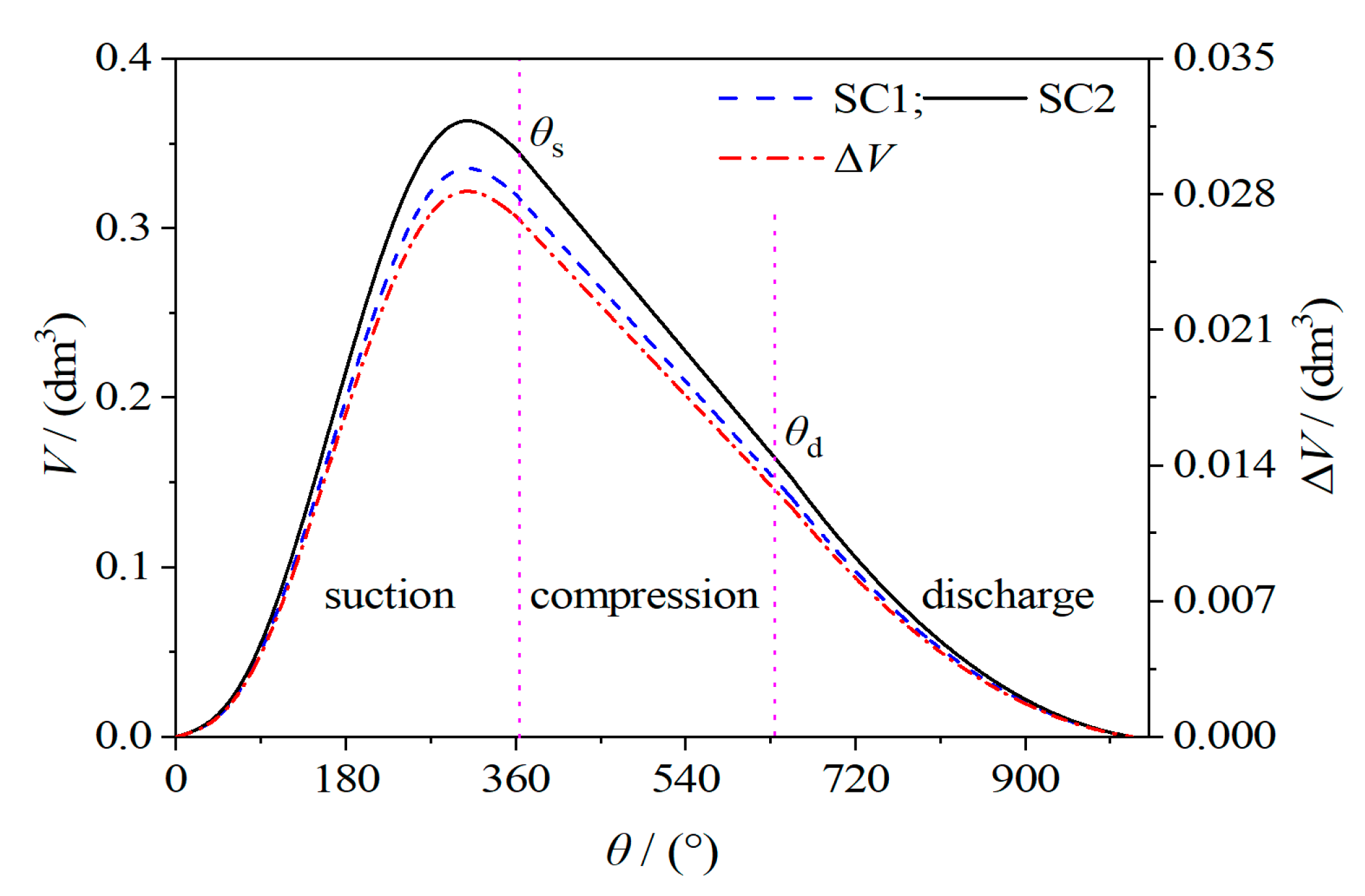
2.5.1. Volume of the Working Chamber
2.5.2. Temperature and Pressure
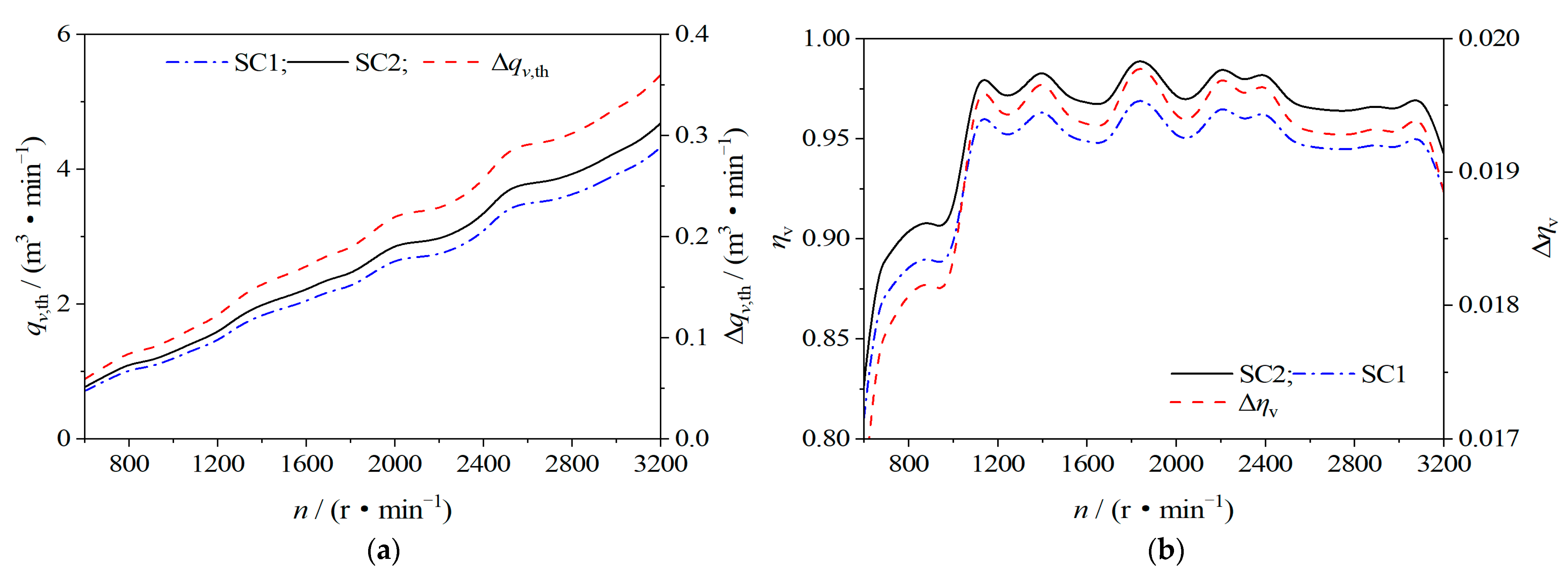
2.5.3. Theoretical Volume Flow and Volumetric Efficiency
3. Numerical Simulation of Double-Wrap Scroll Compressor
3.1. Governing Equation
3.2. Grid Division and Independence Verification
3.2.1. Fluid Domain Grid Division
3.2.2. Grid Independence Verification
3.3. Calculation Method and Boundary Conditions
3.4. Discussion and Analysis
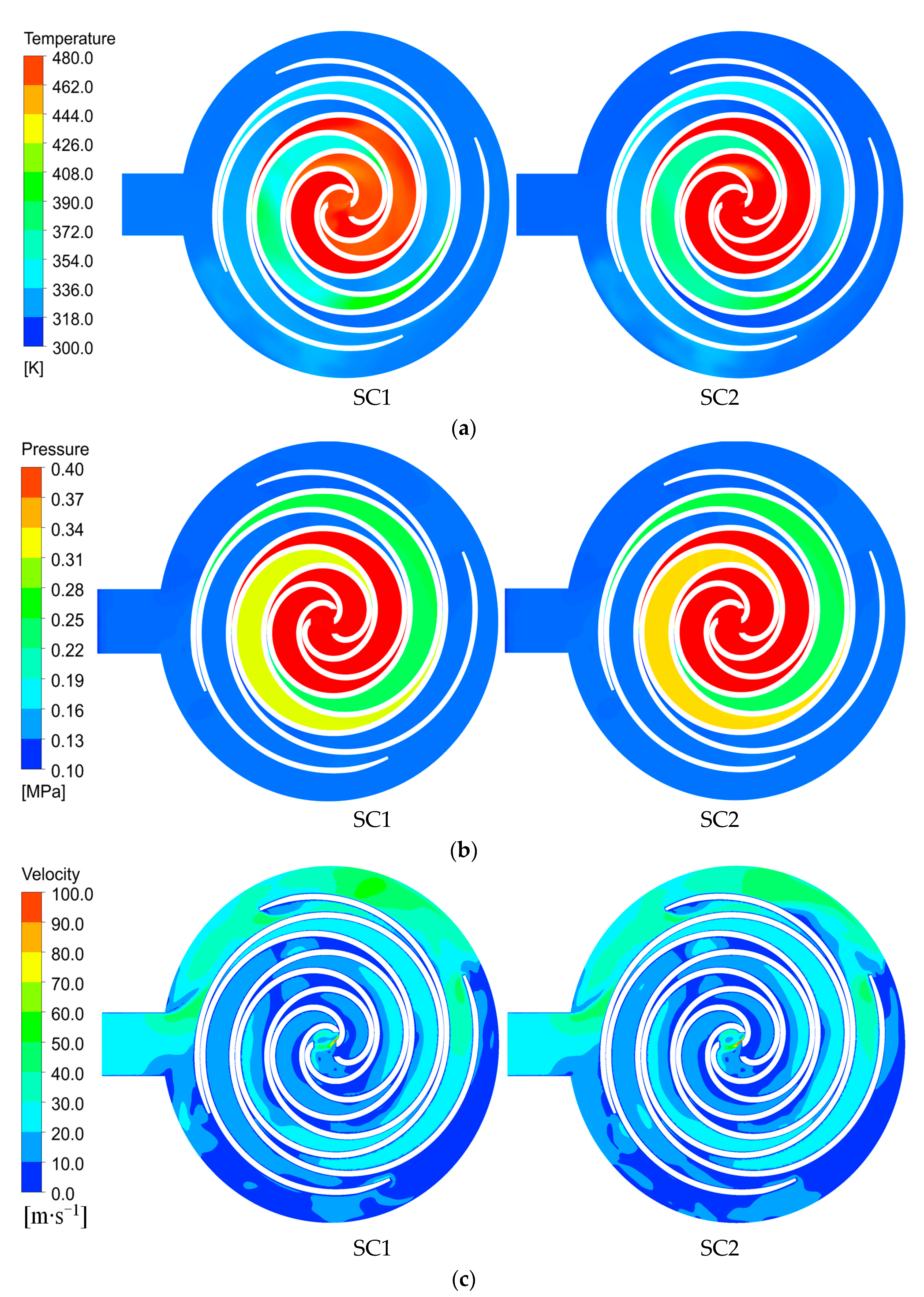
3.4.1. Distribution Contour of Fluid in the Working Chamber
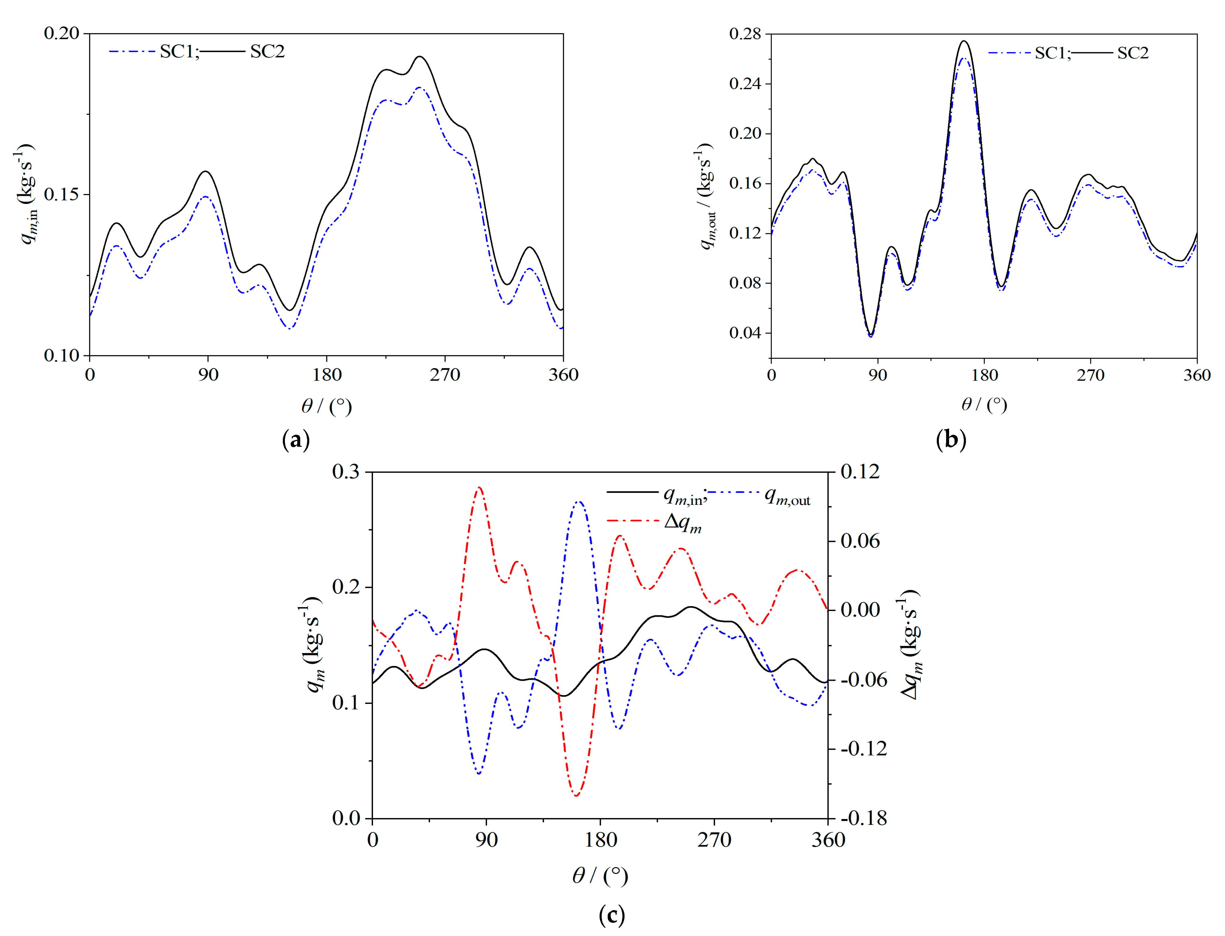
3.4.2. Inlet and Outlet Mass Flow
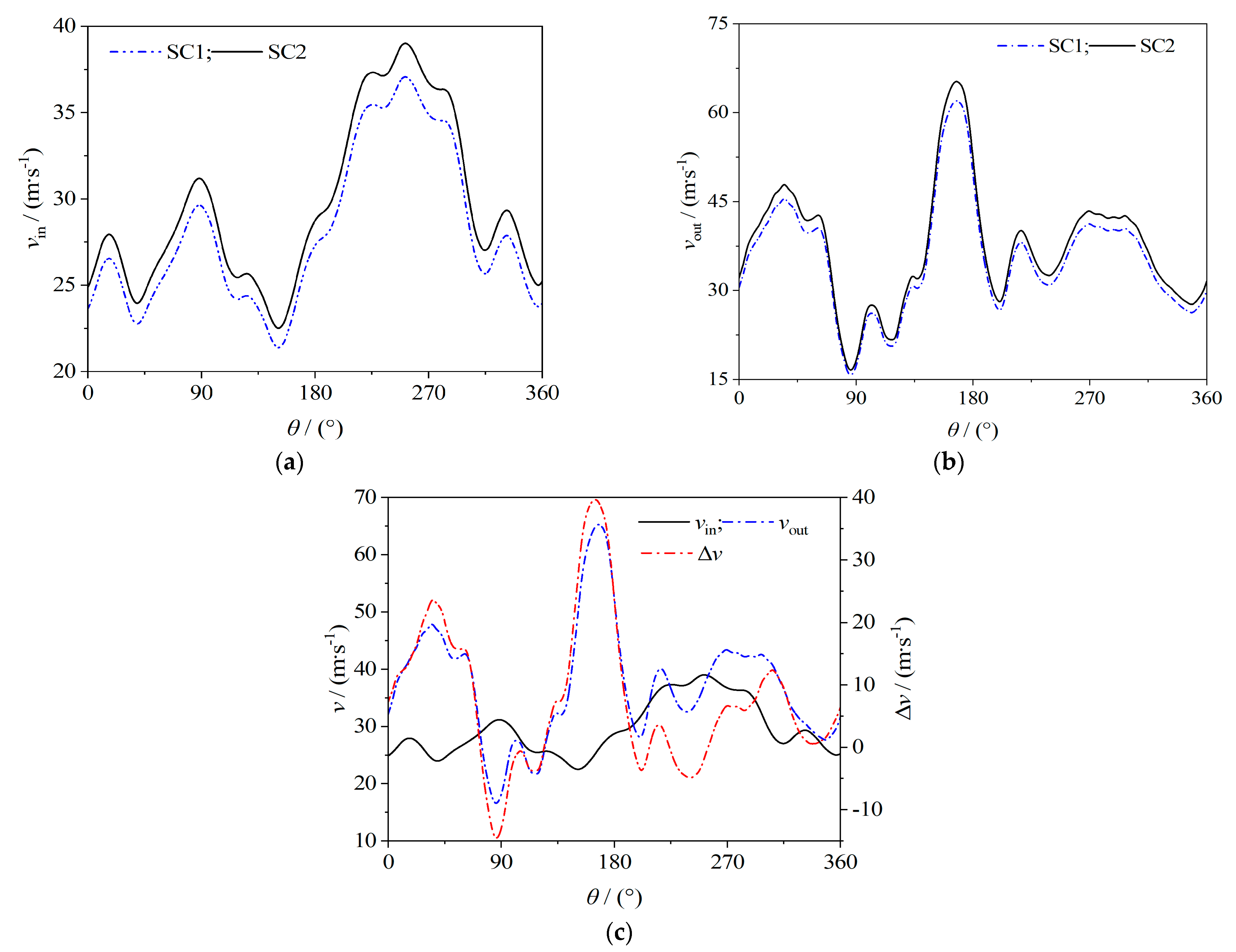
3.4.3. Inlet and Outlet Velocity
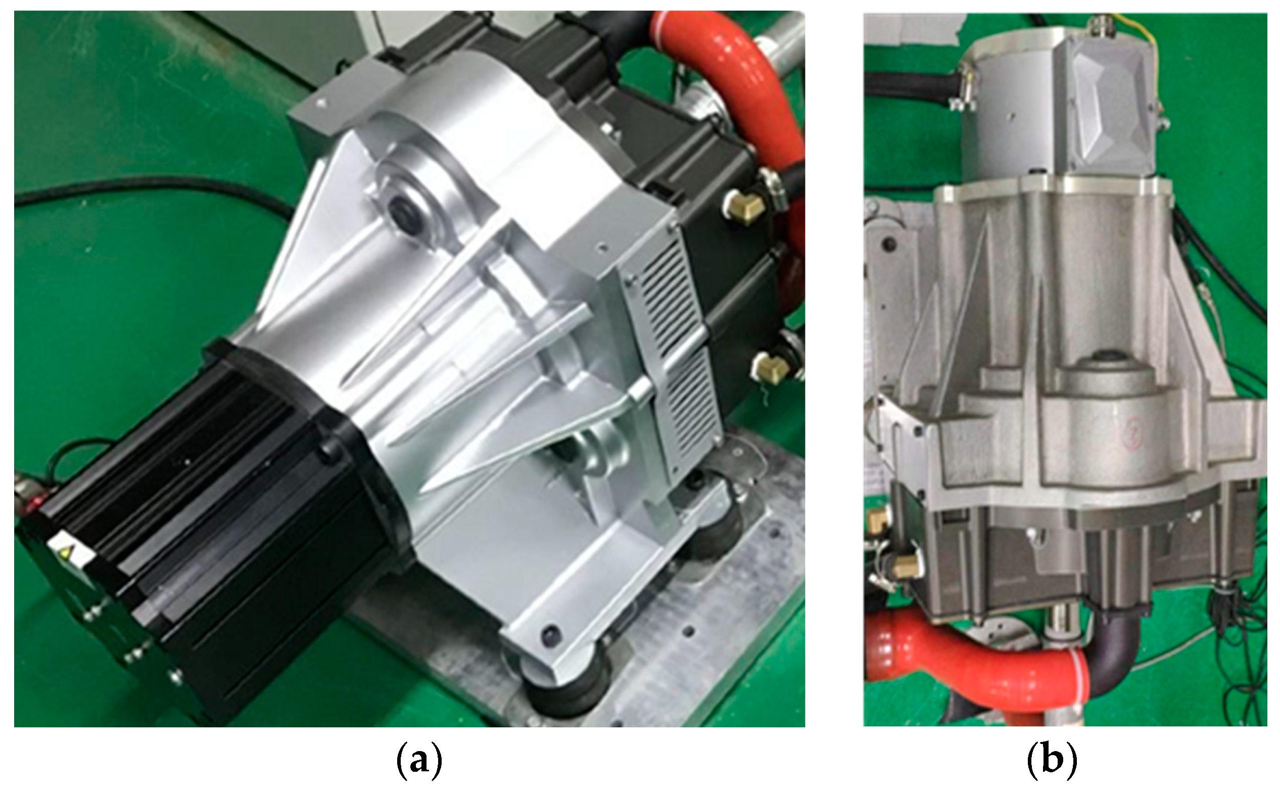
4. Test Research
4.1. Double-Wrap Scroll Compressor
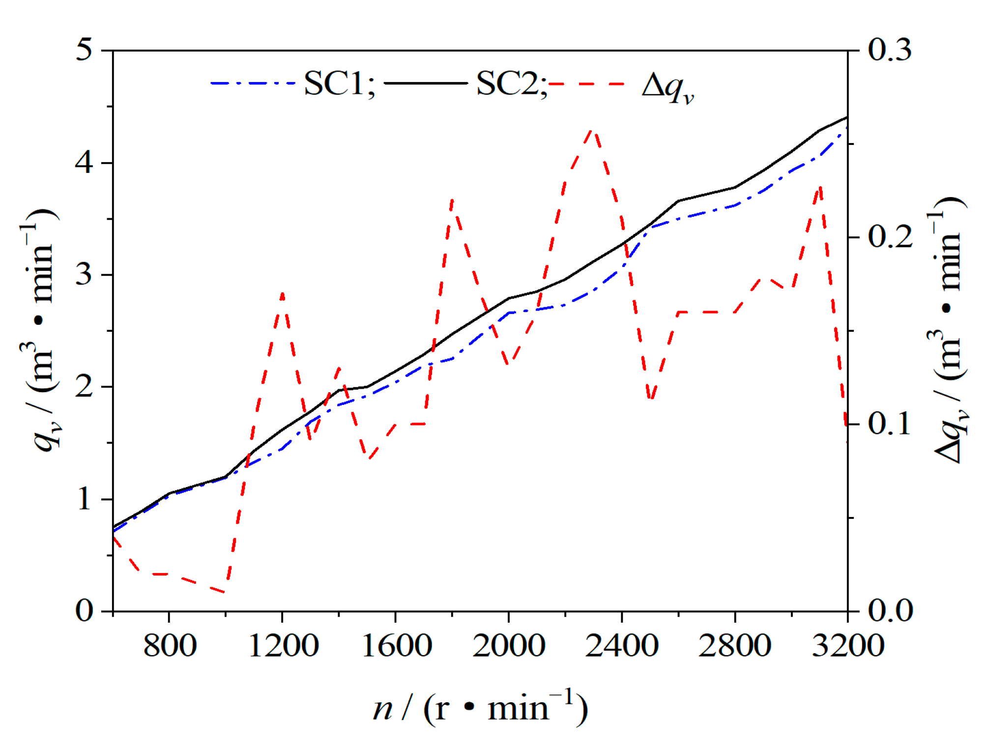
4.1.1. Volume Flow
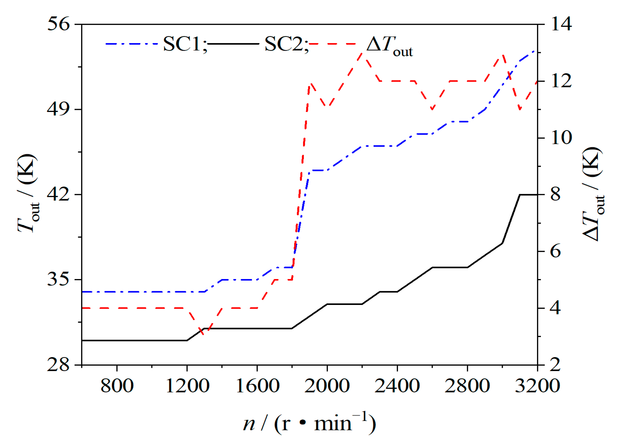
4.1.2. Discharge Temperature
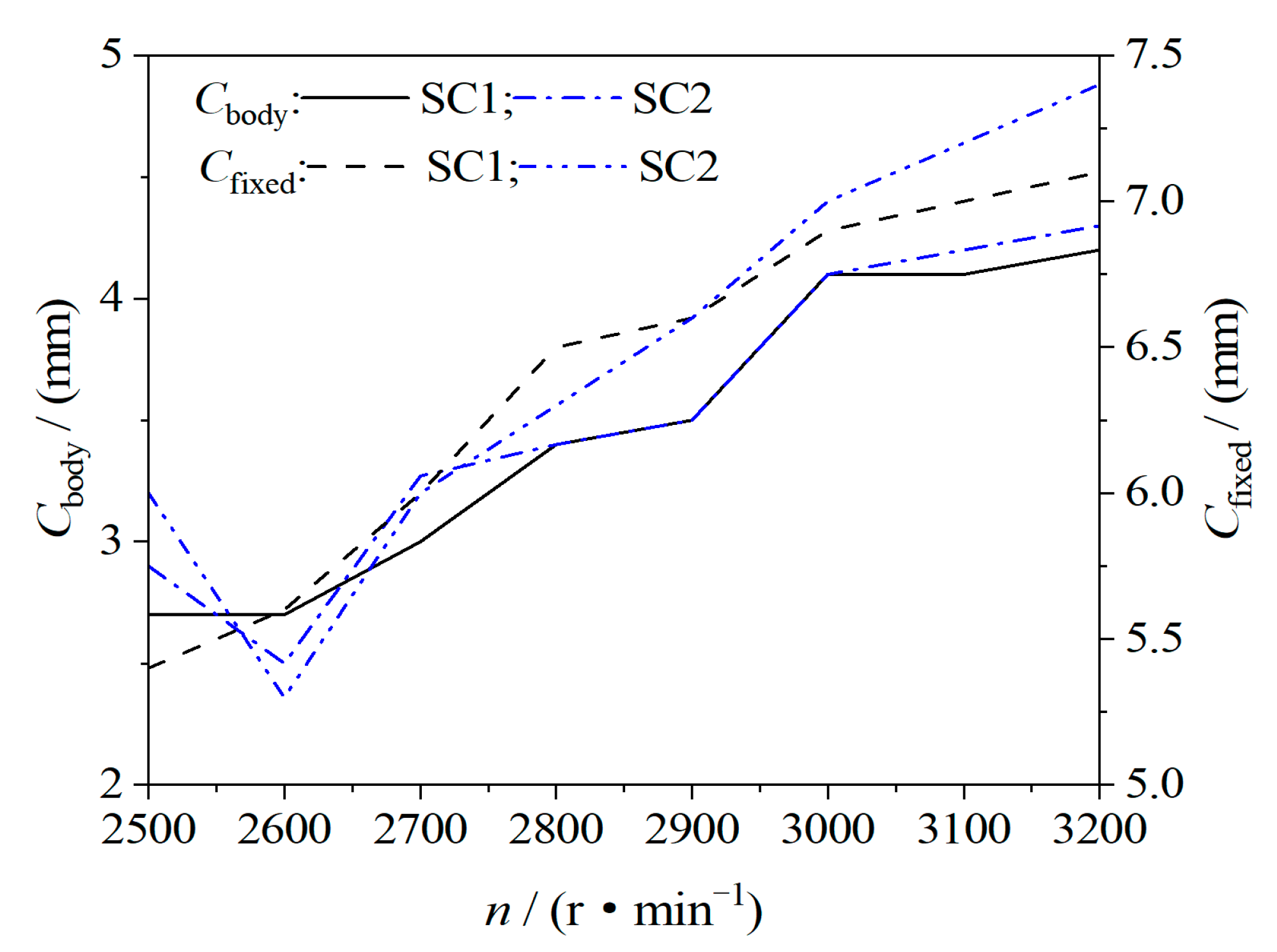
4.1.3. Vibration Value
4.1.4. Driving Motor Power and Current
4.2. Scroll and Screw Compressors
4.2.1. Volumetric Efficiency
4.2.2. Rotational Speed and Noise
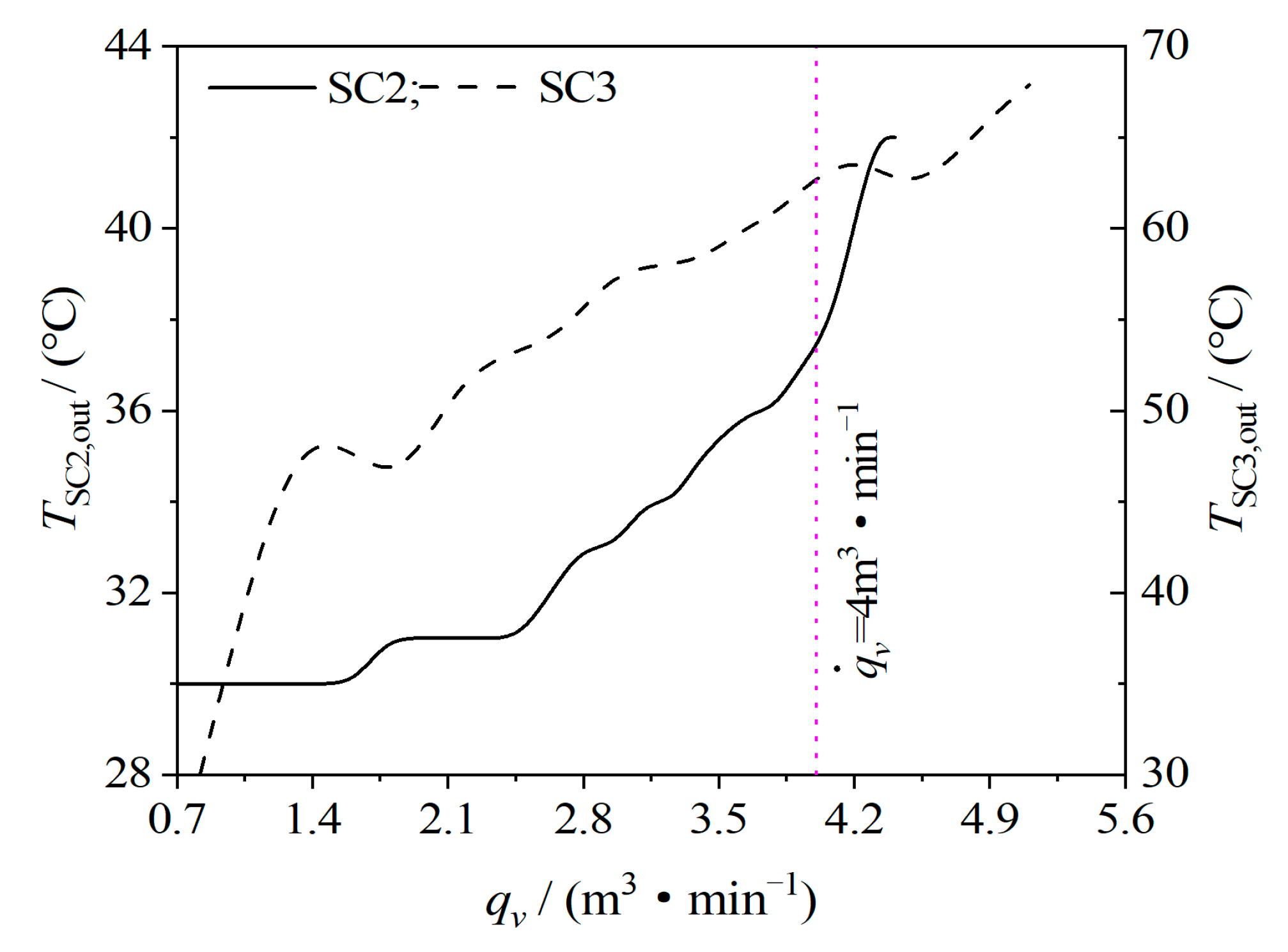
4.2.3. Discharge Temperature
5. Conclusions
- (1)
- The discharge pressure and volume flow are used as the objective function to measure the basic output performance parameters of the oil-free double-wrap scroll air compressor. The temperature, pressure, volume flow, and volume efficiency of the scroll compressor are all affected by the working chamber during the working process. The influence of volume is also affected by the basic geometric design parameters of the compressor.
- (2)
- As the double-wrap scroll compressor has four exhaust chambers and the discharge port is large, the temperature, pressure, and velocity of each discharge chamber vary inconsistently. The inlet and outlet mass flows reach the maximum at crankshaft orbiting angle 250° and 160°, respectively. The discharge opening reaches the maximum when the spindle rotates to 120~186°. The mass exchange of working fluids between adjacent working chambers has a greater influence on the temperature and flow rate in the working chamber and less influence on the pressure.
- (3)
- Based on the analysis and research of the built test platform, the maximum temperature of the SC2 discharge port was only 42 °C with liquid cooling measures for the scroll compressor and driving motor. After optimization, the scroll compressor is at a rated speed of 3000 r/min, the compressor discharge volume flow is 4.1 , and the discharge temperature after cooling is 38 °C, thus meeting the needs of the fuel cell air supply subsystem.
- (4)
- Screw compressors can only achieve the same discharge volume flow as scroll compressors at a rapid speed. At the same volume flow, the rotational speed, discharge temperature, and noise of scroll compressors are lower than screw compressors. Due to the increase in the diameter of the orbiting and fixed scroll discs of the oil-free double-wrap scroll compressor, the structure of the whole machine will increase accordingly, which will increase the power of the compressor drive motor. Double-wrap scroll compressors are suitable for applications with large displacement and low pressure ratio.
Author Contributions
Funding
Data Availability Statement
Conflicts of Interest
Abbreviations
| SC1 | Prototype 1—scroll compressor |
| SC2 | Prototype 2—scroll compressor |
| SC3 | Prototype 3—screw compressor |
| PEMFC | Proton Exchange Membrane Fuel Cells |
| HFC | Hydrogen Fuel Cell |
| CFD | Computational Fluid Dynamics |
| UDF | User Defined Function |
References
- Liu, M.Y.; Xiao, X.D.; Li, Q.; Luo, L.Y.; Ding, M.H.; Zhang, B.; Li, Y.X.; Zou, J.L.; Jiang, B.J. Recent progress of electrocatalysts for oxygen reduction in fuel cells. J. Colloid Interface Sci. 2021, 607, 791–815. [Google Scholar] [CrossRef] [PubMed]
- Xie, X.S.; Yang, W.J.; Shi, W.; Zhang, S.S.; Wang, Z.S.; Zhou, J.H. Life cycle assessment of technologies for hydrogen production—A review. Chem. Ind. Eng. Prog. 2018, 37, 2147–2158. [Google Scholar]
- Wiartalla, A.; Pischinger, S.; Bornscheuer, W.; Fieweger, K.; Ogrzewalla, J. Compressor expander units for fuel cell systems. SAE Trans. 2000, 109, 484–488. [Google Scholar]
- Shao, Z.G.; Yi, B.L. Developing Trend and Present Status of Hydrogen Energy and Fuel Cell Development. Bull. Chin. Acad. Sci. 2019, 34, 469–477. [Google Scholar]
- Ahmed, K.; Nikola, S.; Ian, S. Screw Compressors; Springer: Berlin/Heidelberg, Germany, 2007. [Google Scholar]
- Wang, Z.L.; Wang, H.; Wang, Z.M.; Li, Q.; Feng, Q.K. Theoretical study on heat transfer characteristics of single screw refrigeration compressor with Multicolumn envelope meshing pair. Appl. Therm. Eng. 2019, 166, 114635. [Google Scholar] [CrossRef]
- Gu, Z.L.; Yu, Y.Z.; Jiang, D.M. Improved Characteristics of Scroll Machines with Multiple Spiral. J. Xi′an Jiaotong Univ. 1998, 32, 90–93. [Google Scholar]
- Wang, J.; Li, X.Q. Construction Theories of Meshing Profile for Multi-Wraps Scroll Machinery. J. Mech. Eng. 2008, 44, 74–79. [Google Scholar] [CrossRef]
- Wang, J.; Ju, H.; Zhao, M.; Qu, Y. Influence of Wrap Number on Performance of Multi-Wrap Scroll Compressor. J. China Univ. Pet. (Ed. Nat.Sci.) 2009, 33, 118–122. [Google Scholar]
- Peng, B.; Zhang, Y.B.; Zhang, P.C.; Zhang, Y.B.; Yin, B. Effects of Various Profile Parameters on the Performance of a Double-Scroll Compressor. Chin. Hydraul. Pneum. 2020, 10, 145–150. [Google Scholar]
- Cardone, M.; Gargiulo, B. Numerical Simulation and Experimental Validation of an Oil Free Scroll Compressor. Energies 2020, 13, 5863. [Google Scholar] [CrossRef]
- Chang, J.C.; Chang, C.W.; Hung, T.C.; Lin, J.R.; Huang, K.C. Experimental study and CFD approach for scroll type expander used in low-temperature organic Rankine cycle. Appl. Therm. Eng. 2014, 73, 1444–1452. [Google Scholar] [CrossRef]
- Wang, J.; Song, Y.X.; Li, Q.; Zhang, D.H. Novel structured dynamic mesh generation for CFD analysis of scroll compressors. Proc. Inst. Mech. Eng. Part A J. Power Energy 2015, 229, 1007–1018. [Google Scholar] [CrossRef]
- Ooi, K.T.; Zhu, J. Convective heat transfer in a scroll compressor chamber: A 2-D simulation. Int. J. Therm. Sci. 2004, 43, 677–688. [Google Scholar] [CrossRef]
- Wang, J.; Song, Y.X.; Jiang, Y.; Li, Q.; Zhang, D.H. Numerical simulations of internal flow fields for scroll compressors based on structured dynamic meshes. J. Eng. Thermophys. 2016, 37, 309–313. [Google Scholar]
- Wang, J.; Song, Y.X.; Zha, H.B.; Li, Q. 3D Numerical Simulation and Study of Discharge Process for Scroll Compressors. J. Eng. Thermophys. 2016, 37, 766–769. [Google Scholar]
- Sun, S.H.; Wu, K.; Guo, P.C.; Yan, J.C. Analysis of the three-dimensional transient flow in a scroll refrigeration compressor. Appl. Therm. Eng. 2017, 127, 1086–1094. [Google Scholar] [CrossRef]
- Zhao, R.C.; Li, W.H.; Zhuge, W.L. Unsteady characteristic and flow mechanism of a scroll compressor with novel discharge port for electric vehicle air conditioning. Int. J. Refrig. 2020, 118, 403–414. [Google Scholar] [CrossRef]
- Fadiga, E.; Casari, N.; Suman, A.; Pinelli, M. Structured Mesh Generation and Numerical Analysis of a Scroll Expander in an Open-Source Environment. Energies 2020, 13, 666. [Google Scholar] [CrossRef] [Green Version]
- Cavazzini, G.; Giacomel, F.; Ardizzon, G.; Casari, N.; Fadiga, E.; Pinelli, M.; Suman, A.; Montomoli, F. CFD-based optimization of scroll compressor design and uncertainty quantification of the performance under geometrical variations. Energy 2020, 209, 118382. [Google Scholar] [CrossRef]
- Rak, J.; Pietrowicz, S. Internal flow field and heat transfer investigation inside the working chamber of a scroll compressor. Energy 2020, 202, 117700. [Google Scholar] [CrossRef]
- Cavazzini, G.; Giacomel, F.; Benato, A.; Nascimben, F.; Ardizzon, G. Analysis of the Inner Fluid-Dynamics of Scroll Compressors and Comparison between CFD Numerical and Modelling Approaches. Energies 2021, 14, 1158. [Google Scholar] [CrossRef]
- Zheng, S.Y.; Wei, M.S.; Song, P.P.; Hu, C.X.; Tian, R. Thermodynamics and flow unsteadiness analysis of trans-critical CO2 in a scroll compressor for mobile heat pump air-conditioning system. Appl. Therm. Eng. 2020, 175, 115368. [Google Scholar] [CrossRef]
- Zheng, S.Y.; Wei, M.S.; Chenxing, H.U.; Song, P.P.; Tian, R. Flow characteristics of tangential leakage in a scroll compressor for automobile heat pump with CO2. Sci. China Technol. Sci. 2021, 64, 971–983. [Google Scholar] [CrossRef]
- Wang, J.; Cui, S.J.; Feng, H.Z.; Li, H.X.; Sha, R.D. Construction and Simulation of An Asymmetric Twin-Wrap Profile for Scroll Compressor. J. Eng. Thermophys. 2021, 42, 386–392. [Google Scholar]
- Versteeg, H.K.; Malalasekera, W. An Introduction to Computational Fluid Dynamics: The Finite Volume Method; Pearson Education: London, UK, 2007. [Google Scholar]
- Park, I.; Choi, S.; Lee, B.; Yoo, B. Scroll Compressor with an Arcuate and a Logarithmic Spiral Sections. U.S. Patent 9,605,675B2, 2 March 2017. [Google Scholar]


| Paraments | Symbol | Value | Units |
|---|---|---|---|
| Base circle radius | 9.231 | mm | |
| Involute angle | 0.244 | rad | |
| Revolution radius | 10.000 | mm | |
| Starting angle of involute | 0.785 | rad | |
| End angle of involute | 3.336 | rad |
| Paraments | Symbol | Value | Units |
|---|---|---|---|
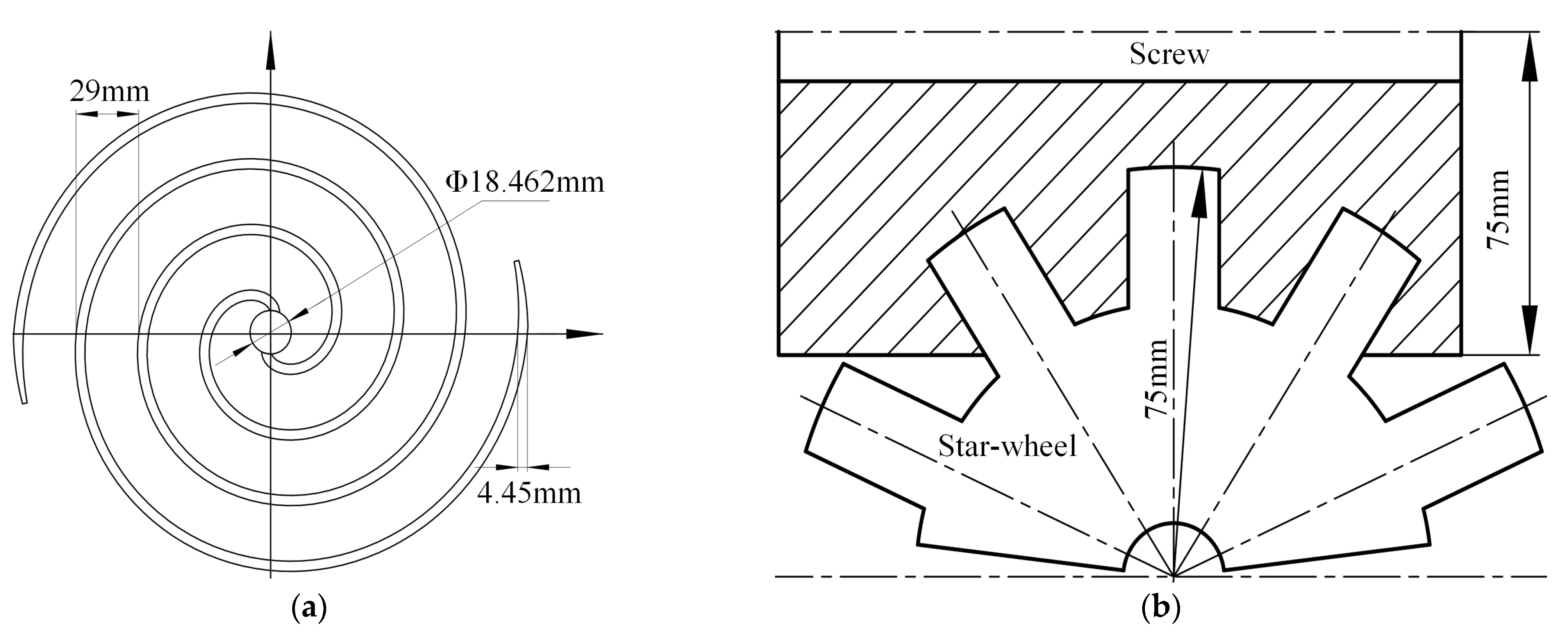
| Screw tooth groove number | 6 | - | |
| Number of star gears | 11 | - | |
| Screw tip circle diameter | 150 | (mm) | |
| Diameter of tip circle of star gear | 150 | (mm) | |
| Screw length | 153 | (mm) |
| Number | Total Elements | Total Nodes |
|---|---|---|
| Inlet pipe | 23,337 | 10,189 |
| Working chamber | 5,613,089 | 2,608,404 |
| Outlet pipe | 80,100 | 13,762 |
| Total | 5,716,526 | 2,635,355 |
Publisher’s Note: MDPI stays neutral with regard to jurisdictional claims in published maps and institutional affiliations. |
© 2021 by the authors. Licensee MDPI, Basel, Switzerland. This article is an open access article distributed under the terms and conditions of the Creative Commons Attribution (CC BY) license (https://creativecommons.org/licenses/by/4.0/).
Share and Cite
Sun, J.; Peng, B.; Zhu, B. Performance Analysis and Test Research of PEMFC Oil-Free Positive Displacement Compressor for Vehicle. Energies 2021, 14, 7329. https://doi.org/10.3390/en14217329
Sun J, Peng B, Zhu B. Performance Analysis and Test Research of PEMFC Oil-Free Positive Displacement Compressor for Vehicle. Energies. 2021; 14(21):7329. https://doi.org/10.3390/en14217329
Chicago/Turabian StyleSun, Jian, Bin Peng, and Bingguo Zhu. 2021. "Performance Analysis and Test Research of PEMFC Oil-Free Positive Displacement Compressor for Vehicle" Energies 14, no. 21: 7329. https://doi.org/10.3390/en14217329
APA StyleSun, J., Peng, B., & Zhu, B. (2021). Performance Analysis and Test Research of PEMFC Oil-Free Positive Displacement Compressor for Vehicle. Energies, 14(21), 7329. https://doi.org/10.3390/en14217329