Article

An Approach to Dynamic Disaster Prevention in Strong Rock Burst Coal Seam under Multi-Aquifers: A Case Study of Tingnan Coal Mine

1
North China Institute of Science and Technology, Langfang 065201, China
2
Shaanxi Changwu Tingnan Coal Industry Co., Ltd., Xianyang 713602, China
3
Shenhua Xinjiang Energy Co., Ltd., Urumchi 830027, China
*
Author to whom correspondence should be addressed.
Energies 2021, 14(21), 7287; https://doi.org/10.3390/en14217287
Submission received: 13 October 2021 / Revised: 29 October 2021 / Accepted: 1 November 2021 / Published: 3 November 2021
(This article belongs to the Special Issue Rock Burst Disasters in Coal Mines)

Abstract

:
In order to prevent the multi-dynamic disasters induced by rock burst and roof water inrush in strong rock burst coal seams under multi-aquifers, such as is the case with the 207 working face in the Tingnan coal mine considered in this study, the exhibited characteristics of two types of dynamic disasters, namely rock burst and water inrush, were analyzed. Based on the lithology and predicted caving height of the roof, the contradiction between rock burst and water inrush was analyzed. In light of these analyses, an integrated method, roof pre-splitting at a high position and shattering at a low position, was proposed. According to the results of numerical modelling, pre-crack blasting at higher rock layers enables a cantilever roof cave in time, thereby reducing the risk of rock burst, and pre-crack blasting at underlying rock layers helps increase the crushing degree of the rock, which is beneficial for decreasing the caving height of rock layers above goaf, thereby preventing the occurrence of water inrush. Finally, the proposed method was applied in an engineering case, and the effectiveness of this method for prevention and control of multi-dynamics disasters was evaluated by field observations of the caving height of rock layers and micro-seismic monitoring. As a result, the proposed method works well integrally to prevent and control rock burst and water inrush.

1. Introduction

Rock burst is one of the serious mining hazards threatening the safety, economics and productivity of underground engineering around the world, such as in coal mines, metal mines, waste repositories, etc. [1,2] and has also occurred in civil tunnels in recent years [3,4]. In China, rock burst has occurred frequently in coal mining due to increasing mining depths, which has led to a large amount of personal casualties and equipment damage. Moreover, rock burst may induce secondary dynamic disasters, such as water inrush and gas explosion [5,6]. To solve the hazards induced by rock burst and water inrush, some scholars at home and abroad have conducted a series of studies. Most of the researches on the prevention and control of rock burst [7,8,9,10] and water inrush [11,12,13,14,15] are focused on the single disaster field. However, the mining conditions of mines are complicated, and most accidents are combined with multiple disasters. For example, among 132 rock bursts that have occurred in coal mines in China, a considerable portion of coal mines where rock burst has occurred have water-rich roof strata above the rock burst coal seams. According to our investigation, there are 1 extremely complex hydrogeological mine and 13 complex hydrogeological mines among 22 rock bursts in coal mines in Shananxi Province, accounting for 63.6%, which were mainly induced in the sandstone roofs of the Luohe aquifer and Yijun aquifer. Therefore, it is far from enough to consider a single disaster, and multi-dynamic disasters also need to be studied. In recent years, the following research achievements have been conducted in the research field of multi-dynamic disasters.
Jiang et al. [16,17,18] studied the stress evolution rules of a multi-aquifer and a coal seam in light of the dynamic phenomenon during the process of drainage in the deep roadway of the Ordos mining area and revealed the mechanism of rock burst induced by drainage. Shi et al. [19,20] illuminated the relationship among mine ground pressure, rock burst and roof water inrush on the basis of analysing the source of roof water inrush in a coal seam. Taking the 1301 working face as the engineering background in the Yuncheng coal mine, Li et al. [21,22] determined that the hydrophobic pressure boost zone was an importance force source of rock burst and revealed the disaster-causing mechanism under the complex condition of “high stress-strong disturbance-weak rock mass” by the means of theoretical analysis, field monitoring, engineering experiments and numerical simulation. Han et al. [23] analyzed the internal relationship between coal-rock dynamic disasters, such as coal and gas outburst, rock burst and floor water inrush, and the ground stress field in the Kailuan mining area, based on a ground stress test. On the basis of studying the relationship between the stress characteristics of a working face and the height of a roof fracture zone, Ti et al. [24] proposed a method to determine the height of an overburden rock-fracture zone by combining the stress characteristics of the roof and the comprehensive column chart of the overburden rock. Xu and Zhu et al. [25,26] put forward a new method to predict the height of a water-conducting fracture zone based on the position of the overburden key layers on the basis of studying the rules of influence of overburden key layers on the development height of a water-conducting fracture zone. The research results showed that the position of overburden key layers would affect the development height of a water-conducting fracture zone. Sheng et al. [27] studied how to ensure the reliable and stable operation of a mine drainage system in the case of a mine impact disaster, summarized the general principles for the design of a similar mine drainage system, and provided a new idea for the design and construction of a mine drainage system in the case of mine impact disasters.
The previous research mainly illustrated the mechanisms, characteristics and prevention and control technologies of rock burst and water inrush from the aspect of theoretical models and mechanical analyses, which enriched relevant theories and were significant to the prevention and control of dynamic disasters. However, previous research mainly focused on a single disaster, while the multi-dynamic disaster-causing mechanisms are intricate, and existing technologies have been unable to solve these problems before now. In light of this, it is far from enough to think about single disasters for these mines. Therefore, technologies that integrate prevention and control of multi-dynamic disasters are urgently desired for these coal mines.
This paper considered the 207 working face in the Tingnan Coal Mine as a study example, combined theories with numerical simulation and field work technologies to analyze the key contradiction between rock burst and water inrush, proposed an integrated method (roof pre-splitting at a high position and shattering at a low position), and put the method into practice, which has gained certain achievements.

2. Engineering Background

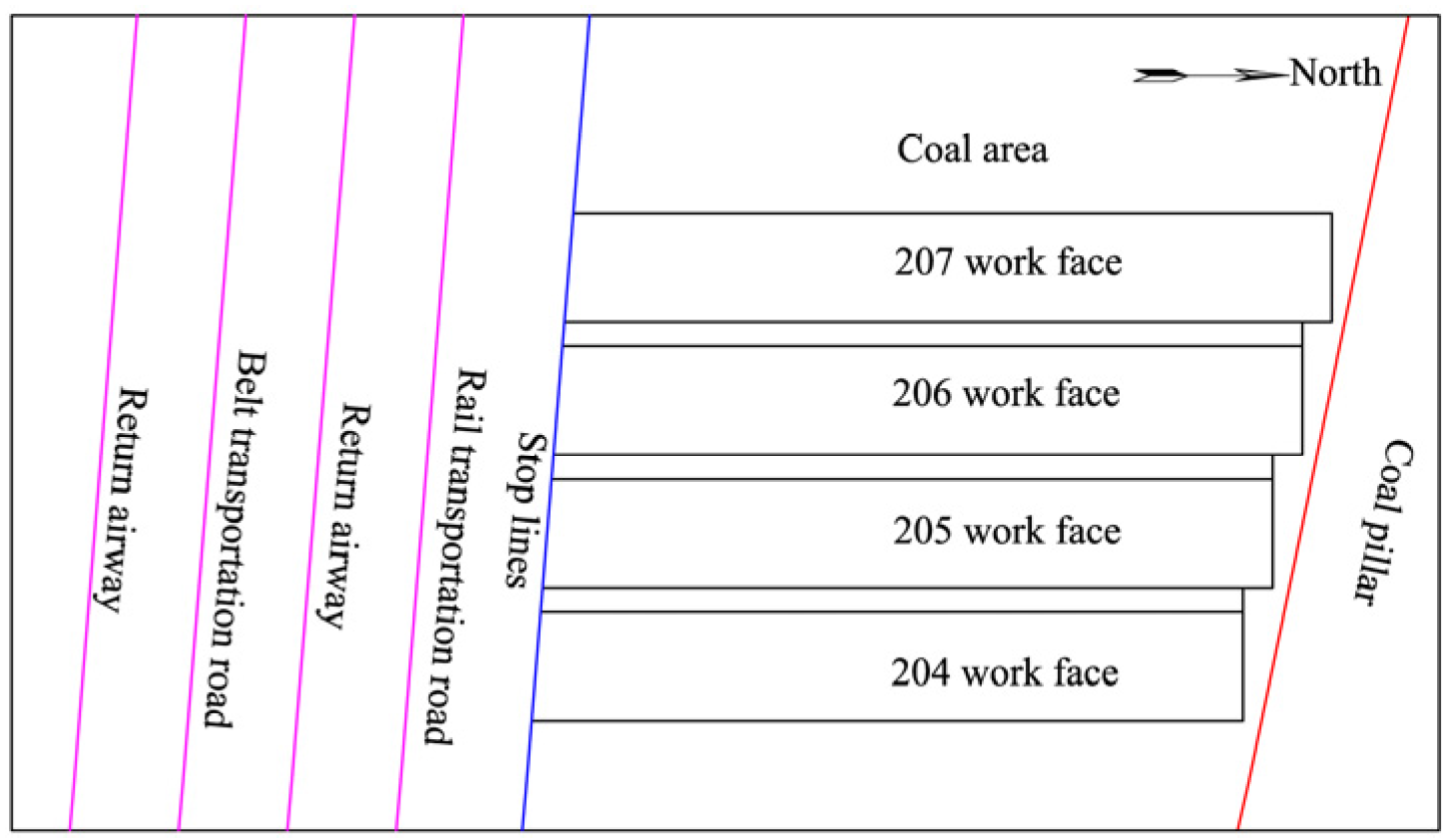
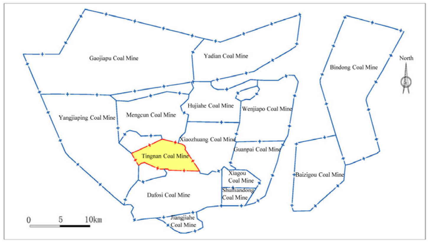
2.1. Geological Feature

The Tingnan coal mine is located at the center of the Binxian-Changwu area, Shanaxi Province, with the Dafosi coal mine in the south, the Xiaozhuang coal mine in the east, the Mengcun coal mine in the north and the Yangjiaping coal mine in the west (please see Figure 1). Its approved annual production is 5 million tones; the Jurassic No. 4 coal seam is the only excavating resource at present. The buried depth of the No. 2 panel area is 432–729 m; at present, the mining activities at the 204, 205 and 206 working faces have been completed, and mining activities are mainly concentrated at the 207 working face. The diagrammatic sketch of working faces at the No. 2 panel area is shown in Figure 2. The average thickness and dip angle of the coal seam are 11.05 m and 4°, respectively. The mine hydrogeological type is “complex” and the main aquifer affected by mining is the Luohe aquifer. The lithology is mainly medium sandstone and coarse sandstone. The permeability coefficient of the Luohe aquifer is 0.0241 m/d, and the distance between the top plate of the No. 4 coal seam and the bottom boundary of the Luohe aquifer is about 173.5–176.0 m. Rock burst and water inrush are the dominant dynamic disasters in the Tingnan coal mine, which have seriously affected the safety of mine production.

2.2. History of Multi-Dynamic Disasters
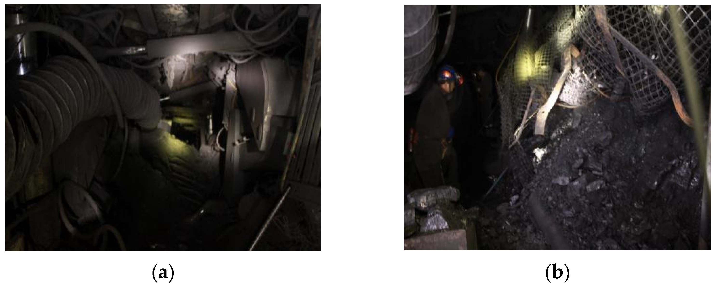
2.2.1. Rock Burst

At present, the mine impact phenomenon is mainly concentrated in the No. 2 panel area. From April 2014 to March 2016, there were two impact phenomena at the 205 working face and 43 impact phenomena at the 206 working face in total, which mainly caused humps at the tunnel floor, subsidence at the tunnel roof and wall caving. One of the most serious accidents occurred at the 205 working face, which caused a 1.2 m convergence at the tunnel roof, a 0.7 m hump at the tunnel floor and a single hydraulic prop inclination, parts of which damage are shown in Figure 3a,b.

2.2.2. Water Inrush

As shown in Table 1, there was no water inrush at the 201 working face. The normal water inflow at the 204 working face is 150–250 m3·h−1, and the maximum water inflow is 270 m3·h−1, which suggests that there is not an obvious, sudden increase in water inflow during mining at the 204 working face. The normal water inflow at the 205 working face was 150–250 m3·h−1, but when the mining distance reached 616 m, the maximum water inflow was 504 m3·h−1 and maintained above 300 m3·h−1 for seven days, which caused a huge threat to mine safety. Furthermore, the normal water inflow at the 206 working face was 240–380 m3·h−1, but when the mining distance reached 1423 m, the maximum water inflow was 490 m3·h−1, which had a great impact on mine production.
In conclusion, the multi-dynamic disaster in the No. 2 panel area was mainly a combination of rock burst and water inrush, and rock burst was manifested as roof impact. If the suspended roof cannot be treated properly in time, it may induce rock burst and water inrush. Specific reasons for multi-dynamic disasters are introduced as following subsections.

3. Analysis on the Multi-Dynamic Disasters

3.1. Cause Analysis of Rock Burst

The depth of the No. 4 coal seam is between 508 m and 680 m; in light of this, the hazard index of rock burst increases from 0.1 to 0.45, which suggests that the mining depth is a key factor for rock burst. According to the test results, the No. 4 coal seam and roof have a strong burst tendency and the floor has a weak burst tendency, which are the factors for rock burst. A geological investigation by borehole (Table 2) suggests that there are two types of key layers with a thickness of more than 30 m above the coal seam, namely the main key strata and the inferior key strata [28,29,30,31,32], which may form a suspended roof of goaf and even lead to rock burst.

3.2. Cause Analysis of Water Inrush

After the mining of the 204 working face, two boreholes, namely D1 and D2, were drilled from the surface to detect the caving zone and the fracture zone. The result suggests that the ultimate rupture distance of the main key stratum of the Luohe aquifer is 164 m according to the beam fracture calculation. Corresponding to the plate fracture calculation, when the working face width is 200 m and the working face has been pushed to 367 m, the main key layer has broken. Therefore, from a theoretical point of view, it can be concluded that the Luohe Aquifer has ruptured.
Moreover, in light of the results of D2 drilling TV images, cracks were found at 119.60 m, 386.90 m, 392.59 m, etc, (please see Figure 4). At the same time, in the process of drilling, the phenomenon of drill dropping (a sign of delamination) was found at the bottom of the Luohe aquifer (the drilling depth is 389.37 m), which can also indicate that the sandstone layers of the Luohe aquifer were bent or even damaged to a certain extent after the mining of the 204 working face. This phenomenon would be further aggravated with the subsequent mining activities at the 205 and 206 working faces.
To prevent water inrush, the height of the water-conducting fracture zone must be determined in advance [33,34,35,36]. The overlying rock strata generally form a caving zone, a fracture zone and a bending zone after coal mining. According to a general empirical formula, Equations (1)–(3) [37] can be applied to predict the height of the caving zone and the fracture zone, in which M represents the average mining thickness of coal seams in meters; k represents the rock loss coefficient; α represents the coal seam dip angle in degrees; h1 represents the caving zone height; h2 represents the fracture zone height; and h3 represents the water-conducting fracture zone (the sum of the height of the caving zone and the fracture zone).
h 1 = M ( k 1 ) cos α
h 2 = ( 1 3 ) h 1
h 3 = h 1 + h 2
The mining thickness at the 207 working face is 9 m, the average dip angle is 4°, the immediate roof is sandy mudstone, and the main roof is a combination of coarse sandstone and fine sandstone. To predict the height of the caving zone and the water-conducting fracture zone, corresponding to the actual geological condition, take M as 9 m; take k as 1.2 m; and take α as 4°. It can be calculated that the height of the caving zone is 45.1 m, the height of fracture zone is 45.1–135.3 m and the height of the water-conducting fracture zone is 90.2–180.4 m.
According to Equations (1)–(3), the relationship between the water-conducting fracture zone height and the rock-shattering expansion coefficient can be calculated, as shown in Figure 5. When the rock-shattering expansion coefficient increases to 1.3, the height of the water-conducting fracture zone is about 30.07–90.21 m; if the rock-shattering expansion coefficient increases to 1.4, the height of the water-conducting fracture zone will reduce to 67.65 m. It can be seen that blasting rock strata to promote its shattering expansion coefficient has an obvious effect of reducing the height of the water-conducting fracture zone.
The damage degree of the overlying strata is more serious under high-intensity mining conditions. According to a previous investigation (which has been clarified) in the Wuyang coal mine, which has a similar mining thickness, the maximum height of the water-conducting fracture zones are 114.67 m by fully mechanized top coal caving, 83.9 m by fully mechanized slicing mining, and 49.6 m by conventional mining. The maximum height of the water-conducting fracture zone by fully mechanized top coal caving is 1.37 times of that by fully mechanized slicing mining, and is 2.31 times of that by conventional mining. Due to the lack of observation data of the water-conducting fracture zone by fully mechanized top coal caving and fully mechanized slicing mining, there is no unified calculation available at present. Based on the previous research from the Kailuan, Yanzhou, Huainan, Kangping, Tongchuan, Longkou and other mining areas, which have been clarified by the mines, the height of the water-conducting fracture zone can be calculated according to the following formulas under the high intensity conditions of fully mechanized top coal caving and fully mechanized slicing mining: M is the effective mining thickness of the coal seam in meters; n is the number of mining layers. The intensity of overburden rock layers at the 207 working face is between soft and medium hard rock. According to Formulas (5) and (6) [37], the height of the water-conducting fracture zone is 100–190 m, which has exceeded the predicted height. In addition, during the mining activities of the 207 working face, continuous goaf will be formed in the 204, 205 and 206 working faces and the degree of damage to the rock strata will be more serious, which will increase the risk of water inrush at the 207 working face.
Hard   rock           H l i = 30 M n + 10
                              Medium   hard   rock           H l i = 20 M n + 10
Soft   rock           H l i = 10 M n + 10
Based on the above analysis, the hard, thick roof must be treated to prevent rock burst and to avoid the height of roof damage reaching the multi-aquifers. Motivated by this determination, this paper proposes a new prevention and control method. Specific operations are exhibited in the following sections.

4. The Approach to Prevention and Control of Multi-Dynamic Disasters

The ideas of pre-splitting at a high position and shattering at a low position mainly include the following two aspects: One is pre-splitting at a high rock strata to promote the roof caving in time, which can decrease the risk of rock burst due to the accumulation of a large amount of elastic potential energy [38,39,40,41,42,43]. The other is blasting at a low position to increase the crushing degree of rock [44,45,46], which helps fill goaf effectively and reduce the height of the caving zone. In order to verify the feasibility of this proposed method, numerical modelling of the pre-splitting and shattering measurements was implemented; detailed information and a numerical simulation analysis are introduced in the following subsections.

4.1. Numerical Simulation

The suspended roof will be deformed because of the goaf and will even generate different kinds of cracks and blocks. Therefore, the discrete element method needs to be applied to analyze this situation. 3DEC can be used to analyze and simulate the destruction and change in the overlaying strata above goaf in terms of displacement.

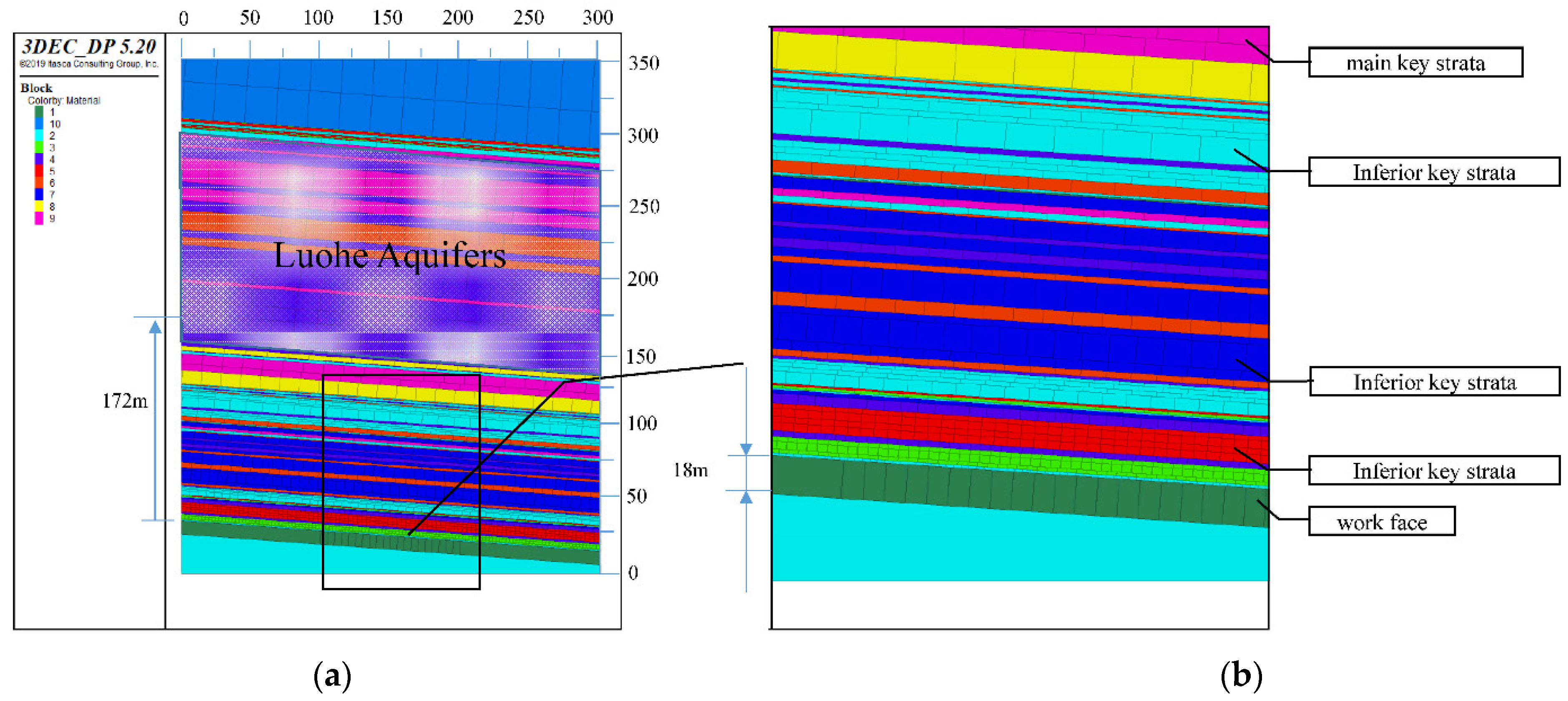
4.1.1. Model Characteristics and Physical Parameters

Corresponding to the lithological structure of the 207 working face, a numerical model was built, as displayed in Figure 6a, which is a full-scale model with a length of 300 m, a width of 10 m and a height of 350 m. In light of the field data, the distance between the Luohe aquifer and the No. 4 coal seam is 172 m, the height of the working face is 18 m; the main key strata and inferior key strata are displayed in Figure 6b. Physical and mechanical parameters of each coal or rock layer are shown in Table 3.

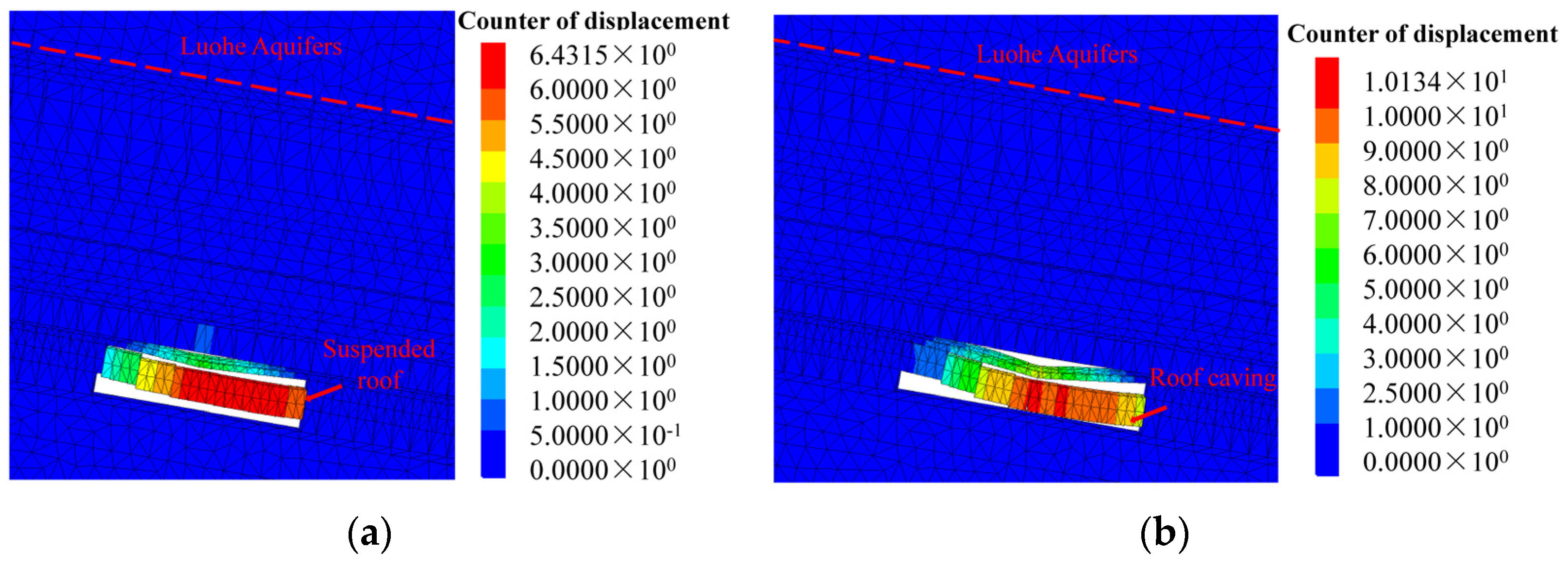
4.1.2. The Caving Process by Conventional Mining

Figure 7a,b show the process of caving the roof by conventional mining; when the working face is pushed to 60 m, a large area of suspended roof forms above the goaf. When the working face is pushed to 70 m, the suspended roof suddenly collapses, and displacement varies from 6.431 m to 10.134 m. Therefore, under conventional mining conditions, hard and thick roof strata are difficult to collapse. During the process of mining work, the roof cannot collapse in time, resulting in a large area of suspended roof, which will greatly increase the risk of rock burst.

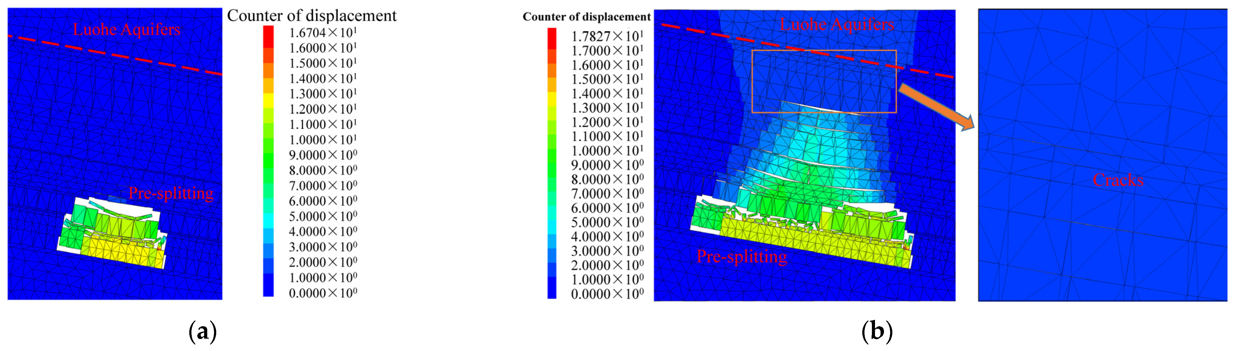
4.1.3. The Caving Process by Pre-Splitting at Overlying Strata

Figure 8a shows the caving process of overlying rock strata when the mining distance is 50 m. Figure 8b suggests that when the working face is pushed to 100 m, the cracks have reached the multi-aquifers, which may induce water inrush at the roof. Therefore, it is necessary to consider the relationship between the roof treatment and the rock fracture development height so that the occurrence of rock burst can be prevented to the maximum extent, while cracks cannot reach aquifers.

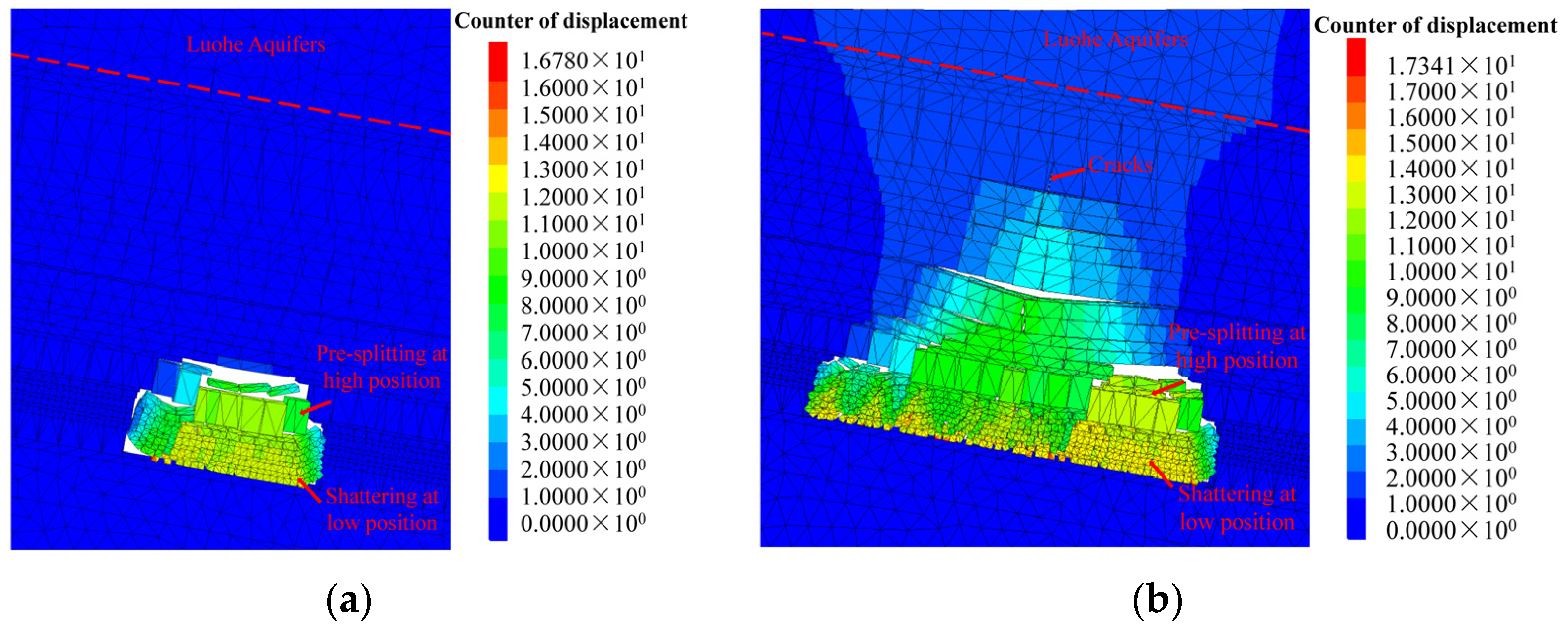
4.1.4. The Caving Process by Pre-Splitting at High Position and Shattering at Low Position

Through numerical simulation, two methods, namely roof pre-splitting at a high position and shattering at a low position were analyzed under conventional mining conditions. The results are shown in Figure 9a,b. The pre-splitting blasting is carried out at the upper rock strata to make the roof cave in time, and exploding the lower rock strata increases the rock expansion coefficient, so that it can fill more space and decrease the height of the caving zone and the water-conducting fracture zone at overlying rock, so as to realize the integrated prevention and control of rock burst and water inrush.
From simulation results, to prevent and control rock burst and water inrush integrally, it is necessary to promote the overlying rock strata collapse in time to avoid forming a suspended roof. At the same time, the fracture development height must be controlled so that cracks cannot expand to the aquifers.

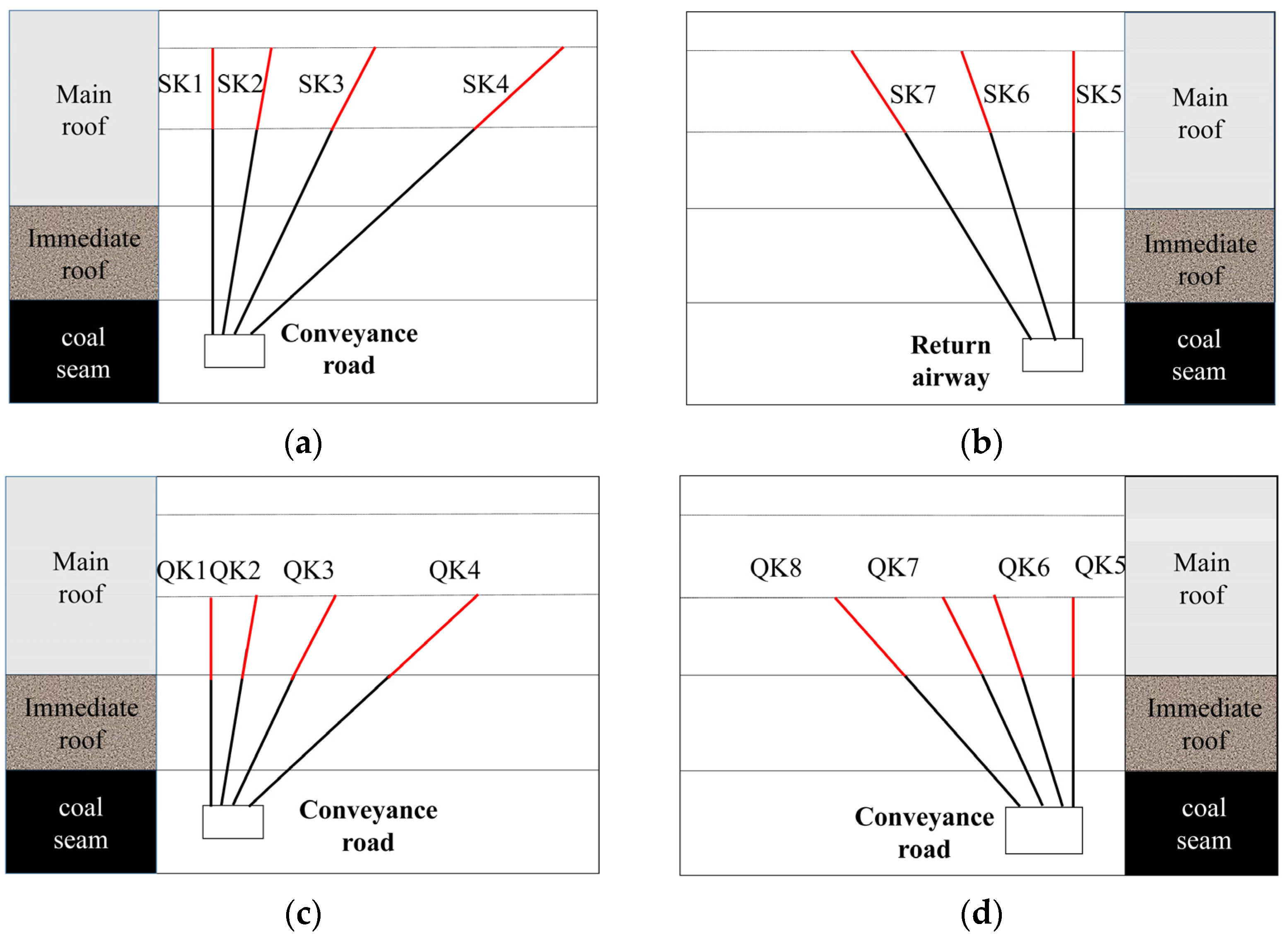
4.2. The Approach of Pre-Splitting at High Position and Shattering at Low Position

Based on actual geological and mining conditions, the following measures were implemented (Figure 10a,b): The construction area of pre-splitting at a higher position covered 20 m outward from the cutting hole to the stop lines. A group of blasting holes were arranged every 10 m, with four blasting holes in each group of conveyance roadways and three blasting holes in each group of return airways. As plotted in Figure 10c,d, the construction area of shattering at a lower position covered 20 m outward from the cutting hole to the stop lines. A group of blasting holes were arranged every 5 m in the conveyance roadways and return airways, with blasting four holes in each group. Specific parameters for pre-splitting blasting layout are shown in Table 4.

5. Analysis of Engineering Practices

5.1. Rock Burst Monitoring Results

By 23 December, 2018, a total of 4092 micro-seismic events with energy over 1000 J had been detected at the 207 working face, which included 306 micro-seismic events with energy between 104 J and 105 J, 40 micro-seismic events with energy between 105 J and 106 J and 2 micro-seismic events with energy about 106 J. Micro-seismic monitoring results are shown in Figure 11a,b.
Micro-seismic events with energy above 104 J were mainly distributed along the return airway from a horizontal aspect, which is close to goaf so that it was obviously affected by the superimposed stress. From the longitudinal aspects, micro-seismic events were mainly distributed at the multi-tunnel area and the synclinal axis position. Micro-seismic detection results show that several micro-seismic events reached above medium warning, and a series of measures were taken to remove the danger of rock burst at the warning area in time. In the end, there were early warnings of rock burst on the working face, but rock burst phenomena were not found, which effectively realized the prevention and control of a rock burst disaster.

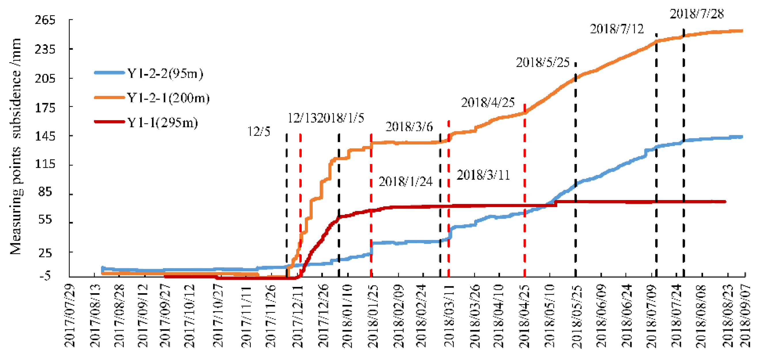
5.2. Cracking Height Measurement

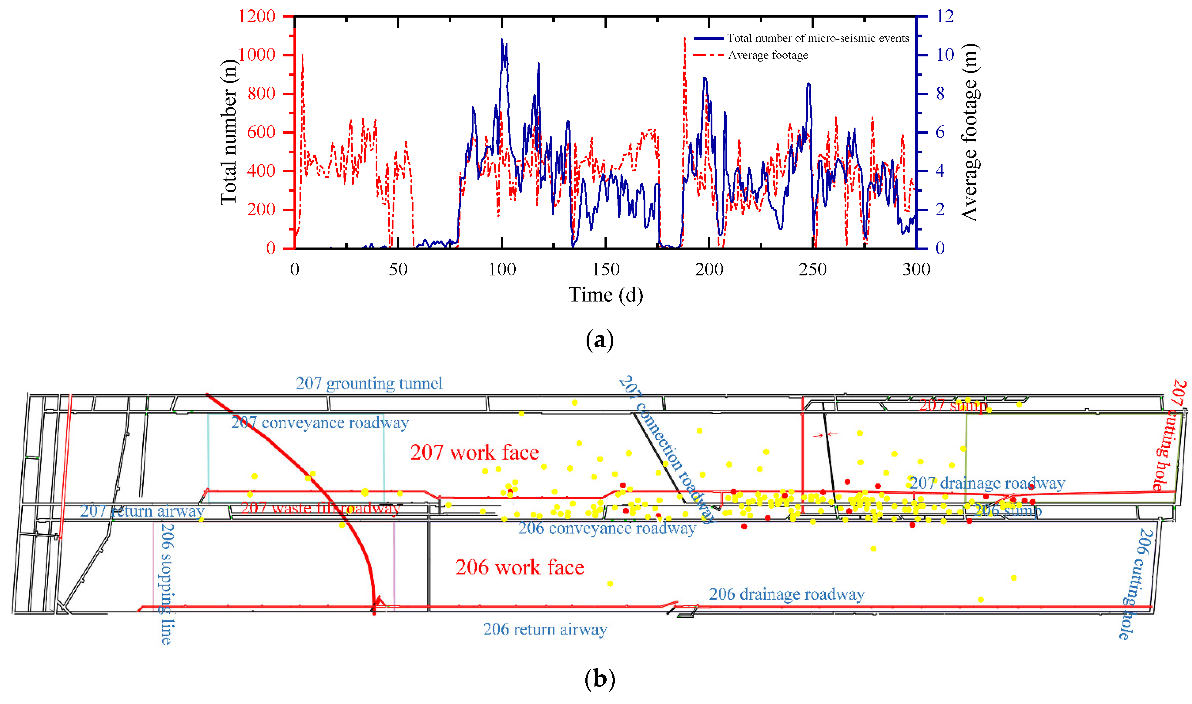
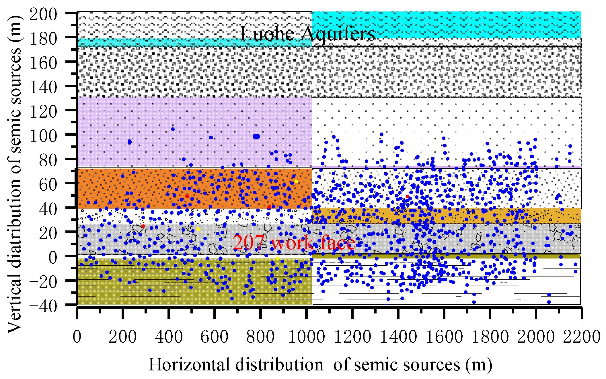
5.2.1. Analysis of Micro-Seismic Data

From August 2017 to January 2019, the source location of micro-seismic events above 1000 J at the 207 working face was projected according to their vertical position. As shown in Figure 12, micro-seismic events above 1000 J are mainly concentrated between 20 m below the tunnel floor and 120 m above the tunnel roof of the coal seam. The distribution height of micro-seismic events indicates the damage height of the overlying rock strata does not reach the Luohe aquifer (172 m). It can be concluded that mining activities did not form water channels and result in a water disaster control effect.

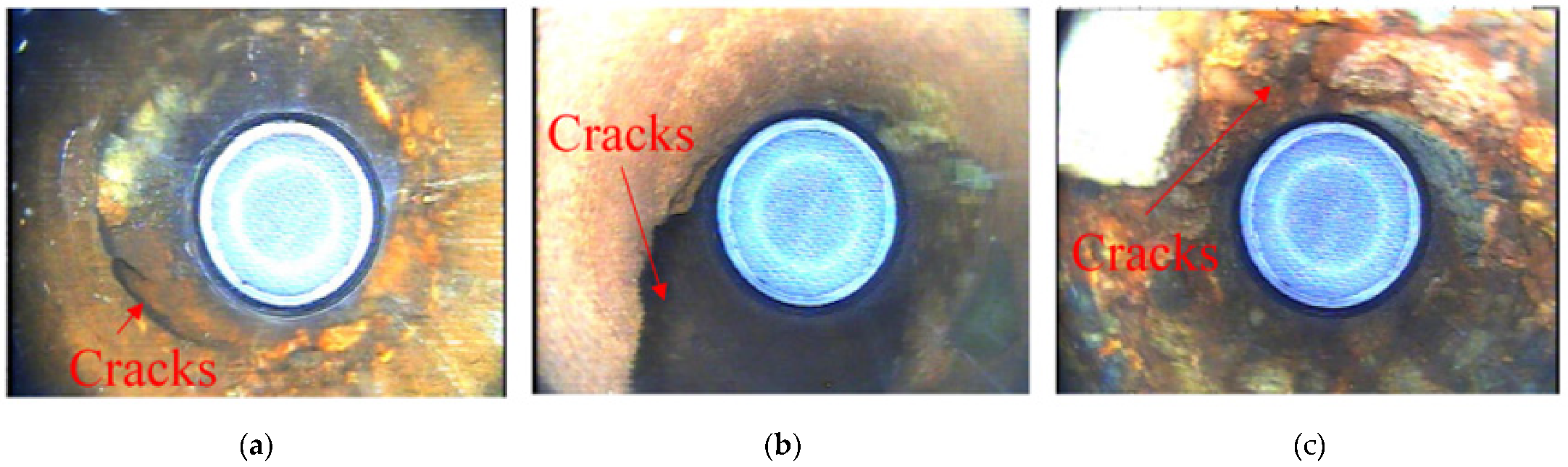
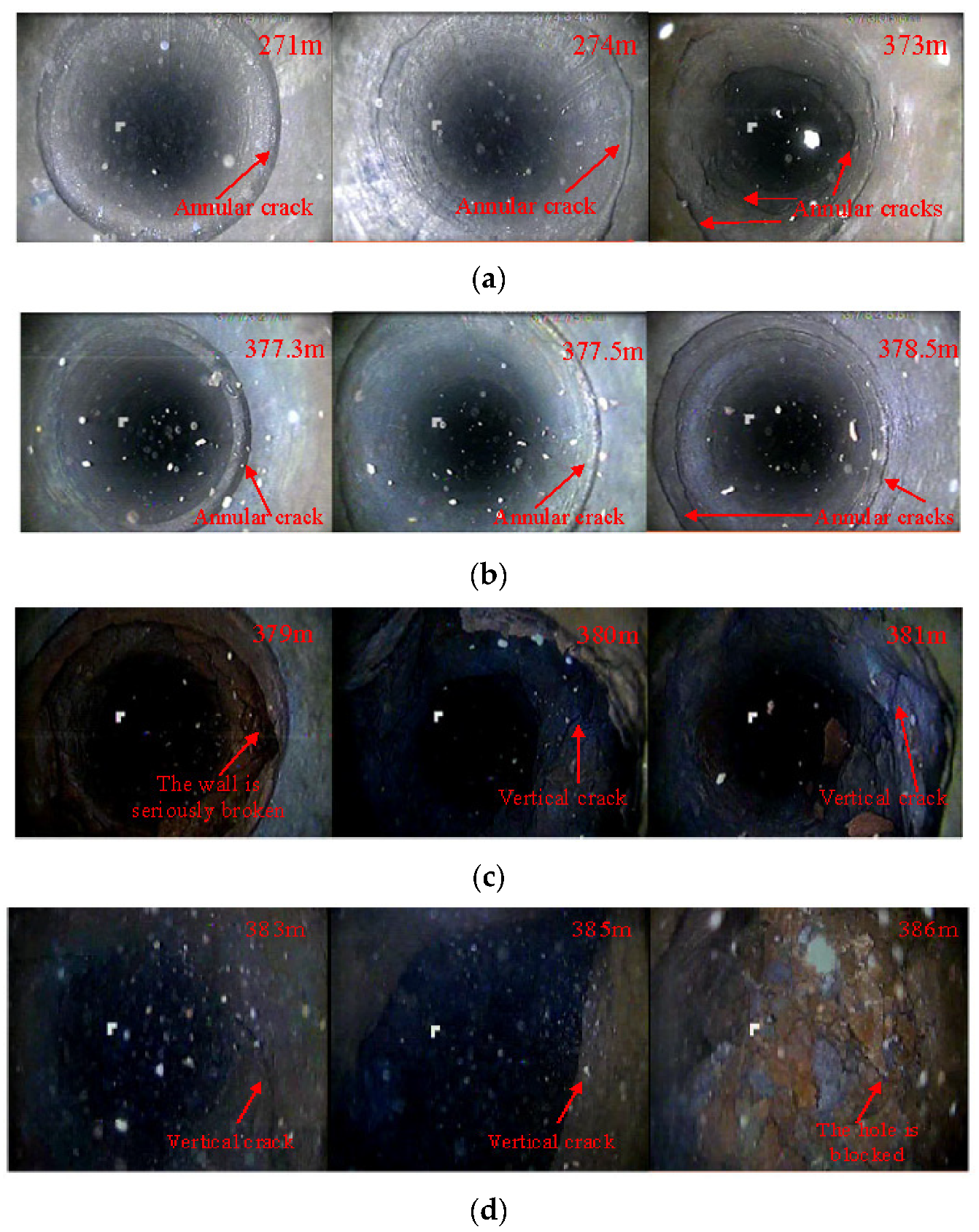
5.2.2. Analysis of Drilling Results

In order to further detect the damage height of overlying strata, three boreholes, namely Y1-1, Y1-2 and Y4, were drilled on the ground to detect the damage height. Among them, Y4 was applied to detect the height of the caving zone and the fracture zone; Y1-1 and Y1-2 were equipped with monitoring instruments to observe the rock strata movement of the Luohe aquifer in the process of mining at the 207 working face.
The position of Y4 was 891.723 m before mining, the elevation of the floor was 351 m, the buried depth of the roof was 522 m, and the thickness of the coal seam was 19 m. Some of the drilling results of Y4 are shown in Figure 13. Please see Figure 13a–d. One can see the annular cracks between 244–372 m. Below 373 m, the number of annular cracks at the hole wall obviously increased. Cracks in the hole wall at 377–379 m were continuously concentrated, and the hole wall at 379 m was seriously broken. At 380 m, obvious vertical cracks began to appear; at 386 m, the hole is blocked. Based on a comprehensive analysis, 379 m is determined to be the fracture top interface, the subsidence of the 207 working face is 1.3 m, and the crack height is 144.3 m.
As plotted in Figure 14, there are three monitoring instruments for strata movement, namely Y1-1, Y1-2-1 and Y1-2-2; their buried depth are 295 m, 200 m and 95 m, respectively. As of September 6, 2018, the working face was 931.1 m from Y1-1 and 928.1 m from Y1-2. As the working face was pushed away from the borehole, the movement of measuring points in the borehole slowed down, the ground subsidence gradually tended to be stable, and the monitoring data of rock movement basically remained stable. According to the borehole results of “two band”, the subsidence of the 207 working face is 1.3 m, and the crack height is 144.3 m; the ratio of crack height and mining height (9 m) is 16:1. This shows that there is no obvious crack in the sandstone of the Luohe aquifer, and the roof treatment can prevent water inrush at the same time.

6. Conclusions

(1)
A hard, thick roof is the key factor in the integrated prevention and control of multi-dynamic disasters in the Tingnan coal mine. The main contradiction for multi-dynamic disasters in a rock burst coal seam is that when the roof is treated to prevent rock burst, the risk of water inrush will be increased.
(2)
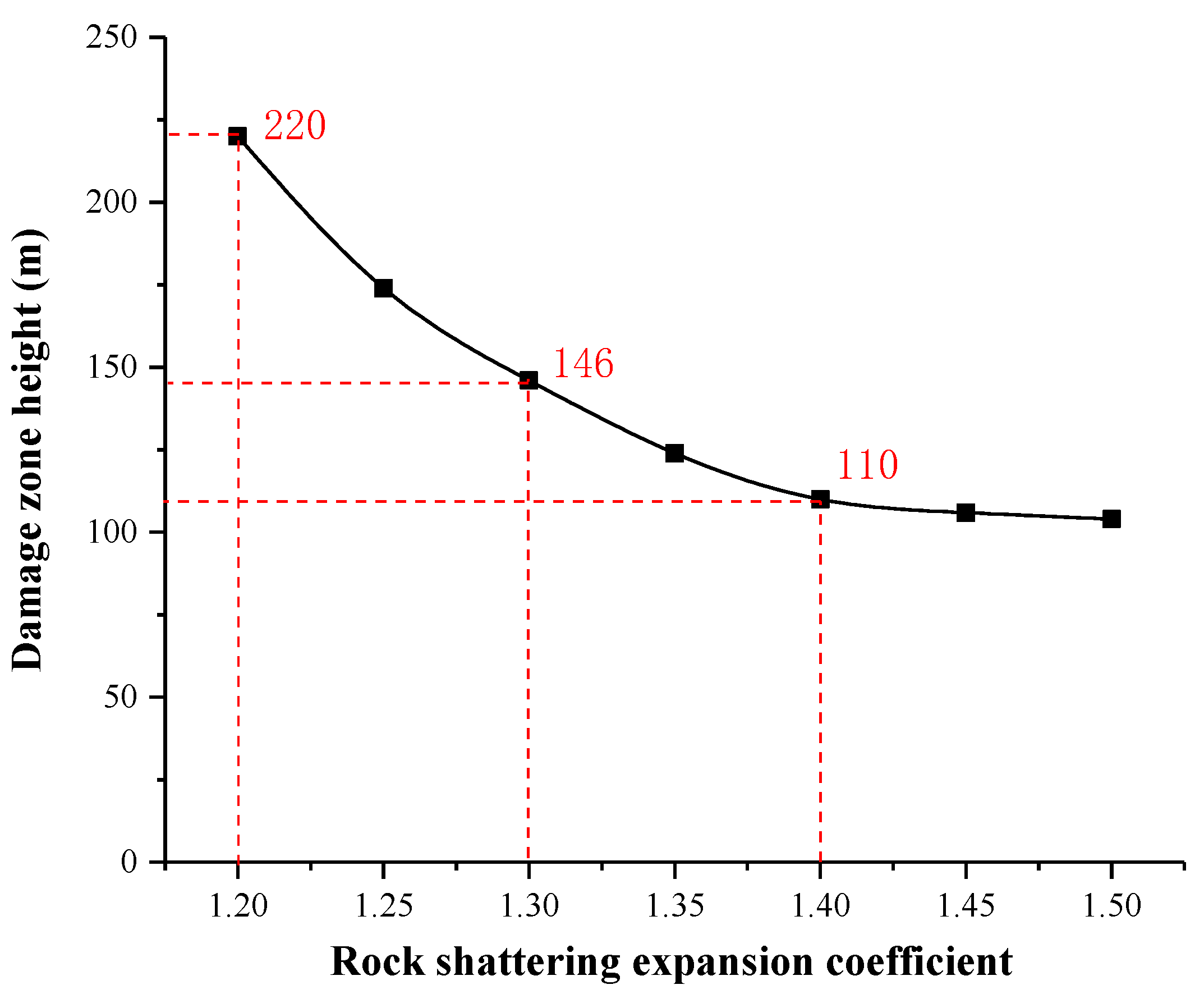
The proposed method is roof splitting at a high position and shattering at a low position, which can promote the roof caving in time and avoid the formation of a large area of hard suspended roof. At the same time, shattering at a low position helps increase the crushing degree of the rock, which is beneficial for decreasing the caving height of rock layers above the goaf, thereby attaining the desired effect.
(3)
Engineering practice has shown that the proposed method, pre-splitting at a high position and shattering at a low position, enables the prevention and control of the multi-dynamic disasters of rock burst and water inrush, which have a great significance to similar mines.
There are still some shortcomings in this paper. Limited by computer performance, only a two-dimensional numerical model was established, and the numerical simulation results are not accurate enough. In addition, this paper mainly used empirical formulas to calculate the height of the water-conducting fracture zone. In the next stage of research, we will further demonstrate the feasibility of this method by establishing more appropriate numerical and theoretical models.

Author Contributions

X.Z., R.Z. completed this paper, author Z.O. proposed the approach, pre-splitting at a higher position and shattering at a lower position, authors Z.J. and H.Y. checked and modified this paper, and authors Z.T., B.C., C.Y. and B.S. provided technical guidance. All authors have read and agreed to the published version of the manuscript.

Funding

The study presented in this paper was funded by the National Natural Science Foundation of China (Grant No.51974125, 52004090), the National Natural Science Foundation of Hebei Province (Grant No. E2020508002) and the Fundamental Research Funds for the Central Universities (No.3142018001, 3142019019). Acknowledgements are also given to the support of Tianchi Hundred People Program of Xinjiang Uygur Autonomous Region (2019(39)) herein.

Institutional Review Board Statement

Not applicable.

Informed Consent Statement

Not applicable.

Data Availability Statement

The data supporting the study are included in this paper.

Conflicts of Interest

Zhongyi Tang and Chengcheng Yang are employed by the Shaanxi Changwu Tingnan Coal Industry Co. Authors Bo Chang and Bingcheng Sun Shenhua are employed by the Xinjiang Energy Co. The remaining authors declare that the research was conducted in the absence of any commercial or financial relationships that could be construed as a potential conflict of interest.

References

  1. Keneti, A.; Sainsbury, B.A. Review of published rockburst events and their contributing factors. J. Eng. Geol. 2018, 246, 361–373. [Google Scholar] [CrossRef]
  2. Barton, N.; Shen, B. Risk of shear failure and extensional failure around over-stressed excavations in brittle rock. J. Rock Mech. Geotech. Eng. 2017, 9, 210–225. [Google Scholar] [CrossRef]
  3. Ma, T.H.; Tang, C.A.; Tang, L.X.; Zhang, W.D.; Wang, L. Rockburst characteristics and microseismic monitoring of deep-buried tunnels for Jinping II Hydropower Station. J. Tunn. Undergr. Space Technol. 2015, 49, 345–368. [Google Scholar] [CrossRef]
  4. Rehman, H.; Naji, A.M.; Nam, K.; Ahmad, S.; Muhammad, K.; Yoo, H.-K. Impact of construction method and ground composition on headrace tunnel stability in the Neelum–Jhelum Hydroelectric Project: A case study review from Pakistan. J. Appl. Sci. 2021, 11, 1655. [Google Scholar] [CrossRef]
  5. Shi, X.; Jiang, F.; Zhu, S.; Yang, G. Mechanism of integrated dynamic disaster of rockburst and water inrush: A new type of integrated dynamic disaster in China. J. Geotech. Geol. Eng. 2017, 35, 1261–1270. [Google Scholar] [CrossRef]
  6. An, Z.; Li, S.; Ding, Y. Study on mechanism of gas outburst caused by rock burst in deep mining. J. Coal Technol. 2015, 34, 127–129. [Google Scholar]
  7. Kaiser, P.K.; Cai, M. Design of rock support system under rockburst condition. J. Rock Mech. Geotech. Eng. 2012, 4, 215–227. [Google Scholar] [CrossRef] [Green Version]
  8. Adoko, A.C.; Gokceoglu, C.; Wu, L.; Zuo, Q.J. Knowledge-based and data-driven fuzzy modeling for rockburst prediction. Int. J. Rock Mech. Min. Sci. 2013, 61, 86–95. [Google Scholar] [CrossRef]
  9. Zhou, J.; Li, X.; Mitri, H.S. Evaluation method of rockburst: State-of-the-art literature review. J. Tunn. Undergr. Space Technol. 2018, 81, 632–659. [Google Scholar] [CrossRef]
  10. Xu, J.; Jiang, J.; Xu, N.; Liu, Q.; Gao, Y. A new energy index for evaluating the tendency of rockburst and its engineering application. J. Eng. Geol. 2017, 230, 46–54. [Google Scholar] [CrossRef]
  11. Pinzani, A.; Coli, N. A practical geostructural approach for the evaluation of tunnel water inflow by means of FEM seepage analysis. In Proceedings of the 45th US Rock Mechanics/Geomechanics Symposium, San Francisco, CA, USA, 26 June 2011. [Google Scholar]
  12. Bukowski, P. Water hazard assessment in active shafts in upper silesian coal basin mines. J. Mine Water Environ. 2011, 30, 302–311. [Google Scholar] [CrossRef] [Green Version]
  13. Li, S.; Zhou, Z.; Li, L.; Xu, Z.; Zhang, Q.; Shi, S. Risk assessment of water inrush in karst tunnels based on attribute synthetic evaluation system. J. Tunn. Undergr. Space Technol. 2013, 38, 50–58. [Google Scholar] [CrossRef]
  14. Odintsev, V.N.; Miletenko, N.A. Water inrush in mines as a consequence of spontaneous hydrofracture. J. Min. Sci. 2015, 51, 423–434. [Google Scholar] [CrossRef]
  15. Tan, Y.; Zhang, S.; Guo, W.; Liu, X. Mine stability and water inrush in coal mine. In Modelling Rock Fracturing Processes; Shen, B., Stephansson, O., Rinne, M., Eds.; Springer: Cham, Switzerland, 2020; pp. 361–403. [Google Scholar]
  16. Jiang, F.X.; Ye, G.X.; Wang, C.W.; Zhang, D.Y. Application of high-precision microseismic monitoring technique to water inrush monitoring in coal mine. Chin. J. Rock Mech. Eng. 2008, 27, 1932–1938. [Google Scholar]
  17. Wang, B.; Jiang, F.X.; Zhu, S.T.; Zhang, X.F.; Shang, X.G.; Gu, Y.S.; Wu, Z. Investigating on mechanism and prevention of rock burst induced by high intensity mining of drainage area in deep mines. J. China Coal Soc. 2020, 45, 3054–3064. [Google Scholar]
  18. Shu, C.; Jiang, F.; Wang, B.; Du, X.; Wen, J. Mechanism and treatment of rock burst on the deep working face induced by drainage in water-rich areas. J. Geotech. Geol. Eng. 2021, 39, 871–882. [Google Scholar] [CrossRef]
  19. Shi, L.Q.; Zhai, P.H.; Wei, J.C.; Zhu, L. Influencing action of water-inrush from roof on rockburst. J. China Coal Soc. 2009, 34, 44–49. [Google Scholar]
  20. Jing, J.-D.; Shi, L.-Q.; Li, Z.-L.; Liu, T.-B. Mechanism of water-inrush from roof in Huafeng mine. J. China Univ. Min. Technol. 2006, 35, 642–647. [Google Scholar]
  21. Li, D.; Jiang, F.; Wang, C.; Tian, Z. Study on the mechanism of rock burst induced by water inrush from deep. Chin. J. Rock Mech. Eng. 2018, 37, 4038–4046. [Google Scholar]
  22. Li, D.; Jiang, F.-X.; Chen, Y.; Shu, C.-X. Mechanism of rock burst induced by “dynamic-static” stress effect in water-rich working face of deep well. Chin. J. Geotech. Eng. 2018, 40, 1714–1722. [Google Scholar]
  23. Han, J.; Liang, B.; Zhang, H.W.; Zhu, Z. Tectonic stress environment of coal and rock dynamic hazard in Kailuan mining area. J. China Coal Soc. 2013, 38, 1154–1160. [Google Scholar]
  24. Ti, Z.Y.; Yang, L.I.; Qiao, N.; Qin, H.Y.; Chen, M.Y. Determining the roof fracture zone height based on the characteristic of the working face pressure. Chin. J. Geol. Hazard Control 2016, 27, 115–120. [Google Scholar]
  25. Xu, J.; Zhu, W.B.; Wang, X.Z. New method to predict the height of fractured water-conducting zone by location of key strata. J. China Coal Soc. 2012, 37, 762–769. [Google Scholar]
  26. Xu, J.L.; Wang, X.Z.; Liu, W.T.; Zang, Z.G. Influence of primary key stratum location on height of water flowing fracture zone. Chin. J. Rock Mech. Eng. 2009, 28, 381–385. [Google Scholar]
  27. Sheng, C.; Zhang, O.; Xu, D.X. Design of mine drainage system under condition of rock burst. J. Saf. Coal Mines 2018, 49, 171–174. [Google Scholar]
  28. He, H. Research on the evolution mechanism of spatial structure of overlying strata and rock burst inducing in coal mine. J. China Coal Soc. 2012, 37, 1245–1246. [Google Scholar]
  29. Feng, X.; Wang, E.; Shen, R.; Wei, M. The dynamic impact of rock burst induced by the fracture of the thick and hard key stratum. Procedia Eng. 2011, 26, 457–465. [Google Scholar]
  30. Yang, Z.; Liu, C.; Zhu, H.; Xie, F. Mechanism of rock burst caused by fracture of key strata during irregular working face mining and its prevention methods. Int. J. Min. Sci. Technol. 2019, 29, 889–897. [Google Scholar] [CrossRef]
  31. He, H.; Dou, L.-M.; Gong, S.; Zhou, P. Rock burst rules induced by cracking of overlying key stratum. Chin. J. Geotech. Eng. 2010, 32, 1260–1265. [Google Scholar]
  32. Dou, L.; He, X.-Q.; He, H.; He, J. Spatial structure evolution of overlying strata and inducing mechanism of rockburst in coal mine. Trans. Nonferrous Met. Soc. China 2014, 24, 1255–1261. [Google Scholar] [CrossRef]
  33. Wang, F.; Xu, J.; Chen, S.; Ren, M. Method to predict the height of the water conducting fractured zone based on bearing structures in the overlying strata. J. Mine Water Environ. 2019, 38, 767–779. [Google Scholar] [CrossRef]
  34. Zhao, Z.; Liu, J.; Wang, L.; Zong, C. Prediction and actual measurement of water flowing fractured zone height in overburden strata of flat seam. J. Min. Saf. Environ. Prot. 2017, 44, 66–69. [Google Scholar]
  35. Guo, W.; Zhao, G.; Lou, G.; Wang, S. A new method of predicting the height of the fractured water-conducting zone due to high-intensity longwall coal mining in China. Rock Mech. Rock Eng. 2019, 52, 2789–2802. [Google Scholar] [CrossRef]
  36. Xie, X.; Hou, E.; Wang, S.; Sun, X.; Hou, P.; Wang, S.; Xie, Y.; Huang, Y. Formation mechanism and the height of the water-conducting fractured zone induced by middle deep coal seam mining in a sandy region: A case study from the Xiaobaodang coal mine. Adv. Civ. Eng. 2021, 2021, 1–11. [Google Scholar]
  37. State Coal Industry Administration. Specification for Coal Pillar Reservation and Coal Pressure Mining of Buildings, Water Bodies, Railways and Main Shafts and Roadways; China Coal Industry Publishing House: Beijing, China, 2000. [Google Scholar]
  38. Qi, Q.-X.; Lei, Y.; Li, H.-Y.; Ji, Z.-W. Theory and application of prevention of rock burst by break-tip blast in deep hole. Chin. J. Rock Mech. Eng. 2007, 26, 3522–3527. [Google Scholar]
  39. Li, W.; Cheng, J.; Wang, Y.; Qi, M. Study on the technology of rock-burst prevention and control by using advanced break-tip blast. China Min. Mag. 2008, 17, 95–97. [Google Scholar]
  40. Shugang, L.; Lijie, X.; Chao, L. Application of deep hole break-tip blasting technology in hard roof depressurization. Saf. Coal Mines 2015, 46, 128–131. [Google Scholar]
  41. Xu, J. Study and application of dominant stratum theory for control of strata movement. China Min. Mag. 2001, 6, 56–58. [Google Scholar]
  42. Hao, J.; Shi, Y.; Lin, J.; Wang, X.; Xia, H. The effects of backfill mining on strata movement rule and water inrush: A case study. Processes 2019, 7, 66. [Google Scholar] [CrossRef] [Green Version]
  43. Cheng, G.; Chen, C.; Li, L.; Zhu, W.; Yang, T.; Dai, F.; Ren, B. Numerical modelling of strata movement at footwall induced by underground mining. Int. J. Rock Mech. Min. Sci. 2018, 108, 142–156. [Google Scholar] [CrossRef]
  44. Li, M.; Zhang, J.; Zhou, N.; Huang, Y. Effect of particle size on the energy evolution of crushed waste rock in coal mines. J. Rock Mech. Rock Eng. 2016, 50, 1347–1354. [Google Scholar] [CrossRef]
  45. Li, M.; Zhang, J.; Song, W.; Germain, D.M. Recycling of crushed waste rock as backfilling material in coal mine: Effects of particle size on compaction behaviours. Environ. Sci. Pollut. Res. 2019, 26, 8789–8797. [Google Scholar] [CrossRef]
  46. Guo, C.-Y.; Xian, X.-F.; Wu, X.-H.; Yao, W.-J. The relationship among rock crushing energy, the Protodyakonov coefficient and rock strength. J. Chongqing Jianzhu Univ. 2008, 30, 28–31. [Google Scholar]
Figure 1. The location of Tingnan coal mine.
Energies 14 07287 g001
Figure 2. The diagrammatic sketch of working faces at the No. 2 panel area.
Energies 14 07287 g002
Figure 3. Damage situation at the No. 2 panel area. (a,b) support failure at roadway walls.
Energies 14 07287 g003
Figure 4. The results of D2 drilling TV images. (a) Depth: 119.60 m, (b) depth: 386.90 m, (c) depth: 392.59 m.
Energies 14 07287 g004
Figure 5. The change rules of damage zone height with rock-shattering expansion coefficient.
Energies 14 07287 g005
Figure 6. Numerical model diagrams. (a) The whole model, (b) local amplified details.
Energies 14 07287 g006
Figure 7. Roof caving process by conventional mining at the length of (a) 60 m and (b) 70 m, respectively.
Energies 14 07287 g007
Figure 8. Roof caving process by pre-splitting at overlying strata at the mining length of (a) 50 m and (b) 100 m, respectively.
Energies 14 07287 g008
Figure 9. Roof caving process by pre-splitting at high position and shattering at underlying position at the mining length of (a) 50 m and (b) 100 m, respectively.
Energies 14 07287 g009
Figure 10. The schematic diagram of pre-splitting blasting at high position and shattering at low position. (a) Conveyance road, (b) return airway, (c) conveyance road, (d) return airway.
Energies 14 07287 g010
Figure 11. Micro-seismic monitoring data at 207 working face. (a) The number of micro-seismic events varies with daily footage, (b) source location distribution of micro-seismic events.
Energies 14 07287 g011
Figure 12. Vertical distribution of micro-seismic events.
Energies 14 07287 g012
Figure 13. The diagram in Y4 borehole. (a) The damage from 271 m to 373 m, (b) the damage from 377.3 m to 378.5 m, (c) the damage from 379 m to 381 m, (d) the damage from 383 m to 386 m.
Energies 14 07287 g013
Figure 14. The rock movement in the borehole above goaf at 207 working face.
Energies 14 07287 g014
Table 1. Water inflow at the No. 2 panel area.
Working FaceMining Height (m)Normal Water Inflow (m3·h−1)Maximum Water Inflow (m3·h−1)
2011000
2046150–250270
2056150–250504
2069240–380490
Table 2. Lithological characteristics at the No. 2 panel area investigated by borehole.
No. LithologyAverage
Thickness (m)
Average
Depth (m)
Key Stratum
1 Energies 14 07287 i001Fine sandstone17.1217.62
2 Energies 14 07287 i002Medium sandstone2138.62
3 Energies 14 07287 i003Cobble conglomerate60.3899Main key stratum
4 Energies 14 07287 i004Coarse sandstone52.7151.70
5 Energies 14 07287 i005Siltstone1.8153.50
6 Energies 14 07287 i006Coarse sandstone59.31212.81
7 Energies 14 07287 i007Mudstone1.7214.51
8 Energies 14 07287 i008Medium sandstone0.99215.50
9 Energies 14 07287 i009Coarse sandstone2217.50
10 Energies 14 07287 i010Medium sandstone66283.50Inferior key strata
11 Energies 14 07287 i011Fine sandstone25.1308.60
12 Energies 14 07287 i012Granite31.4340.00Inferior key strata
13 Energies 14 07287 i013Fine sandstone17357.00
14 Energies 14 07287 i014Mudstone21.3378.30
15 Energies 14 07287 i015Coarse sandstone12.7391.00
16 Energies 14 07287 i016Mudstone7.4398.40
17 Energies 14 07287 i017Coarse sandstone17.1415.50
18 Energies 14 07287 i018Mudstone14.2429.70
19 Energies 14 07287 i019Coarse sandstone2.5432.20
20 Energies 14 07287 i020Mudstone14446.20
21 Energies 14 07287 i021Coarse sandstone2.7448.90
22 Energies 14 07287 i022Mudstone3.5452.40
23 Energies 14 07287 i023No.3 coal seam0.1452.50
24 Energies 14 07287 i024Mudstone34.9487.40Inferior key strata
25 Energies 14 07287 i025No.4 coal seam21.37508.77
Table 3. Physical and mechanical parameters for modelling.
Rock LayerDensity (kg·m−3)Elastic Modulus (MPa)Poisson Ratio (-)Cohesion (MPa)Friction Angle (°)Tensile Strength (MPa)
Coarse sandstone253040900.216.5739.24.21
Medium sandstone258059900.24.0371.2
Mudstone257012500.223.4337.412.28
Sandy mudstone251054250.1472.16360.75
Sandy conglomerate272152000.255.237.62.81
Coal13355300.252.2136.290.64
Table 4. Parameters for pre-splitting blasting layout.
BoreholeElevated Angle (°)Azimuth Angle (°)Length
(m)
Aperture
(mm)
Charge Length (m)Charge
Weight (kg)
Sealing Length
(m)
SK19004075103030
SK275304175103131
SK3553304975123637
SK43507075175252
SK59004075103030
SK675304175103131
SK7603304675123435
QK19003075123518
QK275303175123719
QK3553303775154322
QK43505275216231
QK59003075123518
QK675303175123719
QK7603303575144121
QK83505275216231
Publisher’s Note: MDPI stays neutral with regard to jurisdictional claims in published maps and institutional affiliations.

