
Automatic Clutch Engagement Control for Parallel Hybrid Electric Vehicle


Abstract
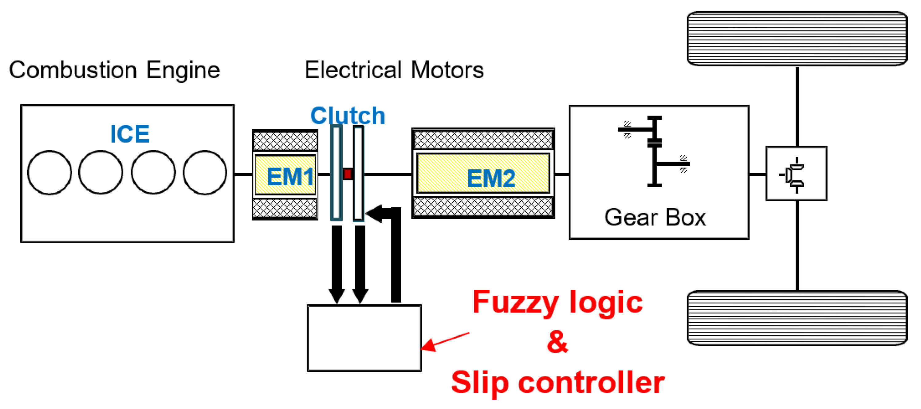
:1. Introduction
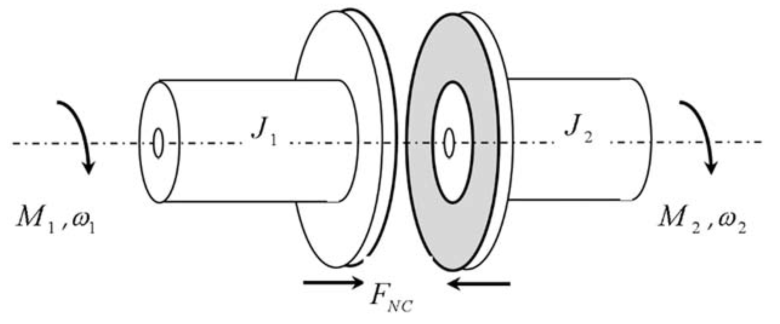
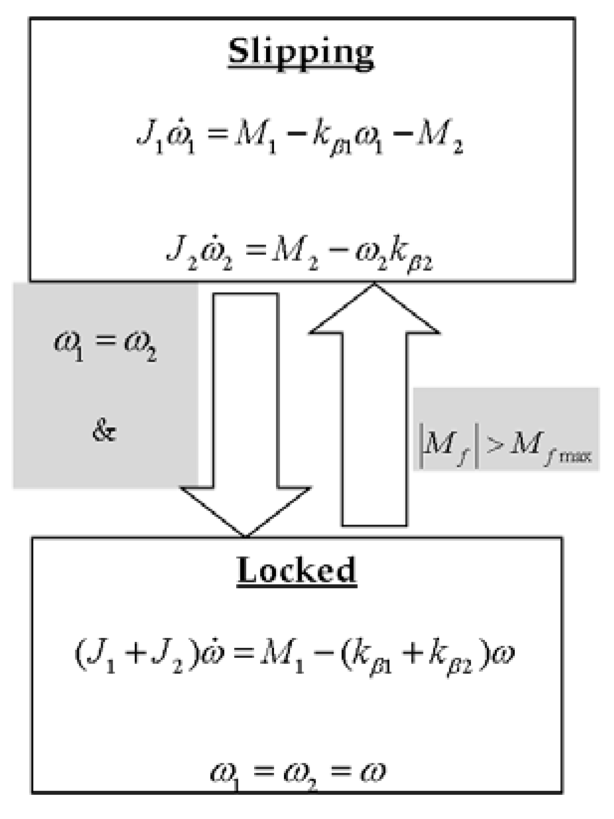
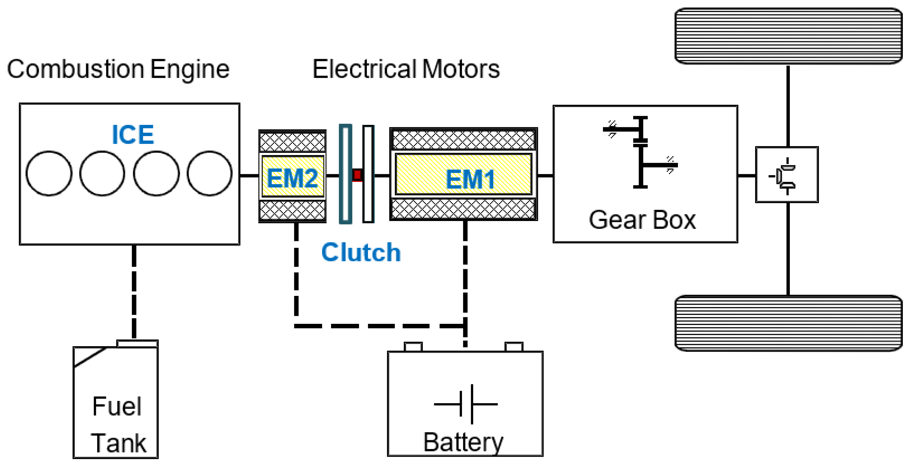
2. Modelling of Clutch Engagement
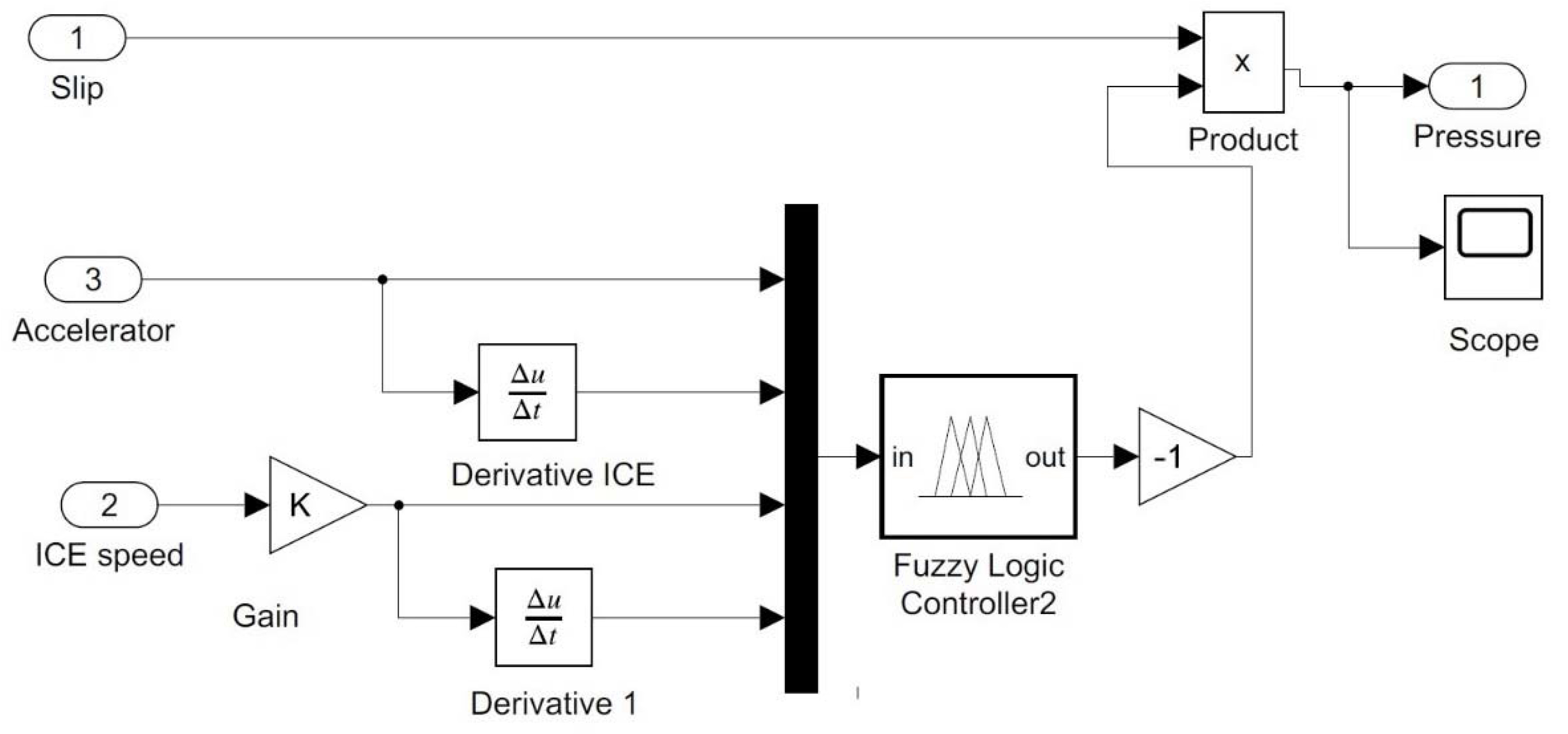
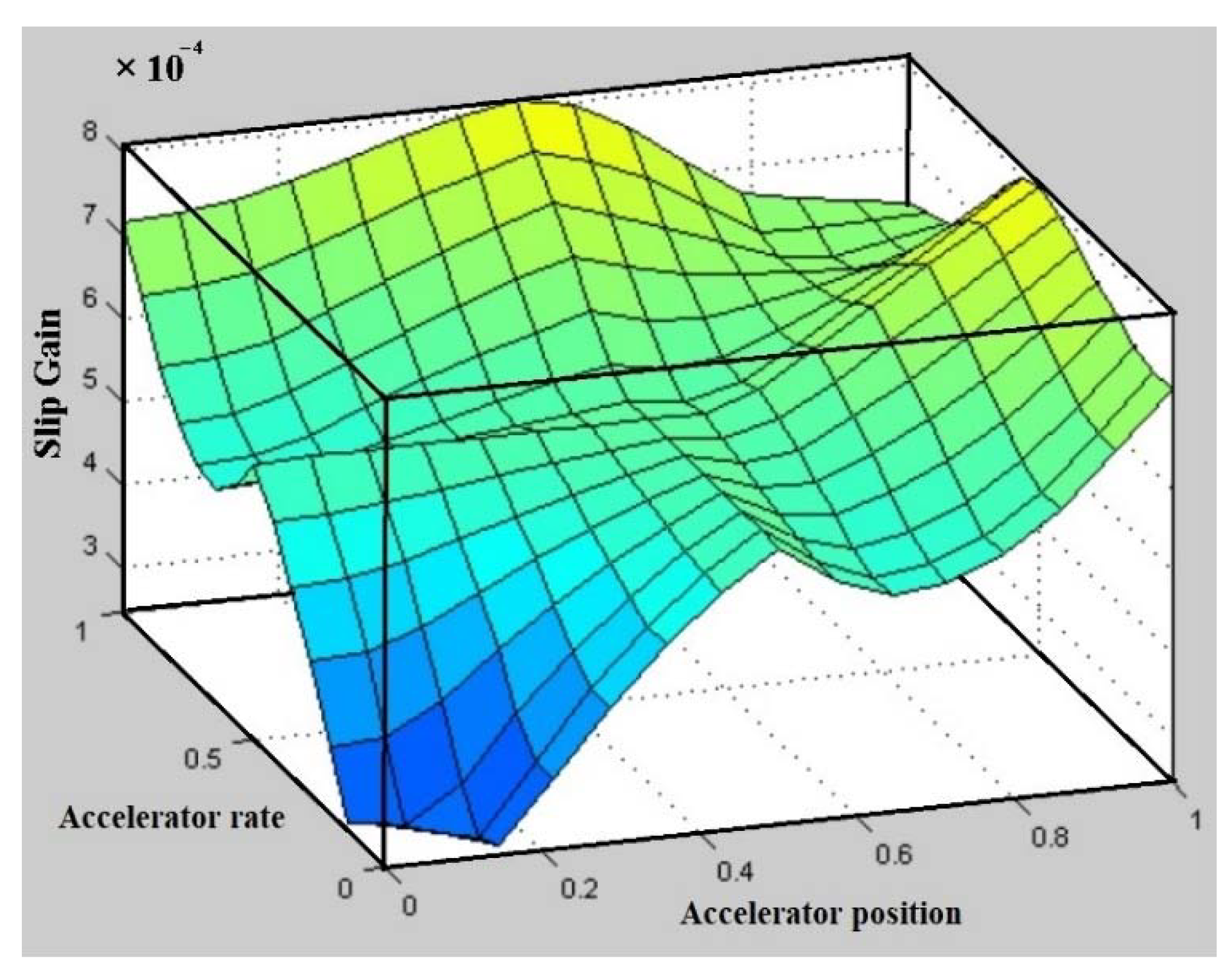
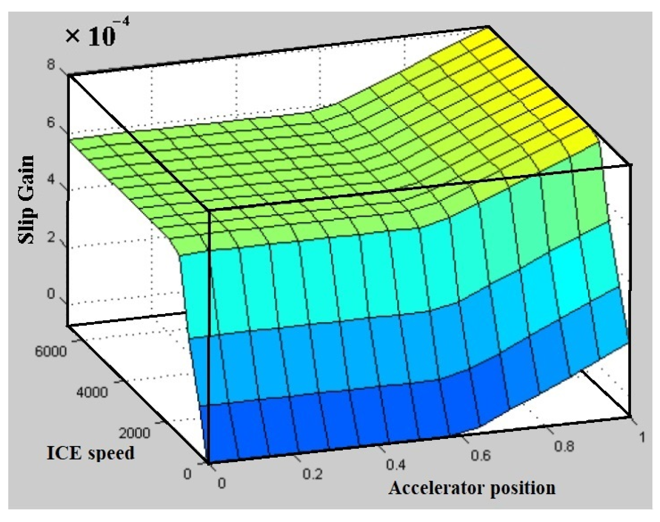
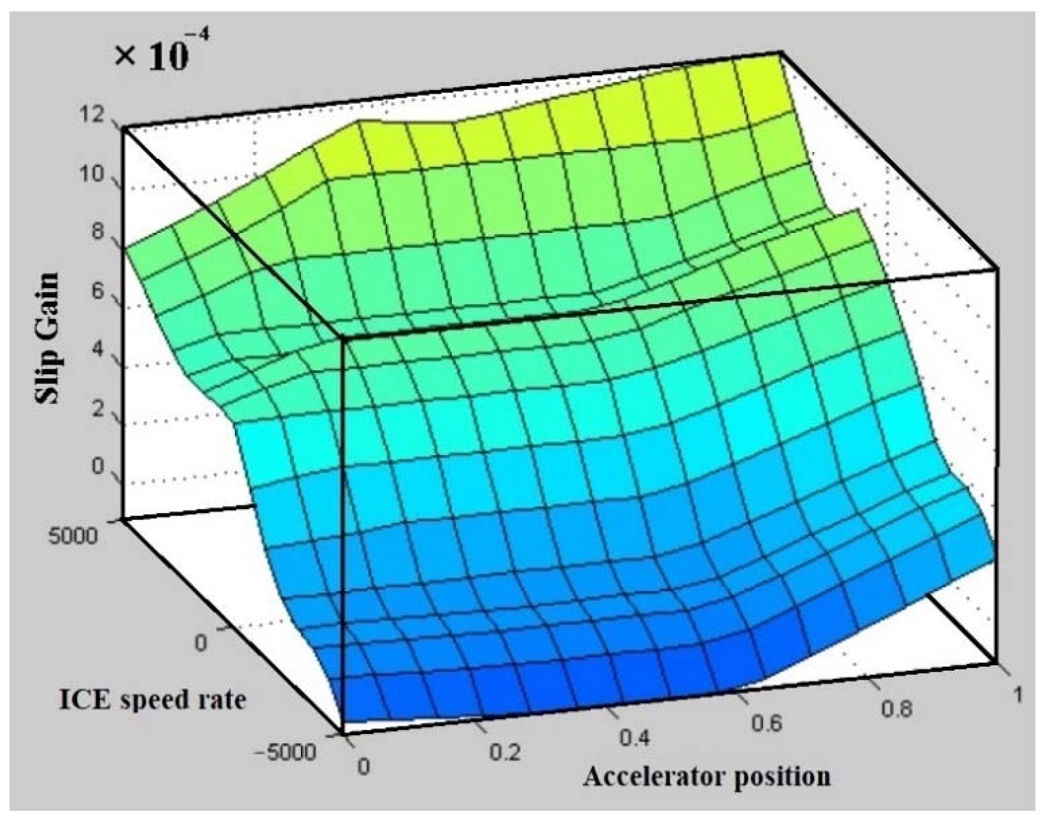
3. Fuzzy Logic Controller Design
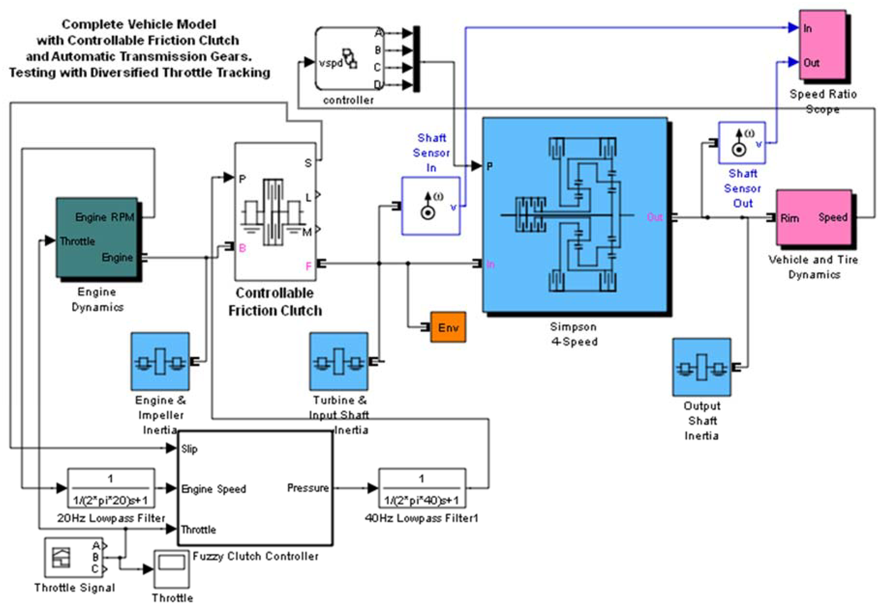
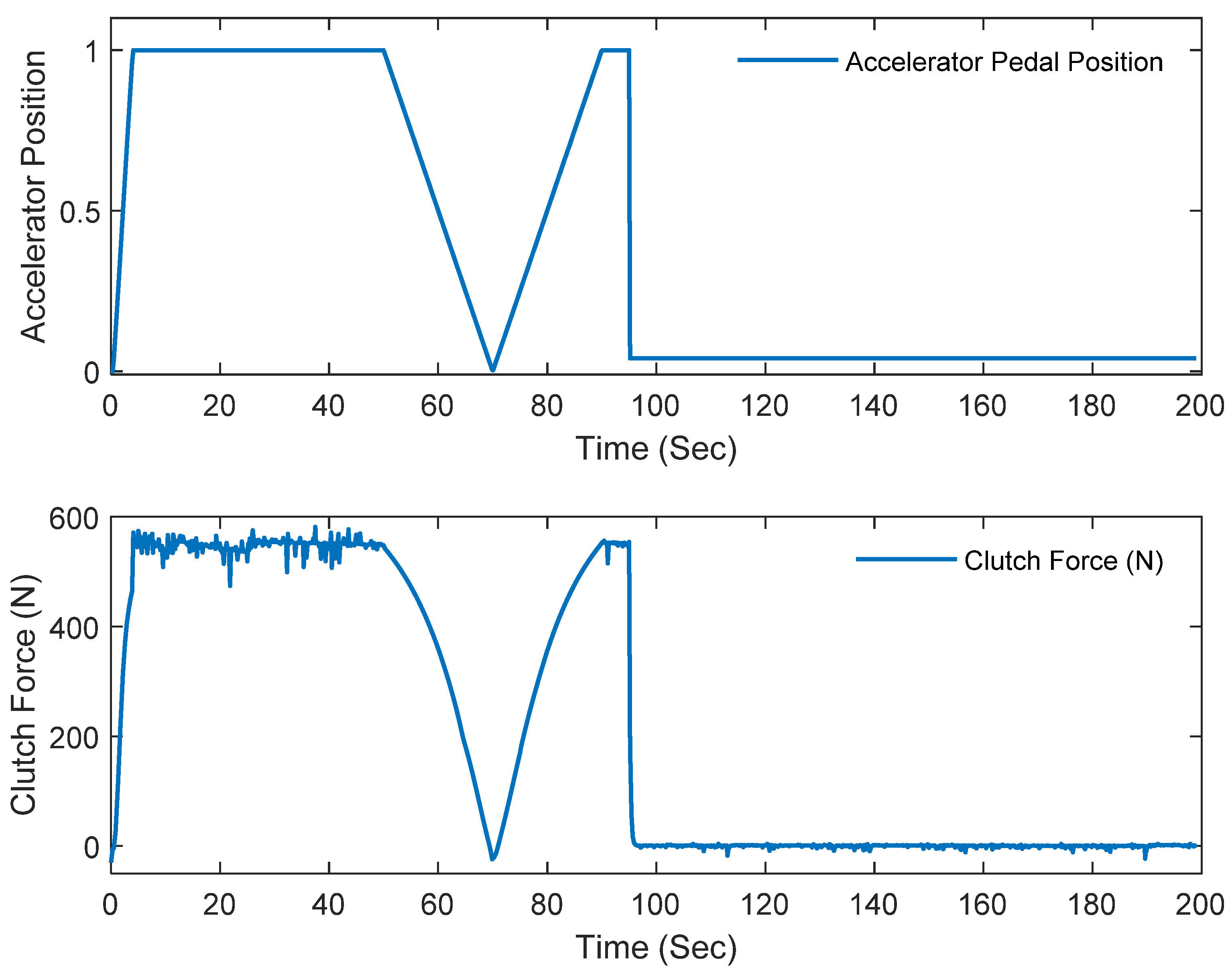
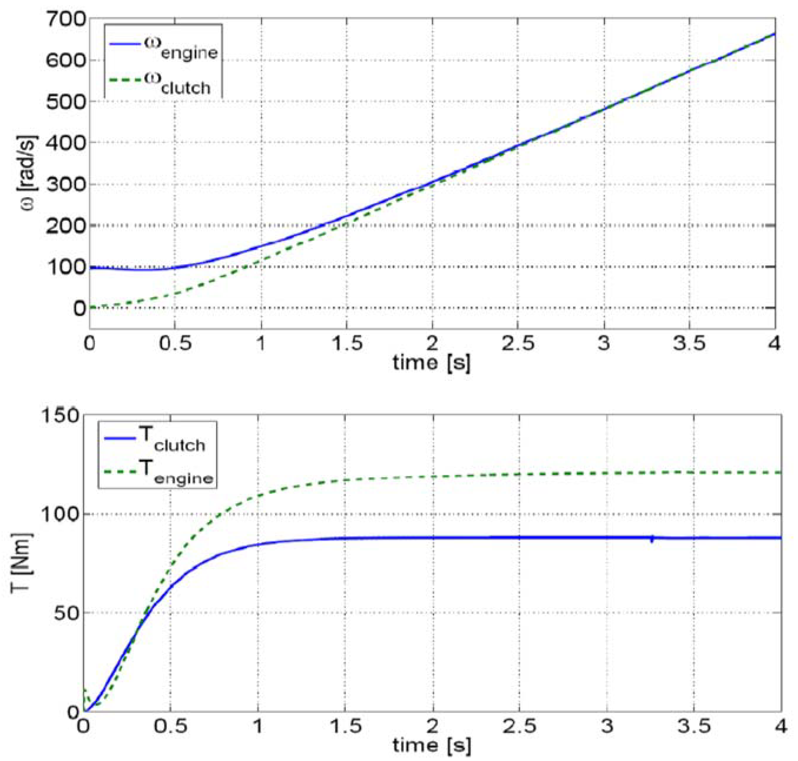
4. Simulink Simulations
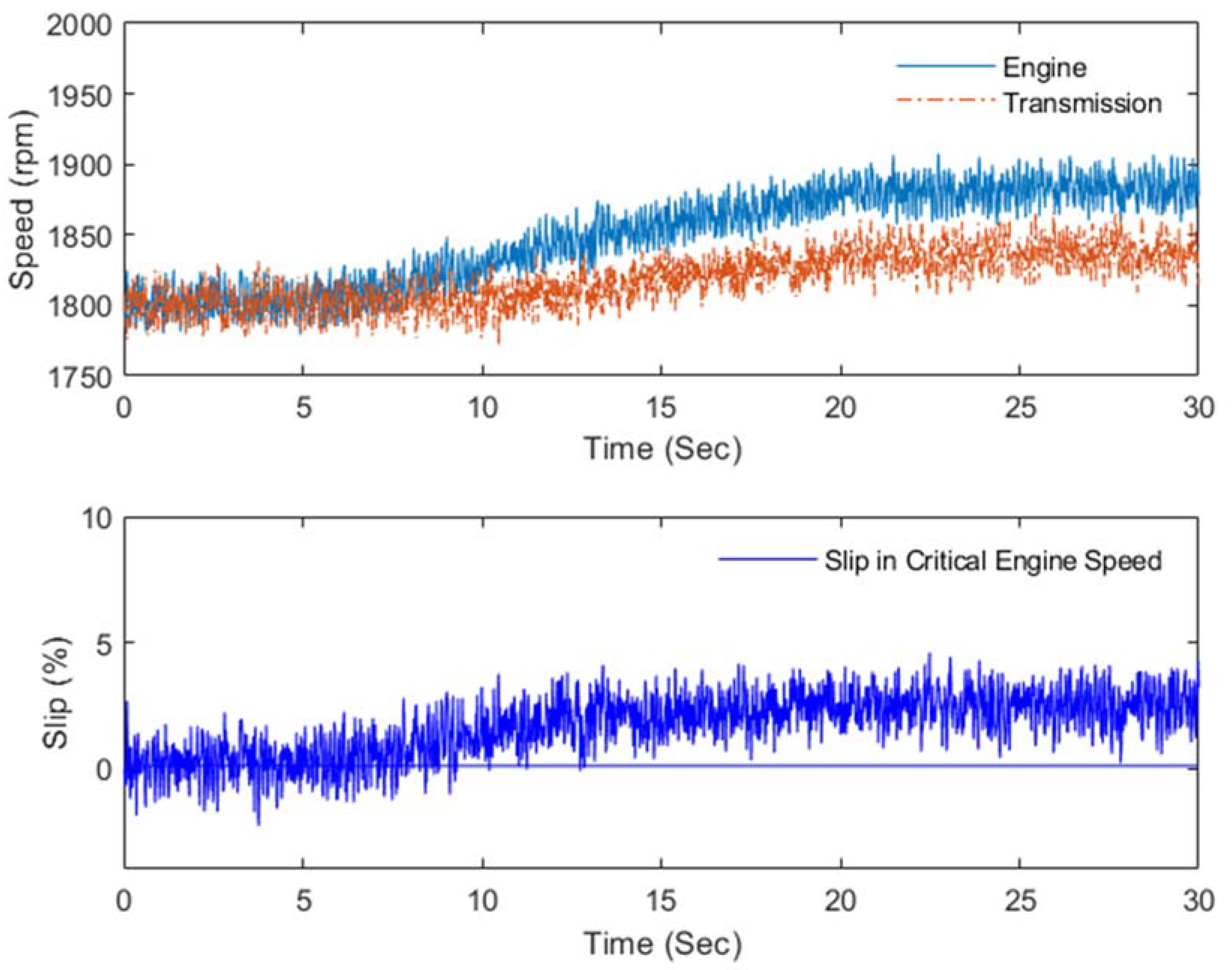
5. Experiments
6. Conclusions
Author Contributions
Funding
Institutional Review Board Statement
Informed Consent Statement
Data Availability Statement
Conflicts of Interest
References
- Tamada, S.; Bhattacharjee, D.; Dan, P.K. Review on automatic transmission control in electric and non-electric automotive powertrain. Int. J. Veh. Perform. 2020, 6, 98–128. [Google Scholar] [CrossRef]
- Singh, K.V.; Bansal, H.O.; Singh, D. A comprehensive review on hybrid electric vehicles: Architectures and components. J. Mod. Transport. 2019, 27, 77–107. [Google Scholar] [CrossRef] [Green Version]
- Yang, C.; Zha, M.; Wang, W.; Liu, K.; Xiang, C. Efficient energy management strategy for hybrid electric vehicles/plug-in hybrid electric vehicles: Review and recent advances under intelligent transportation system. IET Intell. Transp. Syst. 2020, 14, 702–711. [Google Scholar] [CrossRef]
- Tung, S.C.; Woydt, M.; Shah, R. Global Insights on Future Trends of Hybrid/EV Driveline Lubrication and Thermal Management. Front. Mech. Eng. 2020, 6, 74. [Google Scholar] [CrossRef]
- Shi, T.; Zhao, F.; Hao, H.; Liu, Z. Development Trends of Transmissions for Hybrid Electric Vehicles Using an Optimized Energy Management Strategy. Automot. Innov. 2018, 1, 291–299. [Google Scholar] [CrossRef] [Green Version]
- Galvagno, E.; Guercioni, G.; Rizzoni, G.; Velardocchia, M.; Vigliani, A. Effect of engine start and clutch slip losses on the energy management problem of a hybrid DCT powertrain. Int. J. Automot. Technol. 2020, 21, 953–969. [Google Scholar] [CrossRef]
- Zhao, Q.; Zhang, H.; Xin, Y. Research on Control Strategy of Hydraulic Regenerative Braking of Electrohydraulic Hybrid Electric Vehicles. Math. Probl. Eng. 2021, 2021. [Google Scholar] [CrossRef]
- Xu, Q.; Wang, F.; Zhang, X.; Cui, S. Research on the Efficiency Optimization Control of the Regenerative Braking System of Hybrid Electrical Vehicle Based on Electrical Variable Transmission. IEEE Access 2019, 7, 116823–116834. [Google Scholar] [CrossRef]
- Yao, Z.; Yoon, H.S. Control Strategy for Hybrid Electric Vehicle Based on Online Driving Pattern Classification. SAE Int. J. Alt. Power 2019, 8, 91–102. [Google Scholar] [CrossRef]
- Sim, K.; Oh, S.M.; Namkoong, C.; Lee, J.S.; Han, K.S.; Hwang, S.H. Control Strategy of Clutch Engagement during Mode Change of Plug-in Hybrid Electric Vehicle. Int. J. Automot. Technol. 2017, 18, 901–909. [Google Scholar] [CrossRef]
- Wang, S.; Xia, B.; He, C.; Zhang, S.; Shi, D. Mode transition control for single-shaft parallel hybrid electric vehicle using model predictive control approach. Adv. Mech. Eng. 2018, 10, 1–10. [Google Scholar] [CrossRef] [Green Version]
- Robuschi, N.; Zeile, C.; Sager, S.; Braghin, F. Multiphase mixed-integer nonlinear optimal control of hybrid electric vehicles. Automatica 2021, 123, 109325. [Google Scholar] [CrossRef]
- Wróblewski, P.; Kupiec, J.; Drozdz, W.; Lewicki, W.; Jaworski, J. The Economic Aspect of Using Different Plug-In Hybrid Driving Techniques in Urban Conditions. Energies 2021, 14, 3543. [Google Scholar] [CrossRef]
- He, R.; Yan, Y.; Hu, D. Optimised adaptive control methodology for mode transition of hybrid electric vehicle based on the dynamic characteristics analysis. Veh. Syst. Dyn. 2021, 59, 1282–1303. [Google Scholar] [CrossRef]
- Elzaghir, W.; Zhang, Y.; Natarajan, N.; Massey, F.; Mi, C. Control of a hybrid electric vehicle with dual clutch transmission configurations during mode transition. Int. J. Electr. Hybrid Veh. 2018, 10, 1–25. [Google Scholar] [CrossRef]
- Kim, S.; Choi, S.B. Cooperative Control of Drive Motor and Clutch for Gear Shift of Hybrid Electric Vehicles with Dual-Clutch Transmission. ASME Trans. Mechatron. 2020, 25, 1578–1588. [Google Scholar] [CrossRef]
- Ning, J.; Zhu, G.; Qu, B. Development of a engine start control method for P2 hybrid vehicles in launch situation. IFAC PapersOnLine 2018, 51, 7–10. [Google Scholar] [CrossRef]
- Huang, W.; Zhang, J.; Huang, J.; Yin, C.; Wang, L. Optimal Speed Regulation Control of the Hybrid Dual Clutch Transmission Shift Process. World Electr. Veh. J. 2020, 11, 11. [Google Scholar] [CrossRef] [Green Version]
- Cao, X.; Du, C.; Yan, F.; Xu, H.; He, B.; Sui, Y. Parameter Optimization of Dual Clutch Transmission for an Axle-split Hybrid Electric Vehicle. IFAC PapersOnLine 2019, 52, 423–430. [Google Scholar] [CrossRef]
- Wang, S.; Liu, Y.; Cai, T. Clutch Control Strategy of Driving Mode Transition for P2 Hybrid Electric Vehicle. IOP Conf. Ser. Mater. Sci. Eng. 2019, 470, 012003. [Google Scholar] [CrossRef]
- Zhang, H.; Zhao, X.; Yang, J.; Yang, W. Shift Strategy Optimization for Automatic Transmission of Heavy Trucks Based on Dynamic Programming Algorithm. Appl. Sci. 2021, 11, 5555. [Google Scholar] [CrossRef]
- Ding, J.; Jiao, X. A Novel Control Method of Clutch During Mode Transition of Single-Shaft Parallel Hybrid Electric Vehicles. Electronics 2020, 9, 54. [Google Scholar] [CrossRef] [Green Version]
- Bang, J.S.; Choi, S.H.; Ko, Y.K.; Kim, T.S.; Kim, S. The Engine Clutch Engagement Control for Hybrid Electric Vehicles. In Proceedings of the 2018 IEEE Conference on Control Technology and Applications (CCTA), Copenhagen, Denmark, 21–24 August 2018; pp. 1448–1453. [Google Scholar]
- Song, M.; Wang1, H.; Liu, H.; Peng, P.; Wang, X.; Pi, D.; Yang, C.; He, G. Double-layer Control of an Automatic Mechanical Transmission Clutch during Commercial Vehicle Start-up. J. Mech. Eng. 2019, 65, 515–524. [Google Scholar] [CrossRef]
- Liu, Y.; Xie, J.; Qin, D.; Zhang, Y.; Chen, Z.; Li, G.; Zhang, Y. Design, Control and Validation of Two-Speed Clutch-less Automatic Transmission for Electric Vehicle. IEEE/ASME Trans. Mechatron. 2021, 1–11. [Google Scholar]
- Minh, V.T.; Pumwa, J. Feasible Path Planning for Autonomous Vehicles. Math. Probl. Eng. 2014, 2014. [Google Scholar] [CrossRef]
- Minh, V.T.; Mohd Hashim, F.B.; Awang, M. Development of a real-time clutch transition strategy for a parallel hybrid electric vehicle. Proc. Inst. Mech. Eng. Part I J. Syst. Control. Eng. 2012, 226, 188–203. [Google Scholar] [CrossRef]
- Minh, V.T.; Afzulpurkar, N.; Muhamad, W.W. Fault detection model-based controller for process systems. Asian J. Control. 2011, 13, 382–397. [Google Scholar] [CrossRef]
- Minh, V.T.; Hashim, F.B.M. Tracking setpoint robust model predictive control for input saturated and softened state constraints. Int. J. Control. Autom. Syst. 2011, 9, 958–965. [Google Scholar] [CrossRef]
- Minh, V.T.; Afzulpurkar, N.; Muhamad, W.M.W. Fault detection and control of process systems. Math. Probl. Eng. 2007, 2007, 080321. [Google Scholar] [CrossRef]
- Minh, V.T.; Moezzi, R.; Dhoska, K.; Pumwa, J. Model Predictive Control for Autonomous Vehicle Tracking. Int. J. Innov. Technol. Interdiscip. Sci. 2021, 4, 560–603. [Google Scholar]
- Ovchinnikov, I.; Kovalenko, P. Predictive Control Model to Simulate Humanoid Gait: Predictive Control Model to Simulate Humanoid Gait. Int. J. Innov. Technol. Interdiscip. Sci. 2019, 1, 9–17. [Google Scholar]
- Pumwa, J. Time Variant Predictive Control of Autonomous Vehicles: Time Variant Predictive Control of Autonomous Vehicles. Int. J. Innov. Technol. Interdiscip. Sci. 2019, 2, 62–77. [Google Scholar]
- Minh, V.T. Advanced Vehicle Dynamics; Universiti of Malaya Press: Kuala Lumpur, Malaysia, 2012; 265p. [Google Scholar]


| Accelerator Position | Accerarator Rate | Slipping Ratio |
|---|---|---|
| None | None | Null |
| Little | Slow | Low |
| Medium | Medium | Medium |
| Large | High | High |
| ICE Speed Rate | Slipping Gain |
|---|---|
| Falling Quickly | Negative |
| Falling Gently | Gently Negative |
| Constant | Low |
| Rising Gently | Medium |
| Rising Fastly | High |
| Accelerator Position | Accelerator Rate | ICE Speed | Slipping Gain |
|---|---|---|---|
| Large | High | Idle | Gently Negative |
| Large | High | Medium | Medium |
| Large | High | High | High |
| None | Slow | High | High |
| None | Slow | Medium | Medium |
| None | Slow | Idle | Low |
| Medium | Medium | Medium | Medium |
| Medium | Medium | High | Medium |
| Medium | Medium | Idle | Low |
| Accelerator Position | Slipping Gain |
|---|---|
| None | Null |
Publisher’s Note: MDPI stays neutral with regard to jurisdictional claims in published maps and institutional affiliations. |
© 2021 by the authors. Licensee MDPI, Basel, Switzerland. This article is an open access article distributed under the terms and conditions of the Creative Commons Attribution (CC BY) license (https://creativecommons.org/licenses/by/4.0/).
Share and Cite
Vu, T.M.; Moezzi, R.; Cyrus, J.; Hlava, J.; Petru, M. Automatic Clutch Engagement Control for Parallel Hybrid Electric Vehicle. Energies 2021, 14, 7256. https://doi.org/10.3390/en14217256
Vu TM, Moezzi R, Cyrus J, Hlava J, Petru M. Automatic Clutch Engagement Control for Parallel Hybrid Electric Vehicle. Energies. 2021; 14(21):7256. https://doi.org/10.3390/en14217256
Chicago/Turabian StyleVu, Trieu Minh, Reza Moezzi, Jindrich Cyrus, Jaroslav Hlava, and Michal Petru. 2021. "Automatic Clutch Engagement Control for Parallel Hybrid Electric Vehicle" Energies 14, no. 21: 7256. https://doi.org/10.3390/en14217256
APA StyleVu, T. M., Moezzi, R., Cyrus, J., Hlava, J., & Petru, M. (2021). Automatic Clutch Engagement Control for Parallel Hybrid Electric Vehicle. Energies, 14(21), 7256. https://doi.org/10.3390/en14217256