1. Introduction
The Russian Federation has a huge territory located in various climatic zones, and the terrain throughout this territory is patchy. Because of it, there is currently a problem of remote and detached (autonomous) objects’ power supply.
There are several concepts for providing autonomous consumers with electricity. They are based on the distributed electric power generation principle on a certain narrowly taken area. They also take into account climatic factors, the terrain, and available power sources.
Traditionally, taking into account the varying degrees of autonomous consumers’ detachment, it is difficult to implement the possibility of connecting them to main electric power systems for partial or full power supply because of the high cost of implementing these projects and their low payback.
Hence, when designing power energy systems for autonomous objects, the first task is to fully self-supply their own needs. Taking into account the fact that autonomous objects are predominantly located either in mountainous areas, in the territory of the polar lands, or in the territory of the taiga, the use of semiconductor electric power generating technologies is irrational because their capacity depends on the involved area and the illumination level. Under certain conditions, this is insufficient, or these parameters are difficult to implement at the required scale.
Because of the above statements, it is efficient to use electromechanical transducers operating in a generator mode. At present, the use of synchronous generators with magnetoelectric excitation or a permanent magnet synchronous machine (PMSM) is gaining popularity, due to their simple configuration and high efficiency [
1,
2,
3,
4,
5,
6]. Most of the works [
3,
7,
8,
9,
10] consider the use of these generators when operating either for resistive load or for the resistively loaded rectifier. It relates to the fact that generated values, such as current and voltage of PMSM, are rigidly connected with the rate of the generator’s rotor turn. Therefore, to minimize this effect, rectifiers are used [
7,
11]. Furthermore, multi-winding PMSMs [
12,
13] are used to reduce the ripple rate, which leads either to the complete absence of the filter or to a decrease in its mass overall dimensions. However, in these works connected with multiphase PMSMs, little attention is paid to the possibility of increasing the values of energy data and the possibility of regulating them due to the multi-winding execution of the PMSM. In these studies, the mathematical description in the DQ coordinate system prevails [
3,
4,
5,
6,
7,
8,
9,
10,
14,
15]. As a control system for synchronous generators, we consider general techniques, such as vector control, current control, voltage control and others [
16,
17,
18].
This paper presents some PMSMs of various stator winding configurations, in particular, 2-, 4- and 6-winding generators with excitation from a permanent magnet. The mathematical description of these generators is made, and their modeling when operating on the resistive load is performed. In the first section, the description of the proposed PMSMs in their different configurations is presented, and the explanation of their construction and their operation is given. In the second section, the mathematical methods describing their work for an autonomous consumer are considered. In the third section, mathematic modeling in the mathematic modeling environment called “SimInTech” is presented.
2. Materials and Methods
Any electric machine (EM) can operate both in the motor mode, converting electric power into mechanical power, and in the generator mode, converting mechanical power into electric power. However, not all EMs are commonly used to generate electric power for autonomous consumers. The most common ones are direct-current machines, asynchronous machines, and synchronous machines. In the process of analyzing the most promising EMs, it was found that a synchronous machine with electromagnetic excitation was one such one, i.e., a PMSM. Due to the fact that the machine has no moving electrical contacts [
1,
2,
10], it does not require additional moving contacts maintenance. This reduces maintenance costs, improves the reliability of the generator, and increases its independence. In addition, this machine does not require the use of additional devices as additional reactive power or other semiconductor devices for the generator excitation. In addition, this type of machine has the upper-range value of the efficiency factor and power factor (cosφ), which slightly change over the entire power range. It is connected with the use of a permanent magnet as the exciter for the electric generator. However, this type of generator has many problems associated with the high manufacturing cost and inability to regulate the value of generated parameters, such as the generated current, voltage, and power, without changing the shaft speed. Thus, it is necessary to implement a remodeling of the electric generators based on PMSM that would be completely or partially free from forgoing shortcomings.
So, to meet the above-mentioned problems, several electrical power generators based on multi-winding PMSM were developed. This set of generators contains single-phase, two-phase and three-phase generators for consumers and power supply systems with a different number of phases.
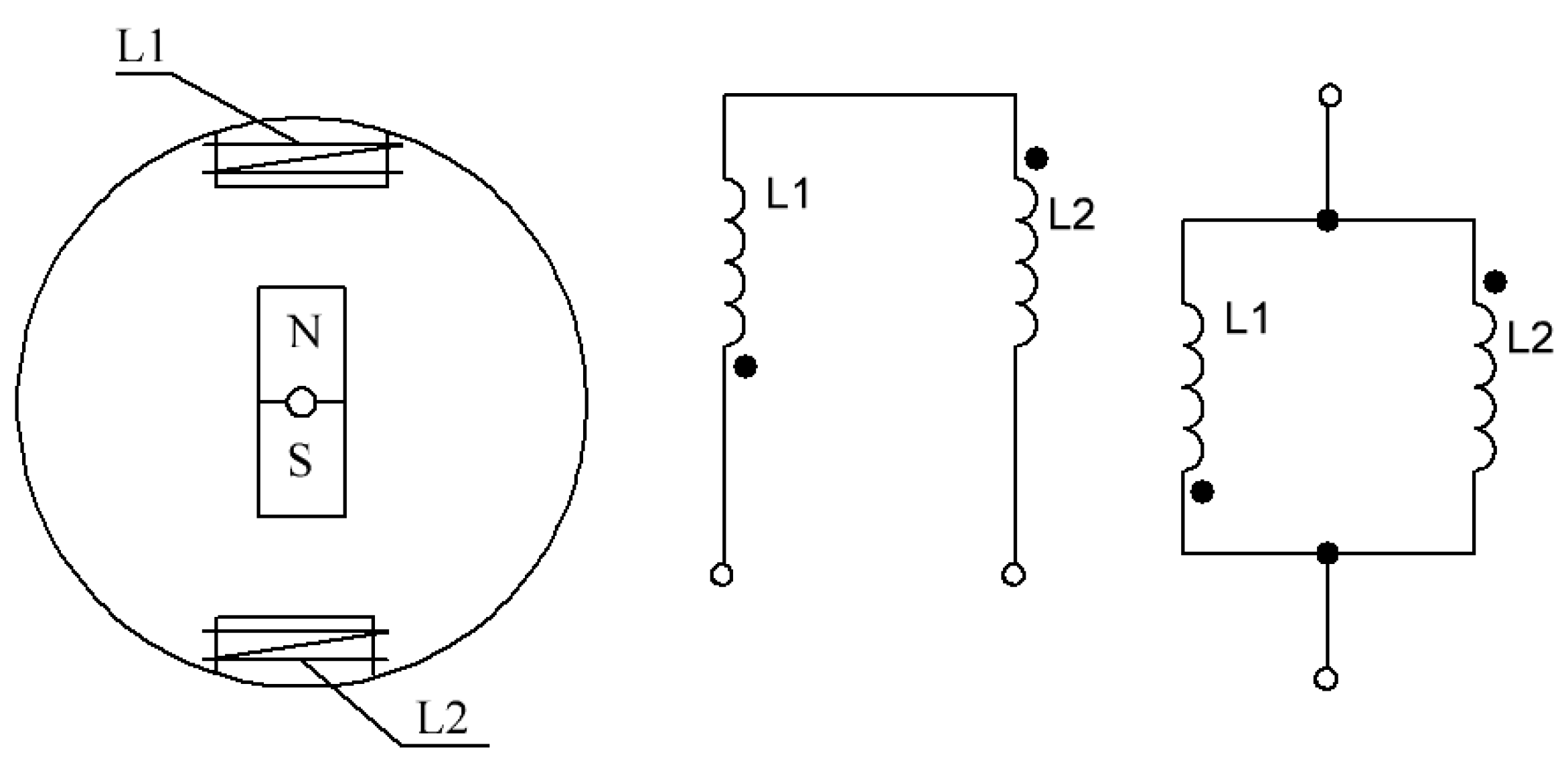
One of the simplest from the construction point of view is the generator with a compact design, shown in
Figure 1 [
19].
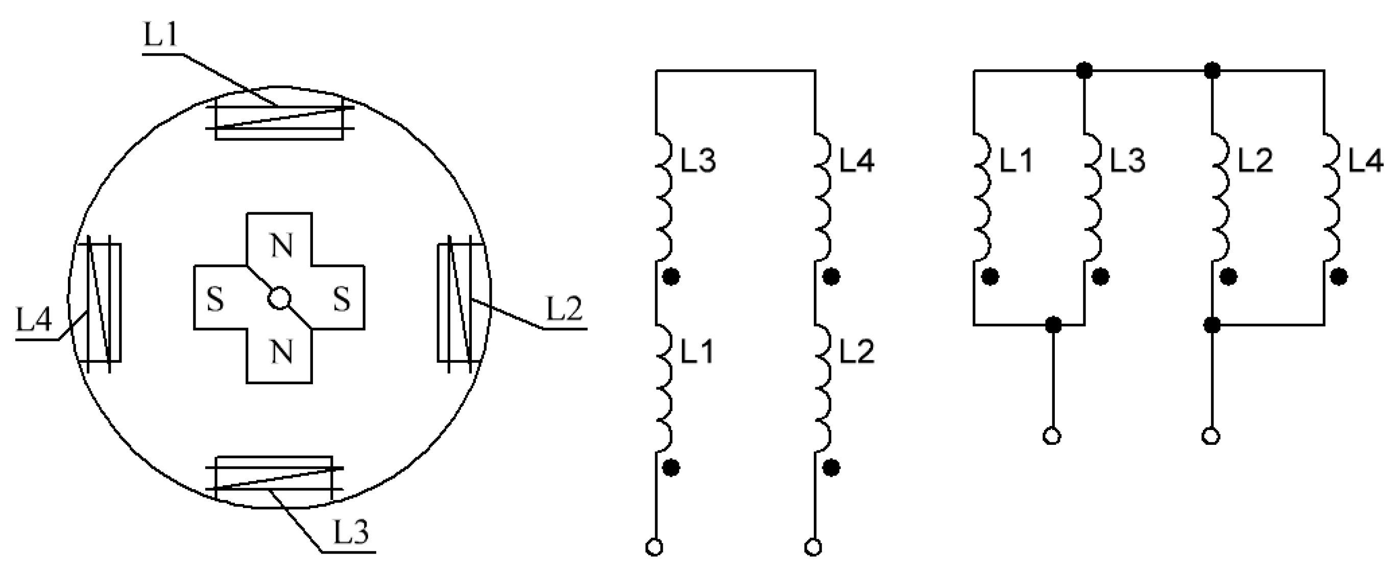
As it is shown in
Figure 1, the generator has one pair of poles on the rotor (2) in the form of permanent magnets and one pair of stator windings positioned diametrically opposite (1). These windings can be commutated in two different ways, which leads to an increase in the amount of generated power, as well as a change in one of the generated parameters—current or voltage. So, when the stator windings join up in series, the generated voltage increases twice, and when the stator windings are connected in parallel, the current flowing through the demand and generator increases twice.
Another version of the generator is a single-phase higher-capacity generator shown in
Figure 2 [
20,
21].
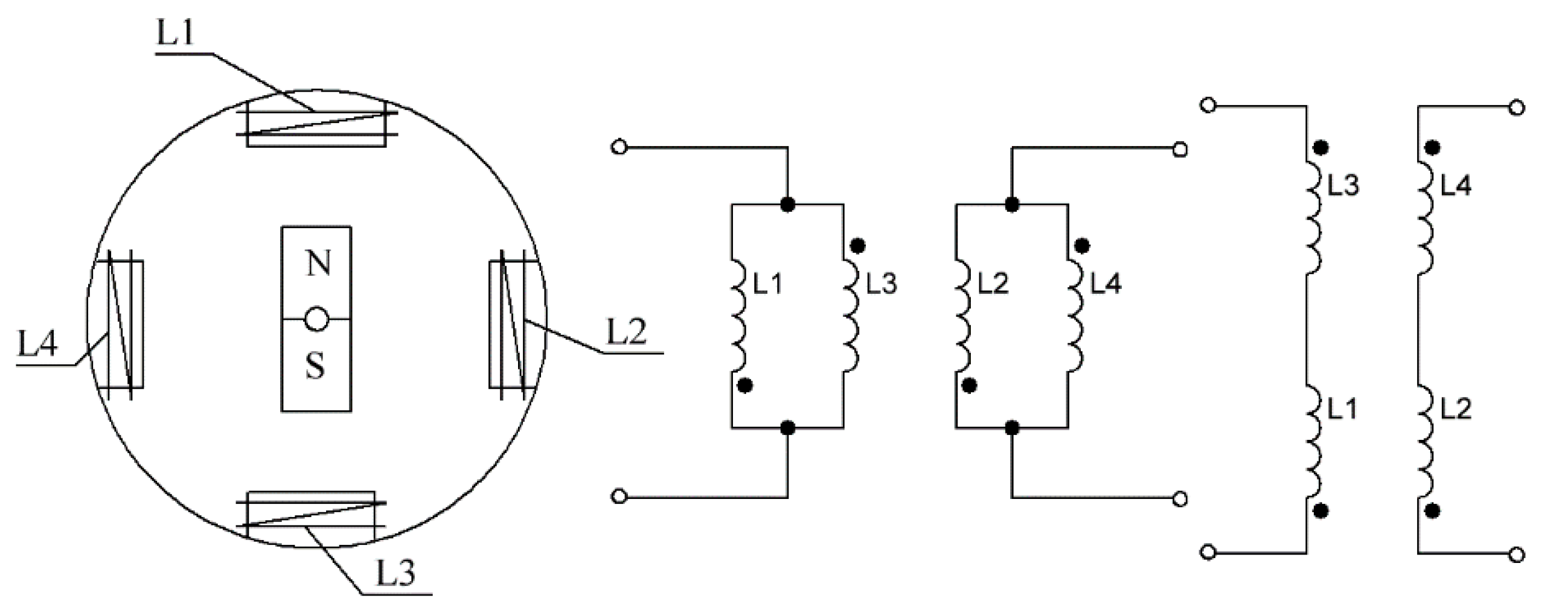
As it is shown in
Figure 2, the generator has two pairs of poles on the rotor in the form of permanent magnets, and two pairs of stator windings positioned diametrically opposite. This generator’s windings need to be switched in groups between each other into diametrically opposite windings, and these groups need to be switched among themselves to increase the generated power 4 times. When the stator windings and its groups are connected in series, it leads to an increase in the generated voltage by 4 times. When the stator windings are connected in parallel and the groups of these windings are connected in series, the generated current and voltage are doubled.
It is also possible to generate a two-phase voltage when using a two-phase generator [
22,
23].
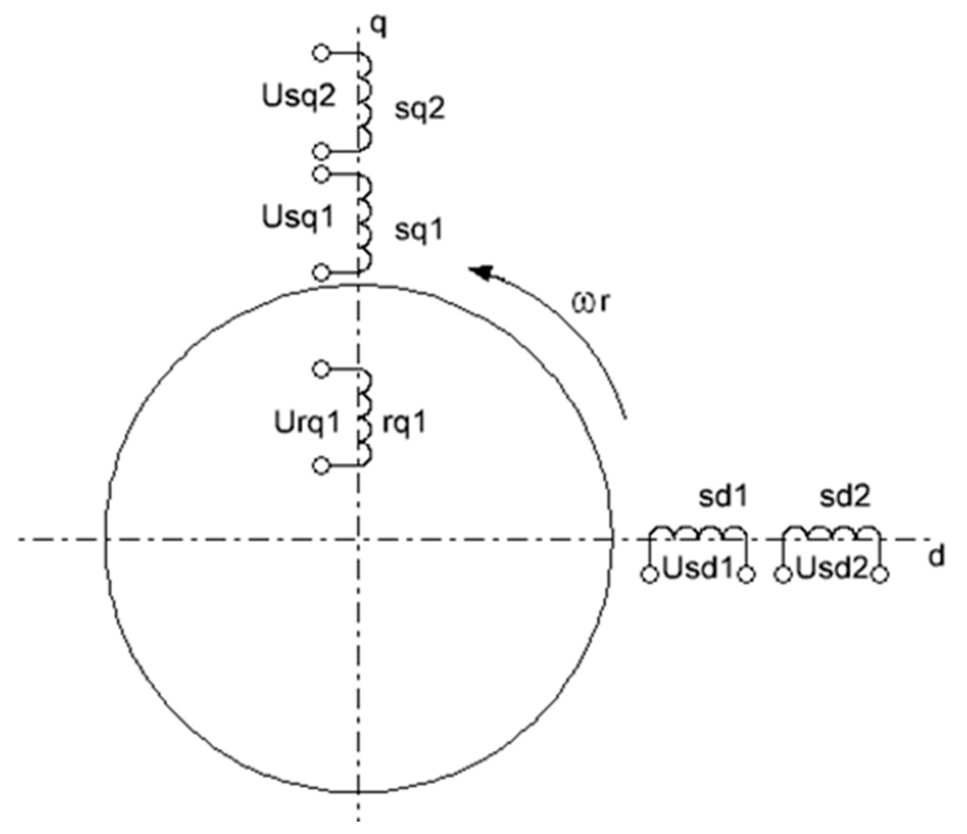
As it is shown in
Figure 3, the generator has a single pair of poles on the rotor in the form of a permanent magnet, and two pairs of stator windings positioned diametrically opposite. The windings of this generator need to be commutated in groups between each other into diametrically opposite windings to increase the generated phase by 2 times and to increase the generator capacity as a whole by 4 times. When in groups where the stator windings are connected in series, the generated voltage is entrained by 2 times in each phase. When in groups where the stator windings are connected in parallel, the generated current is doubled.
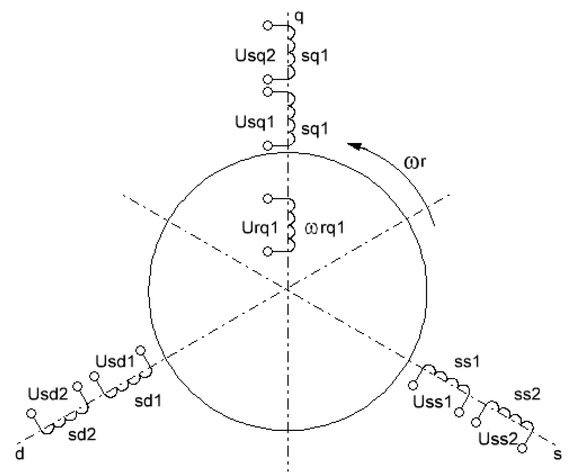
As it is shown in
Figure 4, the generator has single pair of poles on the rotor in the form of a permanent magnet, and three pairs of stator windings positioned diametrically opposite. These windings can be commutated in two different ways, which leads to an increase in the amount of generated power, as well as a change in one of the generated parameters—current or voltage. Thus, when the diametrically opposite stator windings are connected in series, and three groups of them have a wye-connection, the generated voltage increases twice in each phase. When the groups of stator windings are connected in parallel and these groups have a wye-connection, the phase current is entrained twice. As a result, the total power of the generator increases by 6 times relating to one of the phases.
3. Results
3.1. Mathematical Description
To conduct a study of the proposed multi-winding generators, it is necessary to develop a mathematical description. Drawing on the general provisions of EMF modeling, it is necessary to obtain the relationship between the voltage across the stator windings, flux linkage, and torque. Since the use of multi-winding generators is proposed, it is desirable to develop a body of mathematics that would become representative for these types of generators [
4,
20,
22,
24,
27,
28].
Hence, it is necessary to develop the description of the generator, that operates into an isolated load, represented as a take-off load, taking into account the fact that it is a new type of generator [
27,
28,
29,
30,
31,
32,
33,
34,
35].
According to the task of developing a mathematical description of modified PMSM, we develop a methodology for obtaining all four types of the above-stated generators from a unified description. To do this, we will use the standard means of describing the stator windings of an electric machine by Kirchhoff’s voltage law (1) to describe the complete voltage circuit of the stator winding, applied to the load, and the equation describing the complete flux linkage of the winding (2).
For this purpose, we develop a description for the single winding that could be duplicated further. So, in its equation, the voltage is replaced by complex load resistance (Zn) and is as follows:
where Ψ
wi—is a flux linkage of the stator winding,
iwi—are the stator winding currents,
Rw—is a coil resistance of the stator windings,
Zl—is the resistance of the autonomous load,
kn—is the number of windings connected on the same axis.
The definition of the flux linkage for the stator winding with the use of permanent magnets (Ψ
r) on the rotor is as follows:
where
aw is the coefficient of the geometric arrangement of stator windings,
Lw—is the stator windings inductance,
Ψ
r—is the rotor winding flux linkage, which is calculated for each winding as follows:
where
i is the consecutive number of stator winding,
k—the number of phases in which the stator windings are grouped,
ωf—is the rate speed of the rotor magnet field.
Let us solve the voltage (1) and flux linkage (2) equation system for Ψ
w1, so using the operational format, we obtain the following:
Since the generator is a current power supply, let us express the winding current as follows:
Let us introduce a new variable (ΔΨ
w), which will represent the flux linkage creating an EMF on this winding equal to the following:
To simplify the description of the winding load, a back coupling is formed:
Returning to the differential form, we obtain the following:
Taking into account the fact that ΔΨ is a subtraction of the magnetic induction vectors of all other coaxial and non-coaxial windings, and is not a flux self-linkage, rotating at a speed of ω, the derivative (differential) can be represented as an intersection of this vector and its speed, so the Equation (8) will take the following form:
The equation of motion has a classic form, but the equation that determines the torque changes, because it is determined through the active power developed by the machine, taking into account the new type of the developed generator. The equation has the following form:
where
Ew—is the EMF on the stator winding,
Pe—is an active power,
ωmech—is the generator shaft speed,
kM—is the number of rotor pairs of poles.
Using the presented mathematical methods (1)–(10), it is possible to describe each winding and obtain a mathematical model of the proposed modified multi-winding generators.
3.2. Mathematical Models
Drawing on the mathematical description (1)–(10) provided above, let us develop mathematical models based on the electric circuits of the generators.
The first case is a single-phase generator with a simplified construction. It is the simplest one in terms of mathematical description. So, according to the algorithm developed during the designing of its mathematical model, all the following models of the proposed multi-winding synchronous generators are developed.
So, the mathematical description of a single-phase generator (
Figure 5) with a compact construction, based on a synchronous generator with permanent magnets, is made according to the electrical model presented below [
19].
According to the general description of the generator presented in the previous chapter, let us assign the following coefficient value:
According to these coefficients, we compose the equations of voltages and flux linkages as follows:
The mechanical part of the generator is described as follows:
According to the obtained mathematical description of a single-phase generator with a simplified design, its mathematical model in “SimInTech” is created [
36].
Let us make a summary table with the coefficients for creating mathematical models of the proposed generators.
According to
Table 1 and the algorithm of the mathematical model (11)–(19) compiling obtained when compiling the mathematical model of a single-phase generator with a simplified construction, we make up the three mathematical models.
Using the electric circuit of the single-phase generator’s stator of increased power, shown in
Figure 6, we make a mathematical description (20)–(33) of the generator [
20,
21].
Using the electric circuit of the double-phase generator’s stator, shown in
Figure 7, we make a mathematical description (34)–(47) of the generator [
22,
23].
Using the electric circuit of the three-phase generator’s stator, shown in
Figure 8, we make a mathematical description of the generator.
Using the electric circuit of the three-phase generator’s stator, shown in
Figure 8, we make a mathematical description (48)–(67) of the generator [
24,
25,
26].
According to obtained mathematical description, it is possible to obtain the mathematical model in the program “SimInTech” [
36].
3.3. Mathematical Simulation
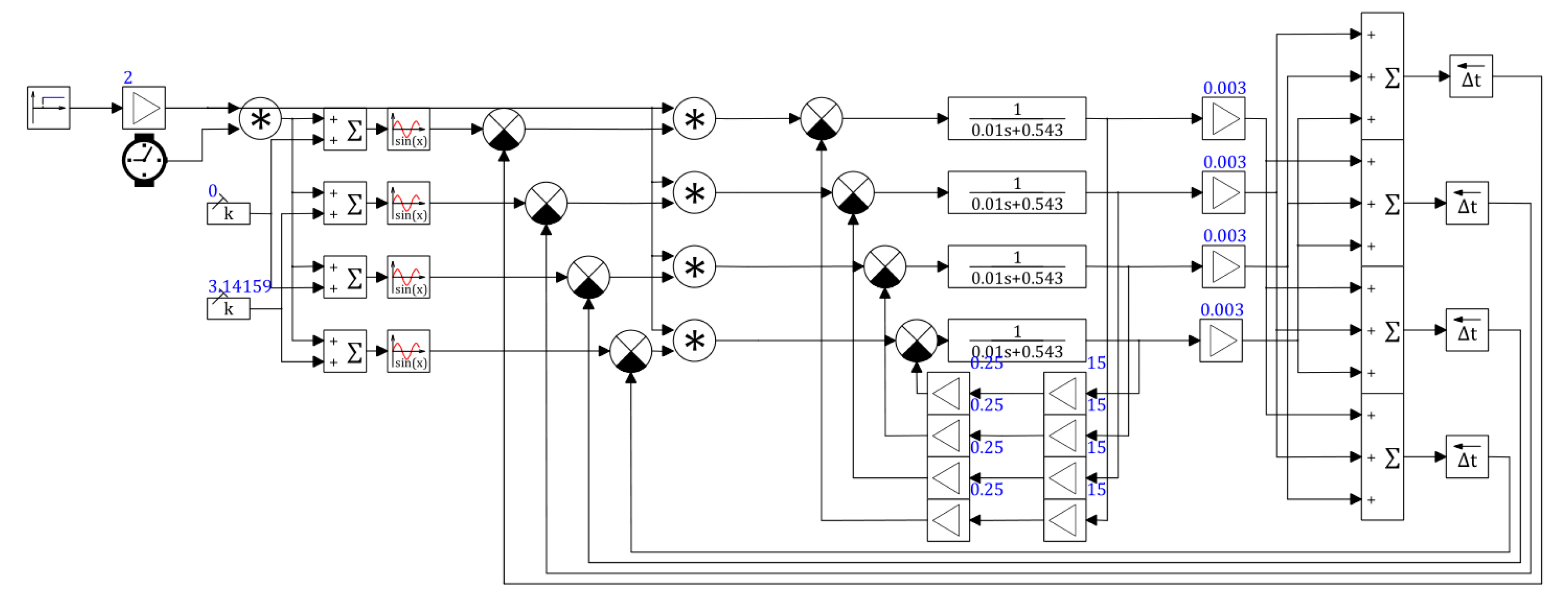
According to what is mentioned above, let us create the mathematical model in a “SimlnTech” simulation environment.
The simulation environment of “SimInTech” (Simulation In Technic) is an environment for the development of mathematical models, control algorithms, control interfaces, and automatic code generation for control controllers and graphic displays [
37,
38,
39]. SimInTech is designed for detailed research and analysis of non-stationary processes in various control objects. The development of mathematical models and control algorithms in SimInTech takes place in the form of the structural design of logical–dynamic systems described in input–output relations in the form of systems of differential equations and/or differential–algebraic equations [
37,
38,
39].
Since the most common generator operating condition is a static mode, mathematical simulation with the resistant torque and the electromagnetic torque developed by the generator being equal is considered. To generalize and simplify the study, the authors propose to consider only the active type of load as the most common type of load when studying the operation of the autonomous mode of operation of both low-power consumers and medium- and high-power consumers. It should be mentioned, that with the increase in consumer power, the influence of the inductive component of the load increases, and in the presence of energy storage devices, the influence of the capacitive component of the load increases, depending on the operating mode. Therefore, to simplify the study of the functioning schemes of generators and to compile primary algorithms for operation and regulation of the generated parameters, it is most logical to study only the active component of the load.
Let us consider the mathematical model of a single-phase generator with a simplified construction, using the mathematical description presented above (12)–(19), shown in
Figure 9. The data given in
Table 2 [
40] are used as reference data for the modeling of this and all subsequent generator models.
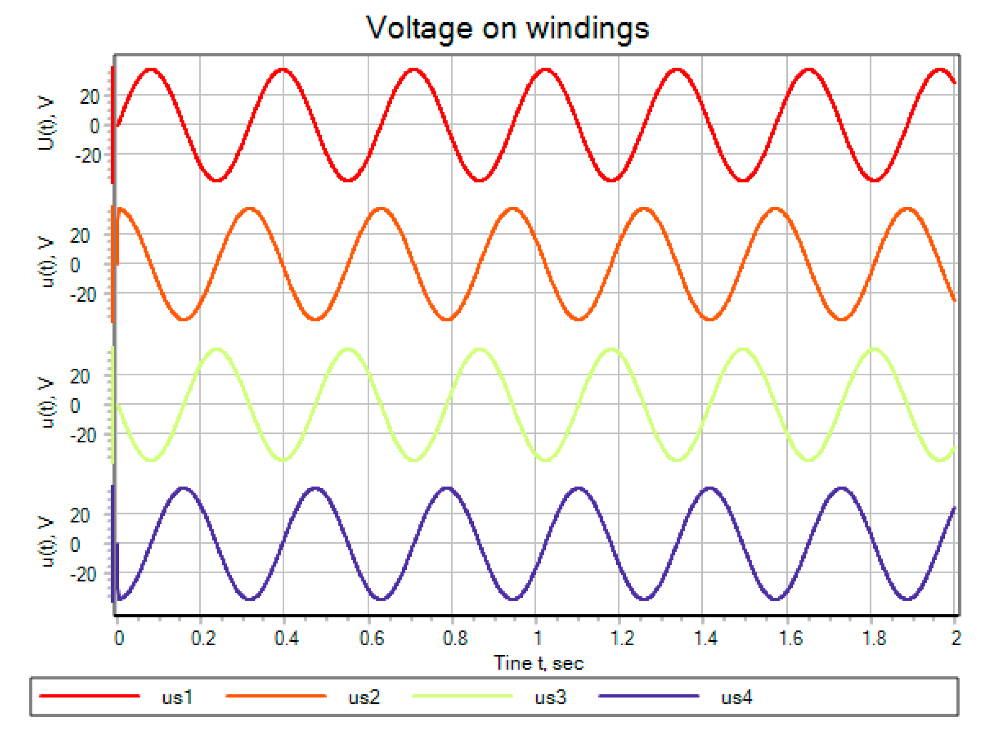
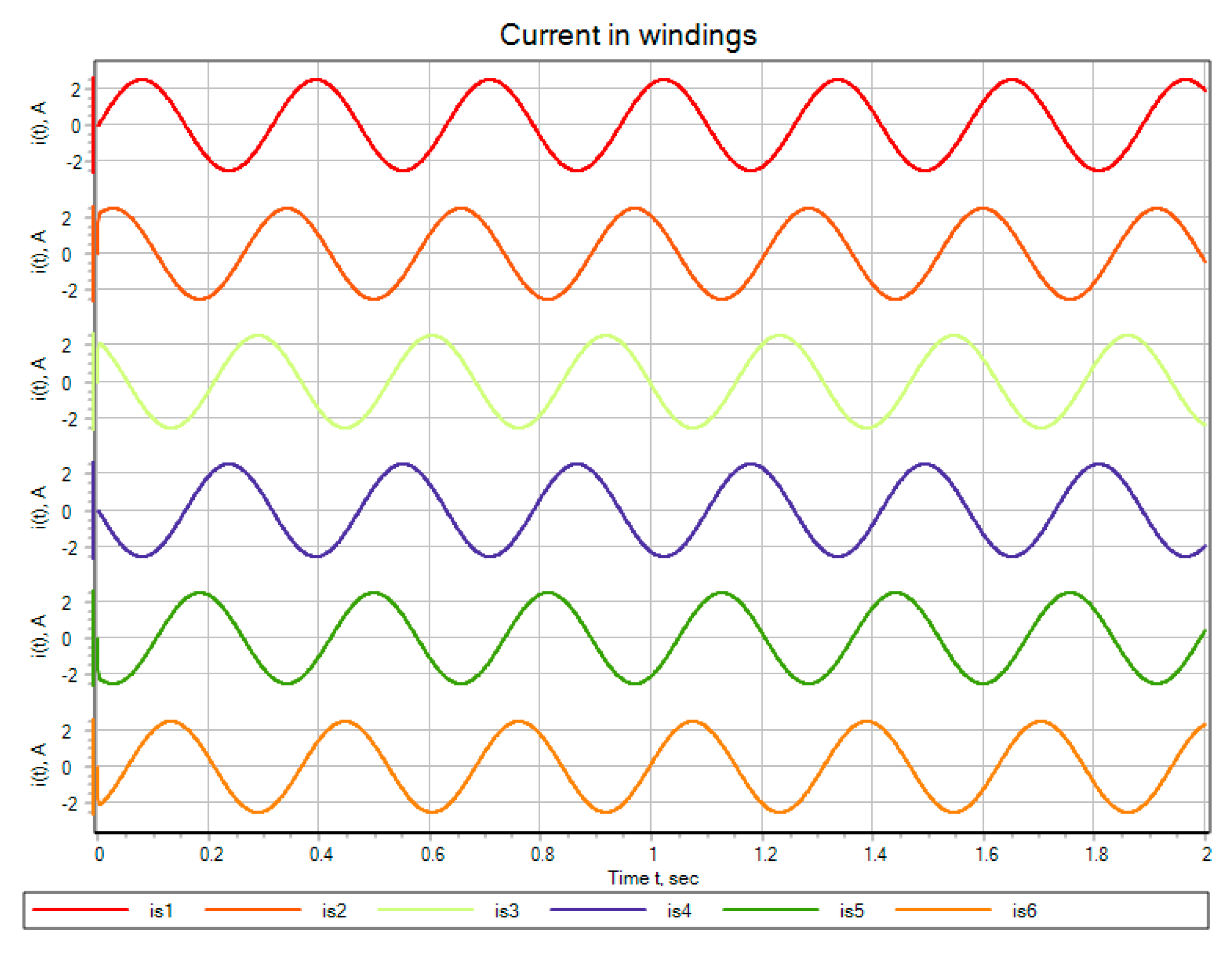
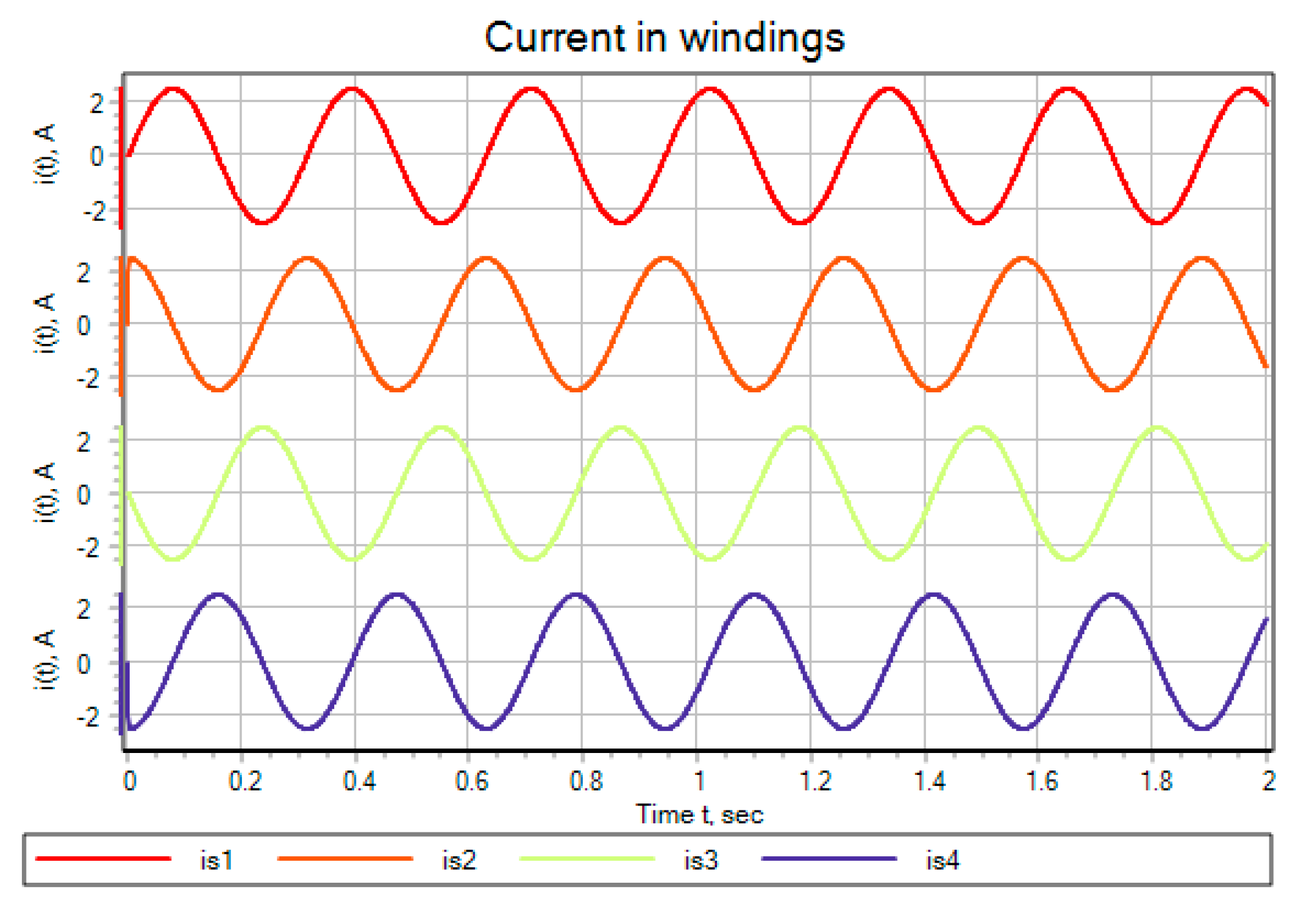
As a result of mathematical modeling, diagrams of the currents flowing through the stator windings, the load, and the voltage on each of the windings were obtained (
Figure 10). The diagrams, reflecting the values of voltage and current, generated using a special connection of the stator windings were obtained. The comparison between these values and the values, obtained from the generator windings, was made (
Figure 11 and
Figure 12).
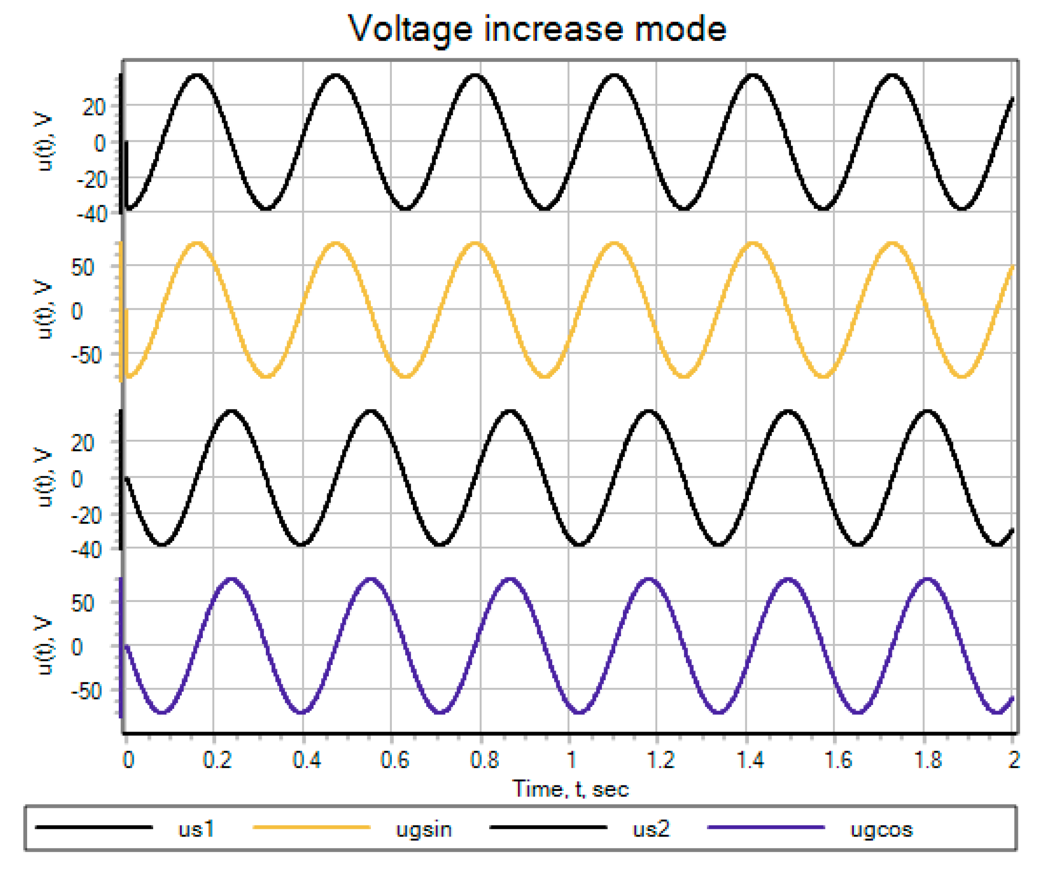
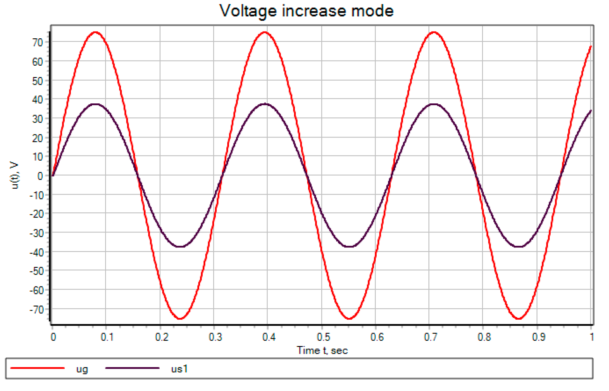
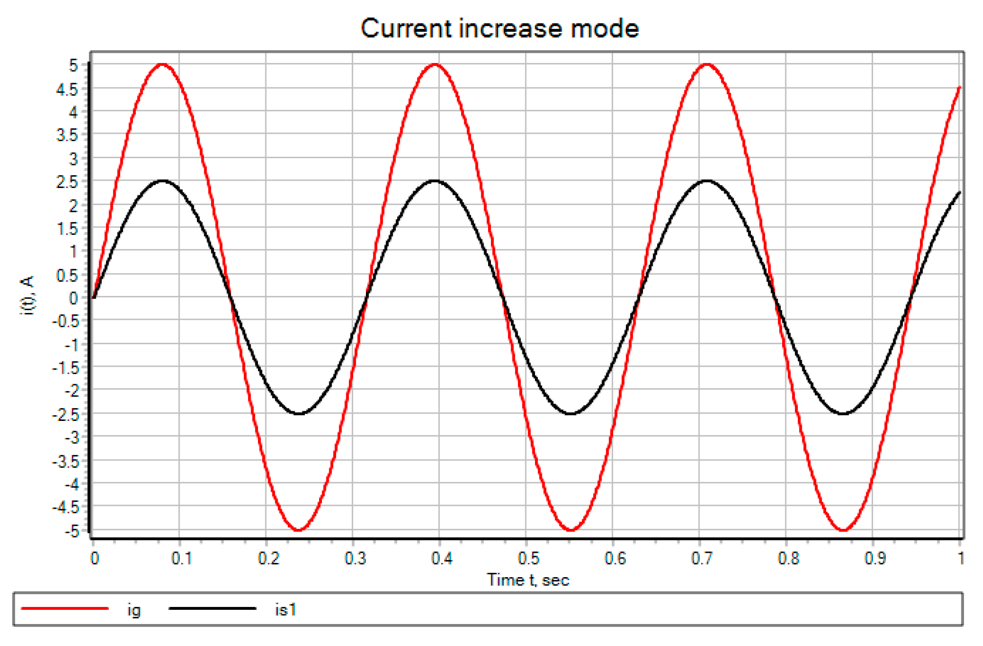
According to
Figure 11 and
Figure 12, the generated parameters, such as the generated voltages and currents are increased. So, according to
Figure 11, there is an increase in produced total voltage by 2 times relative to the value on a single stator winding. When considering
Figure 12, there is an increased generation of the current, flowing in the stator windings and through the load twice relative to the generated current of one winding.
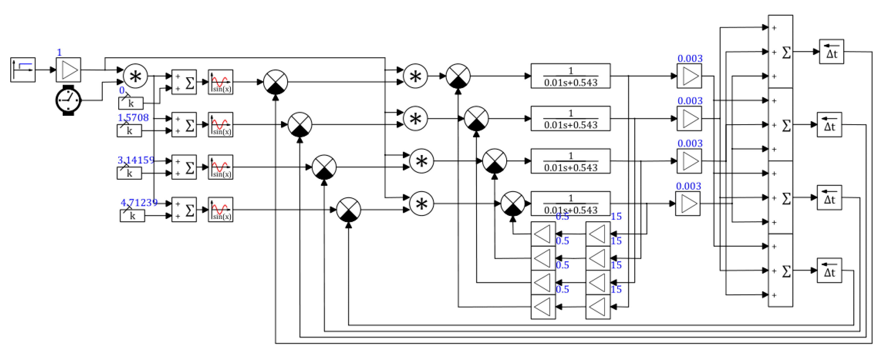
The mathematical model, designed using the above-mentioned mathematical description (20)–(33) of a single-phase higher-capacity generator is shown in
Figure 13 [
20].
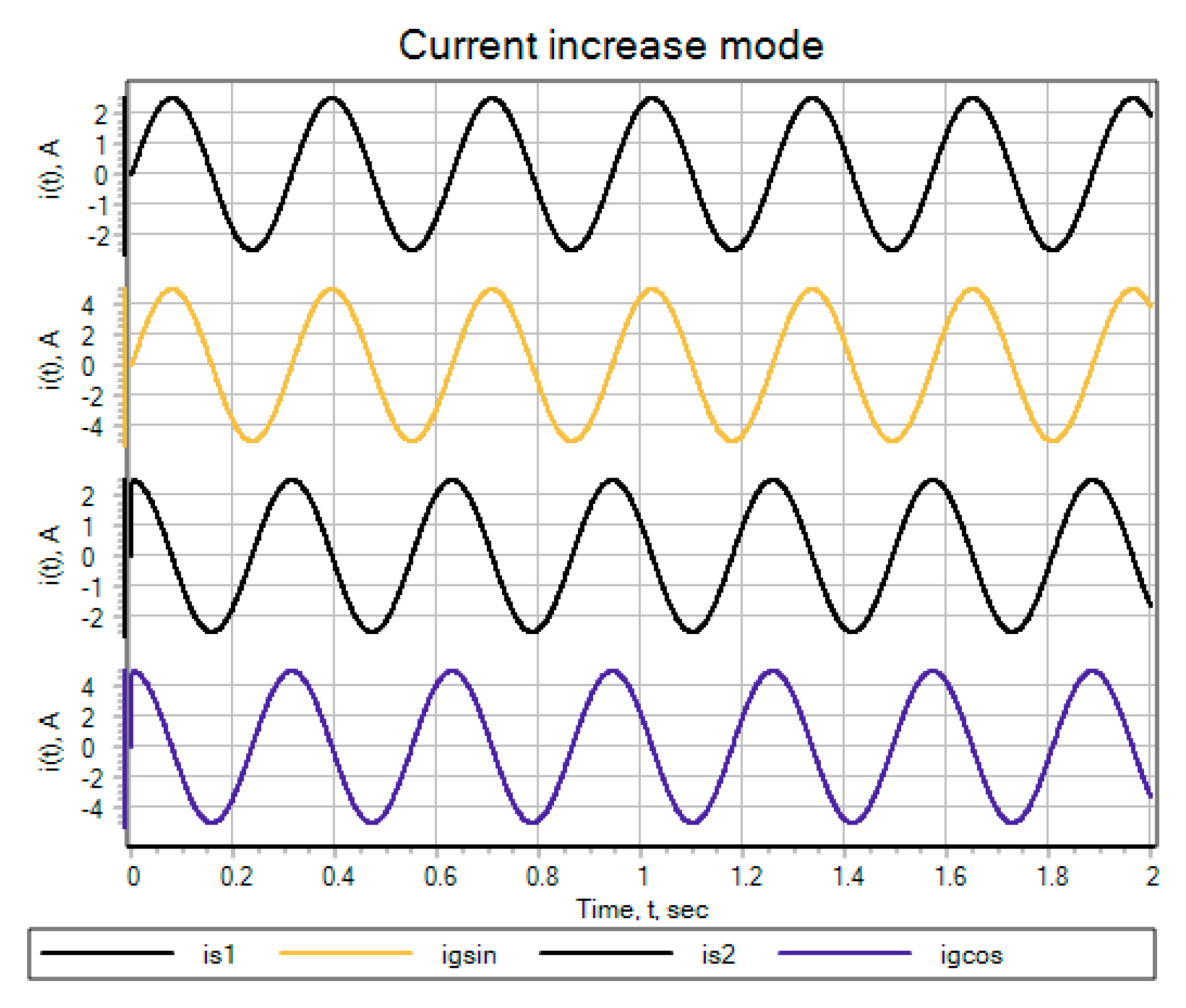
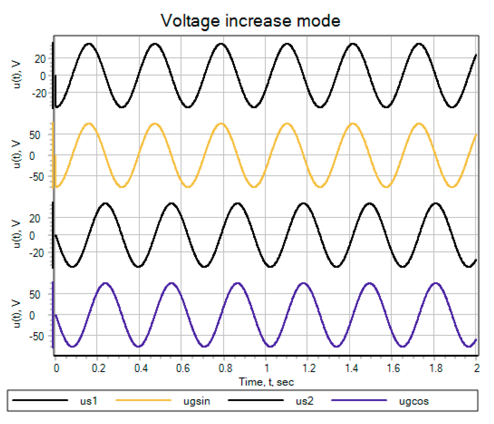
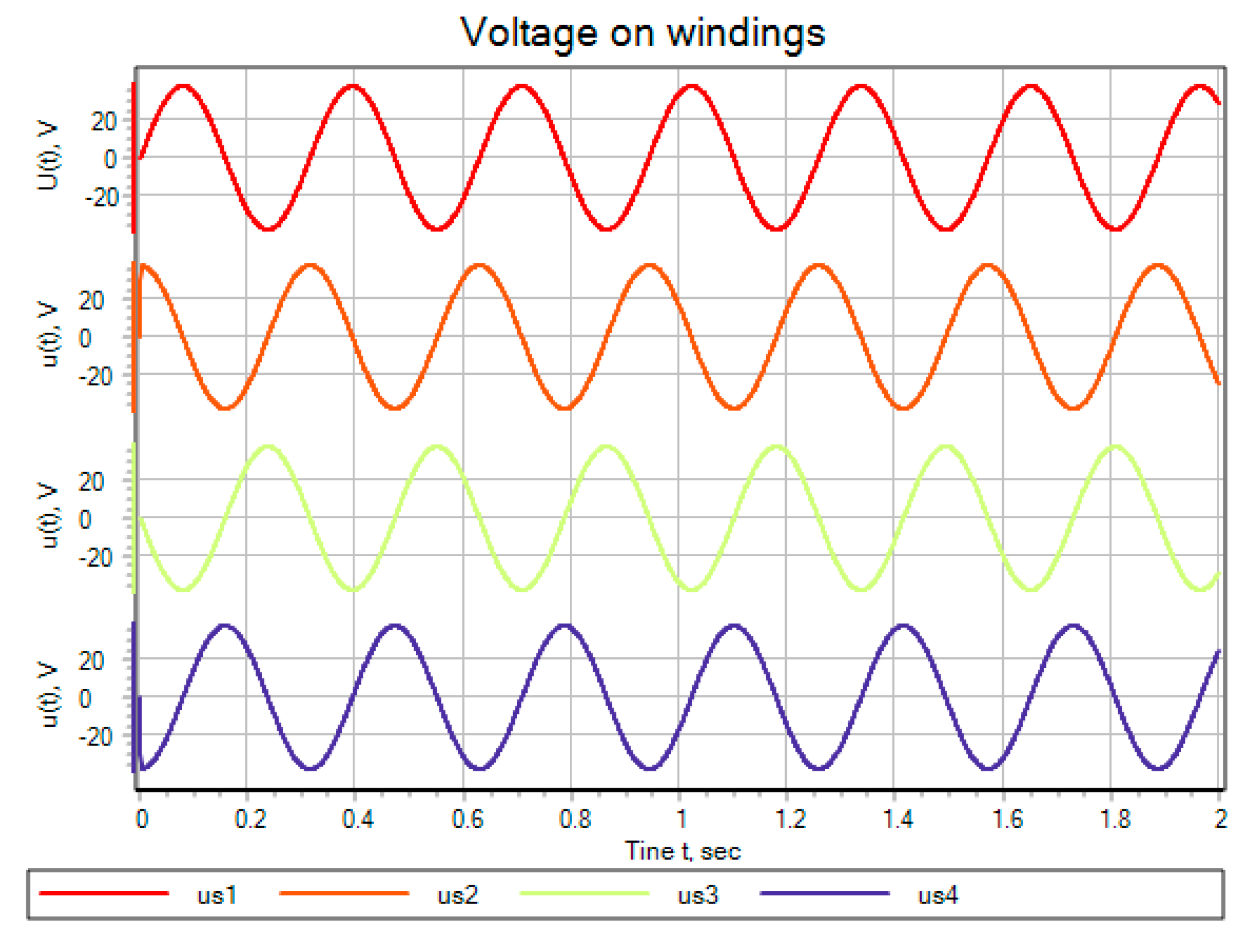
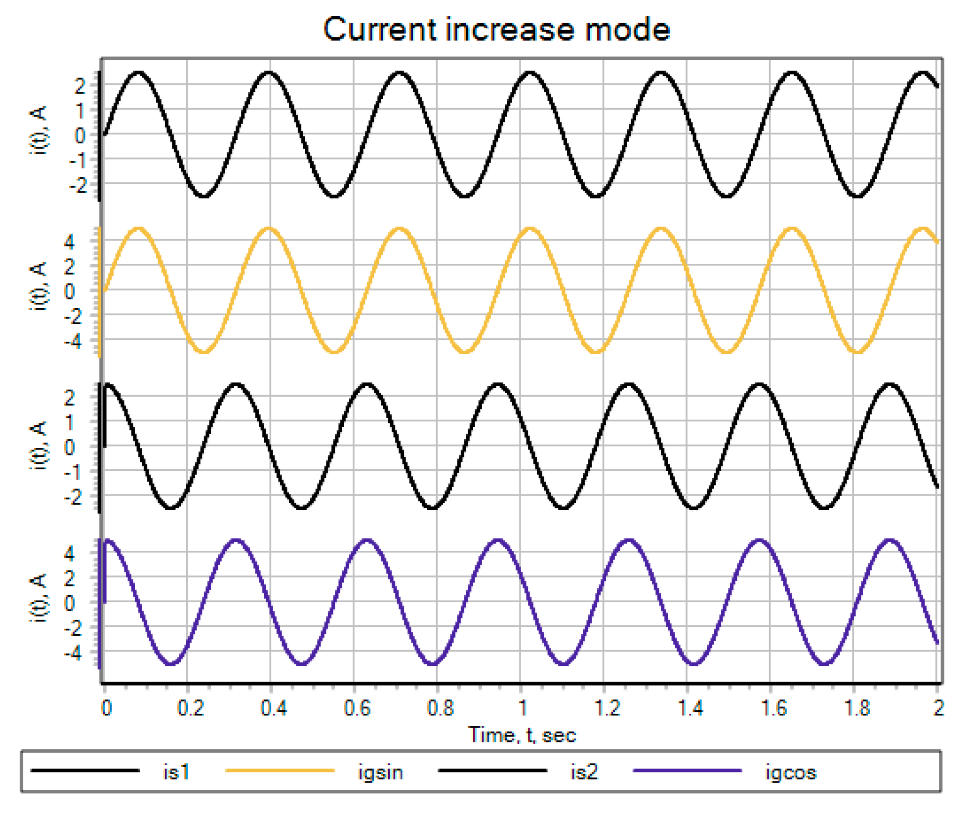
As a result of the simulation, the relationships between the currents, flowing in the stator windings (
Figure 14), the voltage on the stator windings (
Figure 15), the current in the generator load, the voltage at the series-parallel connection of the stator windings and the voltage on the generator load at the series connection of the stator windings (
Figure 16 and
Figure 17) were obtained.
Thus, according to
Figure 16, when using a series-parallel connection of the stator windings in static mode, both the generated current and generated voltage are doubled. When all the windings are connected in series, according to
Figure 17, the generated voltage is quadrupled.
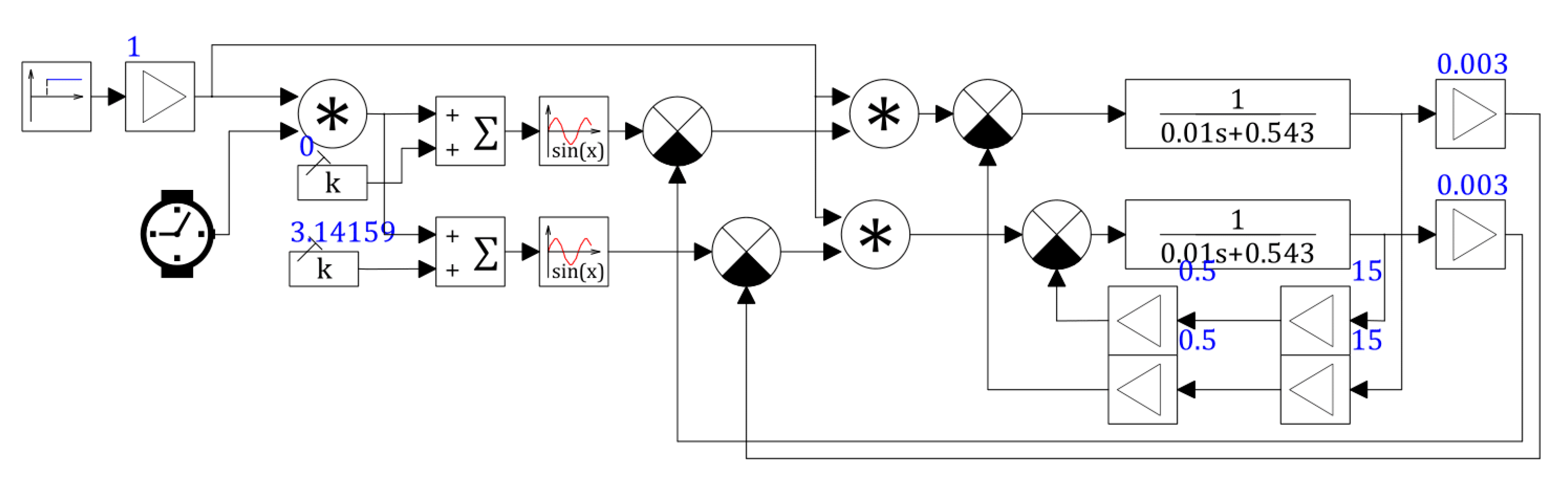
Using the mathematical description presented above, we have to create a two-phase generator’s mathematical model (34)–(47), shown in
Figure 18 [
22].
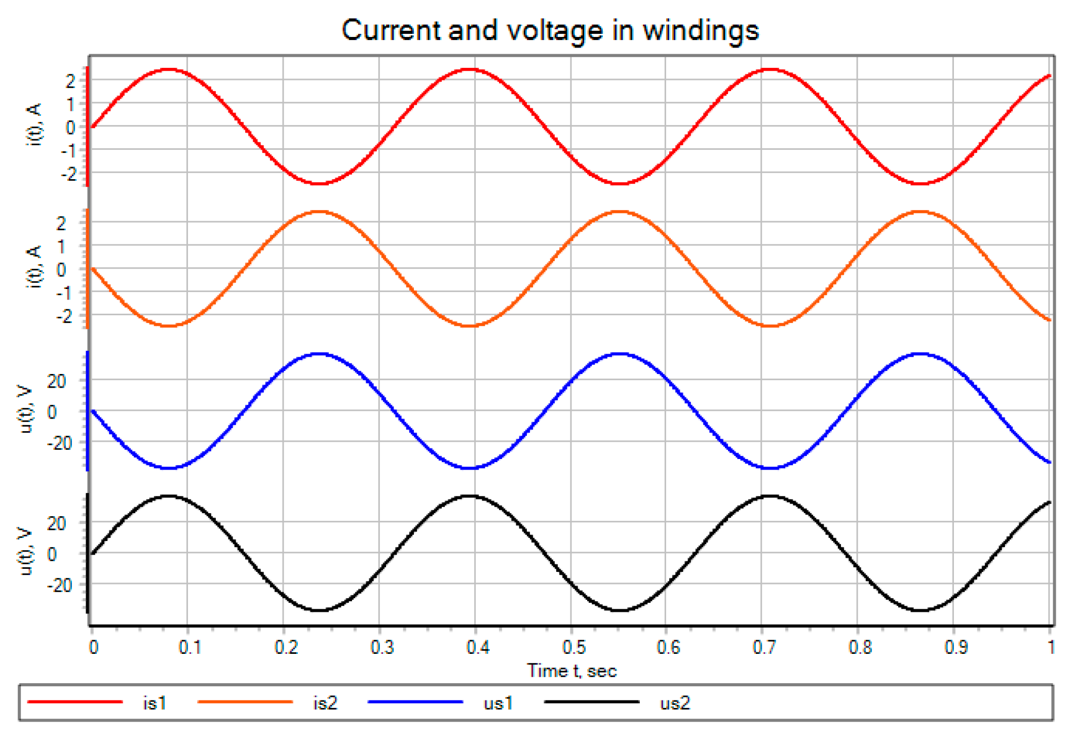
As with all mentioned mathematical models, the diagrams for the parameters of the generator windings, such as current (
Figure 19) and voltage (
Figure 20), and the current and voltage parameters for parallel (
Figure 21) and series (
Figure 22) connections of the stator windings, were obtained.
According to the figures, it is obvious that when using a parallel phase-by-phase connection of the stator windings, the current flowing through the load is carried away twice (
Figure 21), and when the stator windings are connected in series (
Figure 22), the generated voltage is doubled.
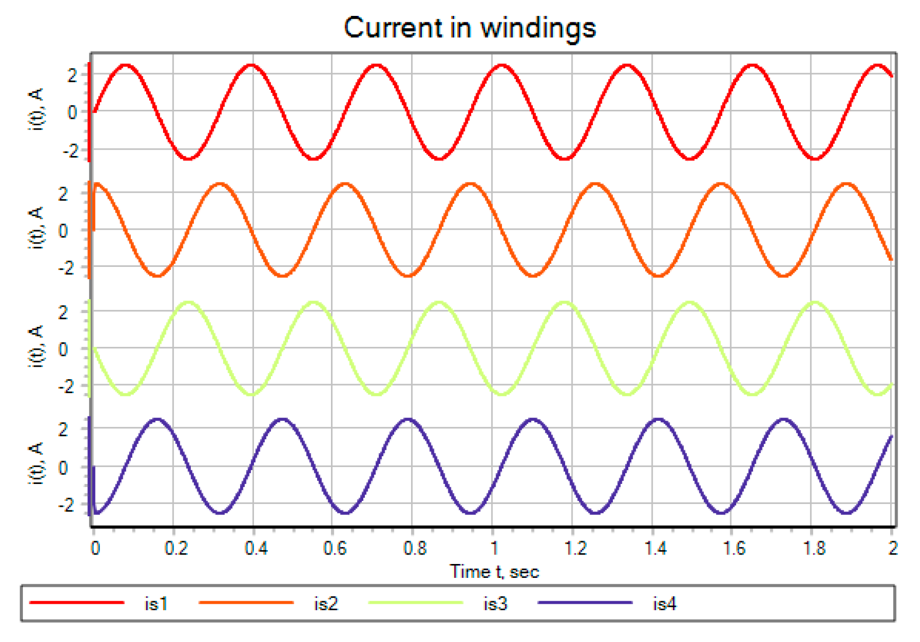
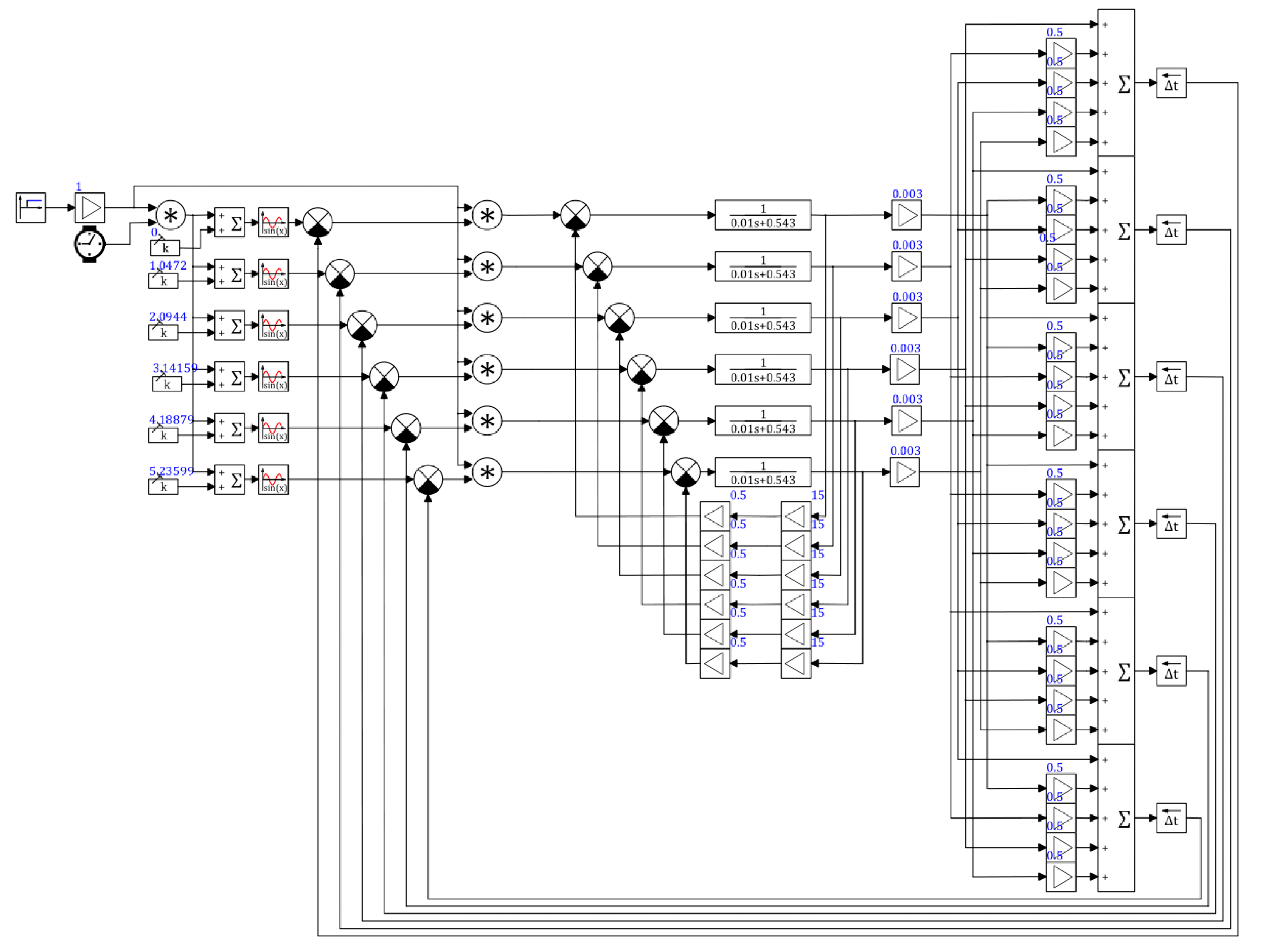
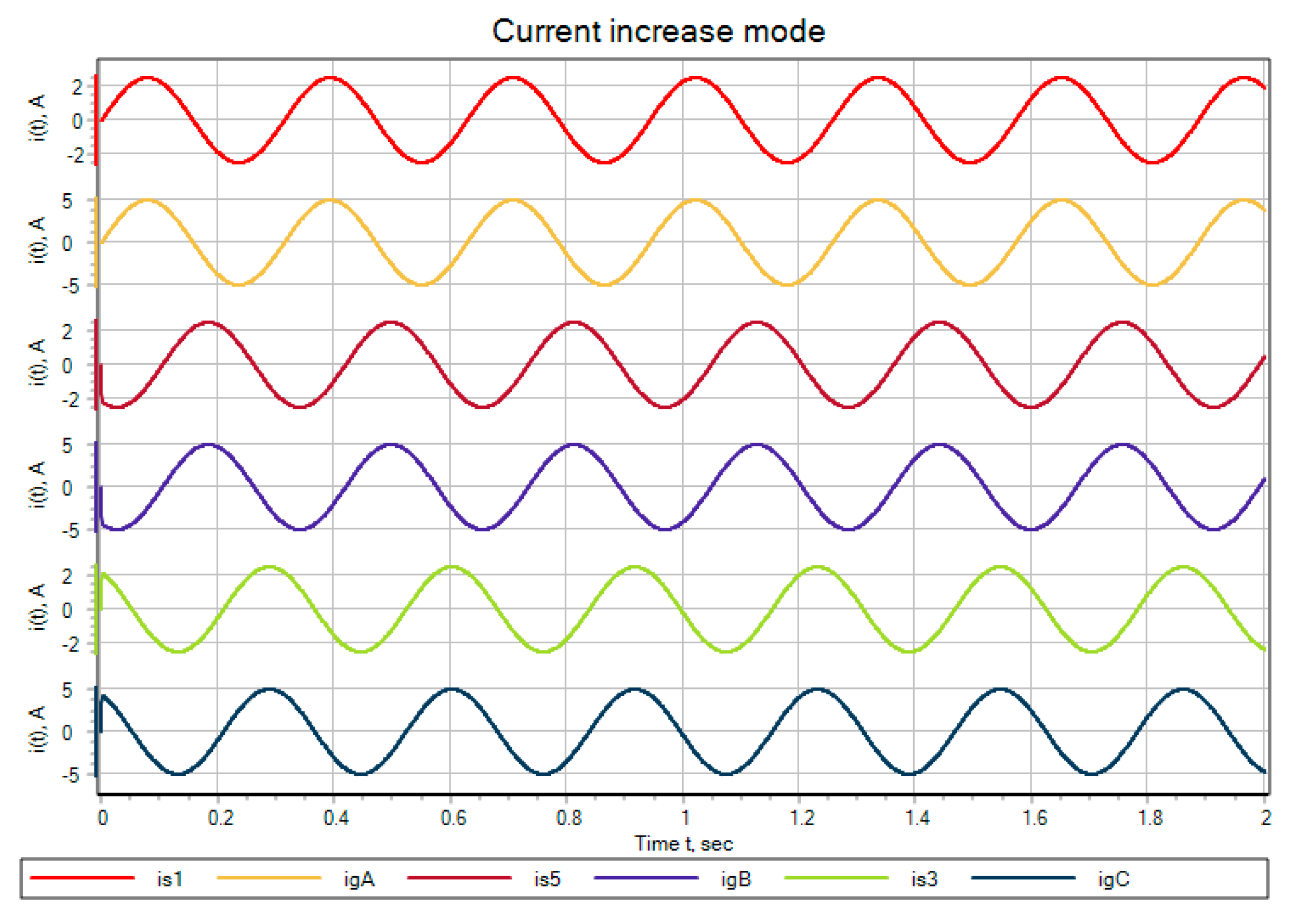
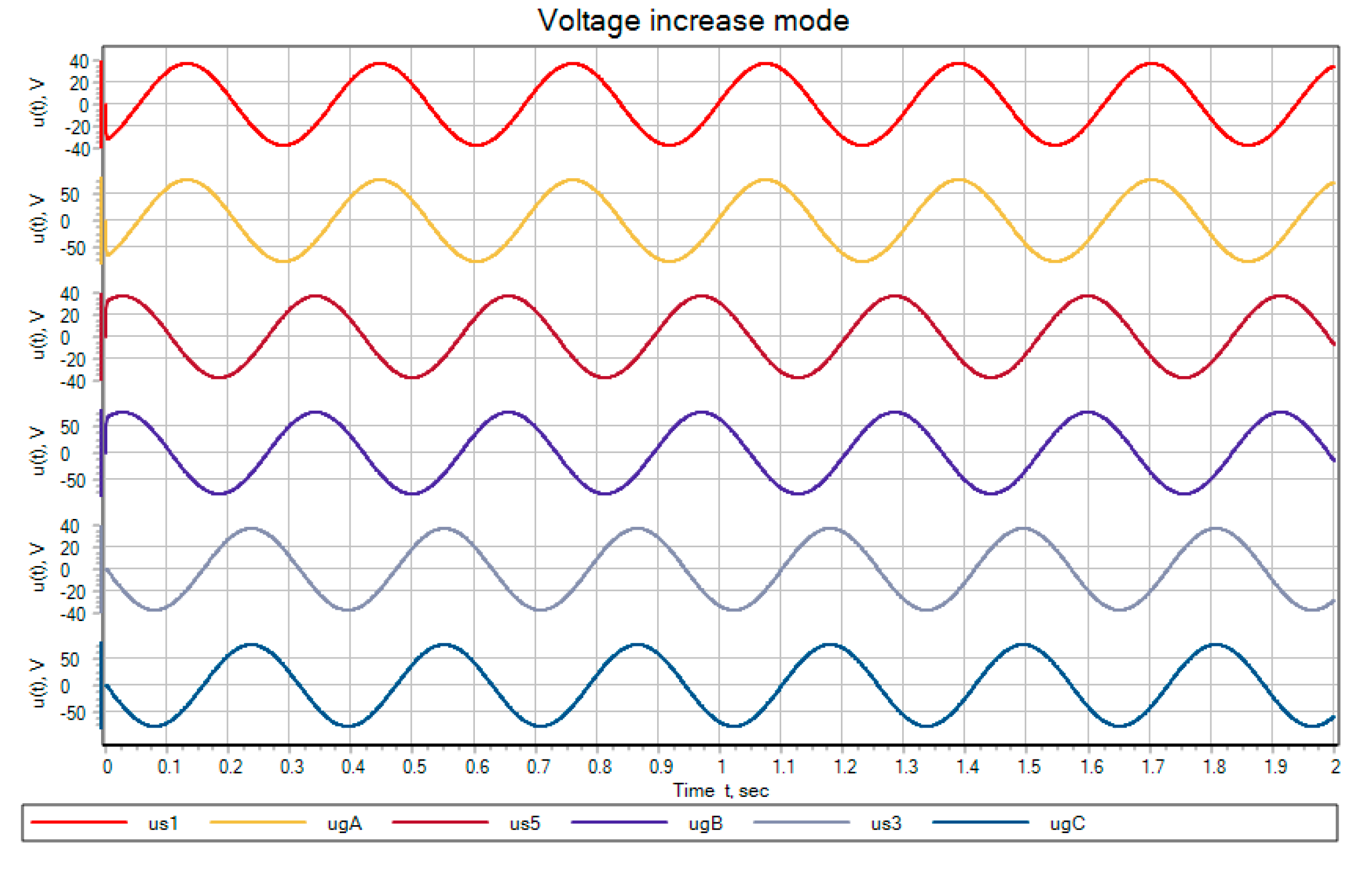
According to the proposed mathematical description (48)–(67), we obtain a mathematical model of a three-phase generator (
Figure 23) [
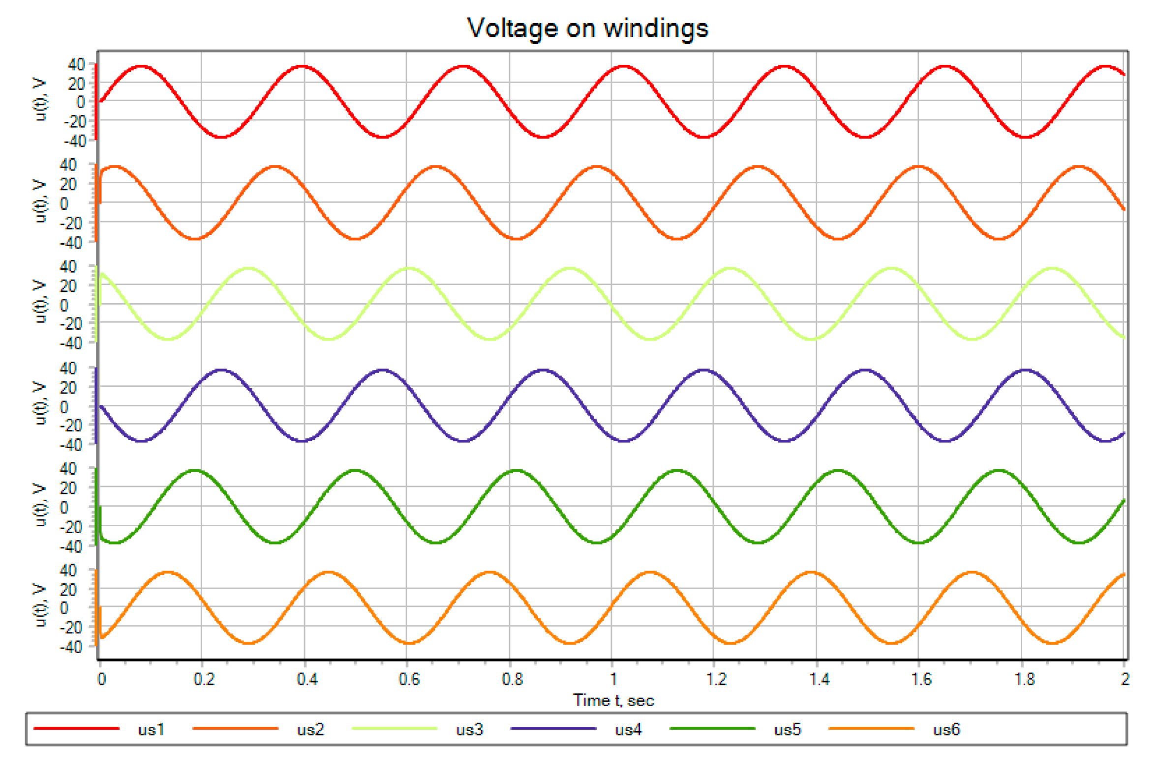
24] and its parameters: the current flowing in the stator windings (
Figure 24); the voltage on the stator windings (
Figure 25); the current when the stator windings are connected in parallel (
Figure 26); and the voltage when the stator windings are connected in series (
Figure 27).
According to
Figure 26 and
Figure 27, the generated parameters, such as generated voltages and current, are increased. So, according to
Figure 26, there is an increase in produced total voltage by two times relative to the value on a single stator winding. When considering
Figure 27, there is an increased generation of the current flowing in the stator windings and through the load twice relative to the generated current of one winding.
4. Discussion
According to the carried out mathematical modeling, it can be said that the proposed generators allow increasing the controllability of the energy complex that generates electricity for an autonomous consumer of different architecture of electrical system building (single-phase, two-phase and three-phase classic). It also allows increasing the boundary conditions of operation of several sources, using electromechanical converters. Examples of such energy sources are wind turbines, mini- and micro-hydroelectric power plants, biogas plants, etc. Improving the controllability and expanding the boundaries of working conditions is provided by the possibility of regulating the ratios of generated currents and voltages, allowing them to reduce the volume of its flow with an excess of generated power, reducing the amount of current and increasing the voltage, which can be additionally regulated by the buck-converter, or with a lack of energy to reduce the amount of generated voltage, increasing the volume of generated current by increasing the possibility of overloading the generator by current through transferring its volume among the windings connected in parallel. In addition, the generators expand the boundaries of the operation of a generating unit, for example, the operation of a wind generator, which is limited in wind speed to both the lower value of the speed and the maximum value of the wind speed. This is also possible thanks to changing the stator windings connection, which helps to double both the lower and upper limits of the operating speed of the wind generator.
To further study the modes of operation of generators in the power supply complex of an autonomous consumer, the authors suggest conducting additional research, namely, the architecture designing of the power supply network and power converter technology, which will depend on the power and type of consumer, and which will best and most fully satisfy the energy and quality indicators. However, based on the results of mathematical modeling and systematic study of existing similar types of generators, generating systems, and complexes, we can draw a conclusion on the influence of the proposed types of generators on the development and modeling of both power converters and control systems. It can be argued that the power contour of the power supply system will operate in a quasi-steady-state mode, which will simplify the mathematical description of semiconductor converters and reduce it to transmission coefficients both in current and voltage.
Obtaining complex mathematical models of the developed types of generators will require additional research in the field of both types of energy sources and mechanical converters, which, analogous to the development of the power part of the power supply system, is associated with the capacity of a specific consumer. In addition, climatic factors of operation of the power supply system of an autonomous consumer have great influence, especially wide temperature ranges of the possible place of operation, particularly in the regions of Siberia.
The above-proposed solutions will allow for a more detailed and comprehensive analysis of the application of autonomous consumer power supply systems, using the proposed generators to analyze their possible potential.
5. Conclusions
In this article, the analysis of existing methods of autonomous consumers’ power supply was made, and the solution, connected with the use of synchronous magnetoelectric generators for autonomous consumers power supply, was proposed. To minimize the drawbacks of this type of generator, it was suggested to use multi-winding synchronous generators with excitation from permanent magnets. Several synchronous generators with different configurations were proposed. They are one -, two- and three-phase generators that not only have better properties of electricity generation—in particular, increased values of power, current, and the voltage produced by the generators—but they also have better regulatory properties: they can regulate the generated values of current and voltage without loss of power. Not only are the classical three-phase generator with permanent magnets with minor changes in the rotor design considered in detail, but also the single-phase and two-phase generators, which allows expanding the scope of the proposed mathematical models for studying not only the traditional three-phase consumer power supply network, but also other types of networks. For example, a two-phase network can be used in electrical complexes with a two-phase electric drive, which can be equipped with private seasonal production both in the field of agriculture and in the textile industry. A generator for a single-phase power supply system was also considered. It fits, for example, for a low-power consumer without the need to redistribute the load between phases to eliminate phase misalignment, as well as the exclusion of additional devices to eliminate emergencies arising from phase misalignment.
In addition, the obtained mathematical descriptions of generators were unified. This will help to obtain mathematical models of the proposed generators to study their use in generating complexes of the power supply system of an autonomous consumer, taking into account the phase of the generator and the method of connecting the stator windings. The proposed approach differs from the existing ones, which offer two basic principles. The first principle describes only one fixed, unchangeable configuration of the connection of the stator windings, aimed at creating a cleaner sinusoidal signal taken from the generator or, for the motor mode, providing a more uniform rotating magnetic field of the stator. The second principle describes the introduction of additional windings into the stator to obtain generators of a greater phase to redistribute power between the phases of the generator, or to reduce the cost of the DC voltage insertion design to exclude filtering devices. Both of the proposed standard methods do not describe the regulation of the generated parameters directly on the generator side with minimal use.
Mathematical descriptions for all the presented types of generators are proposed, as well as the mathematical modeling of the static mode of operation of the generators, using the SimInTech mathematical modeling software package, the results of which are presented in the work.
In the future, it is suggested to continue the study of the proposed generators as part of the agent of the generating complex, with a more detailed analysis of the mechanical part of the drive, taking into account climatic factors. In addition, it is suggested to develop the power part of the circuit, which will allow obtaining a complete model of the agent of the generating complex of the power supply system of an autonomous consumer.


