Abstract
The influences of superellipse shapes on natural convection in a horizontally subdivided non-Darcy porous cavity populated by Cu-water nanofluid are inspected in this paper. The impacts of the inner geometries Rayleigh number , Darcy number , porosity , and solid volume fraction on nanofluid heat transport and streamlines were examined. The hot superellipse shapes were placed in the cavity’s bottom and top, while the adiabatic boundaries on the flat walls of the cavity were considered. The governing equations were numerically solved using the finite volume method (FVM). It was found that the movement of the nanofluid upsurged as Ra boosted. The temperature distributions in the cavity’s core had an inverse relationship with increasing Rayleigh number. An extra porous resistance at lower Darcy numbers limited the nanofluid’s movement within the porous layers. The mean Nusselt number decreased as the porous resistance increased . The flow and temperature were strongly affected as the shape of the inner superellipse grew larger.
1. Introduction
A wide range of applications, including geothermal systems, high-performance building insulation, the control of pollutant spread in groundwater, postaccident heat removal from nuclear reactor rubble beds, solar power collectors, and compact heat exchangers have made fluid flow and heat transfer in porous media a hot topic in recent decades [1,2,3,4]. Many different papers on numerical and experimental analysis of natural convection in porous cavities have been published. Natural convection in an inclined confined area filled with a fluid-saturated porous medium was numerically explored by Alloi et al. [5]. They discovered that the inclination angle of the porous layer and the shape of the drag parameter had a significant impact on the heat transfer strength in a closed area. Dixon and Kulacki [6] investigated flow and heat transfer in a liquid-layer saturated porous bed that was heated from the bottom. They developed general heat transfer laws for varied porous bed depths for use in process industries, environmental science, and materials processing.
Astania et al. [7] used the Brinkman-extended Darcy model for porous layers to numerically analyze natural convection combined with entropy generation of –water nanofluid within an open trapezoidal cavity filled with a porous layer and a ferrofluid layer under the influence of a uniform inclined magnetic field. The finite difference approach was used to perform numerical analysis. It has been observed that the inclination angle depicts heat and fluid flow behavior that is unstable. Heat and fluid flow have an unstable characteristic.
Research on fluid flow in cavities of various geometric shapes has expanded rapidly due to its importance in heat transfer improvements. Cho et al. [8] examined natural convection augmentation of an -water nanofluid surrounded by a U-shaped cavity. Numerical attempts at determining convection flow within a T-shaped cavity were made by Esfe et al. [9]. Bohowmick et al. [10] examined natural convection in a valley-shaped cavity occupied by stratified water. Teixeira et al. [11] investigated the temperature field behavior of a square plate with T-/H-shaped cavities. Mikhail et al. [12] performed a numerical analysis of the natural convection of an -water nanofluid in a differentially heated square cavity partially filled with a heat-generating porous medium. The Darcy-extended Brinkman model was used, and they found that the heat transfer coefficient at the fluid/solid matrix interface was an effective control parameter for convective flow and heat transfer intensity. Using a magnetic field and thermal radiation, Sreedevi and Sudarsana [13] examined the natural convection of TiO2-EG nanofluid in a square cavity with adiabatic walls. Further studies include [14,15,16,17,18,19].
Due to the Boussinesq approximation’s rapid convergence and ease of implementation, it is used in most natural convection research. Benchmark results for flow in a cavity were introduced by De Vahl Davis [20]. Szewc et al. [21] compared Boussinesq and non-Boussinesq approximations. The nonlinear Boussinesq approximation of a micropolar non-Newtonian fluid was inspected by Srinivasacharya et al. [22]. Sameh et al. [23] employed the nonlinear Boussinesq approximation for a sinusoidally heated porous enclosure loaded with a nanofluid.
Various numerical studies [24,25,26,27] have been carried out to describe the convective heat transmission of coupled nanofluids with porous media. Jami et al. [28] used a square cavity in conjunction with partially heated vertical sides to study several types of nanoparticles. Chamkha and Ismael [29] checked the free convection in a partially porous cavity completed by a nanofluid. Al-Zamily [30] analyzed the heat transfer and entropy generation within a cavity filled with two layers of nanofluid (-water) and one middle layer of saturated porous medium filled with the same nanofluid. Ahmed et al. [31] inspected natural convection in horizontally porous media and -water nanofluids within trapezoidal cavities. According to their study results, the maximum value of heat transfer percentage improvement was 4.22%, which was 0.5 in a porous position.
Many studies on heat transfer in cavities filled with fluid of various shapes have been performed, either experimentally or through numerical simulations. Sparrow et al. [32] used both experiment and analysis to investigate natural convection in an open-ended vertical channel. The temperature of one of the channel’s major walls was kept constant, while the other was left unheated. The existence of the recirculation zone close to the unheated wall had no effect on Nusselt numbers, which were found to be in good agreement with those obtained from the experiment. Based on the importance of building insulation in the context of building energy certification, a detailed analysis of the reliability of heat transfer evaluation methods in the air cavities of hollow blocks was performed. Stefanizzi et al. [33] gave an experimental investigation and numerical analysis of heat transfer in hollow blocks. The pilot-scale shell and tube heat exchanger (STHE) prototype used by Qianwas et al. [34] was created specifically for usage in the co-combustion of the flue gas from poultry litter and natural gas. The specific heat of flue gas was calculated using theoretical calculations and experimental observations. They found that the specific heat of flue gas during biomass co-combustion was lower than the specific heat of flue gas during fossil fuel combustion. This was because poultry litter, as a biomass, had less carbon and hydrogen than fossil fuels.
Kladias et al. [35] experimentally validated the Darcy–Brinkman–Forchheimer flow model for natural convection in porous media. According to their findings, Darcy’s number has a clear relationship with heat transfer rate. Furthermore, by reducing Darcy’s number from to , the Nusselt number was increased by 65%. Moreover, they noticed that the influence of thermal conductivity seemed to be more pronounced at low Darcy and Rayleigh numbers. The Darcy–Brinkman–Forchheimer equations were used by Al Zahrani et al. [36] to model the flow of mixed convection in the porous space between two concentric cylinders. The results showed that when the thermal conductivity ratio exceeded its critical value, the average Nusselt number decreased. The characteristic-based splitting method was used by Nguye et al. [37] to examine free convection in a porous enclosure. They discovered that adding nanoparticles had less of an impact when the Rayleigh number was large and the Darcy number was low. Wang et al. [38] used homogeneous assumptions and effective kinematic viscosity and thermal conductivity formulas to model the thermally driven buoyancy flows of nanofluids in a square enclosure. A wide range of thermal Rayleigh numbers , and nanoparticle volume fractions were investigated numerically. They found that their modeling results accurately predicted both the improvement and deterioration of natural convection heat transfer. Ho et al. [39] used the implicit finite difference method to investigate the transient and steady-state natural convection heat transfer in a square cavity containing a phase-change material (PCM) suspension. They found that the PCM’s low latent heat could create oscillatory natural convection under high Rayleigh number.
In this work, we studied the influence of superellipse shapes on the natural convection of a nanofluid within a non-Darcy porous cavity filled with Cu-water nanofluid. The governing equations were numerically solved using the finite volume method (FVM). The impacts of inner shapes and Rayleigh and Darcy numbers on the nanofluid movements, and temperature characteristics were evaluated. The current investigations showed that the buoyancy force, and hence the movement of the nanofluid, increased as the Rayleigh number grew, where the mean Nu was shown to decrease as the porous resistance increased .
2. Model Description
The model used for our investigation of nanofluid flow over two superellipse shapes in a cavity occupied with nanofluid is displayed in Figure 1. The left/right walls of a cavity were cooled, and the top/bottom walls had an adiabatic condition. The first superellipse shape was placed in (0.5, 0.5) and the second was placed in (0.5, 1.5). The equation of the superellipse is as follows:
where , and are positive numbers, and their values are taken as where .

Figure 1.
Schematic illustration of the current problem.
Table 1 indicates the thermophysical characteristics of water and copper (Cu). In the current investigation, the subsequent assumptions were made:

Table 1.
Thermophysical characteristics of and (Cu).
- The flow is laminar, two-dimensional, steady, and incompressible.
- The Boussinesq approximation is employed to settle that the nanofluid’s thermo-physical properties remain constant.
- A thermal equilibrium model was applied between nanofluid and porous medium.
2.1. Mathematical Formulation
In dimensional form, the controlling equations [40] are as follows:
where , is a permeability, and is Forchheimer’s coefficient.
At a middle layer: , , and .
Bottom and top layers: , , and .
The subsequent dimensionless quantities for converting Equations (2)–(5) to the dimensionless forms:
The dimensionless controlling equations:
The constants are:
Middle layer: , and .
Bottom/top layers: , and .
The definition of is:
The definition of [41] is:
The definition of is:
The definition of is:
According to [42], the definitions of , , , and are:
2.2. Boundary Conditions
On the cavity’s bottom and top walls:
On the left side wall:
On the right-side wall:
Inner superellipse enclosures:
The local Nusselt number is:
The following equation was used to calculate the average Nusselt number:
2.3. Numerical Method
In this work, the controlling equations are carried out via the finite volume method (FVM) with the SIMPLE algorithm.
In the first step, Equations (8) and (9) are rewritten in the following form:
Integrating the previous system over the control volume gives
where stand for the east, west, north, and south points, respectively. The discretized form of the continuity equation is also written as
where
The upwind sachem is used to approximate the convective term’s cell face values as
The diffusive term is also calculated using the central difference approach. The prior system’s general form is as follows:
where
The derived algebraic equations in Equation (25) were solved using the alternating direct implicit approach, while the velocities and pressures were corrected using the SIMPLE algorithm. The following criterion of convergence was used for unknown dependent variables:
To find the appropriate grid, a performed grid test was checked against Table 2. It was found that the grid 81 × 81 was acceptable for all computations.
Table 2.
Grid independence study at .
2.4. Validation Tests
In this section, we compared the current results to those of [43] and [44]. Firstly, Figure 2 demonstrates a comparison of the present outcomes and those of [43]. The current numerical results showed a good agreement with the results from [43]. Moreover, Figure 3 shows the streamlines and isothermal lines reported in [44] and the present outcomes at Rayleigh number . The heat transport in the enclosure was dominated by the conduction mode at and . The streamlines and isotherms compared between [44] and the present outcomes were almost similar. As and approach, the role of convection in heat transport becomes more important and the thermal boundary layer on the inner cylinder’s surface grows thinner, as stated by [44]. As a result, we are confident that the current results in this study are truly accurate for multilayered porous media and inner superellipse shapes.
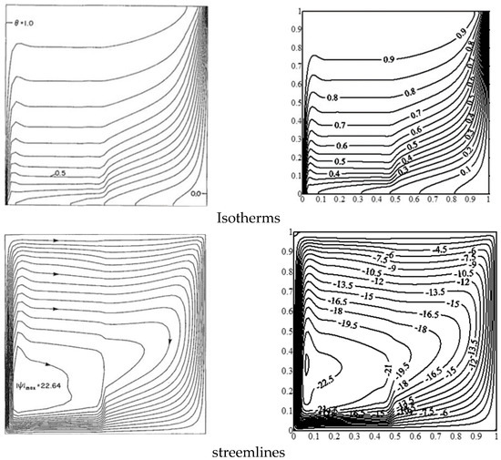
Figure 2.
Comparison of the current results (right) and those of [43] (left).
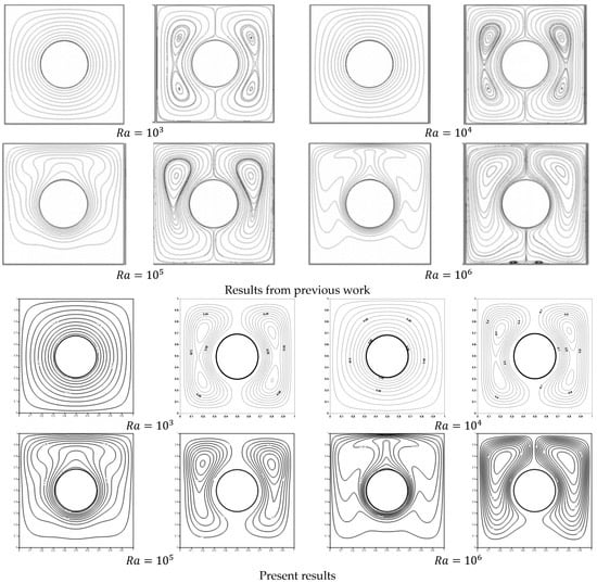
Figure 3.
Comparison of isothermal lines and streamlines for four different Rayleigh numbers from [44] and the present work.
3. Results and Discussion
In this work, the outcomes of the various thermophysical parameters, such as the inner shapes (, Rayleigh number , porosity (), and Darcy number were analyzed. Addition of nanoparticles was limited to 0.05 because more than 5% of the volume of the nanoparticle fraction can cause sedimentation and absorption of nanoparticles within a porous medium [45,46]. Pure water was used in this research, so was adopted. At the top/bottom of the cavity, two hot inner superellipse shapes were placed. Figure 4 illustrates the streamlines resulting from the shape of two inner superellipses , porosity , Rayleigh number , and Darcy number , respectively. The streamlines became parallel to each other, taking the shape of the inner superellipse as increased, and we noted that the streamlines contracted around the inner superellipses shapes as increased. The stream function decreased by 0.99% as increased from 0.2 to 0.8 because of porosity. The third section of the Figure 4 depicts various values of the Rayleigh number at (). The contours of the streamlines were extended across the cavity as the Raleigh number grew, demonstrating that increasing the Raleigh number enhanced the buoyancy force and thus the movement of the nanofluid. However, as Ra increased, the strength of the flow circulation increased dramatically and the structure of the flow circulation expanded in size, occupying most of the enclosure. Furthermore, at , the absolute value of stream function reached its maximum value ().
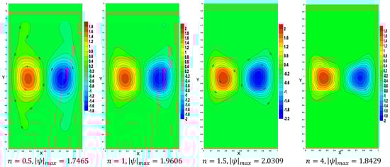
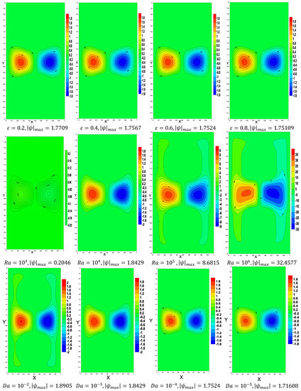
Figure 4.
The streamlines below the variations of the shape of superellipse enclosures, porosity, Rayleigh number, and Darcy number, respectively.
The fourth section of Figure 4 illustrates the impact of the Darcy number on fluid flow inside the enclosure when porosity . The porous resistance increased as decreased from to , providing a slowing of the movement of the nanofluid ( decreased) within the porous layers.
The effects of the inner superellipse shapes, porosity, Rayleigh number, and Darcy number on the dimensionless temperature distribution are represented in Figure 5. It was detected that as increased (the changes in the shape of the inner superellipse), the isothermal lines increased around the inner shapes and thus the heat transport was boosted. At , the top area of the cavity became hotter and the bottom became colder. The isothermal lines had slight changes according to the variations in and .
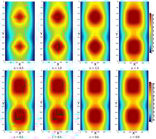
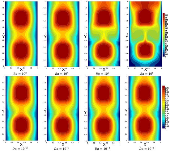
Figure 5.
The temperature below the variations of the shape of superellipse enclosures, porosity, Rayleigh number, and Darcy number.
Figure 6 shows the impacts of Rayleigh and Darcy numbers on horizontal and vertical velocities, temperature profiles, and the mean . As the porous resistance increased, the mean Nu decreased.
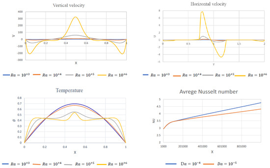
Figure 6.
The horizontal and vertical velocities, temperature below the influences of , and mean below the influences of D.
The vertical velocity near , the cavity’s center, along the axis, increased as was augmented. The horizontal velocity at , the cavity’s center, along the axis changed slightly at the bottom area and at the top area , and had the highest values at . The presence of hot inner shapes caused a high temperature inside the cavity, which caused the formation of vortices in the cavity’s center and, as a result, higher velocity values. We observed an opposite connection between the temperature and Rayleigh number in the cavity’s center, and a proportional relationship between them on the cavity’s left () and right (). The reason relates to the expansion of the isothermal lines from the center across the cavity’s sides as increased. Physically, Ra increases the buoyancy force, which sped up nanofluid movements and improved heat transfer in the cavity. The porous resistance increased as the Darcy number decreased from to , raising the average Nusselt number. Figure 7 shows the effects of the shape of superellipse enclosures and the nanofluid volume fraction on the average Nusselt number. We observed that the average Nusselt was heavily reliant on both. The insertion of Cu-water nanoparticles into the base fluid increased the heat transfer coefficient, as evidenced by the average Nusselt number, which rose significantly with increasing nanoparticle volume fraction.
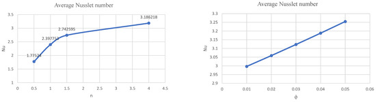
Figure 7.
The average Nusselt number below the influences of .
The impacts of inner superellipse shape on vertical velocities and temperature profiles are shown in Figure 8. Overall, increasing the area of the inner shape obviously raised the temperature and slightly raised the vertical velocity.
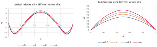
Figure 8.
The influence of an inner superellipse shape enclosures on the vertical velocities and temperature profiles.
4. Conclusions
In this paper, using the FVM method, we scrutinized the influences of superellipse inner shapes on the nanofluid movements in a non-Darcy porous cavity. The hot superellipse inner shapes were placed at the cavity’s bottom and top. The cavity’s boundary conditions were considered as adiabatic boundaries on the top and bottom. The investigations led to the following conclusions:
- The flow and temperature were strongly affected as the shape of the inner superellipse grew larger.
- The average Nusselt number grew sharply with increasing nanoparticle volume fraction, which means that introducing Cu-water nanoparticles into the base fluid increased the heat transfer coefficient.
- The buoyancy force, and hence the movement of the nanofluid, increased as the Rayleigh number grew, and an inverse relationship existed between the temperature and Rayleigh number in the cavity’s core.
- As decreased, the porous resistance increased, limiting the nanofluid’s movement within the porous layers. The mean was shown to decrease as the porous resistance increased (.
In a future study, we will conduct analysis of entropy generation in nanofluid flow due to double diffusive MHD mixed convection in a lid-driven cavity with a superellipse inner shapes.
Funding
This research received no external funding.
Institutional Review Board Statement
Not applicable.
Informed Consent Statement
Not applicable.
Data Availability Statement
Not applicable.
Acknowledgments
This research was funded by the Deanship of Scientific Research at Princess Nourah bint Abdulrahman University through the Fast-track Research Funding Program.
Conflicts of Interest
The author declares no conflict of interest.
Nomenclature
| Rayleigh number | ||
| specific heat (J/g·C) | ||
| Darcy number | ||
| average particle size | ||
| Forchheimer coefficient | ||
| gravitational acceleration | ||
| H | dimensionless height of porous layer | |
| dimensional height of porous layer | ||
| permeability (m2) | ||
| thermal conductivity (W/m·K) | ||
| thermal conductivity of pure fluid | ||
| thermal conductivity of porous matrix | ||
| thermal conductivity of nanofluid | ||
| thermal conductivity of dispersed nanoparticles | ||
| Ergun’s constant | ||
| average particle size of the bed | ||
| Nusselt number | ||
| average Nusselt number | ||
| pressure (N/m2) | ||
| Prandtl number | ||
| cavity length (m) | ||
| temperature (K) | ||
| dimension velocity components (m/s) | ||
| dimensionless velocity components | ||
| Cartesian coordinates (m) | ||
| dimensionless coordinates | ||
| Greek symbols | ||
| viscosity (kg/m·s) | ||
| thermal diffusivity | ||
| thermal expansion coefficient | ||
| volumetric thermal expansion | ||
| porosity | ||
| solid volume fraction | ||
| kinematic viscosity (m2/s) | ||
| density (kg/m3) | ||
| stream function | ||
| dimensionless temperature | ||
| Subscripts | ||
| fluid | ||
| nanofluid | ||
| porous medium | ||
| c | cold | |
| h | hot | |
References
- Chen, Z.; Huan, G.; Ma, Y. Computational methods for multiphase flows in porous media. In Society for Industrial and Applied Mathematics; SIMA Publication: Philadelphia, PA, USA, 2006. [Google Scholar]
- Marcelo, J.S.d.L. Turbulence in Porous Media: Modeling and Applications; Elsevier: Boston, MA, USA, 2012. [Google Scholar]
- Donald, A.N.; Adrian, B. Convection in Porous Media, 4th ed.; Springer: New York, NY, USA, 2013. [Google Scholar]
- Diersch, H.-J.G.A. FEFLOW: Finite Element Modeling of Flow, Mass and Heat Transport in Porous and Fractured Media; Springer: Berlin, Germany, 2014. [Google Scholar]
- Alloui, Z.; Rebhi, R.; Mamou, M.; Vasseur, P. Effects of quadratic drag on natural convection in a tilted porous layer with uniform heat flux from the side. Int. J. Heat Mass Transf. 2017, 115, 314–325. [Google Scholar] [CrossRef]
- Dixon, J.; Kulacki, F. Mixed convection in fluid superposed porous layers. Part 2: Experiments. Int. J. Heat Mass Transf. 2017, 109, 1301–1306. [Google Scholar] [CrossRef]
- Astanina, M.S.; Sheremet, M.A.; Oztop, H.F.; Abu-Hamdeh, N. MHD natural convection and entropy generation of ferrofluid in an open trapezoidal cavity partially filled with a porous medium. Int. J. Mech. Sci. 2018, 136, 493–502. [Google Scholar] [CrossRef]
- Cho, C.-C.; Yau, H.-T.; Chen, C.-K. Enhancement of natural convection heat transfer in a U-shaped cavity filled with Al2O3-water nanofluid. Therm. Sci. 2012, 16, 1317–1323. [Google Scholar] [CrossRef]
- Esfe, M.H.; Arani, A.A.A.; Yan, W.-M.; Aghaei, A. Natural convection in T-shaped cavities filled with water-based suspensions of COOH-functionalized multi walled carbon nanotubes. Int. J. Mech. Sci. 2017, 121, 21–32. [Google Scholar] [CrossRef]
- Bhowmick, S.; Xu, F.; Zhang, X.; Saha, S.C. Natural convection and heat transfer in a valley shaped cavity filled with initially stratified water. Int. J. Therm. Sci. 2018, 128, 59–69. [Google Scholar] [CrossRef]
- Teixeira, F.B.; Pereira, M.S.; Feijoó, B.C.; Rocha, L.A.O.; Isoldi, L.A.; Santos, E.D. Geometric Evaluation of T And H-Shaped Cavities Inserted in A Solid With Heat Generation Applying Constructal Design. Rev. Eng. Térmica 2017, 16, 89–95. [Google Scholar] [CrossRef]
- Mikhail, A.S.; Ioan, P.; Baytas, A.C. Non-equilibrium natural convection in a differentially-heated nanofluid cavity partially filled with a porous medium. Int. J. Numer. Methods Heat Fluid Flow 2019, 29, 2524–2544. [Google Scholar]
- Sreedevi, P.; Reddy, P.S. Effect of magnetic field and thermal radiation on natural convection in a square cavity filled with TiO2 nanoparticles using Tiwari-Das nanofluid model. Alex. Eng. J. 2021, in press. [Google Scholar] [CrossRef]
- Ma, Y.; Mohebbi, R.; Yang, Z. Simulation of Nanofluid Natural Convection in a U-Shaped Cavity Equipped by a Heating Obstacle: Effect of Cavity’s Aspect Ratio. J. Taiwan Inst. Chem. Eng. 2018, 93, 263–276. [Google Scholar] [CrossRef]
- Rahimi, A.; Sepehr, M.; Lariche, M.J.; Mesbah, M.; Kasaeipoor, A.; Malekshah, E.H. Analysis of natural convection in nanofluid-filled H-shaped cavity by entropy generation and heatline visualization using lattice Boltzmann method- Experimental thermo-physical properties of nanofluid. Phys. E Low-Dimens. Syst. Nanostruct. 2017, 97, 347–362. [Google Scholar] [CrossRef]
- Izadi, M.; Mohebbi, R.; Karimi, D.; Sheremet, M.A. Numerical Simulation of Natural Convection Heat Transfer inside a Shaped Cavity Filled by a MWCNT-Fe3O4/Water Hybrid Nanofluids using LBM. Chem. Eng. Process. Process. Intensif. 2018, 125, 108467. [Google Scholar] [CrossRef]
- Ahmed, S.E.; Mansour, M.; Alwatban, A.M.; Aly, A. Finite element simulation for MHD ferro-convective flow in an inclined double-lid driven L-shaped enclosure with heated corners. Alex. Eng. J. 2020, 59, 217–226. [Google Scholar] [CrossRef]
- Sheremet, M.A.; Pop, I. Natural Convection in a Square Porous Cavity with Sinusoidal Temperature Distributions on Both Side Walls Filled with a Nanofluid: Buongiorno’s Mathematical Model. Transp. Porous Media 2014, 105, 411–429. [Google Scholar] [CrossRef] [Green Version]
- Boulahia, Z.; Wakif, A.; Sehaqui, R. Modeling of Free Convection Heat Transfer Enhancement Utilizing Nanofluid Inside A Wavy Wal Enclosure with A Pair Of Hot And Cold Cylinders. Front. Heat Mass Transf. 2017, 8, 1–10. [Google Scholar] [CrossRef] [Green Version]
- Davis, G.D.V. Natural convection of air in a square cavity: A bench mark numerical solution. Int. J. Numer. Methods Fluids 1983, 3, 249–264. [Google Scholar] [CrossRef]
- Szewc, K.; Pozorski, J.; Tanière, A. Modeling of natural convection with Smoothed Particle Hydrodynamics: Non-Boussinesq formulation. Int. J. Heat Mass Transf. 2011, 54, 4807–4816. [Google Scholar] [CrossRef]
- Srinivasacharya, D.; Ramreddy, C.; Naveen, P. Effects of nonlinear Boussinesq approximation and double dispersion on a micropolar fluid flow under convective thermal condition. Heat Transf. Asian Res. 2018, 48. [Google Scholar] [CrossRef] [Green Version]
- Ahmed, S.E.; Alrowaili, D.; Mohamed, E.M.; Aly, A.M. Nanofluid Flows within Porous Enclosures Using Non-Linear Boussinesq Approximation. Comput. Mater. Contin. 2021, 66, 3195–3213. [Google Scholar] [CrossRef]
- Hajipour, M.; Dehkordi, A.M. Analysis of nanofluid heat transfer in parallel-plate vertical channels partially filled with porous medium. Int. J. Therm. Sci. 2012, 55, 103–113. [Google Scholar] [CrossRef]
- Mahian, O.; Kianifar, A.; Kleinstreuer, C.; Al-Nimr, M.A.; Pop, I.; Sahin, A.Z.; Wongwises, S. A review of entropy generation in nanofluid flow. Int. J. Heat Mass Transf. 2013, 65, 514–532. [Google Scholar] [CrossRef]
- Bourantas, G.; Skouras, E.; Loukopoulos, V.; Burganos, V. Heat transfer and natural convection of nanofluids in porous media. Eur. J. Mech. B/Fluids 2014, 43, 45–56. [Google Scholar] [CrossRef]
- Sheremet, M.; Groşan, T.; Pop, I. Steady-state free convection in right-angle porous trapezoidal cavity filled by a nanofluid: Buongiorno’s mathematical model. Eur. J. Mech. B/Fluids 2015, 53, 241–250. [Google Scholar] [CrossRef]
- Jmai, R.; Ben-Beya, B.; Lili, T. Heat transfer and fluid flow of nanofluid-filled enclosure with two partially heated side walls and different nanoparticles. Superlattices Microstruct. 2013, 53, 130–154. [Google Scholar] [CrossRef]
- Chamkha, A.J.; Ismael, M. Natural Convection in Differentially Heated Partially Porous Layered Cavities Filled with a Nanofluid. Numer. Heat Transf. Part. A Appl. 2014, 65, 1089–1113. [Google Scholar] [CrossRef]
- Al-Zamily, A.M.J. Analysis of natural convection and entropy generation in a cavity filled with multi-layers of porous medium and nanofluid with a heat generation. Int. J. Heat Mass Transf. 2017, 106, 1218–1231. [Google Scholar] [CrossRef]
- Khan, S.A.; Khan, M.I.; Hayat, T.; Javed, M.F.; Alsaedi, A. Mixed convective non-linear radiative flow with TiO2-Cu-water hybrid nanomaterials and induced magnetic field. Int. J. Numer. Methods Heat Fluid Flow 2019, 29, 2754–2774. [Google Scholar] [CrossRef]
- Sparrow, E.M.; Chrysler, G.M.; Azevedo, L.F. Observed Flow Reversals and Measured-Predicted Nusselt Numbers for Natural Convection in a One-Sided Heated Vertical Channel. J. Heat Transf. 1984, 106, 325–332. [Google Scholar] [CrossRef]
- Stefanizzi, P.; Lippolis, A.; Liuzzi, S. Experimental and Numerical Analysis of Heat Transfer in The Cavities of Hollow Blocks. Int. J. Heat Technol. 2013, 31, 149–154. [Google Scholar] [CrossRef]
- Qian, X.; Lee, S.; Yang, Y. Heat Transfer Coefficient Estimation and Performance Evaluation of Shell and Tube Heat Exchanger Using Flue Gas. Processes 2021, 9, 939. [Google Scholar] [CrossRef]
- Kladias, N.; Prasad, V. Experimental verification of Darcy-Brinkman-Forchheimer flow model for natural convection in porous media. J. Thermophys. Heat Transf. 1991, 5, 560–576. [Google Scholar] [CrossRef]
- Alzahrany, M.; Kiwan, S. Mixed Convection Heat Transfer in the Annulus between Two Concentric Vertical Cylinders Using Porous Layers. Transp. Porous Media 2009, 76, 391–405. [Google Scholar] [CrossRef]
- Nguyen, M.T.; Aly, A.; Lee, S.-W. Natural Convection in a Non-Darcy Porous Cavity Filled with Cu–Water Nanofluid Using the Characteristic-Based Split Procedure in Finite-Element Method. Numer. Heat Transf. Part. A Appl. 2014, 67, 224–247. [Google Scholar] [CrossRef]
- Wang, L.; Zhang, D.-D.; Zhao, F.-Y.; Liu, D.; Wang, H.-Q. Thermal driven flows inside a square enclosure saturated with nanofluids: Convection heat functions and transfer rate revisions from a homogenous model. Numer. Heat Transf. Part. B Fundam. 2019, 75, 265–288. [Google Scholar] [CrossRef]
- Ho, C.-J.; Huang, C.-Y.; Lai, C.-M. Heat Transfer by Natural Convection in a Square Enclosure Containing PCM Suspensions. Energies 2021, 14, 2857. [Google Scholar] [CrossRef]
- Nithiarasu, P.; Seetharamu, K.; Sundararajan, T. Natural convective heat transfer in a fluid saturated variable porosity medium. Int. J. Heat Mass Transf. 1997, 40, 3955–3967. [Google Scholar] [CrossRef]
- Maxwell, J.C. A Treatise on Electricity and Magnetism; Clarendon Press: Oxford, UK, 1904; Volume 1. [Google Scholar]
- Brinkman, H.C. The Viscosity of Concentrated Suspensions and Solutions. J. Chem. Phys. 1952, 20, 571–581. [Google Scholar] [CrossRef]
- Beckermann, C.; Ramadhyani, S.; Viskanta, R. Natural Convection Flow and Heat Transfer Between a Fluid Layer and a Porous Layer Inside a Rectangular Enclosure. J. Heat Transf. 1987, 109, 363–370. [Google Scholar] [CrossRef]
- Kim, B.; Lee, D.; Ha, M.; Yoon, H. A numerical study of natural convection in a square enclosure with a circular cylinder at different vertical locations. Int. J. Heat Mass Transf. 2008, 51, 1888–1906. [Google Scholar] [CrossRef]
- Ghazvini, M.; Shokouhmand, H. Investigation of a nanofluid-cooled microchannel heat sink using Fin and porous media approaches. Energy Convers. Manag. 2009, 50, 2373–2380. [Google Scholar] [CrossRef]
- Muthtamilselvan, M.; Kandaswamy, P.; Lee, J. Heat transfer enhancement of copper-water nanofluids in a lid-driven enclosure. Commun. Nonlinear Sci. Numer. Simul. 2010, 15, 1501–1510. [Google Scholar] [CrossRef]
Publisher’s Note: MDPI stays neutral with regard to jurisdictional claims in published maps and institutional affiliations. |
© 2021 by the author. Licensee MDPI, Basel, Switzerland. This article is an open access article distributed under the terms and conditions of the Creative Commons Attribution (CC BY) license (https://creativecommons.org/licenses/by/4.0/).