Abstract
The reduction of unwanted heat losses across the buildings’ envelope is very relevant to increase energy efficiency and achieve the decarbonization goals for the building stock. Two major heat transfer mechanisms across the building envelope are conduction and radiation, being this last one very important whenever there is an air cavity. In this work, the use of aerogel thermal break (TB) strips and aluminium reflective (AR) foils are experimentally assessed to evaluate the thermal performance improvement of double-pane lightweight steel-framed (LSF) walls. The face-to-face thermal resistances were measured under laboratory-controlled conditions for sixteen LSF wall configurations. The reliability of the measurements was double-checked making use of a homogeneous XPS single panel, as well as several non-homogeneous double-pane LSF walls. The measurements allowed us to conclude that the effectiveness of the AR foil is greater than the aerogel TB strips. In fact, using an AR foil inside the air cavity of double-pane LSF walls is much more effective than using aerogel TB strips along the steel flange, since only one AR foil (inner or outer) provides a similar thermal resistance increase than two aerogel TB strips, i.e., around +0.47 m2∙K/W (+19%). However, the use of two AR foils, instead of a single one, is not effective, since the relative thermal resistance increase is only about +0.04 m2∙K/W (+2%).
1. Introduction
The most relevant energy consumer in European Union (EU) is the buildings’ sector [1]. In fact, during 2019, forty percent of the EU27 final energy consumption was spent in buildings [2]. Within this share, almost 50% are used for space heating and cooling [1]. These facts are related to reduced energy efficiency of buildings and consequent wasted energy. Indeed, in the EU three out of four buildings are classified as inefficient [2]. To make Europe’s building sector compatible with the Paris Agreement, two goals need to be achieved: (1) reduce energy demand through energy efficiency measures, and; (2) increase the use of renewable energy sources [3].
As is well known [4], the reduction of undesirable heat losses is one of the possible strategies to improve energy efficiency. This heat loss reduction could be achieved by mitigating each heat transfer mechanism across the building envelope: radiation, convection, and conduction. The most forthright and simplest approach to increase the thermal resistance of building envelope components is the usage of thermal insulation, reducing significantly the heat transfer by conduction. Nevertheless, the effectiveness of the thermal insulation depends also on their position within the building element, as previously demonstrated by Roque and Santos [5]. Additionally, this insulation material also endorses sound insulation, principally when porous batt insulation materials are used inside the air cavities [6].
Currently, extremely efficient insulation materials (sometimes designated by SIMs—super insulating materials) are emerging in the market, having very small thermal conductivities [7]. Aerogels [8] and vacuum insulating panels (VIPs) [9] are nowadays two of the most common examples of SIMs. Notice that increasing discontinuous thermal insulation along building envelopes may rise the relevance of thermal bridges, being this effect even more significant in steel structures, given the huge thermal conductivity of steel [10]. In fact, as concluded by Erhorn-Klutting and Erhorn [11] up to near one-third of the heating energy needs could be originated by thermal bridges in traditional buildings (reinforced concrete and masonry).
During the last years, the lightweight steel frame (LSF) construction system is being more used, mainly for low-rise residential houses [12], due to their intrinsic benefits. Some of these advantages are: fast construction, high mechanical strength, and low weight, high potential for recycling and reuse, reduced on-site disruption, great suitability for retrofitting, high architectural flexibility, economical transportation and handling, easy prefabrication, precise tolerances, superior quality, insect damage resistance, and humidity stability shape [4].
Nowadays, several techniques could be used to mitigate thermal bridges in LSF buildings’ elements, such as slotted thermal steel studs [13,14,15], thermal break (TB) strips [13,16,17], and continuous thermal insulation layers (e.g., ETICS—external thermal insulation composite system) [18,19,20]. Moreover, the steel frame is so important that even minor changes in the stud flanges shape and size could have a relevant effect on the thermal performance of LSF walls [21].
Moreover, when there is an air cavity inside the wall, one effective way to improve the thermal performance is by reducing the heat transfer by radiation. This could be achieved by using reflective low-emissivity paint or foil inside the air gaps of the building components [22,23]. This thermal performance improvement solution has supplementary benefits, such as easy installation and low cost.
As recently mentioned by Bruno et al. [23], there is a very small number of research works related to thermal resistance improvement due to low-emissivity materials placed inside air cavities. This fact is even more perceptible in LSF double-pane building elements.
Recently, Santos and Ribeiro [24] studied the thermal performance of double-pane lightweight steel-framed walls with and without a reflective foil. This assessment was mainly experimental under laboratory-controlled conditions, but the measurements were compared with 2D finite element numerical simulations. Several air cavity thicknesses (0 mm up to 50 mm, with an increment of 10 mm) were evaluated, but only one aluminium reflective (AR) foil was considered (on the outer surface of the air cavity). It was concluded that “the use of a reflective foil is a very effective way to increase the thermal resistance of double pane LSF walls, without increasing the wall thickness and weight”. However, when using an AR foil, it is not worthy to have an air cavity higher than 30 mm. One research gap that was not investigated in this work was if it is worthy to use two low-emissivity aluminium foils (one in each air-gap surface). Moreover, another interesting question is if the performance of the AR foil is similar when used in the outer or inner surface of the air cavity.
Regarding the use of TB strips, there is also a lack of scientific research works available. Perhaps the most relevant is the experimental campaign completed by Santos and Mateus [17] for the assessment of thermal break strip performance in load-bearing and non-load-bearing LSF walls. They concluded that an outer or inner TB strip has very similar thermal performances, being the best performance achieved for two TB strips (one on each steel stud flange) and for the aerogel TB strip material. Notice that these walls were single-pane LSF walls, not found in the literature any research work related with the use of TB strips in double-pane LSF walls, or in combined use with AR foils.
In this work, the authors seek the answers for some of these research gaps and questions, by assessing the thermal performance improvement of double-pane LSF walls using thermal break strips and reflective foils. The strategy was to start with a reference double-pane LSF wall (30 mm air gap) and compare the thermal resistance increase only due to aerogel TB strips and only due to AR foils, by performing measurements under laboratory-controlled conditions. Moreover, on the next set of measurements, the combined effect of both aerogel TB strips, and AR foils was evaluated. Notice that the aerogel was selected as the material for the TB strips since it is one of the highest performant materials available in the market, having a very reduced thermal conductivity (in this case, 0.015 W/m K). Moreover, aluminium was selected as the material for the reflective foil since it is the most currently used for this purpose, having a very reduced emissivity value (below 0.05).
This article is structured as follows. After this small introduction and contextualization, it is presented a section with the materials and methods, where the LSF walls and used materials are characterized. Moreover, the experimental lab tests are described, including the experimental setup, as well as the set-points and test procedures. Additionally, to ensure the reliability of the measurements and to check the test procedures, two verifications were performed: (1) comparison between the measured thermal conductivity of a homogeneous XPS panel with the value provided by the manufacturer, and; (2) comparison between the measured thermal resistance of four double-pane LSF walls, namely: (1) reference; (2) with a single TB strip; (3) with a single AR foil, and; (4) with both two TB strips and two AR foils, with the predictions provided by numerical simulation models. The obtained results are presented and discussed next, being grouped into three sets: (1) only TB strips; (2) only AR foils; (3) combined TB strips and AR foils. Finally, the main conclusions of this research work are summarized. Notice, that the various scenarios evaluated in this research work were based on previous papers from authors, namely reference [24] for the aluminium reflective foil scenarios and reference [17] for the thermal break strips.
2. Materials and Methods
In this section, the tested double-pane LSF walls are described, and the respective materials are characterized. Furthermore, the explanation about the lab tests is performed, through the presentation of the experimental setup and the description of the test procedures. Finally, to ensure the accuracy and reliability of the achieved experimental results, the test procedures are verified using numerical simulation results for comparison.
2.1. Walls and Materials Characterization
A representative horizontal cross-section of the reference double-pane LSF wall used in the lab tests is displayed in Figure 1. The frame structure of each LSF wall pane is composed of steel studs (C48 × 37 × 4 × 0.6 mm) spaced 400 mm apart and filled with mineral wool (MW) panels with a thickness of 48 mm. The LSF wall panes are separated by a 30 mm thick air cavity and its most superficial layers are made up of two gypsum plasterboards (GPB) panels with a total thickness of 25 mm, on each side.
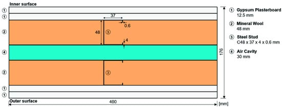
Figure 1.
Geometry and materials of the reference double-pane LSF wall: horizontal cross-section.
The thickness and the thermal conductivities of the materials that composed the reference double-pane LSF wall used in the experimental tests are displayed in Table 1.

Table 1.
Reference double-pane LSF wall materials, thickness (d), and thermal conductivities (λ).
In this research work, the thermal performance improvement due to thermal break (TB) strips and/or reflective foils was experimentally evaluated. The TB strips tested are 50 mm wide and 10 mm thick, and the material used was aerogel with thermal conductivity of 0.015 W/(m·K) [16]. Three configurations for the localization of the TB strips were considered (Figure 2): (i) along the inner steel stud flange (inner wall pane); (ii) along the outer steel stud flange (outer wall pane); (iii) on both steel stud flanges. Furthermore, the reflective foils tested are made of aluminium with an emissivity equal to 0.05 [23,24].
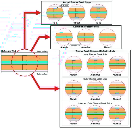
Figure 2.
Wall configurations tested using aerogel thermal break (TB) strips and aluminium reflective foils.
Regarding the localization of the reflective foils, three configurations were considered (Figure 2): (i) along the inner side of the air cavity; (ii) along the outer side of the air cavity; (iii) along both sides of the air cavity. These two elements (aerogel TB strips and aluminium reflective foils) were tested separately, as well as combined, resulting in a total of fifteen wall configurations, as schematically illustrated in Figure 2.
2.2. Experimental Lab Tests
2.2.1. Experimental Setup
The lab measurements were performed using a mini hot box apparatus, as illustrated in Figure 3a. This equipment is composed of two climatic chambers: (i) a hot box heated by an electric resistance; (ii) a cold box cooled by a refrigerator. The double-pane LSF wall test sample was placed between these two chambers, as displayed in Figure 3b,c. To minimize the amount of heat that is lost through the lateral surfaces of the sample, its perimeter was covered with 80 mm thick polyurethane foam insulation (Figure 3a).
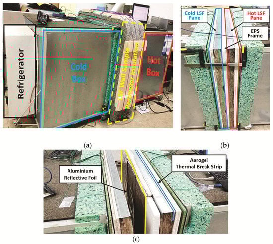
Figure 3.
Mini hot box apparatus: (a) global view of the equipment; (b) LSF wall test sample; (c) LSF wall test sample with TB strips and a reflective foil.
The air cavity within the test frame was ensured by using a 30 mm thick EPS frame, separating the two LSF wall panes (Figure 3b,c), whose edges match the thickness of the thermal insulation of the climatic chambers’ envelope (Figure 4b). The frontal view of the LSF wall pane (hot side) is displayed in Figure 4a, where it is possible to visualize the steel structure constituted by three vertical studs and filled with mineral wool. Despite the three vertical studs, when the sample is placed in the mini hot box apparatus, only the central stud is exposed to the temperature gradient provided by the climatic chambers. Figure 4b illustrates the EPS frame and the respective dimensions of its edges, as well as the aluminium reflective foil localization (in this case, on the hot side). The aerogel TB strips were applied covering all the steel profiles of the test sample (three vertical studs and two horizontal tracks), as displayed in Figure 4c. Inside each climatic chamber, small interior fans were used to promote internal air circulation and reduce the probability of air temperature stratification. Furthermore, on each side of the LSF wall sample (hot and cold), a black radiation shield was placed 10 cm apart from the wall surface.
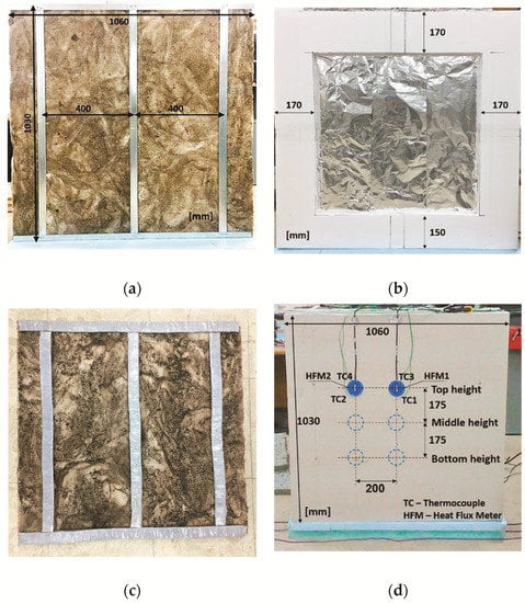
Figure 4.
Double-pane LSF wall test sample: (a) LSF wall pane (hot side); (b) EPS frame and reflective foil; (c) aerogel TB strip; (d) arrangement of the monitoring system (cold side).
The arrangement of the monitoring system, constituted by heat flux meters (HFM) and thermocouples (TCs), is displayed in Figure 4d. To measure the heat flux through the test sample, four heat flux meters (Hukseflux model HFP01, precision: ±3%) were used, being two of them applied on the hot wall surface and another two on the cold wall surface. On each wall surface, since the LSF wall sample presents two distinct thermal behaviour zones, two locations for the heat flux meters were considered: (i) nearby the central vertical steel stud (HFM1); (ii) in the middle of the insulation cavity (HFM2).
Temperature measurements were performed using twelve type K (1/0.315) PFA insulated thermocouples (TCs), certified with class 1 precision. These TCs were calibrated within the temperature range [5 °C; 45 °C], with a 5 °C increment, by immersing them in a thermostatic stirring water bath (Heto CB 208). The measurements were performed using six TCs on each side of the wall sample, considering the following configuration: two of them measured the wall surface temperature (TC1 and TC2), another two measured the air temperature between the radiation shield and the wall surface (TC3 and TC4), and the remaining two measured the environment air temperature inside the climatic chamber (TC5 and TC6).
The temperature and heat flux data measured during each test were recorded using one PICO TC-08 data logger (precision ±0.5 °C), on each side of the wall test sample (hot and cold). The management of the data recorded was performed by connecting the two data loggers to a laptop and using the PicoLog version 6.1.10 software. In Table 2, the equipment used in the lab measurements is characterized in terms of brand, model, measurement range, and precision.
Table 2.
Characteristics of the measurement equipment used in the lab experiments.
2.2.2. Set-Points and Test Procedures
The thermal performance of the double-pane LSF test samples was evaluated using the heat flux meter (HFM) method, adapted to measure, simultaneously, at both wall surfaces (hot and cold), as suggested by Rasooli and Itard [28]. Comparatively to the measurement on only one side (as prescribed by ISO 9869-1 [29]), the measurement at both wall surfaces allows to increase the precision and reduce the test duration. Regarding set-point temperatures, the values of 40 °C and 5 °C were programmed for the hot and cold boxes, respectively, being the measurements performed in a quasi-steady-state heat transfer condition.
The minimum duration of each experimental test performed was 24 h and the measurements were recorded at each 10 s. This recorded data was averaged to hourly values, allowing to obtain the hourly thermal resistance (-value). Following the convergence criteria prescribed in ASTM C1155-95 [30], only the estimated hourly R-values with an absolute difference, in relation to the previous value, lower than 10% were considered in the measurements.
The application of the HFMs in two locations on the test sample with different thermal behaviour, allows the determination of two distinct conductive local R-values: (1) a lower value in the central vertical steel stud zone (Rstud); (2) a higher value in the middle of the insulation cavity zone (Rcav). The overall surface-to-surface value of the wall is calculated using an area-weighted average of these two conductive local R-values. Furthermore, for each wall sample, three tests were performed to ensure the repeatability of the measurements. The three tests correspond to three high locations (top, middle, and bottom), as illustrated in Figure 4d, and the measured overall conductive R-value of the LSF wall was considered equal to the average of these three tests.
2.3. Numerical Simulations
These numerical simulations were performed making use of bidimensional models built in the THERM [31] finite elements software. The main idea was to compare the measured conductive -values with the results provided by these simulations, as presented later in Section 2.4.2. In these models, only a representative part of the double-pane LSF walls (400 mm wide) were simulated, as previously illustrated in Figure 1 for the reference LSF wall. The thermal conductivities of the materials used in these numerical simulations were previously displayed in Table 1. The finite element mesh was refined to achieve a maximum 3% error in these computations and the mesh void tolerance was 1 mm2. The maximum number of iterations was 100 and the used quad-tree mesh parameter was set to 6, while the convergence tolerance was equal to 1 × 10⁻⁶. Using this mesh configuration, the maximum number of finite elements was 15,429.
Regarding the boundary conditions, the air temperature was set to 5 °C and 40 °C, for the outer and inner environments, respectively. Notice that these values are equal to the set-points defined for cold and hot boxes, as previously described in Section 2.2.2.
Furthermore, the surface thermal resistances were modelled using the average values measured for each LSF wall surface and for each test, considering the air and surface temperature differences and the surface heat fluxes. The measured surface thermal resistances vary within the interval [0.06; 0.13] m2·K/W, thereby respecting the range defined by EN ISO 6946 [32] for horizontal heat flow, i.e., between 0.04 m2·K/W for external surface resistance (se) and 0.13 m2·K/W for internal surface resistance (si).
In a previous work, a similar procedure was implemented for a double-pane LSF wall with and without one AR foil for different air cavity thicknesses [24]. Regarding the simulation of unventilated airspaces, it was concluded that both “CEN simplified“ and “NFRC 100” models were able to reproduce with reasonable accuracy (around ±5%) the thermal behaviour of the air cavities. However, for larger thicknesses of the air cavities (greater than 20 mm) the “CEN simplified” model exhibited a better accuracy. Thus, in the present work, this calculation model was selected since the air cavity was 30-mm thick.
2.4. Verification of the Test Procedures and Measured Values
The authors already have a large experience in measuring the thermal performance of LSF walls under controlled laboratory conditions [17,19,21,24,33]. Nevertheless, some verifications were performed to check the test procedures and ensure the reliability of the measured values, as briefly explained in the next two subsections.
2.4.1. Homogeneous XPS Panel
The first verification was made using a homogenous XPS panel (Topox® Cuber SL), having a thermal conductivity of 0.034 W/(m·K) and a thickness of 60 mm, which were tested under the same conditions of the evaluated double-pane LSF walls. It was measured an XPS conductive thermal resistance equal to 1.748 m2·°C/W. Knowing the XPS panel thickness, easily it was computed the laboratory-measured thermal conductivity, which is equal to the value provided by the manufacturer, ensuring this way the good accuracy and working conditions of the data acquisition system and sensors.
2.4.2. Nonhomogeneous Double-Pane LSF Walls
Besides the previous verification for a homogeneous XPS panel with known thermal conductivity, it was performed another set of accuracy confirmation tests for some of the double-pane LSF walls assessed, since they are very heterogeneous regarding their thermal properties (e.g., mineral wool and steel).
Thus, besides the reference LSF wall without any thermal break (TB) strip nor aluminium reflective (AR) foil, additional selections included an LSF wall with one aerogel TB strip, a LSF wall with a single AR foil, and another LSF wall containing two TB strips (inner and outer) as well as double AR foils (inner and outer), embracing in this way the two thermal performance improvement strategies and a combined LSF wall configuration.
The measured thermal resistances of the four representative double-pane LSF walls are displayed in Table 3, as well as the -values predicted by the THERM [31] bi-dimensional models (see previous Section 2.3). The differences between the measured and the predicted thermal resistances range from −0.059 m2·K/W (−2%) and +0.062 m2·K/W (+3%). Given all the simulation and experimental uncertainties involved, this comparison denotes a very good agreement between measurements and numerical simulations. Therefore, it was concluded that the implemented test procedures are adequate and the measured values are reliable.
Table 3.
Predicted and measured conductive thermal resistance of double-pane LSF walls. Absolute and percentage differences.
Besides the -values comparison previously displayed in Table 3, an additional verification was performed making use of the finite elements THERM models, as illustrated in Figure 5. These plots exhibit the predicted heat flux distribution along the cross-section of four double-pane LSF walls formerly presented in Table 3.
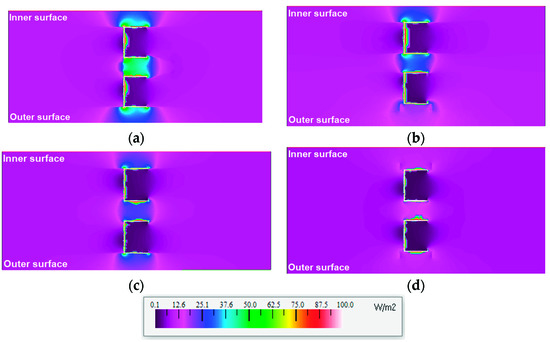
Figure 5.
Predicted heat flux distribution within the LSF walls’ cross-section: (a) reference LSF wall; (b) outer TB strip; (c) outer AR foil; (d) double TB strips and AR foils.
In Figure 5a, the higher heat flux is very well visible (thermal bridge effect) along the section containing the steel stud (nearly 50 mm wide). Within the air cavity, this increased heat flux is mainly related to convection and radiation mechanisms of heat transfer. Additionally, another mechanism of heat transfer (conduction) is well visible on both sides of the sheathing layers around the flanges of the steel studs, which diffuses heat to the surroundings. Moreover, within the two mineral wool insulation layers (one for each LSF wall pane) there is also an increased heat transfer (thermal bridge), also due to conduction heat transfer mechanism, which is concentrated within the steel web of both vertical studs.
When there is an aerogel TB strip placed in the outer steel flange (Figure 5b), there is a significant decrease of the heat conduction through the steel flange to the surrounding sheathing layers (gypsum plasterboard). However, the heat flux within the remaining parts of this steel stud’s related thermal bridge, remained quite high, even with a small decrease in comparison with the reference LSF wall (Figure 5a).
As expected, when using an AR foil (Figure 5c) there is a significant decrease in the heat flux, mainly within the air cavity between the two steel studs, but also, as a consequence, within the gypsum plasterboard near the steel flanges. This feature illustrates quite well the importance of the radiative heat transfer across these double-pane LSF walls.
Finally, Figure 5d illustrates the heat flux distribution when both 2 TB strips and 2 AR foils are used in the double-pane LSF wall. As expected, this way the heat transfer by radiation is mitigated within the air cavity due to the existence of the AR foils, and the conductive heat transfer is also mitigated due to the existence of the TB strips (one near each steel flange). Consequently, the heat flux values are higher only within the 2 steel studs, being very reduced within the sheathing layers, the thermal insulation and the air-gap, confirming this way the best thermal performance previously mentioned in Table 3.
3. Results and Discussion
This section is divided into three parts. First, the measurement results related with the thermal resistance improvement of double-pane LSF walls, due to aerogel thermal break strips, are presented and discussed. After, a similar discussion is presented regarding the thermal performance enhancement due to aluminium reflective foils. Finally, the measured -values for combined aerogel thermal break strips and aluminium reflective foils, in double-pane LSF walls, are displayed and discussed.
3.1. Thermal Performance Improvement Due to Aerogel Thermal Break Strips
Table 4 displays the measured thermal resistance values of the double-pane LSF walls, as well as the thermal performance improvement due to aerogel thermal break (TB) strips, providing the values graphically displayed in Figure 6.
Table 4.
Measured thermal resistance of double-pane LSF walls and thermal performance improvement due to aerogel thermal break strips.
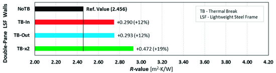
Figure 6.
Measured thermal resistance improvement due to aerogel thermal break strips.
When there are no thermal break strips (reference LSF wall) the measured thermal resistance is 2.456 m2·°C/W. Adding an inner or an outer TB strip provides similar -values (around 2.75 m2·°C/W), corresponding to a thermal resistance increase of about +0.29 m2·K/W (+12%). This -value increase is similar to the one achieved by adding 10 mm of continuous mineral wool (MW). The higher measured -value (2.928 m2·°C/W) is achieved when using two TB strips (inner and outer), allowing a thermal resistance improvement of +0.472 m2·K/W (+19%). Notice that the combined effect of these two TB strips (-value increase of +19%), is smaller than the summation of two single TB strips (+24%), i.e., inner (+12%) and outer (+12%).
3.2. Thermal Performance Improvement due to Aluminium Reflective Foils
The measured thermal resistance values and thermal performance enhancement due to aluminium reflective foils are displayed in Table 5, while Figure 7 exhibits a plot of these values.
Table 5.
Measured thermal resistance of double-pane LSF walls and thermal performance improvement due to aluminium reflective foils.
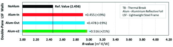
Figure 7.
Measured thermal resistance improvement due to aluminium reflective foils.
Notice that the reference -value (wall without aluminium reflective foil) remains the same, as in the previous subsection (2.456 m2·K/W). Adding an inner or an outer aluminium reflective foil provides similar -values (around 2.92 m2·K/W), corresponding to a thermal resistance increase of about +0.46 m2·K/W (+19%). This -value increase is similar to the one achieved by adding 16 mm of continuous mineral wool (MW). The higher measured -value (2.972 m2·K/W) is achieved when using two reflective foils (inner and outer), allowing a thermal resistance improvement of +0.516 m2·K/W (+21%).
Comparing these values with the previous ones for the TB strips (Table 4), it can be concluded that the thermal performance improvement due to aluminium reflective (AR) foils is more effective, allowing to achieve higher thermal resistances of the double-pane LSF wall. In fact, the -value improvement due to a single AR foil (inner or outer) is similar to the -value improvement provided by two aerogel TB strips (+19%).
Another interesting conclusion is that the use of two reflective foils is not so effective, since the thermal performance improvement, in comparison with only one aluminium reflective foil, is very reduced (about +2%).
3.3. Thermal Performance Improvement Due to Thermal Break Strips and Reflective Foils
Table 6 exhibits the measured -values for combined aerogel thermal break (TB) strips and aluminium reflective (AR) foils, as well as the corresponding thermal resistance increase. Figure 8 displays a graphical representation of these values, being grouped into three sets of R-values, depending on the number and location of TB strips (inner, outer, and both inner and outer). Notice that the reference -value remains the same (2.456 m2·°C/W) for all three sets of measurements.
Table 6.
Measured thermal resistance of double-pane LSF walls and thermal performance improvement due to aerogel thermal break strips and aluminium reflective foils.
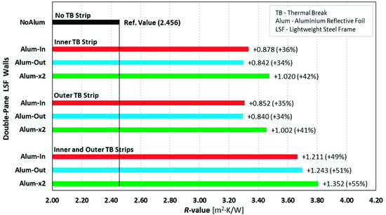
Figure 8.
Measured thermal resistance improvement due to aerogel thermal break strips and aluminium reflective foils.
The combined thermal resistance improvement, due to a single TB strip (inner or outer) and a single AR foil (inner or outer), is around 0.85 m2·K/W (+35%), being this value slightly higher than the summation of individual -values increase (+31%), obtained from Table 4 (+12%) and Table 5 (+19%).
Looking to the LSF walls with inner or outer TB strip, having two AR foils (inner and outer), the -value increase is around +1.01 m2·K/W (+41%). Again, this thermal resistance improvement (+41%) is higher than the summation of individual -values increase (+33%), obtained from Table 4 (+12%) and Table 5 (+21%), evidencing a bigger synergy outcome between the TB strips and the AR foils.
As expected, the higher measured thermal resistances are provided by the LSF walls with two TB strips. In this circumstance, when having an inner or an outer AR foil, the -value increase is about 1.23 m2·K/W (+50%). Once more, the summation of individual thermal performance improvement due to double TB strips (+19%) and due to one (inner or outer) AR foil (+19%) is smaller (only +38%) than their combined effect (about +50%).
The use of two AR foils, instead of a single one, only improved the thermal resistance by an additional 5%, i.e., +55% (+1.352 m2·°C/W) in relation to the reference LSF wall. The synergy effect remains, being even higher since this value (+55%) is considerably bigger than the summation (+40%) of individual improvement contribution from two TB strips (+19%, Table 4) and from two AR foils (+21%, Table 5). The -value increase measured for double TB strips combined with double AR foils (about +1.35 m2·°C/W) is similar to the one achieved by adding 47 mm of continuous mineral wool (MW).
4. Conclusions
In this paper, the thermal performance improvement Due to the use of aerogel thermal break (TB) strips and aluminium reflective (AR) foils in double-pane lightweight steel-framed walls were experimentally assessed. The lab measurements were performed using two mini climatic chambers (hot and cold) and the double-sided heat flow meter technic. Three sets of measurements were performed, considering the thermal performance improvement due to: (1) only aerogel TB strips; (2) only AR foils, and; (3) both TB strips and AR foils. Taking into account the three TB strips and AR foils locations, namely: (i) inner; (ii) outer; (iii) double (i.e., both inner and outer), as well as the reference LSF wall (without TB strips and AR foils), sixteen LSF walls’ configurations were measured.
As expected, the key findings address the research questions of this research work, being the main conclusions summarized as follows:
- Both aerogel TB strips and AR foils allowed to improve the thermal performance of a reference double-pane LSF wall, which has a conductive thermal resistance of 2.456 m2·K/W.
- Placing the aerogel TB strip on the inner or outer steel stud flange provides similar conductive -values, being the thermal resistance increment of about +0.29 m2·K/W (+12%).
- The use of inner or outer AR foils inside the air cavity also provides similar -values, but the effectiveness of this improvement measure is higher, exhibiting a thermal resistance increment of about +0.47 m2·K/W (+19%).
- In fact, using an AR foil inside the air cavity of double-pane LSF walls is much more effective than using aerogel TB strips along the steel flange, since only one AR foil (inner or outer) provides similar thermal resistance increase than two aerogel TB strips, i.e., around +0.47 m2·K/W (+19%).
- However, the use of two AR foils, instead of a single one, is not effective, since the relative thermal resistance increase is only about +0.04 m2·K/W (+2%).
- The combined effect of both TB strips and AR foils allowed to achieve a maximum -value increase of +1.35 m2·K/W (+55%).
- When combining these two thermal performance strategies, it was found a synergy effect between them, since the measured combined -value increase, when using both TB strips and AR foils, is bigger than the summation of individual -values increments.
- This synergy effect ranged from only +0.10 m2·K/W (+4%) for the thermal resistance increase due to a single TB strip and a single AR foil, up to +0.37 m2·K/W (+15%) when using two TB strips and two AR foils.
Notice that the higher effectiveness of the AR foils in comparison with the aerogel TB strips could be justified by the continuous air cavity (3 cm) and reflective foil, while the TB strips are restricted to the steel studs’ flanges. Moreover, the steel studs in the double-pane LSF wall are separated in two different frames (inner and outer wall panes), not crossing the wall and, this way, the related steel thermal bridge effect is very reduced.
The main practical applications and implications of the research findings are related the design of double-pane LSF walls, or refurbishment, whenever their thermal performance is not satisfactory. As mentioned above, the use of AR foil is more efficient than TB strips, even when they are made with a super insulation material (aerogel). Moreover, adding this AR foil to the inner or outer side of the air cavity originates a similar thermal performance increase. Furthermore, the use of two AR foils, instead of a singleone, is not effective.
Cost assessment is not within the scope of this research, being an interesting research idea for future work. However, the acquisition cost of aerogel TB strips is much higher than the cost of an AR foil. For example, the cost of an aerogel Spacetherm® CBS (Cold Bridge Strip) is around 3.80 €/m (50 mm wide and 10 mm thick), while the cost of a Space-Reflex® AR foil (4 mm thick) is around 2.35 €/m2. Assuming an LSF wall with a stud spacing equal to 400 mm and a high of 2.70 m, the unit consumption of a single TB strip is 3.30 m per wall square meter. Thus, the unit cost of this TB strip is around 12.54 €/m2 for this LSF wall. Therefore, the unit cost of the AR foil is around five times lower than the aerogel TB strip. Consequently, it can be concluded that besides the higher thermal efficiency of the AR foil, this performance improvement strategy is also much cheaper.
The main limitations of this research are: only one air cavity was assessed (30 mm thick); only one TB strip material was assessed (aerogel); only one reflective foil was assessed (aluminium); the measurements were performed in a double-pane LSF wall test-sample (without any wall ties, connectors or other bridging elements inside the air cavity) under controlled lab conditions in a near steady-state regimen (not having into account any transient effects due to daily temperature variations).
Energy consumption is not within the scope of this research, being a good research suggestion for future work. Nevertheless, the achieved thermal resistance increments (maximum absolute increased value of +1.35 m2·°C/W, corresponding to +55%) will allow for sure to reduce the heat losses across the building opaque envelope during the winter season and, consequently, to reduce energy consumption for space heating. This energy consumption reduction will be larger for colder climates.
Author Contributions
Conceptualization, P.S.; methodology, P.S.; validation, P.S. and T.R.; formal analysis, P.S.; investigation, P.S. and T.R.; writing—original draft preparation P.S.; writing—review and editing, P.S. and T.R.; visualization, P.S.; supervision, P.S.; project administration, P.S.; funding acquisition, P.S. All authors have read and agreed to the published version of the manuscript.
Funding
This research was funded by FEDER funds through the Competitivity Factors Operational Programme—COMPETE and by national funds through FCT—Foundation for Science and Technology within the scope of the project POCI-01-0145-FEDER-032061.

Institutional Review Board Statement
Not applicable.
Informed Consent Statement
Not applicable.
Acknowledgments
The authors also want to thank the support provided by the following companies: Pertecno, Gyptec Ibéria, Volcalis, Sotinco, Kronospan, Hulkseflux, Hilti and Metabo.
Conflicts of Interest
The authors declare no conflict of interest.
References
- European Union. Directive (EU) 2018/844 of the European Parliament and of the Council of 30 May 2018 Amending Directive 2010/31/EU on the energy performance of buildings and Directive 2012/27/EU on energy efficiency. Off. J. Eur. Union 2018, 2018, 75–91. [Google Scholar]
- Climate Action Network (CAN) Europe. How to Roll out the Energy Transition in Buildings. Factsheet 2021. Available online: https://caneurope.org/energy_transition_buildings_factsheet/ (accessed on 14 September 2021).
- European Union. Directive (EU) 2018/2001 of the European Parliament and of the Council on the promotion of the use of energy from renewable sources. Off. J. Eur. Union 2018, 328, 82–209, European Parliament. [Google Scholar]
- Santos, P.; Simões da Silva, L.; Ungureanu, V. Energy Efficiency of Light-Weight Steel-Framed Buildings, 1st ed.; European Convention for Constructional Steelwork (ECCS), Technical Committee 14—Sustainability & Eco-Efficiency of Steel Construction: Brussels, Belgium, 2012; ISBN 978-92-9147-105-8. [Google Scholar]
- Roque, E.; Santos, P. The Effectiveness of Thermal Insulation in Lightweight Steel-Framed Walls with Respect to Its Position. Buildings 2017, 7, 13. [Google Scholar] [CrossRef] [Green Version]
- Roque, E.; Santos, P.; Pereira, A.C. Thermal and sound insulation of lightweight steel-framed façade walls. Sci. Technol. Built Environ. 2019, 25, 156–176. [Google Scholar] [CrossRef]
- Berardi, U.; Sprengard, C. An overview of and introduction to current researches on super insulating materials for high-performance buildings. Energy Build. 2020, 214, 109890. [Google Scholar] [CrossRef]
- Lamy-Mendes, A.; Pontinha, A.D.R.; Alves, P.; Santos, P.; Durães, L. Progress in silica aerogel-containing materials for buildings’ thermal insulation. Constr. Build. Mater. 2021, 286, 122815. [Google Scholar] [CrossRef]
- Zach, J.; Peterková, J.; Dufek, Z.; Sekavčnik, T. Development of vacuum insulating panels (VIP) with non-traditional core materials. Energy Build. 2019, 199, 12–19. [Google Scholar] [CrossRef]
- Santos, P.V.F.; Martins, C.; Simoesdasilva, L. Thermal performance of lightweight steel-framed construction systems. Metall. Res. Technol. 2014, 111, 329–338. [Google Scholar] [CrossRef]
- Erhorn-Klutting, H.; Erhorn, H. ASIEPI P148—Impact of thermal bridges on the energy performance of buildings. In Buildings Platform; European Communities: Brussels, Belgium, 2009. [Google Scholar]
- Soares, N.; Santos, P.; Gervásio, H.; Costa, J.J.; Da Silva, L.S. Energy efficiency and thermal performance of lightweight steel-framed (LSF) construction: A review. Renew. Sustain. Energy Rev. 2017, 78, 194–209. [Google Scholar] [CrossRef]
- Martins, C.; Santos, P.; Simoesdasilva, L. Lightweight steel-framed thermal bridges mitigation strategies: A parametric study. J. Build. Phys. 2016, 39, 342–372. [Google Scholar] [CrossRef]
- Váradi, J.; Toth, E. Thermal Improvement of Lightweight Façades containing Slotted Steel Girders. In Twelfth International Conference on Civil, Structural and Environmental Engineering Computing; Funchal: Madeira, Portugal, 2009; p. 107. [Google Scholar]
- Lupan, L.M.; Manea, D.L.; Moga, L.M. Improving Thermal Performance of the Wall Panels Using Slotted Steel Stud Framing. Procedia Technol. 2016, 22, 351–357. [Google Scholar] [CrossRef] [Green Version]
- Santos, P.; Lemes, G.; Mateus, D. Thermal Transmittance of Internal Partition and External Facade LSF Walls: A Parametric Study. Energies 2019, 12, 2671. [Google Scholar] [CrossRef] [Green Version]
- Santos, P.; Mateus, D. Experimental assessment of thermal break strips performance in load-bearing and non-load-bearing LSF walls. J. Build. Eng. 2020, 32, 101693. [Google Scholar] [CrossRef]
- Kempton, L.; Kokogiannakis, G.; Green, A.; Cooper, P. Evaluation of thermal bridging mitigation techniques and impact of calculation methods for lightweight steel frame external wall systems. J. Build. Eng. 2021, 43, 102893. [Google Scholar] [CrossRef]
- Santos, P.; Gonçalves, M.; Martins, C.; Soares, N.; Costa, J.J. Thermal Transmittance of Lightweight Steel Framed Walls: Experimental Versus Numerical and Analytical Approaches. J. Build. Eng. 2019, 25, 100776. [Google Scholar] [CrossRef]
- Kapoor, D.R.; Peterman, K.D. Quantification and prediction of the thermal performance of cold-formed steel wall assemblies. Structures 2021, 30, 305–315. [Google Scholar] [CrossRef]
- Santos, P.; Poologanathan, K. The Importance of Stud Flanges Size and Shape on the Thermal Performance of Lightweight Steel Framed Walls. Sustainability 2021, 13, 3970. [Google Scholar] [CrossRef]
- Jelle, B.P.; Kalnæs, S.E.; Gao, T. Low-emissivity materials for building applications: A state-of-the-art review and future research perspectives. Energy Build. 2015, 96, 329–356. [Google Scholar] [CrossRef] [Green Version]
- Bruno, R.; Bevilacqua, P.; Ferraro, V.; Arcuri, N. Reflective thermal insulation in non-ventilated air-gaps: Experimental and theoretical evaluations on the global heat transfer coefficient. Energy Build. 2021, 236, 110769. [Google Scholar] [CrossRef]
- Santos, P.; Ribeiro, T. Thermal Performance of Double-Pane Lightweight Steel Framed Walls with and without a Reflective Foil. Buildings 2021, 11, 301. [Google Scholar] [CrossRef]
- Gyptec Ibérica. Technical Sheet: Standard Gypsum Plasterboard. 2021. Available online: https://www.gyptec.eu/documentos/Ficha_Tecnica_Gyptec_A.pdf (accessed on 19 April 2021). (In Portuguese).
- Volcalis_MineralWool. Technical Sheet: Alpha Panel Mineral Wool. 2021. Available online: https://www.volcalis.pt/categoria_file/fichatecnica_volcalis_alphapainel-777.pdf (accessed on 19 April 2021). (In Portuguese).
- Santos, C.; Matias, L. ITE50—Coeficientes de Transmissão Térmica de Elementos da Envolvente dos Edifícios (in Portuguese); LNEC—Laboratório Nacional de Engenharia Civil: Lisboa, Portugal, 2006. [Google Scholar]
- Rasooli, A.; Itard, L. In-situ characterization of walls’ thermal resistance: An extension to the ISO 9869 standard method. Energy Build. 2018, 179, 374–383. [Google Scholar] [CrossRef]
- ISO 9869-1. Thermal insulation—Building elements—In-situ measurement of thermal resistance and thermal transmittance. In Part 1: Heat Flow Meter Method; ISO—International Organization for Standardization: Geneva, Switzerland, 2014. [Google Scholar]
- ASTM-C1155–95(Reapproved-2013). Standard Practice for Determining Thermal Resistance of Building Envelope Components from the In-Situ Data; ASTM—American Society for Testing and Materials: Philadelphia, PA, USA, 2013. [Google Scholar]
- THERM; Software version 7.6.1; Lawrence Berkeley National Laboratory, United States Department of Energy: Berkeley, CA, USA, 2017. Available online: https://windows.lbl.gov/software/therm (accessed on 14 February 2019).
- EN ISO 6946. Building Components and Building Elements—Thermal Resistance and Thermal Transmittance—Calculation Methods; CEN—European Committee for Standardization: Brussels, Belgium, 2017. [Google Scholar]
- Santos, P.; Martins, C.; Simoesdasilva, L.; Bragança, L. Thermal performance of lightweight steel framed wall: The importance of flanking thermal losses. J. Build. Phys. 2013, 38, 81–98. [Google Scholar] [CrossRef] [Green Version]
Publisher’s Note: MDPI stays neutral with regard to jurisdictional claims in published maps and institutional affiliations. |
© 2021 by the authors. Licensee MDPI, Basel, Switzerland. This article is an open access article distributed under the terms and conditions of the Creative Commons Attribution (CC BY) license (https://creativecommons.org/licenses/by/4.0/).