Review

Review on Carbon Capture in ICE Driven Transport

by
Alexander García-Mariaca
1 and
Eva Llera-Sastresa
2,*
1
Escuela de Ingeniería y Arquitectura, University of Zaragoza, María de Luna s/n, 50018 Zaragoza, Spain
2
Department of Mechanical Engineering, CIRCE Research Institute, University of Zaragoza, María de Luna s/n, 50018 Zaragoza, Spain
*
Author to whom correspondence should be addressed.
Energies 2021, 14(21), 6865; https://doi.org/10.3390/en14216865
Submission received: 26 August 2021 / Revised: 7 October 2021 / Accepted: 19 October 2021 / Published: 20 October 2021
(This article belongs to the Section B3: Carbon Emission and Utilization)

Abstract

:
The transport sector powered by internal combustion engines (ICE) requires novel approaches to achieve near-zero CO2 emissions. In this direction, using CO2 capture and storage (CCS) systems onboard could be a good option. However, CO2 capture in mobile sources is currently challenging due to the operational and space requirements to install a CCS system onboard. This paper presents a systematic review of the CO2 capture in ICE driven transport to know the methods, techniques, and results of the different studies published so far. Subsequently, a case study of a CCS system working in an ICE is presented, where the energy and space needs are evaluated. The review reveals that the most suitable technique for CO2 capture is temperature swing adsorption (TSA). Moreover, the sorbents with better properties for this task are PPN-6-CH2-DETA and MOF-74-Mg. Finally, it shows that it is necessary to supply the energy demand of the CCS system and the option is to take advantage of the waste heat in the flue gas. The case study shows that it is possible to have a carbon capture rate above 68% without affecting engine performance. It was also found that the total volume required by the CCS system and fuel tank is 3.75 times smaller than buses operating with hydrogen fuel cells. According to the review and the case study, it is possible to run a CCS system in the maritime sector and road freight transport.

1. Introduction

The global necessity of maintaining economic growth produces an increase in energy consumption. Despite the efforts in decoupling both issues, this indicator continues to grow, being the industry, transport and residential sectors the major contributors with 79.1% of the total energy consumption in 2017 [1]. Electricity and heat production and the transport sector produced the highest CO2 emissions, at 41.4% and 24.5%, respectively [2].
To achieve the Paris agreement objective to limit the increase of the global temperature under 2 °C [3], the European Union (EU) has promoted renewable energies, energy efficiency, and fuel substitution policies [4]. These measures have allowed expanding technological innovations to reduce the CO2 in the energy, construction, industry, agriculture, and transport sectors.
Up to date, the technological innovations to reduce CO2 emissions in the transport sector revolve around four topics: the use of alternative fuels, such as biofuels, natural gas (NG), liquefied petroleum gas (LPG), and H2 [5,6]; the reduction of the fuel consumption is achieved through the enhanced engine thermal efficiency [7], by using eco-driving technologies [8,9]; the optimization of the engine energy-balance, transforming waste heat flows through Organic Rankine Cycles (ORC) or Thermo-Electric Generators (TEG) [10,11,12,13], the reduction of driving resistances [14], and the development of powertrains powered by electricity. The advantage of these vehicles (fuel cell vehicles and electric vehicles) is that they are CO2 zero-emission options, unlike the previously mentioned technologies.
These technologies have been insufficient to reduce the CO2 emissions from this sector, as is shown in Figure 1. However, the EU expects a substitution of internal combustion engine vehicles (ICEv) by electric vehicles (EVs) in urban transport from 2030, and it will be anticipated CO2 free city logistics in major urban centres by 2050 [15]. Nevertheless, EVs are far from replacing the engine combustion vehicles used in road freight transport due to low energy density and high weights in their batteries that result in low ranges [16]. On the other hand, according to the United States Environmental Protection Agency (US EPA), lithium-ion batteries not only increase environmental toxicity and cause global warming (due to the material extraction for its manufacture and final disposal of the batteries) but induce pulmonary and neurological diseases in people involved in the production chain [17].
Therefore, if the transport sector wants to be fully CO2 zero-emission, technological innovations used in other sectors must be considered to apply in road freight transport. The carbon capture and storage (CCS) technologies have been widely explored, but only some have the potential to capture the CO2 produced by ICEv used in road freight transport. CCS systems have been primarily used in power plants because they are the predominant source emitter of CO2 [19]. Until 2019, there were 19 large-scale CCS projects in operation, 4 installations are about to start, and 28 others are in various stages of development, with an estimated CO2 capture of 96 Mton per year [20], corresponding to 0.3% of the total CO2 emissions for 2017. In addition, 100 smaller-scale projects are currently ongoing [21].
The existing CCS systems have been adjusted to the nominal operation of power plants, almost always in a stationary mode. Therefore, in the selection of a CCS system for its implementation in an ICE driven vehicle (ship or truck), adaptation to the typical operating characteristics of the transport sector, such as variations of the mass flow and concentration of species in the FG due to acceleration, decelerations, and engine loads, must be considered. Where applicable, the use of CCS technologies in the transport sector should be coupled with a fuel that produces near-zero particle emissions, not to affect the operation of the selected capture method.
In addition, the selection of a CCS system to operate in the transport sector will depend on the end-use of the CO2 captured onboard. The possibility to produce synthetic methane to be subsequently used as fuel in the internal combustion engine (ICE) should be contemplated if a decarbonized and circular economy is pursued. The generation of synthetic methane combining electrolytic H2 from renewable electricity and CO2 captured from an existing source is a promising Power-to-Gas (PTG) technology due to its versatility [22,23,24,25,26,27] and the possibility of being integrated into the current NG supply and distribution system [28]. In addition, as several studies have shown [29,30], the vehicles that operate with this kind of fuel produce less noise and near-zero particulate matter. Integration of CO2 capture in synthetic methane fuelled engines would close the circle and move the ICE vehicle sector towards CO2 emission neutrality, which will counteract the problems noted above [31,32,33]. To sum up, the integration of CCS in the transport sector could be an excellent way to keep the existing ICE in the market under the upcoming near-zero CO2 emissions scenarios with zero presence of fossil fuels
This paper aims to ascertain which CCS technology already tested in power plants best adapts to the operational characteristics of an ICE used in maritime and road freight transport. First, a short review of the CCS technologies used in power plants is presented. Then, a review of patents and research studies on the CCS systems and techniques in the transport sector is conducted. Finally, a case study is developed to anticipate the energy and space requirements of the CCS system integrated into commercial ICEs for maritime and road freight transport. This paper tries to contribute to the state of the art of CCS with a critical and comprehensive analysis of the possibility of performing CO2 capture in mobile sources.

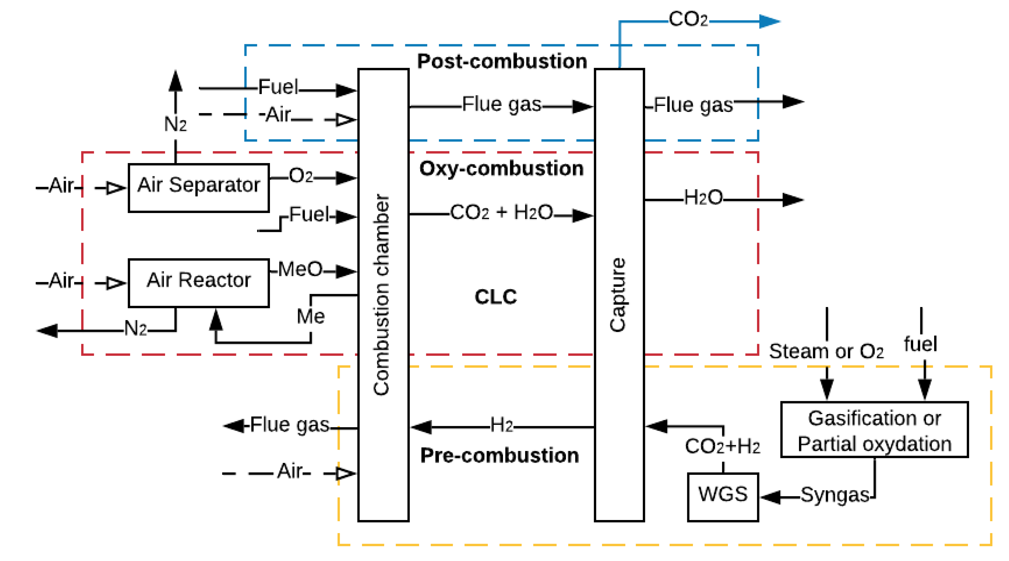
2. Carbon Capture and Storage

CCS refers to many technologies that capture CO2 at some stage of a combustion process or an industrial process that produces CO2 as waste [34,35,36]. In the first case, the CO2 capture can be carried out after the combustion process (post-combustion, oxy-combustion and chemical looping combustion) or before the combustion process (pre-combustion), as represented in Figure 2 [37]. The higher the partial pressure of CO2 in the gas, the better the efficiency of adsorption or absorption of CO2 [38,39].
In post-combustion, the capture occurs at a CO2 low partial pressure, while capturing through oxy-combustion, pre-combustion and chemical looping combustion (CLC), whose aim is to increase the CO2 concentration in the flue gas (FG), allows a higher partial pressure of CO2 in the gas. However, to increase the CO2 concentration, it is necessary to use additional equipment such as reactors or air separator units (ASU), which requires a large amount of power, thus decreasing the overall efficiency of the process [40].
In mobile sources as ICE driven ships and vehicles, the CO2 capture could be done by the three CCS methods shown in Figure 2. However, the CO2 capture in post-combustion is the predominant method by the nature of the powertrain used in this sector. According to Wang et al. [41], the main techniques that could be applied for CO2 capture in maritime transport are amine-absorption, temperature swing adsorption (TSA), cryogenisation and membrane processes. On the other hand, according to Sullivan and Sivak [42], the most promising CO2 capture technologies for the freight transport sector are amine-absorption and TSA. A short review of these techniques used in CCS is presented below.

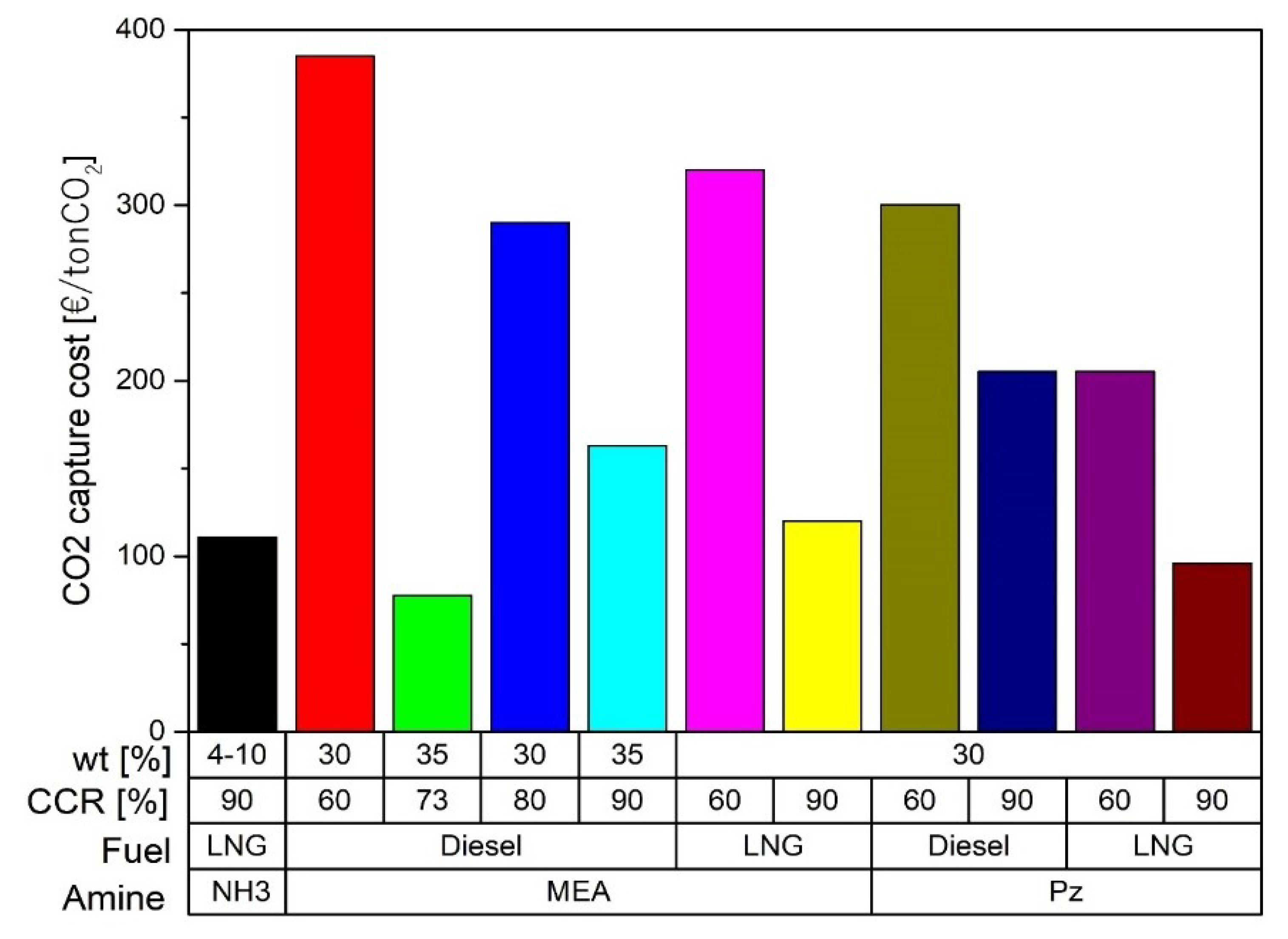
2.1. Amine-Absorption

CO2 capture by amine-absorption is the most mature and economical technology available today used in power plants [43]. According to Joel et al., Salazar et al. and MacDowell et al. [37,44,45], the installation consists of two interconnected columns. In the first column or absorber, the amine absorbs the CO2 from the FG in a counter-current reactor at temperatures between 40 and 60 °C and pressures around 1 bar. The clean FG leaves the absorber from the top, while the solution rich in CO2 is pumped from the bottom to the second column or stripper, where it is heated at temperatures between 80 and 120 °C with steam coming from the reboiler at 2 bars of pressure. This reaction breaks the chains between the CO2 and the amine, and the CO2 is released while the amine remains clean. Then, CO2 is compressed and stored, and the lean solution is repumped to the absorber in a cycling process, as shown in Figure 3 [46,47].
Absorption by amines causes a reduction of approximately 10 points in the overall efficiency of a power plant (there are still no experimental data of mobile sources) [50,51]. This reduction is caused by the vapour extracted in the turbine during the regeneration process and the energy consumed by pumping and compression (parasitic loads), as shown in Figure 3 [52,53]. The required properties of amines to be used in mobiles sources should be low absorption heat, to lessen energy requirements, and high CO2 loading capacity (q), to minimize amine mass in the CO2 capture. Table 1 shows some amines with suitable characteristics for the capture of CO2 in mobile sources.
Main problems with the amine-absorption include the degradation in operation at high temperatures and the need to make the FG free of acid emissions (SO2 and NOx) and particulate matter [66,67]. The amines are chemically unstable and highly corrosive in the presence of oxygen. Due to their high viscosity, aqueous amine solutions at a maximum concentration of 40 wt% [55] are used. One should not forget that amines are toxic to aquatic organisms and react with NOx producing carcinogenic compounds that affect human health [68,69].

2.2. Adsorption

The adsorption process is based on an intermolecular relationship among surface forces in solids and gases, largely dependent on the temperature, partial pressure, surface force and adsorbent pore sizes [46,70]. Several materials have an excellent potential for this process, i.e., Activated Carbon (AC), zeolites, alumina, silica adsorbent, carbon nanotubes, porous polymer networks (PPNs), metal-organic frameworks (MOFs) and others [71,72,73,74]. Furthermore, materials can be improved with the impregnation of amine sorbents [75]. The adsorption process cannot be used if there are high concentrations of CO2 in the FG because of the general low q of the sorbent, as shown in Table 2, but it is adequate for concentrations under 20% [76].
One of the techniques with the most significant potential to capture CO2 in ICEv is adsorption. Specifically, the TSA technique is the most suitable process due to the high thermal energy available in the FG in ICEv. TSA is a cyclic process that has four stages, as shown in Figure 4. Initially, the CO2 adsorption occurs at low temperatures (approximately 30 °C). Then, the sorbent bed is heated until the desorption temperature (around 150 °C). Thereafter, at this temperature, the sorbent releases the retained CO2. Finally, the bed is cooled to start another cycle of adsorption [82,83,84,85]. In general, the main limitations of this process are the reduction in the adsorption capacity when the FG stream is wet due to the hydrophilic character of the materials [86] and the low q (Table 2), which necessitates a large amount of material to achieve more quantities of captured CO2. However, the adsorption process can be adapted to several operation conditions because of its flexibility to configure the reactors [86,87,88].

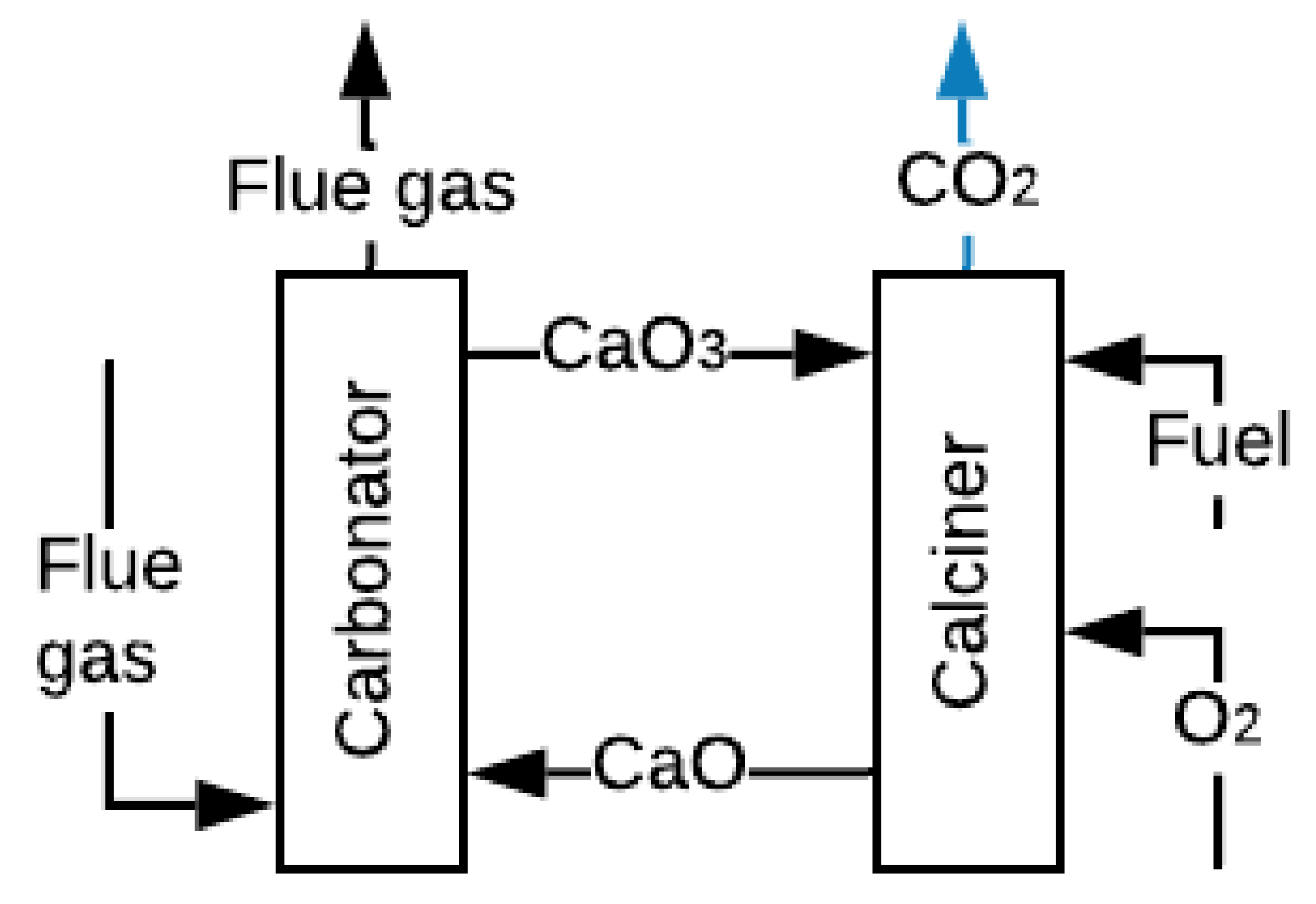
2.3. Carbonate Looping
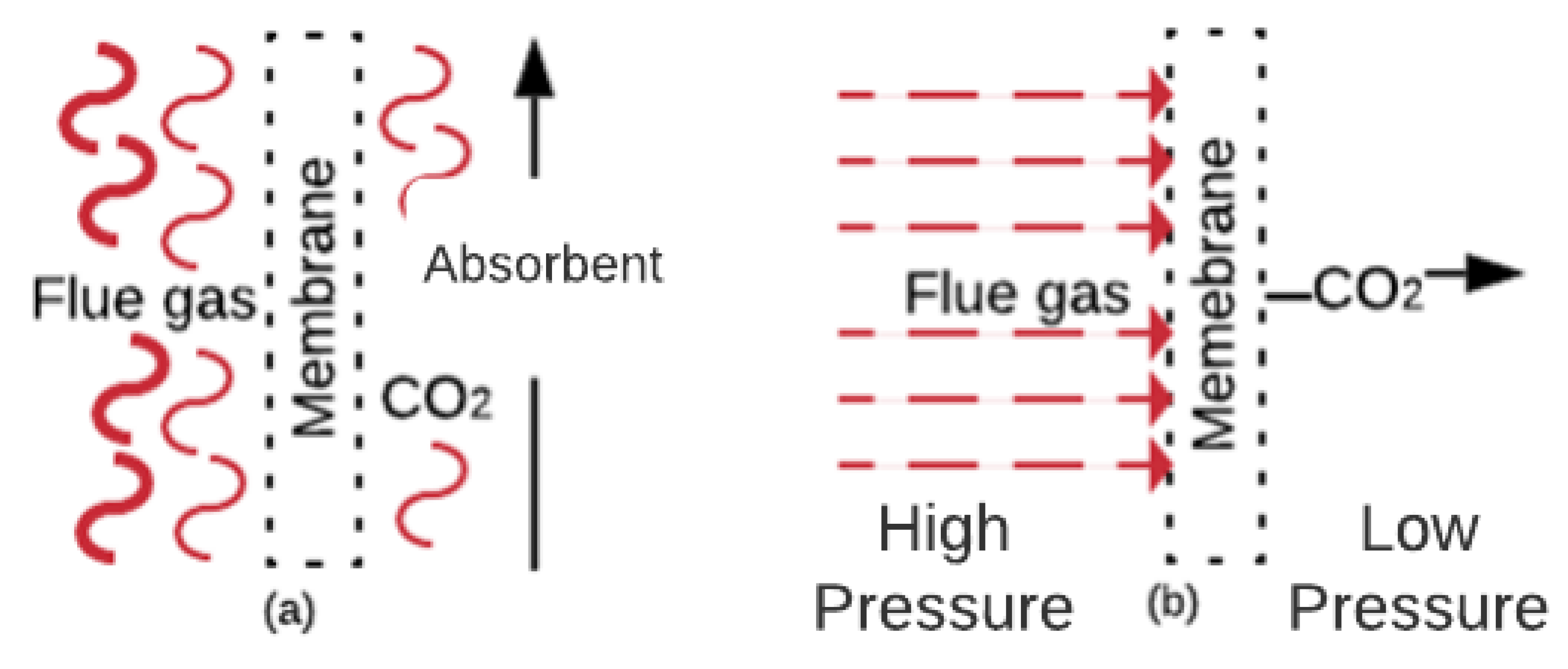
Carbonate Looping (CL), represented in Figure 5, has been widely investigated for CO2 capture, and CO2 captures up to 90% have been experimentally achieved [89]. The process involves reacting the FG with CaO at 650 °C and atmospheric pressure to obtain calcium carbonate CaCO3 and FG without CO2 [90]. The CaCO3 is carried to a second reactor where it is calcined at temperatures above 900 °C with pure oxygen, fuel and CO2, and regenerate sorbent (CaO) is produced [90,91]. This technology is very advantageous because it can also work for thermal energy storage. The calcination of solid CaCO3 with concentrated solar energy produces CO2 and CaO, which are stored for subsequent use [92]. However, this process requires high levels of energy consumption in the ASU to supply pure O2.

2.4. Membranes

CO2 capture with membranes is a concept developed in the nineteen-eighties and includes benefits such as being a compact, flexible and modular solution, as well as ease of maintenance and operation [93,94]. The involved mechanisms are solution/diffusion, adsorption/diffusion, molecular sieve, and ionic transport [46,95]. Figure 6a shows a gas absorption membrane contactor. In this membrane, the CO2 mass diffuses across the membrane and absorbs into the absorbent [96]. These membranes are usually composed of commercial polymers that absorb the CO2 from the FG. Figure 6b shows the gas separation membranes. In these membranes, the CO2 (in the FG at high pressure) diffuses through the membrane pores faster than other components [46]. Membranes that work under the separation principle are manufactured with ceramics, polymerics, and blends of both materials [46,97].
Several studies have tested the use of advanced materials, such as graphene, as fillers in a polymer matrix for separation [98] or have shown that a cascade configuration for compressors improved the energy consumption by achieving an increase in the efficiency of 3.8% with 70% CO2 separation in real-sized power plants [99]. Mathematical simulations of multi-stage membrane networks for coal-fired power plants [100] have shown that the optimal configuration is a three-stage configuration with a 98% rate of CO2 capture.
As this technology is in its first stage of implementation, the only applications have occurred at a lab-scale, so that the behaviour at a pilot-scale and full scale remains unknown [66]. Ongoing research is attempting to overcome the capture ratio, which cannot attain good values in only one membrane stage if the concentration of CO2 is high. For example, for a typical concentration of a coal power plant of approximately 15%, multiple stages of membranes are required, increasing the operational cost [101,102]. However, compared to the absorption process with MEA-scrubbing, membranes are still not competitive, as they need 2.3 times the cost of the operation, according to Jafari et al. [103]. Therefore, several authors have suggested that reducing the price of the membranes would have a significant impact due to the large area required to deal with typical gas flows [104].

2.5. Other Forms for CCS

There are other methods for CO2 capture that could be excellent alternatives to the previously described methods if the experimental stages are completed. Cryogenic CO2 capture has been able to accomplish a CO2 capture of approximately 99.99% [105]. Song et al. [106] describe seven methods (cryogenic packed bed, external cooling loop cryogenic carbon capture, anti-sublimation, cryogenic distillation, controlled freezing zone, cryoCell process and Stirling cooler system) for processing. The main problem with the cryogenic process is the high energy consumption required to keep the temperatures or to increase the pressures [106], and complications for the CO2 depositions over the heat transfer surface below its triple point (517 kPa and 56.6 °C) [107]. The bio-fixation of CO2 with microalgae for biodiesel production is a method that takes advantage of the high photosynthesis rate of microalgae. The process consists of passing the FG through a microalgae crop in the presence of solar radiation so that the microalgae capture the CO2. Moreover, this process is advantageous because it could be used in parallel with wastewater treatment and thus could result in a double benefit [108].

3. CCS in the Transport Sector

The applicability of the CO2 capture techniques in mobile sources, specifically in ships and ICE vehicles, faces several challenges, such as space limitations, natural conditions of operation (i.e., rapid acceleration and deceleration), energy requirements for additional devices, low concentrations of CO2 and low pressures in the FG [42]. In particular, the CO2 captured (as liquid) storage requires a tank three times larger than the fuel tank because the CO2 production in mass is three times higher for a mobile source that operates with diesel or gasoline [41]. Several studies of CCS systems mounted in ships and ICEv with the CO2 capture techniques have been developed previously. These approaches have been conducted from different perspectives, such as economic evaluations, operational conditions, simulations, and experimental oxy-fuel-combustion in ICE, pre-combustion, and even CO2 bio-fixation. The following sections are focused on the state of the art in CO2 capture from mobile sources as shown in patents and literature sources.

3.1. Maritime Sector

Shipping is the most efficient mode of transportation from the energy point of view [109], and their GHG emissions represent approximately 2% of global emissions [110]. In 2018, the International Maritime Organization (IMO) established a reduction of at least 50% CO2 by 2050 as an objective [111]. CCS is an excellent way to achieve this goal, in addition to other technologies to reduce CO2 emissions, such as hull air lubrication and wind-assist [112]. Furthermore, CO2 capture in ships is operationally advantageous, as engine loads and velocity are usually constant. These conditions produce constant concentration and FG mass flow (suitable for amine-absorption), and there is available space to install CCS systems. Moreover, it has also thought to perform research into storing the CO2 in the Liquified Natural Gas (LNG) tank when it is empty, taking advantage of the temperature and pressure conditions for the LNG storage. It would allow higher cargo space on the ship and, thus, more economic benefits of the CCS system. Table 3 summarises the recently published studies about CCS in the maritime sector reviewed in the following paragraphs.
The maritime sector has focused on investigations on simulations of CO2 capture employing amine-scrubbing, being the MEA, the Pz, and NH3 the amines more used [113,114,115,118,119]. These research works evaluated mainly the CO2 capture costs and the heat duty in the reboiler varying the CCR, the amine concentration in the solution, the pressure of CO2 compression, among other variables. As shown in Figure 7, the higher the amine concentration in the solution, the lower the heat duty in the reboiler. It can be explained because there is an increase in the CO2 loading in the solution, and therefore, there is a lower mass flow of solution for the same CCR, which produces a decrease in required heat duty in the reboiler.
Figure 7 also leads to predict that an increase of the CCR produces a rise in the heat duty in the reboiler. The absorption heat rules this behaviour because if more CO2 is captured, it will need more energy in the stripper to clean the solution. Consequently, the CO2 capture with MEA at 30 wt% presents a higher heat duty than Pz at 30 wt% due to the higher absorption heat of MEA than the Pz. The influence of the fuel is also represented in Figure 7, and it can be found that with Pz at 30 wt%, heating requirements are higher for an ICE fuelled with LNG than an ICE fuelled with diesel because there is less CO2 emission in an ICE fuelled with LNG. Finally, the gathered results show that the NH3 requires 3 times less solvent in the solution and 2.5 times less heat duty to achieve a CCR of 90%.
Regarding the CO2 capture costs summarized in Figure 8, there is a decreasing tendency as the CCR and the amine concentration in the solution increase. The most affordable CO2 capture cost is with Pz at 90% of CCR and with the engine fuelled with LNG, the value found is close to 100€ per ton of CO2. It is also observed that the CO2 capture cost with diesel is the costliest, mainly due to the higher price of this fuel relative to LNG. Fang et al. [116] also found that a ship operation with a CCR of 93% in the CCS system required an investment of 710,000 USD/MW.
Stec et al. [121] showed the influence of atmospheric conditions in the amine-absorption with MEA at 30%. The results show that CCR ranges from 31.4% in arctic conditions to 56.5% in tropical conditions. The higher CCR under tropical conditions can be explained as more waste heat from the FG is recovered, leading to a high CO2 capture. In addition, Lee et al. [122] studied the scenarios of CO2 reduction established by the IMO (45% 2030, 55% 2040 and 70% 2050) [113]. The simulation considered a blend MDEA at 22 wt% and Pz at 8 wt% as amines in the CCS system. The results show a reduction of CO2 in the maritime sector of 12.2, 34.8 and 68.3% in 2030, 2040 and 2050, respectively. These values of CO2 reduction are lower in 2030 and 2040, but in 2050, the CO2 reduction value is barely lower than that established by the IMO.
The second technique dealt with in the literature to capture CO2 in the maritime sector is the CL. Research shows that it is possible to obtain a CCR between 20 and 55.6% [117,120,123]. The operational costs of a ship with a CCS system would suffer an increase of 10.6% that can be reduced to 6.8% after selling the CaCO3 produced in the CO2 capture process [117]. However, the life cycle costs can be reduced by 40% compared to a ship without a CCS system [123]. The third technique used in the maritime sector is the adsorption with K2CO3 supported on an alumina base. Some experimental tests were carried out with a synthetic composition of FG of a marine diesel engine, obtaining a maximum CCR of 43% using a sorbent with a 3.6 wt% of K2CO3, making the carbonation and regeneration processes at 60 and 120 °C, respectively [125,126]. Finally, the last method of CO2 capture in the maritime sector found in the literature is proposed by Malmgren et al. [124]. It consists in capturing the CO2 onboard, transporting it to the port, processing it to convert into methanol, and then processing this into the ship through a precombustion process to obtain H2 (as a fuel of ICE). The life cycle assessment shows that it is possible to reduce climate change variables GWP20 and GWP100 by 98% and the particulate matter by 88% compared to a ship without the CCS system
The research works found in the literature show that the CO2 capture in the maritime sector is done chiefly using amine-scrubbing. This inclination in research could be due to the high industrial development that this type of CO2 capture technology has and the high availability of space on ships for its installation. In addition, a consensus in using waste heat from the FG to supply the energy required by the CCS system was found. Additionally, for the ships that operate with LNG, it is developed to take advantage of the available heat cooling to liquefy the CO2 captured. According to the review, it is clear that the CO2 reduction established by the IMO cannot be achieved without a CCS system in the ships. Finally, it is necessary to develop experimental tests to verify all the information provided by the authors, thus trying to close the gap and make the CCS systems in the maritime sector reality.

3.2. Internal Combustion Engines Vehicles (ICEv)

The CCS in vehicles is especially challenging due to the space available for installing devices and store the CO2 and the additional energy consumption of the system required for CO2 capture [42]. In this section, a review of patents and research summarized in Table 4 is conducted, focusing on the CO2 capture techniques and procedures and the extra components in the CCS system to operate.
The CCS methods used in ICEv, as found in the literature, are oxy-fuel combustion and post-combustion. According to several patents, oxy-fuel combustion could be conducted by membranes installed in the intake manifold, which separate the O2 from the air [153,154,155]. Perovskite membranes can perform this separation of O2 from the air, but these membranes require high temperatures (approximately 800 °C) to obtain an adequate oxygen flow for the combustion process [156]. This technique is not suitable for ICE because the admission system will need high-temperature materials and a robust cooling system to increase the O2 density, resulting in higher costs of the ICEv.
Another form to achieve oxi-fuel combustion in ICE’s is including an internal combustion Rankine cycle (ICRC). This cycle involves injecting fuel, O2, and water vapour (to limit the peak temperature in the combustion process) to obtain only CO2 and water in the FG [127,128,129,130,131,132,133,134,135]. The experimental tests developed on the engines working in oxi-fuel combustion evaluated the performance and emissions parameters varying the EGR, O2 concentration, the charge temperature in the intake manifold, compression ratio, among other variables. Obtained results show an increase of the indicated work of 7.8% with a 40% O2 in the intake manifold and thermal efficiency of 42% with an EGR of 5%. There is a decrease in the total hydrocarbons and CO emissions using wet EGR and an increase of O2 in the intake charge, and the NOx emissions present a reduction using wet EGR.
The second CCS method used in ICEv is the post-combustion capture.
Although membranes and microalgae bio-fixation techniques can also be found in the literature, absorption and adsorption are primary methods to capture CO2. Research works and patents with amine-scrubbing (absorption) are few. The patents describe how the CCS system would operate in an ICE [157,158,159]. These patents present new designs of scrubbers, configuration of the reactors, use of elements as TEG’s or ORC to take advantage of the waste heat of the FG to supply the system energetically. There is also research and private development with amine scrubbing. The study evaluated experimentally three primary amines at 30 wt% achieving a maximum CCR of 90% with regeneration energy corresponding to the 58% of the energy contained in the FG [136]. However, the regeneration energy of the amines was obtained by energy balance, and it did not consider the energy losses associated with the transformation of thermal energy to mechanical energy. Finally, the company Saudi Aramco has developed two CCS systems by absorption. The first is a solvent system assembled underneath a Toyota Camry’s chassis, achieving a CO2 capture of 25% [137]. The second prototype of the CCS system developed in 2019 uses a solvent based on amino acids, and it was installed at the top of a Class 8 Volvo heavy-duty truck. The company reported a CCR of 40% of this system was achieved [138].
The adsorption has been more investigated than amine-scrubbing to capture CO2 in ICEv. Several research works have evaluated different sorbents in SI-ICE and CI-ICE. The experimental tests were carried out with a sorbent bed installed in the exhaust gas pipe [139,140,141,142,143,144,145,146,147]. Figure 9 shows the results of CCR obtained by these investigations. As can be seen in this figure, the Zeolite X13 has the best performance with CCR values above 60% independent on the kind of ICE used. The sorbents impregnated with MEA also had an excellent performance regarding CCR, showing values close to the obtained by the zeolite X13. Both results are a consequence of the high CO2 loading of zeolite X13 and MEA, which improves CO2 capture when impregnated in sorbents.
It also was found a patent and a private development of CCS systems by adsorption in ICEv by the company Saudi Aramco. According to its website [137], the CCS system by adsorption (2011) consisted of integrating a solid sorbent into a Ford F-250 pickup truck, achieving a captured 10% of the CO2 emissions. The patent considers using the thermal energy from the FG to regenerate the sorbent and the thermal energy in the cooling engine system to compress the CO2 [160].
A complete study of the CCS system was performed by Sharma and Maréchal [148]. They made simulations of a TSA system with PPN-6-CH2 TETA as sorbent, a rotary wheel adsorbed for the process of regeneration of the sorbent and desorption of the CO2, an ORC, and heat pump for the energy requirements, and a CCR of 90%. The CO2 captured comes from a delivery truck that consumes 50 L of diesel and produces 117 kg of CO2 during 8 h of operation. The results show that it is possible to conduct the CO2 capture only with the energy supply by the FG. Although it is a comprehensive study, it does not consider the rpm and load engine variations, which could affect the performance of the CCS system proposed.
Devices that allow the use of solvents or sorbents for CO2 capture are also reported [149,161]. These devices achieve a CCR of 100% for periods of 70 min. However, it then drops to zero after 220 min of operation. Another CO2 capture technique proposed in post-combustion is the use of a high flux MFI-Alumina Hollow Fibers membrane. According to the simulations performed by Pera et al. [150], up to 75% CO2 can be captured with a 95% purity if a cascade of two hollow-fibre units is used.
Bio-fixation with microalgae or injection of H2 into the FG to produce methane through a reverse water-gas shift (RWGS) to use it again as a fuel in the engine have been also studied [151,152]. Despite being novel techniques, these techniques reported a low CCR and methane conversion. However, they are still far from being well developed to be considered in the short term.
This section has summarized the most important results obtained in the investigations related to the capture of CO2 in ICEv. As can be seen, patents on post-combustion by adsorption and absorption and oxi-fuel combustion with membranes were found. Regarding research works, experimental tests were carried out on post-combustion by adsorption, oxi-fuel combustion and bio-fixation. Simulations of post-combustion by adsorption and absorption and oxi-fuel combustion and membranes were also conducted.
Although there is a greater variety in CO2 capture techniques, only two works on post-combustion (one with adsorption and the other with TSA) consider the sorbent or amine regeneration and the CO2 storage. According to these works, the CO2 capture and storage could be done without affecting ICE performance. However, these works were performed under stationary conditions, and they did not consider variables such as the rpm and engine load in which a road freight transport vehicle would operate. The sorbents with the best results are sorbent impregnated with MEA, Zeolite X13 and PPN’s as sorbents. On the other hand, several research works developed interesting concepts of the CCS system on ICEv. However, these concepts are still impractical because the ICEv would need some modifications, such as additional tanks, reactors, fuel injection systems, and other devices.

4. Case Study

The transport sector of long distances will continue operating with the conventional combustion processes to obtain power. On this basis and considering the current developments in CCS technologies, there are significant opportunities to implant these technologies in ICE once the main challenges related to the operational characteristics have been overcome. After the review conducted in this paper, the TSA method is shown as the most suitable for CO2 capture in ICEv, but some research regarding practical and operational issues is lacking. This section estimates the energy and space requirements to install such a CCS system without affecting the engine’s performance.

4.1. Engine Selection

Two commercial engines used for road (bus) and maritime transport (ship) operating with CNG or LNG are selected. The engines are four-stroke, water cooling, turbo charged with aftercooler and multipoint fuel injection. Table 5 summarizes the main technical information of the engines.

4.2. Sorbent Selection

The sorbents selected for the case study should have low regeneration energy and high q and CO2/N2 selectivity. From the data in Table 2, the sorbents with the best values of the properties mentioned above are: PPN-6-CH2-DETA, MOF-74-Mg, and Zeolite-X13.

4.3. CCS System Description

As previously set, a CCS system with TSA for the CO2 capture operating in an ICE is considered. The CCS system will use the residual heat from the FG to increase the sorbent temperature and CO2 desorption. The remaining thermal energy in the FG is transformed into mechanical energy to produce power for the CO2 compression using an ORC. The ORC is one of the most studied and developed methods for that purpose [165]. In addition, this process produces the FG cooling, thus reducing the required power to finish cooling the sorbent, which is necessary for the adsorption process of CO2. Figure 10 shows the sketch of the CCS system proposed.
Initially, the CCS system will be considered to work with a CCR of 90%. Suppose the CCS system does not get to operate at a CCR of 90% without energy penalties. In that case, the highest CCR for each sorbent will be calculated, following the same procedure developed previously. Finally, with the results obtained before, the CO2 volume stored and the sorbent volume in the TSA process will be calculated. Calculations are described in the following sections.

4.4. Energy Balance

It is assumed that the engines will be fuelled with CH4 with a stoichiometric combustion process (air-fuel ratio of 17.13). The species in the FG will be only CO2, H2O and N2. The energy analysis for the engine M936G will take three temperatures corresponding at low, medium, and high engine loads as reported in research works (600, 700 and 800 K) for turbocharged SI-ICE [166,167]. The energy analysis for the maritime engine W9L46DF is done at 75% of engine load and 700 K FG temperature. Finally, the reference temperature taken for the calculations is 300 K. The mass fractions of the species in the FG and specific heats at the evaluated temperatures (obtained from the software EES) are listed in Table 6.
The available thermal energy is calculated at the turbine outlet of the SI-ICE (Equation (1)). As can be seen in this equation, it is necessary to obtain the FG mass flow, which is the sum of the air and fuel mass at the engine inlet. In the marine engine, this value is brought by the datasheet and, in the engine, it is the product of the fuel consumption per the average velocity (see Table 5). In addition, it is necessary to obtain the specific heat of the FG ( c p F G ) (Equation (2)). Finally, the difference temperature (ΔT) is the difference between the FG temperature in the turbine outlet and the reference temperature.
Q ˙ = m ˙ F G c p F G Δ T
c p F G = x C O 2 c p C O 2 + x N 2 c p N 2 + x H 2 O c p H 2 O
The regeneration heat for the sorbents ( Q ˙ r e g s o r b ) is the sum of the sensible heat ( Q ˙ s e n )   and the desorption heat ( Q ˙ d e s ) (Equations (3) and (4)). The ΔT in the Q ˙ s e n   takes into account a desorption temperature of 150 °C reported in the literature as a suitable temperature for the sorbents [73,168], and it is assumed an adsorption temperature of 30 °C. The desorption heat of the sorbents is taken from Table 2. Table 7 shows the results found.
Q ˙ r e g s o r b = Q ˙ d e s + Q ˙ s e n
Q ˙ r e g s o r b = 0.9 x C O 2 m ˙ F G Δ H d e s + c p C O 2 0.9 x C O 2 m ˙ F G Δ T + c p a d s 0.9 x C O 2 m ˙ F G q Δ T
Finally, the energy analysis is completed obtaining the power consumption to compress the CO2. To obtain this, firstly, the power output of the ORC ( W ˙ o u t ) (Equation (5)) is calculated. This equation takes the remaining heat in the FG ( Q ˙ r e m ) (Equation (6)), and an ORC cycle efficiency of 20%, that according to the literature, is the average value of ORC cycle efficiency working in ICE [169,170]. Table 8 and Table 9 show the results of the Q ˙ r e m and W ˙ o u t for each sorbent at the different evaluation temperatures.
W ˙ o u t = η O R C Q ˙ r e m
Q ˙ r e m = Q ˙ F G Q ˙ r e g
The power consumption of the CO2 compressor ( W ˙ c o m ) is obtained using the software ASPEN Plus. The simulation conditions are 1 bar, 150 °C (desorption temperature) at the inlet, 75 bar at the outlet. The compressor has an isentropic efficiency of 0.85 (Equation (7)).
W ˙ c o m = 0.9 x C O 2 m ˙ F G ( h 2 h 1 ) η s
The same calculation procedure is performed to estimate the maximum CCR that the CCS system could reach. However, it is not realistic to consider FG temperatures above or equal to 800 K during the engine performance at partial loads. In this case, a conservative temperature of 700 K for flue gases is considered. Table 9 shows the results obtained for each sorbent and engine.

4.5. Space Requirement

The space requirements for the CCS system are obtained in volume terms. The CO2 will be stored as a liquid at 75 bar and 25 °C, under these conditions, the CO2 density ( ρ C O 2 L ) is 762.6 kg/m3. The procedure starts obtaining the CO2 mass that will be stored. For this, it is assumed an operation of 8 h (Equation (8)). As shown in Figure 4, the TSA process is divided into four stages, and it is assumed that each stage will operate for 30 min. The sorbent mass and volume are calculated based on the previous assumptions (Equations (9) and (10)). Finally, the CO2 volume is obtained (Equation (11)), and the total volume of the CCS system is the sum of the CO2 and sorbent volumes (Equation (12)).
m C O 2 = 28800 C C R x C O 2 m ˙ F G
m s o r = m C O 2 4 q
V s o r = m s o r ρ s o r
V C O 2 = m C O 2 ρ C O 2 L
V T = V s o r + V C O 2

4.6. Results

Following the methodology described in the previous section, the quantities of remaining heat in the FG, the maximum CCR, ORR power, CO2 compression power, CO2 volume to store, and the CCS system’s total volume are estimated.

4.6.1. Energy Results

The results in Table 7 show that the available heat in the FG would be enough to regenerate the sorbent in the TSA process for all temperatures in both engines. This margin increases with the rise of the ΔT. Similarly, the remaining heat in the FG and the output power in the ORC have the same behaviour, as can be seen in Table 8 and Table 9.
The power consumptions of the CO2 compressor ( W ˙ c o m ) are 3.159 and 1029.9 kW for the M936G and the W9L46DF engines, respectively. Contrasting the results in Table 9 with the results of W ˙ c o m , it can be seen that the power output in the ORC working at an FG temperature of 800 K can cover the power consumption for the CO2 compressor with the CCS system using MOF-74-Mg as sorbent. In the other cases, the ORC cannot produce the power required to compress the CO2 under the FG temperatures and the established CCR. Moreover, the ICE in a vehicle will never continuously be operated at 100% of engine load. For that reason, we proceed to obtain the maximum CCR for each sorbent in both engines at 700 K of FG temperature that allows covering the CO2 compression without using additional energy from the ICE.
As shown in Figure 11, the sorbent MOF-74-Mg can achieve a CCR of 73% in both engines without affecting the engine’s performance. The sorbent PPN-6-CH2-DETA reaches 68% of CCR. Finally, the Zeolite X13 obtained a CCR of 64%. However, with this last result, the CO2 purity is 94.6%, while with the other sorbents, the CO2 purity is higher than 99.5%.

4.6.2. Space Results

As mentioned before, the selected sorbents are PPN-6-CH2-DETA and MOF-74-Mg due to high selectivity that allow a CO2 purity greater than 99.5%. In addition, the lowest CCR obtained of both sorbents will be used to compare the final volume resulting. Table 10 shows the results obtained.

5. Discussion

PPN-6-CH2-DETA and MOF-74-Mg as sorbents in TSA resulted into a CCR above 68% in both engines without affecting the engine performance. These results are mainly a consequence of the low regeneration heat of the sorbents. Therefore, there is still high thermal energy in the FG when it enters the ORC, producing more power output to cover the power required to compress the CO2 potentially.
Regarding sorbent selection, selectivity plays an important role in the CO2 purity obtained at the end of the process. For this reason, Zeolite X13 is discarded from the other sorbents studied in the following step because it achieves a CO2 purity of 94.6%, which is minor in 5 points than the other sorbents. The purification of CO2 captured when Zeolite X13 in TSA is used requires additional energy that the engine could not provide.
In a potential application, the FG must be dried completely as far as the selected sorbents lose CO2 uptake capacity. Then, it is expected that an additional cooling system will be required, which could imply parasitic loads not considered in this research. A comprehensive simulation of the integration of the CCS system and engine, which involves cooling and drying of the FG should be done. However, this is out of the scope of this paper.
The CCS system volume obtained with TSA for a CCR of 68% is approximately 0.3 m3 for the M936G engine (0.295 and 0.257 m3 with PPN-6-CH2-DETA and MOF-74-Mg, respectively). This engine usually operates in buses or trucks, allowing the CCS system to be mounted on the vehicle roof. It would not differ from other vehicles working with hydrogen fuel cells. For example, the Toyota Sora Bus uses hydrogen tanks that required 6 m3 [171]. If the same bus used two CCS systems with MOF-74-Mg to achieve a CCR of 100%, the CCS system only would require 0.6 m3, and added the volume of the fuel tank the global volume (CCS system and fuel tank) would be of 1,6 m3 approximately, which is 3.75 times smaller. Therefore, the values obtained in this research show that installing a CCS with TSA is practical in road freight transport.
In the marine engine, the mass of the sorbent is close to 40 tons, and the CCS volume is 90 m3. These are small values for ships because they usually have a large capacity of cargo and volume. The CCS system with TSA is presented as an excellent alternative to reduce CO2 emissions in the maritime sector.
Space requirements were obtained by considering the crystallographic density as it was impossible to obtain reliable and comparable bulk density data. Table 11 shows the values of the total volume assuming a bulk density as half of the crystallographic density. It is observed that the total volume has an increase of 50% with PPN-6-CH2-DETA and 43% with MOF-74-Mg in both engines. However, these values continue being lower than for the commercial vehicle previously mentioned and for a cargo ship.

6. Conclusions

A review of the CO2 capture in mobile sources and a case study to evaluate the potential of CCS systems to reduce the CO2 produced by ICE were made in this study. According to the detailed review presented here, the patents describe the devices or procedures used to carry out the CO2 capture. At the same time, research works show experimental tests or simulations of CO2 capture.
The choice of these two capture methods is based on the performance of the typical engines used in each sector and the available space for additional devices. As the ICE in a ship regularly operates at a constant regime (rpm and engine load), the continuous variation in the FG mass flow is not expected. This behaviour allows amine scrubbing to be more suitable for this operation. In addition, the cargo ships count with ample space available for the installation of devices required for a CCS system.
On the contrary, the ICEs mounted in road transport vehicles work with variable accelerations and available space to install the required equipment of a CCS system is scarce. For this case, adsorption is shown as the best option because it is a regenerative cyclical process that adapts to different mass flows of exhaust gases. In addition, according to the results obtained in the case study, it could require less space than other commercial vehicles using other CO2 reduction technologies.
The review shows that the research works have a higher level of development in the maritime sector than in the road transport sector. In addition, it was observed that the amine-absorption technology is the most used in the marine transport sector, and adsorption is preferable in the ICEv. Therefore, the TSA and amine-absorption are the most suitable pre-existing CCS technologies for CO2 capture for mobile sources due to their well-developed technology and low energy requirements. However, experimental reports on CO2 capture in ICEv lack information about the experimental conditions, such as engine load, RPM, and the energy of regeneration of the sorbent or solvent.
The results obtained in the case study show the first approximation of a CCS system operating with TSA and an ORC to take advantage of the thermal energy of the FG produced by ship engines. Regarding road freight transport, the results obtained in the case study show a big difference from the study done by Sharma and Maréchal (the most complete study so far). They report that it is possible to obtain a 90% CO2 capture without affecting the engine performance. The results found in the present case study show that it is possible to achieve this CCR but with sorbent MOF74-Mg at 800 K of FG temperature. However, taking a high FG temperature is not realistic because the engine operates at different engine loads and rpm. The best result obtained in the present case study is 73% of CCR with a temperature corresponding to the medium engine load. Nevertheless, the development of several studies contributes to close the gap to achieve the CO2 reduction targets established by the European Union for the ICE driven transport sector.
CNG and LNG are the fuels that should be used by the mobile source with operating a CCS system. First, these fuels produce less CO2 emissions than an ICE fuelled with diesel or gasoline, allowing a higher autonomy in terms of CO2 storage. Second, the CNG or LNG could be obtained from methanation with the CO2 and hydrogen produced from RES, and thus keep the door open to a sustainable and circular transport system centred on ICE.
A system that uses the TSA technique for CO2 capture was theoretically evaluated. According to the results, it is possible to obtain a CCR of 73% and a small volume to operate a CCS system without any supply of additional energy with TSA and MOF-74-Mg as sorbent at a medium engine load condition.
This paper highlights that capture in mobile sources can be developed with available technology, opening opportunities for CO2 capture in road freight and maritime transport. However, research must continue until a suitable commercial technology is demonstrated to reduce the CO2 in the atmosphere.
Future research works must give detailed information on the behaviour of the CCS system at partial engines loads and at several rpm conditions, the reduction in engine performance due to backpressure caused by the installation of additional devices in the exhaust pipe, as well as the increase in fuel consumption due to the additional weight of the CCS systems installed in the vehicles. According to US EPA, each 45 kg of extra weight in vehicles originates a 1% increase in the fuel consumption, although this affects smaller vehicles more (less than 2720 kg of weight) than larger ones such as buses or trucks [172,173]. In addition, it is necessary to do detailed research on the degradation of sorbent due to the impact of minor species present in the FG as NOx and unburned hydrocarbons. Finally, research on energy demands and economic and environmental life cycle assessments is required to conclude the viability of installing a CCS system in mobile sources.

Author Contributions

Conceptualization, A.G.-M. and E.L.-S.; methodology, A.G.-M. and E.L.-S.; software, A.G.-M.; validation, A.G.-M. and E.L.-S.; formal analysis, A.G.-M. and E.L.-S.; investigation, A.G.-M. and E.L.-S.; resources, A.G.-M.; data curation, A.G.-M.; writing—original draft preparation, A.G.-M. and E.L.-S.; writing—review and editing, A.G.-M. and E.L.-S.; supervision, E.L.-S. All authors have read and agreed to the published version of the manuscript.

Funding

This research received no external funding.

Institutional Review Board Statement

Not applicable.

Informed Consent Statement

Not applicable.

Data Availability Statement

The data will be made available at reasonable request from the corresponding author.

Acknowledgments

A part of this study was developed thanks to the support of the Scholarships for Iberoamerican Doctoral Students granted by the Universidad de Zaragoza—Santander Universidades, the CIRCE Research Institute, and the aid by the Research Groups of the Aragon Government (T46_17R).

Conflicts of Interest

The authors declare no conflict of interest.

Abbreviations

The following abbreviations are used in this manuscript
Q ˙ d e s Desorption Heat
Q ˙ r e g s o r b Sorbent Regeneration Heat
Q ˙ r e m Remaining Heat in the FG
Q ˙ s e n   Sensible Heat
W ˙ c o m CO2 Compressor Power
W ˙ o u t ORC Power Output
Δ H a b s Absorption Heat
Δ H a d s Adsorption Heat
c p Specific Heat
Δ T Difference Temperature
ACActivate Carbon
ASUAir Separator Units
CCSCO2 Capture and Storage
CLCarbonate Looping
CLCChemical Looping Combustion
DEADiethanolamine
EUEuropean Union
EVsElectric Vehicles
FGFlue gas
ICEInternal Combustion Engines
ICEvInternal Combustion Engine Vehicles
ICRCInternal Combustion Rankine Cycle
IMOInternational Maritime Organization
LNG Liquified Natural Gas
LPGLiquefied Petroleum Gas
MDEAMethyl Diethanolamine
MEAEthanolamine
MOFsMetal-Organic Frameworks
NGNatural Gas
ORCOrganic Rankine Cycle
PPNsPorous Polymer Networks
PTGPower to Gas
PzPiperazine
RWGSReverse Water-Gas Shift
TEGThermo-Electric Generators
TSATemperature Swing Adsorption
US-EPAUnited States Environmental Protection Agency
q CO2 Loading Capacity
x Mass Fraction
ρ Density

References

  1. IEA Total Final Consumption (TFC) by Sector, World 1990–2017. Available online: https://www.iea.org/data-and-statistics?country=WORLD&fuel=Energy%20consumption&indicator=Total%20final%20consumption%20(TFC)%20by%20sector (accessed on 27 November 2019).
  2. Bellocchi, S.; De Falco, M.; Gambini, M.; Manno, M.; Stilo, T.; Vellini, M. Opportunities for power-to-Gas and Power-to-liquid in CO2-reduced energy scenarios: The Italian case. Energy 2019, 175, 847–861. [Google Scholar] [CrossRef]
  3. Hof, A.F.; den Elzen, M.G.J.; Admiraal, A.; Roelfsema, M.; Gernaat, D.E.H.J.; van Vuuren, D.P. Global and regional abatement costs of Nationally Determined Contributions (NDCs) and of enhanced action to levels well below 2 °C and 1.5 °C. Environ. Sci. Policy 2017, 71, 30–40. [Google Scholar] [CrossRef]
  4. European Commission. A Clean Planet for all A European Long-Term Strategic Vision for a Prosperous, Modern, Competitive and Climate Neutral Economy; European Commission: Luxembourg, 2018; Volume 773, p. 114. [Google Scholar]
  5. Tamborra, M. European Commission, DG Research. 2006. Available online: https://www.iccr.org/ (accessed on 27 November 2019).
  6. Akram, M.; Ali, U.; Best, T.; Blakey, S.; Finney, K.N.; Pourkashanian, M. Performance evaluation of PACT Pilot-plant for CO2 capture from gas turbines with Exhaust Gas Recycle. Int. J. Greenh. Gas Control. 2016, 47, 137–150. [Google Scholar] [CrossRef]
  7. Leach, F.; Kalghatgi, G.; Stone, R.; Miles, P. The scope for improving the efficiency and environmental impact of internal combustion engines. Transp. Eng. 2020, 1, 100005. [Google Scholar] [CrossRef]
  8. Huang, Y.; Ng, E.C.Y.; Zhou, J.L.; Surawski, N.C.; Chan, E.F.C.; Hong, G. Eco-driving technology for sustainable road transport: A review. Renew. Sustain. Energy Rev. 2018, 93, 596–609. [Google Scholar] [CrossRef]
  9. Fafoutellis, P.; Mantouka, E.G.; Vlahogianni, E.I. Eco-driving and its impacts on fuel efficiency: An overview of technologies and data-driven methods. Sustainability 2021, 13, 226. [Google Scholar] [CrossRef]
  10. Agudelo, A.F.; García-Contreras, R.; Agudelo, J.R.; Armas, O. Potential for exhaust gas energy recovery in a diesel passenger car under European driving cycle. Appl. Energy 2016, 174, 201–212. [Google Scholar] [CrossRef]
  11. Merkisz, J.; Fuc, P.; Lijewski, P.; Ziolkowski, A.; Wojciechowski, K.T. The Analysis of Exhaust Gas Thermal Energy Recovery Through a TEG Generator in City Traffic Conditions Reproduced on a Dynamic Engine Test Bed. J. Electron. Mater. 2015, 44, 1704–1715. [Google Scholar] [CrossRef] [Green Version]
  12. Arsie, I.; Cricchio, A.; Pianese, C.; Ricciardi, V.; De Cesare, M. Modeling analysis of waste heat recovery via thermo-electric generator and electric turbo-compound for CO2 reduction in automotive SI engines. Energy Procedia 2015, 82, 81–88. [Google Scholar] [CrossRef] [Green Version]
  13. Sprouse, C.; Depcik, C. Review of organic Rankine cycles for internal combustion engine exhaust waste heat recovery. Appl. Therm. Eng. 2013, 51, 711–722. [Google Scholar] [CrossRef]
  14. Kühlwein, J. Driving Resistances of Light-Duty Vehicles in Europe: Present Situation, Trends and Scenarios for 2025. Communications 2016, 49, 847129-102. [Google Scholar]
  15. European Commission. Roadmap to a Single European Transport Area—Towards a Competitive and Resource Efficient Transport System; European Commission: Brussels, Belgium, 2011. [Google Scholar]
  16. EV-Volumes—The Electric Vehicle World Sales Database. Available online: https://www.ev-volumes.com/news/global-bev-phev-sales-for-2019/%0Ahttp://www.ev-volumes.com/country/total-euefta-plug-in-vehicle-volumes-2/ (accessed on 29 November 2019).
  17. Amarakoon, S.; Smith, J.; Segal, B. Lithium-ion Batteries and Nanotechnology for Electric Vehicles; EPA 744-R-12-001; US Environmental Protection Agency: Wasinghton, DC, USA, 2012.
  18. European Environmental Agency. Greenhouse Gas Emissions from Transport in Europe—European Environment Agency; European Environmental Agency: København, Denmark, 2018; pp. 1–7. [Google Scholar]
  19. Wang, D.; Li, S.; Liu, F.; Gao, L.; Sui, J. Post combustion CO2 capture in power plant using low temperature steam upgraded by double absorption heat transformer. Appl. Energy 2018, 227, 603–612. [Google Scholar] [CrossRef]
  20. New Wave of CCS Activity: Ten Large-Scale Projects Announced—Global CCS Institute. Available online: https://www.globalccsinstitute.com/news-media/press-room/media-releases/new-wave-of-ccs-activity-ten-large-scale-projects-announced/ (accessed on 17 February 2020).
  21. International Energy Agency. 20 Years Carbon Capture Storage; OECD: Paris, France, 2016. [Google Scholar] [CrossRef]
  22. Eveloy, V.; Gebreegziabher, T. A Review of Projected Power-to-Gas Deployment Scenarios. Energies 2018, 11, 1824. [Google Scholar] [CrossRef] [Green Version]
  23. Llera, E.; Romeo, L.M.; Bailera, M.; Osorio, J.L. Exploring the integration of the power to gas technologies and the sustainable transport. Int. J. Energy Prod. Manag. 2018, 3, 1–9. [Google Scholar] [CrossRef] [Green Version]
  24. Streibel, M.; Nakaten, N.; Kempka, T.; Kühn, M. Analysis of an integrated carbon cycle for storage of renewables. Energy Procedia 2013, 40, 202–211. [Google Scholar] [CrossRef] [Green Version]
  25. Kühn, M.; Nakaten, N.; Streibel, M.; Kempka, T. CO2 geological storage and utilization for a carbon neutral “power-to-gas-to-power” cycle to even out fluctuations of renewable energy provision. Energy Procedia 2014, 63, 8044–8049. [Google Scholar] [CrossRef] [Green Version]
  26. Götz, M.; Lefebvre, J.; Mörs, F.; McDaniel Koch, A.; Graf, F.; Bajohr, S.; Reimert, R.; Kolb, T. Renewable Power-to-Gas: A technological and economic review. Renew. Energy 2016, 85, 1371–1390. [Google Scholar] [CrossRef] [Green Version]
  27. Rönsch, S.; Schneider, J.; Matthischke, S.; Schlüter, M.; Götz, M.; Lefebvre, J.; Prabhakaran, P.; Bajohr, S. Review on methanation—From fundamentals to current projects. Fuel 2016, 166, 276–296. [Google Scholar] [CrossRef]
  28. Hagos, D.A.; Ahlgren, E. A State-of-the Art Review on the Development of CNG/LNG Infrastructure and Natural Gas Vehicles (NGVs); Chalmers University of Technology: Göteborg, Sweden, 2017. [Google Scholar]
  29. Osorio-Tejada, J.L.; Llera-Sastresa, E.; Scarpellini, S. A multi-criteria sustainability assessment for biodiesel and liquefied natural gas as alternative fuels in transport systems. J. Nat. Gas Sci. Eng. 2017, 42, 169–186. [Google Scholar] [CrossRef] [Green Version]
  30. Osorio-Tejada, J.L.; Llera-Sastresa, E.; Scarpellini, S. Liquefied natural gas: Could it be a reliable option for road freight transport in the EU? Renew. Sustain. Energy Rev. 2017, 71, 785–795. [Google Scholar] [CrossRef] [Green Version]
  31. Kalghatgi, G.; Levinsky, H.; Colket, M. Future transportation fuels. Prog. Energy Combust. Sci. 2018, 69, 103–105. [Google Scholar] [CrossRef]
  32. Horvath, S.; Fasihi, M.; Breyer, C. Techno-economic analysis of a decarbonized shipping sector: Technology suggestions for a fleet in 2030 and 2040. Energy Convers. Manag. 2018, 164, 230–241. [Google Scholar] [CrossRef]
  33. Mikulčić, H.; Ridjan Skov, I.; Dominković, D.F.; Wan Alwi, S.R.; Manan, Z.A.; Tan, R.; Duić, N.; Hidayah Mohamad, S.N.; Wang, X. Flexible Carbon Capture and Utilization technologies in future energy systems and the utilization pathways of captured CO2. Renew. Sustain. Energy Rev. 2019, 114, 109338. [Google Scholar] [CrossRef]
  34. Boot-Handford, M.E.; Abanades, J.C.; Anthony, E.J.; Blunt, M.J.; Brandani, S.; Mac Dowell, N.; Fernández, J.R.; Ferrari, M.C.; Gross, R.; Hallett, J.P.; et al. Carbon capture and storage update. Energy Environ. Sci. 2014, 7, 130–189. [Google Scholar] [CrossRef]
  35. Belaissaoui, B.; Le Moullec, Y.; Willson, D.; Favre, E. Hybrid membrane cryogenic process for post-combustion CO2 capture. J. Memb. Sci. 2012, 415–416, 424–434. [Google Scholar] [CrossRef]
  36. Voldsund, M.; Gardarsdottir, S.O.; De Lena, E.; Pérez-Calvo, J.F.; Jamali, A.; Berstad, D.; Fu, C.; Romano, M.; Roussanaly, S.; Anantharaman, R.; et al. Comparison of technologies for CO2 capture from cement production—Part 1: Technical evaluation. Energies 2019, 12, 559. [Google Scholar] [CrossRef] [Green Version]
  37. MacDowell, N.; Florin, N.; Buchard, A.; Hallett, J.; Galindo, A.; Jackson, G.; Adjiman, C.S.; Williams, C.K.; Shah, N.; Fennell, P. An overview of CO2 capture technologies. Energy Environ. Sci. 2010, 3, 1645–1669. [Google Scholar] [CrossRef] [Green Version]
  38. Sipöcz, N.; Hernandez-Nogales, A.; Gonzalez-Salazar, M.A.; Shisler, R.; Lissianski, V. Low temperature CO2 capture for near-term applications. Energy Procedia 2013, 37, 1228–1238. [Google Scholar] [CrossRef] [Green Version]
  39. Hu, Y.; Yan, J. Characterization of flue gas in oxy-coal combustion processes for CO2 capture. Appl. Energy 2012, 90, 113–121. [Google Scholar] [CrossRef]
  40. Olajire, A.A. CO2 capture and separation technologies for end-of-pipe applications—A review. Energy 2010, 35, 2610–2628. [Google Scholar] [CrossRef]
  41. Wang, H.; Zhou, P.; Wang, Z. Reviews on current carbon emission reduction technologies and projects and their feasibilities on ships. J. Mar. Sci. Appl. 2017, 16, 129–136. [Google Scholar] [CrossRef]
  42. Sullivan, J.M.; Sivak, M. Carbon Capture in Vehicles: A Review of General Support, Available Mechanisms, and Consumer Acceptance Issues; University of Michigan, Ann Arbor, Transportation Research Institute: Ann Arbor, MI, USA, 2012. [Google Scholar]
  43. Echevarria Huaman, R.N. A Review on: CO2 Capture Technology on Fossil Fuel Power Plant. J. Fundam. Renew. Energy Appl. 2015, 5. [Google Scholar] [CrossRef] [Green Version]
  44. Joel, A.S.; Wang, M.; Ramshaw, C. Modelling and simulation of intensified absorber for post-combustion CO2 capture using different mass transfer correlations. Appl. Therm. Eng. 2015, 74, 47–53. [Google Scholar] [CrossRef]
  45. Salazar, J.; Diwekar, U.; Joback, K.; Berger, A.H.; Bhown, A.S. Solvent selection for post-combustion CO2 capture. Energy Procedia 2013, 37, 257–264. [Google Scholar] [CrossRef] [Green Version]
  46. Mondal, M.K.; Balsora, H.K.; Varshney, P. Progress and trends in CO2 capture/separation technologies: A review. Energy 2012, 46, 431–441. [Google Scholar] [CrossRef]
  47. Jonshagen, K.; Sipöcz, N.; Genrup, M. A Novel Approach of Retrofitting a Combined Cycle with Post Combustion CO2 Capture. J. Eng. Gas Turbines Power 2011, 133, 1–7. [Google Scholar] [CrossRef]
  48. Xue, B.; Yu, Y.; Chen, J.; Luo, X.; Wang, M. A comparative study of MEA and DEA for post-combustion CO2 capture with different process configurations. Int. J. Coal Sci. Technol. 2017, 4, 15–24. [Google Scholar] [CrossRef] [Green Version]
  49. Zhai, R.; Liu, H.; Wu, H.; Yu, H.; Yang, Y. Analysis of integration of MEA-based CO2 capture and solar energy system for coal-based power plants based on thermo-economic structural theory. Energies 2018, 11, 1284. [Google Scholar] [CrossRef] [Green Version]
  50. Goto, K.; Yogo, K.; Higashii, T. A review of efficiency penalty in a coal-fired power plant with post-combustion CO2 capture. Appl. Energy 2013, 111, 710–720. [Google Scholar] [CrossRef]
  51. Eldardiry, H.; Habib, E. Carbon capture and sequestration in power generation: Review of impacts and opportunities for water sustainability. Energy. Sustain. Soc. 2018, 8, 6. [Google Scholar] [CrossRef] [Green Version]
  52. Hanak, D.P.; Biliyok, C.; Manovic, V. Efficiency improvements for the coal-fired power plant retrofit with CO2 capture plant using chilled ammonia process. Appl. Energy 2015, 151, 258–272. [Google Scholar] [CrossRef]
  53. Borhani, T.N.; Wang, M. Role of solvents in CO2 capture processes: The review of selection and design methods. Renew. Sustain. Energy Rev. 2019, 114, 109299. [Google Scholar] [CrossRef]
  54. Sada, E.; Kumazawa, H.; Butt, M.A. Gas absorption with consecutive chemical reaction: Absorption of carbon dioxide into aqueous amine solutions. Can. J. Chem. Eng. 1976, 54, 421–424. [Google Scholar] [CrossRef]
  55. Kim, Y.E.; Lim, J.A.; Jeong, S.K.; Yoon, Y.I.; Bae, S.T.; Nam, S.C. Comparison of carbon dioxide absorption in aqueous MEA, DEA, TEA, and AMP solutions. Bull. Korean Chem. Soc. 2013, 34, 783–787. [Google Scholar] [CrossRef] [Green Version]
  56. El Hadri, N.; Quang, D.V.; Goetheer, E.L.V.; Abu Zahra, M.R.M. Aqueous amine solution characterization for post-combustion CO2 capture process. Appl. Energy 2017, 185, 1433–1449. [Google Scholar] [CrossRef]
  57. Derks, P.W.J.; Versteeg, G.F. Kinetics of absorption of carbon dioxide in aqueous ammonia solutions. Energy Procedia 2009, 1, 1139–1146. [Google Scholar] [CrossRef] [Green Version]
  58. Qin, F.; Wang, S.; Kim, I.; Svendsen, H.F.; Chen, C. Heat of absorption of CO2 in aqueous ammonia and ammonium carbonate/carbamate solutions. Int. J. Greenh. Gas Control. 2011, 5, 405–412. [Google Scholar] [CrossRef]
  59. Qi, G.; Wang, S.; Yu, H.; Wardhaugh, L.; Feron, P.; Chen, C. Development of a rate-based model for CO2 absorption using aqueous NH3 in a packed column. Int. J. Greenh. Gas Control. 2013, 17, 450–461. [Google Scholar] [CrossRef]
  60. Yang, N.; Yu, H.; Li, L.; Xu, D.; Han, W.; Feron, P. Aqueous Ammonia (NH3) Based Post Combustion CO2 Capture: A Review. Oil Gas Sci. Technol. 2014, 69, 931–945. [Google Scholar] [CrossRef] [Green Version]
  61. Yu, H.; Morgan, S.; Allport, A.; Cottrell, A.; Do, T.; Wardhaugh, J.M.G.L.; Feron, P. Results from trialling aqueous NH3 based post combustion capture in a pilot plant at Munmorah power station: Desorption. Chem. Eng. Res. Des. 2012, 89, 753–758. [Google Scholar] [CrossRef]
  62. Bishnoi, S.; Rochelle, G.T. Absorption of carbon dioxide into aqueous piperazine: Reaction kinetics, mass transfer and solubility. Chem. Eng. Sci. 2000, 55, 5531–5543. [Google Scholar] [CrossRef]
  63. Chen, X.; Rochelle, G.T. Aqueous piperazine derivatives for CO2 capture: Accurate screening by a wetted wall column. Chem. Eng. Res. Des. 2011, 89, 1693–1710. [Google Scholar] [CrossRef]
  64. Singto, S.; Supap, T.; Idem, R.; Tontiwachwuthikul, P.; Tantayanon, S. The Effect of Chemical Structure of Newly Synthesized Tertiary Amines Used for the Post Combustion Capture Process on Carbon dioxide (CO2): Kinetics of CO2 Absorption Using the Stopped-Flow Apparatus and Regeneration, and Heat Input of CO2 Regeneration. Energy Procedia 2017, 114, 852–859. [Google Scholar] [CrossRef]
  65. Ali, B.S.; Aroua, M.K. Effect of piperazine on CO2 loading in aqueous solutions of MDEA at low pressure. Int. J. Thermophys. 2004, 25, 1863–1870. [Google Scholar] [CrossRef]
  66. Wang, Y.; Zhao, L.; Otto, A.; Robinius, M.; Stolten, D. A Review of Post-combustion CO2 Capture Technologies from Coal-fired Power Plants. Energy Procedia 2017, 114, 650–665. [Google Scholar] [CrossRef]
  67. Conway, W.; Yang, Q.; James, S.; Wei, C.C.; Bown, M.; Feron, P.; Puxty, G. Designer amines for post combustion CO2 capture processes. Energy Procedia 2014, 63, 1827–1834. [Google Scholar] [CrossRef] [Green Version]
  68. Thompson, J.; Matin, N.; Liu, K. Solubility and Thermodynamic Modeling of Carcinogenic Nitrosamines in Aqueous Amine Solvents for CO2 Capture. Energy Procedia 2017, 114, 1038–1044. [Google Scholar] [CrossRef]
  69. Kimura, H.; Kubo, T.; Shimada, M.; Kitamura, H.; Fujita, K.; Suzuki, K.; Yamamoto, K.; Akai, M. Environmental Risk Assessment of MEA and its Degradation Products from Post-combustion CO2 Capture Pilot Plant: Drafting Technical Guidelines. Energy Procedia 2017, 114, 6490–6500. [Google Scholar] [CrossRef]
  70. Kumar, S.; Srivastava, R.; Koh, J. Utilization of zeolites as CO2 capturing agents: Advances and future perspectives. J. CO2 Util. 2020, 41, 101251. [Google Scholar] [CrossRef]
  71. Lu, C.; Bai, H.; Wu, B.; Su, F.; Hwang, J.F. Comparative study of CO2 capture by carbon nanotubes, activated carbons, and zeolites. Energy Fuels 2008, 22, 3050–3056. [Google Scholar] [CrossRef]
  72. Hinkov, I.; Lamari, F.D.; Langlois, P.; Dicko, M.; Chilev, C.; Pentchev, I. Carbon dioxide capture by adsorption (review). J. Chem. Technol. Metall. 2016, 51, 609–626. [Google Scholar]
  73. Verdegaal, W.M.; Wang, K.; Sculley, J.P.; Wriedt, M.; Zhou, H.C. Evaluation of Metal-Organic Frameworks and Porous Polymer Networks for CO2-Capture Applications. ChemSusChem 2016, 9, 636–643. [Google Scholar] [CrossRef]
  74. Yu, P.; Luo, Z.; Wang, Q.; Fang, M.; Zhou, J.; Wang, W.; Liang, X.; Cai, W. Activated carbon-based CO2 uptake evaluation at different temperatures: The correlation analysis and coupling effects of the preparation conditions. J. CO2 Util. 2020, 40, 101214. [Google Scholar] [CrossRef]
  75. Veneman, R.; Kamphuis, H.; Brilman, D.W.F. Post-combustion CO2 capture using supported amine sorbents: A process integration study. Energy Procedia 2013, 37, 2100–2108. [Google Scholar] [CrossRef] [Green Version]
  76. Hasan, M.M.F.; Baliban, R.C.; Elia, J.A.; Floudas, C.A. Modeling, simulation, and optimization of postcombustion CO2 capture for variable feed concentration and flow rate. 2. Pressure swing adsorption and vacuum swing adsorption processes. Ind. Eng. Chem. Res. 2012, 51, 15665–15682. [Google Scholar] [CrossRef]
  77. Zhang, W.; Liu, H.; Sun, Y.; Cakstins, J.; Sun, C.; Snape, C.E. Parametric study on the regeneration heat requirement of an amine-based solid adsorbent process for post-combustion carbon capture. Appl. Energy 2016, 168, 394–405. [Google Scholar] [CrossRef]
  78. Huck, J.M.; Lin, L.C.; Berger, A.H.; Shahrak, M.N.; Martin, R.L.; Bhown, A.S.; Haranczyk, M.; Reuter, K.; Smit, B. Supporting Information: Evaluating different classes of porous materials for carbon capture. Energy Environ. Sci. 2014, 7, 4132–4146. [Google Scholar] [CrossRef]
  79. Quang, D.V.; El Hadri, N.; Abu-zahra, M.R.M. Reduction in the regeneration energy of CO2 capture process by impregnating amine solvent onto precipitated silica. Eur. Sci. J. 2013, 9, 82–102. [Google Scholar]
  80. Won, W.; Lee, S.; Lee, K.S. Modeling and parameter estimation for a fixed-bed adsorption process for CO2 capture using zeolite 13X. Sep. Purif. Technol. 2012, 85, 120–129. [Google Scholar] [CrossRef]
  81. Al Mousa, A.; Abouelnasr, D.; Loughlin, K.F. Saturation loadings on 13X (faujasite) zeolite above and below the critical conditions. Part II: Unsaturated and cyclic hydrocarbons data evaluation and modeling. Adsorption 2015, 21, 321–332. [Google Scholar] [CrossRef]
  82. Hedin, N.; Andersson, L.; Bergström, L.; Yan, J. Adsorbents for the post-combustion capture of CO2 using rapid temperature swing or vacuum swing adsorption. Appl. Energy 2013, 104, 418–433. [Google Scholar] [CrossRef]
  83. Creamer, A.E.; Gao, B. Carbon-based adsorbents for postcombustion CO2 capture: A critical review. Environ. Sci. Technol. 2016, 50, 7276–7289. [Google Scholar] [CrossRef] [PubMed]
  84. Raganati, F.; Chirone, R.; Ammendola, P. CO2 Capture by Temperature Swing Adsorption: Working Capacity as Affected by Temperature and CO2 Partial Pressure. Ind. Eng. Chem. Res. 2020, 59, 3593–3605. [Google Scholar] [CrossRef]
  85. Song, C.; Kansha, Y.; Fu, Q.; Ishizuka, M.; Tsutsumi, A. Reducing energy consumption of advanced PTSA CO2 capture process-Experimental and numerical study. J. Taiwan Inst. Chem. Eng. 2016, 64, 69–78. [Google Scholar] [CrossRef] [Green Version]
  86. Zanco, S.E.; Joss, L.; Hefti, M.; Gazzani, M.; Mazzotti, M. Addressing the Criticalities for the Deployment of Adsorption-based CO2 Capture Processes. Energy Procedia 2017, 114, 2497–2505. [Google Scholar] [CrossRef]
  87. Marx, D.; Joss, L.; Hefti, M.; Mazzotti, M. Temperature Swing Adsorption for Postcombustion CO2 Capture: Single- and Multicolumn Experiments and Simulations. Ind. Eng. Chem. Res. 2016, 55, 1401–1412. [Google Scholar] [CrossRef]
  88. Dhoke, C.; Zaabout, A.; Cloete, S.; Amini, S. Review on Reactor Configurations for Adsorption-Based CO2 Capture. Ind. Eng. Chem. Res. 2021, 60, 3779–3798. [Google Scholar] [CrossRef]
  89. Ströhle, J.; Junk, M.; Kremer, J.; Galloy, A.; Epple, B. Carbonate looping experiments in a 1 MWth pilot plant and model validation. Fuel 2014, 127, 13–22. [Google Scholar] [CrossRef]
  90. Perejón, A.; Romeo, L.M.; Lara, Y.; Lisbona, P.; Martínez, A.; Valverde, J.M. The Calcium-Looping technology for CO2 capture: On the important roles of energy integration and sorbent behavior. Appl. Energy 2016, 162, 787–807. [Google Scholar] [CrossRef] [Green Version]
  91. Alonso, M.; Rodríguez, N.; González, B.; Grasa, G.; Murillo, R.; Abanades, J.C. Carbon dioxide capture from combustion flue gases with a calcium oxide chemical loop. Experimental results and process development. Int. J. Greenh. Gas Control. 2010, 4, 167–173. [Google Scholar] [CrossRef]
  92. Ortiz, C.; Romano, M.C.; Valverde, J.M.; Binotti, M.; Chacartegui, R. Process integration of Calcium-Looping thermochemical energy storage system in concentrating solar power plants. Energy 2018, 155, 535–551. [Google Scholar] [CrossRef]
  93. Ahmad, J.; Rehman, W.U.; Deshmukh, K.; Basha, S.K.; Ahamed, B.; Chidambaram, K. Recent Advances in Poly (Amide-B-Ethylene) Based Membranes for Carbon Dioxide (CO2) Capture: A Review. Polym. Technol. Mater. 2019, 58, 366–383. [Google Scholar] [CrossRef]
  94. Turi, D.M.; Ho, M.; Ferrari, M.C.; Chiesa, P.; Wiley, D.E.; Romano, M.C. CO2 capture from natural gas combined cycles by CO2 selective membranes. Int. J. Greenh. Gas Control. 2017, 61, 168–183. [Google Scholar] [CrossRef] [Green Version]
  95. Sifat, N.S.; Haseli, Y. A critical review of CO2 capture technologies and prospects for clean power generation. Energies 2019, 12, 4143. [Google Scholar] [CrossRef] [Green Version]
  96. Khaisri, S.; deMontigny, D.; Tontiwachwuthikul, P.; Jiraratananon, R. Comparing membrane resistance and absorption performance of three different membranes in a gas absorption membrane contactor. Sep. Purif. Technol. 2009, 65, 290–297. [Google Scholar] [CrossRef]
  97. Norahim, N.; Yaisanga, P.; Faungnawakij, K.; Charinpanitkul, T.; Klaysom, C. Recent Membrane Developments for CO2 Separation and Capture. Chem. Eng. Technol. 2018, 41, 211–223. [Google Scholar] [CrossRef]
  98. Fernández-Barquín, A.; Casado-Coterillo, C.; Etxeberria-Benavides, M.; Zuñiga, J.; Irabien, A. Comparison of Flat and Hollow-Fiber Mixed-Matrix Composite Membranes for CO2 Separation with Temperature. Chem. Eng. Technol. 2017, 40, 997–1007. [Google Scholar] [CrossRef] [Green Version]
  99. Franz, J.; Schiebahn, S.; Zhao, L.; Riensche, E.; Scherer, V.; Stolten, D. Investigating the influence of sweep gas on CO2/N2 membranes for post-combustion capture. Int. J. Greenh. Gas Control. 2013, 13, 180–190. [Google Scholar] [CrossRef]
  100. Arias, A.M.; Mussati, M.C.; Mores, P.L.; Scenna, N.J.; Caballero, J.A.; Mussati, S.F. Optimization of multi-stage membrane systems for CO2 capture from flue gas. Int. J. Greenh. Gas Control. 2016, 53, 371–390. [Google Scholar] [CrossRef]
  101. Favre, E. Carbon dioxide recovery from post-combustion processes: Can gas permeation membranes compete with absorption? J. Memb. Sci. 2007, 294, 50–59. [Google Scholar] [CrossRef]
  102. Zhao, L.; Riensche, E.; Blum, L.; Stolten, D. Multi-stage gas separation membrane processes used in post-combustion capture: Energetic and economic analyses. J. Memb. Sci. 2010, 359, 160–172. [Google Scholar] [CrossRef]
  103. Jafari, M.; Ghasemzadeh, K.; Amiri, T.Y.; Basile, A. Comparative Study of Membrane and Absorption Processes Performance and their Economic Evaluation for CO2 Capturing from Flue Gas. Gas Process. J. 2019, 7, 37–52. [Google Scholar]
  104. Zhao, L.; Weber, M.; Stolten, D. Comparative investigation of polymer membranes for post-combustion capture. Energy Procedia 2013, 37, 1125–1134. [Google Scholar] [CrossRef] [Green Version]
  105. Yousef, A.M.; El-Maghlany, W.M.; Eldrainy, Y.A.; Attia, A. New approach for biogas purification using cryogenic separation and distillation process for CO2 capture. Energy 2018, 156, 328–351. [Google Scholar] [CrossRef]
  106. Song, C.; Liu, Q.; Deng, S.; Li, H.; Kitamura, Y. Cryogenic-based CO2 capture technologies: State-of-the-art developments and current challenges. Renew. Sustain. Energy Rev. 2019, 101, 265–278. [Google Scholar] [CrossRef]
  107. Berger, A.H.; Hoeger, C.; Baxter, L.; Bhown, A.S. Evaluation of Cryogenic Systems for Post Combustion CO2 Capture. In Proceedings of the 14th Greenhouse Gas Control Technologies Conference, Melbourne, Australia, 21–26 October 2018; pp. 1–8. [Google Scholar]
  108. Razzak, S.A.; Ali, S.A.M.; Hossain, M.M.; deLasa, H. Biological CO2 fixation with production of microalgae in wastewater—A review. Renew. Sustain. Energy Rev. 2017, 76, 379–390. [Google Scholar] [CrossRef]
  109. Christodoulou, A.; Gonzalez-Aregall, M.; Linde, T.; Vierth, I.; Cullinane, K. Targeting the reduction of shipping emissions to air. Marit. Bus. Rev. 2019, 4, 16–30. [Google Scholar] [CrossRef]
  110. Roussanaly, S.; Jakobsen, J.P.; Hognes, E.H.; Brunsvold, A.L. Benchmarking of CO2 transport technologies: Part I-Onshore pipeline and shipping between two onshore areas. Int. J. Greenh. Gas Control. 2013, 19, 584–594. [Google Scholar] [CrossRef] [Green Version]
  111. IMO Energy Efficiency and the Reduction of GHG Emissions from Ships. Available online: http://www.imo.org/en/MediaCentre/HotTopics/GHG/Pages/default.aspx (accessed on 10 June 2020).
  112. Comer, A.B.; Chen, C.; Rutherford, D. Relating Short-Term Measures to IMO’ s Minimum 2050 Emissions Reduction Target; International Council on Clean Transportation: Washington, DC, USA, 2018. [Google Scholar]
  113. Van den Akker, J. Carbon Capture Onboard LNG-Fueled Vessels; Delft University of Technology: Delft, The Netherlands, 2017. [Google Scholar]
  114. Feenstra, M.; Monteiro, J.; van den Akker, J.T.; Abu-Zahra, M.R.M.; Gilling, E.; Goetheer, E. Ship-based carbon capture onboard of diesel or LNG-fuelled ships. Int. J. Greenh. Gas Control. 2019, 85, 1–10. [Google Scholar] [CrossRef]
  115. Luo, X.; Wang, M. Study of solvent-based carbon capture for cargo ships through process modelling and simulation. Appl. Energy 2017, 195, 402–413. [Google Scholar] [CrossRef] [Green Version]
  116. Fang, S.; Xu, Y.; Li, Z. Joint generation and demand-side management for shipboard carbon capture and storage system. Conf. Rec. Ind. Commer. Power Syst. Tech. Conf. 2019, 2019, 1–8. [Google Scholar] [CrossRef]
  117. Fang, S.; Xu, Y.; Li, Z.; Ding, Z.; Liu, L.; Wang, H. Optimal Sizing of Shipboard Carbon Capture System for Maritime Greenhouse Emission Control. IEEE Trans. Ind. Appl. 2019, 55, 1. [Google Scholar] [CrossRef]
  118. Awoyomi, A.; Patchigolla, K.; Anthony, E.J. CO2/SO2 emission reduction in CO2 shipping infrastructure. Int. J. Greenh. Gas Control. 2019, 88, 57–70. [Google Scholar] [CrossRef]
  119. Awoyomi, A.; Patchigolla, K.; Anthony, E.J. Process and Economic Evaluation of an Onboard Capture System for LNG-Fueled CO2 Carriers. Ind. Eng. Chem. Res. 2020, 59, 6951–6960. [Google Scholar] [CrossRef]
  120. Zhou, P.; Wang, H. Carbon capture and storage—Solidification and storage of carbon dioxide captured on ships. Ocean Eng. 2014, 91, 172–180. [Google Scholar] [CrossRef] [Green Version]
  121. Stec, M.; Tatarczuk, A.; Iluk, T.; Szul, M. Reducing the energy efficiency design index for ships through a post-combustion carbon capture process. Int. J. Greenh. Gas Control. 2021, 108, 103333. [Google Scholar] [CrossRef]
  122. Lee, S.; Yoo, S.; Park, H.; Ahn, J.; Chang, D. Novel methodology for EEDI calculation considering onboard carbon capture and storage system. Int. J. Greenh. Gas Control. 2021, 105, 103241. [Google Scholar] [CrossRef]
  123. Trivyza, N.L.; Rentizelas, A.; Theotokatos, G. Impact of carbon pricing on the cruise ship energy systems optimal configuration. Energy 2019, 175, 952–966. [Google Scholar] [CrossRef] [Green Version]
  124. Malmgren, E.; Brynolf, S.; Fridell, E.; Grahn, M.; Andersson, K. The environmental performance of a fossil-free ship propulsion system with onboard carbon capture—A life cycle assessment of the HyMethShip concept. Sustain. Energy Fuels 2021, 5, 2753–2770. [Google Scholar] [CrossRef]
  125. Balsamo, M.; Erto, A.; Lancia, A.; Di Natale, F. Carbon dioxide capture from model marine diesel engine exhaust by means of K2CO3-based sorbents. Chem. Eng. Trans. 2016, 52, 415–420. [Google Scholar] [CrossRef]
  126. Erto, A.; Balsamo, M.; Paduano, L.P.; Lancia, A.; Di Natale, F. Utilization of alumina-supported K2CO3 as CO2-selective sorbent: A promising strategy to mitigate the carbon footprint of the maritime sector. J. CO2 Util. 2018, 24, 139–148. [Google Scholar] [CrossRef]
  127. Bilger, R.W.; Wu, Z. Carbon capture for automobiles using internal combustion rankine cycle engines. J. Eng. Gas Turbines Power 2009, 131, 1–4. [Google Scholar] [CrossRef]
  128. Yu, X.; Wu, Z.; Fu, L.; Deng, J.; Hu, Z.; Li, L. Study of combustion characteristics of a quasi internal combustion rankine cycle engine. SAE Tech. Pap. 2013. [Google Scholar] [CrossRef]
  129. Yu, X.; Wu, Z.; Wang, C.; Deng, J.; Hu, Z.; Li, L. Study of the combustion and emission characteristics of a quasi ICRC engine under different engine loads. SAE Tech. Pap. 2014. [Google Scholar] [CrossRef]
  130. Van Blarigan, A.C.; Seiser, R.; Chen, J.Y.; Cattolica, R.; Dibble, R.W. Working fluid composition effects on methane oxycombustion in an SI-engine: EGR vs. CO2. Proc. Combust. Inst. 2013, 34, 2951–2958. [Google Scholar] [CrossRef]
  131. Van Blarigan, A.; Kozarac, D.; Seiser, R.; Cattolica, R.; Chen, J.-Y.; Dibble, R. Experimental Study of Methane Fuel Oxycombustion in a Spark-Ignited Engine. J. Energy Resour. Technol. 2014, 136, 012203. [Google Scholar] [CrossRef]
  132. Van Blarigan, A.; Kozarac, D.; Seiser, R.; Chen, J.Y.; Cattolica, R.; Dibble, R. Spark-ignited engine NOx emissions in a low-nitrogen oxycombustion environment. Appl. Energy 2014, 118, 22–31. [Google Scholar] [CrossRef]
  133. Li, X.; Peng, Z.; Ajmal, T.; Aitouche, A.; Mobasheri, R.; Pei, Y.; Gao, B.; Wellers, M. A feasibility study of implementation of oxy-fuel combustion on a practical diesel engine at the economical oxygen-fuel ratios by computer simulation. Adv. Mech. Eng. 2020, 12, 1–13. [Google Scholar] [CrossRef]
  134. Yu, X.; Wu, Z. Simulation on Effect of EGR on Oxy-fuel IC Engine.pdf. Appl. Mech. Mater. 2012, 130, 790–795. [Google Scholar] [CrossRef]
  135. Wu, Z.J.; Yu, X.; Fu, L.Z.; Deng, J.; Li, L.G. Experimental study of the effect of water injection on the cycle performance of an internal-combustion Rankine cycle engine. Proc. Inst. Mech. Eng. Part D J. Automob. Eng. 2014, 228, 580–588. [Google Scholar] [CrossRef]
  136. Kumar, P.; Rathod, V.; Parwani, A.K. Experimental investigation on performance of absorbents for carbon dioxide capture from diesel engine exhaust. Environ. Prog. Sustain. Energy 2021, 40, e13651. [Google Scholar] [CrossRef]
  137. Aramco Capturing Carbon on the Move. Available online: https://www.aramco.com/en/creating-value/technology-development/transport-technologies/mobile-carbon-capture# (accessed on 19 February 2021).
  138. Al-Meshari, A.A.; Muhaish, F.I.; Aleidan, A.A. Carbon Capture: Saudi Aramco’s Carbon Management Program. J. Pet. Technol. 2014, 66, 72–74. [Google Scholar] [CrossRef]
  139. Subramanian, T.; Sonthalia, A.; Varuvel, E.G. Effect of calcite/activated carbon-based post- combustion CO2 capture system in a biodiesel-fueled CI engine—An experimental study. Energy Sources Part A Recovery Util. Environ. Eff. 2018, 41, 1972–1982. [Google Scholar] [CrossRef]
  140. Thiyagarajan, S.; Edwin Geo, V.; Martin, L.J.; Nagalingam, B. Carbon dioxide (CO2) capture and sequestration using biofuels and an exhaust catalytic carbon capture system in a single-cylinder CI engine: An experimental study. Biofuels 2018, 9, 659–668. [Google Scholar] [CrossRef]
  141. Thiyagarajan, S.; Varuvel, E.G.; Martin, L.J.; Beddhannan, N. Mitigation of carbon footprints through a blend of biofuels and oxygenates, combined with post-combustion capture system in a single cylinder CI engine. Renew. Energy 2019, 130, 1067–1081. [Google Scholar] [CrossRef]
  142. Thiyagarajan, S.; Geo, V.E.; Martin, L.J.; Nagalingam, B. Combined effect of fuel-design and after-treatment system on reduction of local and global emissions from CI engine. Environ. Technol. 2019, 40, 2802–2812. [Google Scholar] [CrossRef]
  143. Saravanan, S.; Kumar, C.R. Carbon Dioxide Capture using Adsorption Technology in Diesel Engines. Int. J. Renew. Energy Res. 2020, 10, 1614–1620. [Google Scholar]
  144. Ajith Kumar, P.S.; Varghese, A.; Vaishanth, S.S.; Balaji, G. Development and test of a new carbon capture system using Zeolite with addition of Activated carbon and Monoethanolamine for IC engines. IOP Conf. Ser. Mater. Sci. Eng. 2020, 912. [Google Scholar] [CrossRef]
  145. Kumar, R. Experimental Investigations on CO2 Recovery from Engine Exhaust Using Adsorption Technology. SAE Tech. Pap. 2019. [Google Scholar] [CrossRef]
  146. Kaushal, A.; Ahirwar, R.; Vardhan, A. Investigation of CO2 Capturing Capacity of Solid Adsorbents (PEIs) Polyethylenimines from Automotive Vehicle Exhausts System for 4-Stroke SI Engine. Bonfring Int. J. Ind. Eng. Manag. Sci. 2018, 8, 31–35. [Google Scholar] [CrossRef]
  147. Rajdurai, M.S.; Rao, A.H.S.; Kamalakkannan, K. CO2 Capture Using Activated Alumina in Gasoline Passenger Vehicles. Fuel 2016, 140, 4300RPM. [Google Scholar]
  148. Sharma, S.; Maréchal, F. Carbon Dioxide Capture from Internal Combustion Engine Exhaust Using Temperature Swing Adsorption. Front. Energy Res. 2019, 7, 143. [Google Scholar] [CrossRef]
  149. Ahmed, S.F.; Atilhan, M. Evaluating the Performance of a Newly Developed Carbon Capture Device for Mobile Emission Sources. J. Energy Resour. Technol. 2017, 139, 1–8. [Google Scholar] [CrossRef]
  150. Pera-Titus, M.; Alshebani, A.; Nicolas, C.H.; Roumégoux, J.P.; Miachon, S.; Dalmon, J.A. Nanocomposite MFI-alumina membranes: High-flux hollow fibers for CO2 capture from internal combustion vehicles. Ind. Eng. Chem. Res. 2009, 48, 9215–9223. [Google Scholar] [CrossRef]
  151. Bradley, T.; Knackstedt, C.; Jambor, E. Reducing Effective Vehicle Emissions through the Integration of a Carbon Capture and Sequestration System in the CSU EcoCAR Vehicle. SAE Tech. Pap. 2016. [Google Scholar] [CrossRef]
  152. Telles, E.C.; Yang, S.; Vargas, J.V.C.; Ordonez, J.C.; Mariano, A.B.; Chagas, M.B.; Davis, T. Stationary compression ignition internal combustion engines (CI-ICE) CO2 capturing via microalgae culture using a mini-photobioreactor. In Proceedings of the 2015 IEEE Conference on Technologies for Sustainability (SusTech), Ogden, UT, USA, 30 July–1 August 2015; pp. 209–215. [Google Scholar] [CrossRef]
  153. Hamad, E.Z.; Al-sadat, W.I. Apparatus and Method for Oxy-Combustion of Fuels in Internal Combustion Engines. US 2013/0247886 A1, 8 November 2013. [Google Scholar]
  154. Hamad, E.Z.; Al-sadat, W.I. Apparatus and Method for Oxy-Combustion of Fuels in Internal Combustion Engines. US 2017/0074213 A1, 7 May 2017. [Google Scholar]
  155. Hamad, E.Z.; Al-sadat, W.I. Apparatus and Method for Oxy-Combustion of Fuels in Internal Combustion Engines. US 10,280,877 B2, 7 May 2019. [Google Scholar]
  156. Athayde, D.D.; Souza, D.F.; Silva, A.M.A.; Vasconcelos, D.; Nunes, E.H.M.; Da Costa, J.C.D.; Vasconcelos, W.L. Review of perovskite ceramic synthesis and membrane preparation methods. Ceram. Int. 2016, 42, 6555–6571. [Google Scholar] [CrossRef] [Green Version]
  157. Myers, B.A.; Ihms, D.W. Vehicle System to Separate and Store Carbon Dioxide from Engine Exhaust. US 8,480,798B1, 9 July 2013. [Google Scholar]
  158. Myers, B.A.; Ihms, D.W. Heat Exchanger Equipped with Thermal Electric Device for Engine Exhaust Carbon Dioxide Collection System. US 9,267,415B2, 23 February 2016. [Google Scholar]
  159. Younes, M.V.; Hamad, E.Z. Integrated Method of Driving a CO2, Compressor of a CO2-Capture System Using Waste Heat from an Internal Combustion Engine on Board a Mobile Source. US 9,222,480B2, 29 December 2015. [Google Scholar]
  160. Hamad, E.Z.; Al-sadat, W.I. Reversible Solid Adsorption Method and System Utilizing Waste Heat for on-Board Recovery and Storage of CO2. WO 2012/100149A1, 20 January 2012. [Google Scholar]
  161. Hamad, E.Z. Liquid, Slurry and Flowable Powder Adsorption/Absorption Method Utilizing Waste Heat for on-Board Recovery And Storage of CO2 from Motor Vehicle Internal Combustion Engine Exhaust Gases. US 2016/0059180A1, 8 November 2016. [Google Scholar]
  162. Mercedes-Benz Citaro NGT Technical Information. Available online: https://www.mercedes-benz-bus.com/content/dam/mbo/markets/common/buy/services-online/download-technical-brochures/images/content/regular-service-buses/citaro-ngt/MB-NGT-2-ES-09_17.pdf (accessed on 8 February 2020).
  163. Wärtsilä. Wärtsilä 46DF Product Guide; Wärtsilä, Marine Solutions: Vaasa, Finland, 2019. [Google Scholar]
  164. Revista Viajeros Prueba: Mercedes-Benz Citaro NGT. Available online: https://www.revistaviajeros.com/noticia/9877/prueba-mercedes-benz-citaro-ngt (accessed on 7 May 2021).
  165. Talebizadehsardari, P.; Ehyaei, M.A.; Ahmadi, A.; Jamali, D.H.; Shirmohammadi, R.; Eyvazian, A.; Ghasemi, A.; Rosen, M.A. Energy, exergy, economic, exergoeconomic, and exergoenvironmental (5E) analyses of a triple cycle with carbon capture. J. CO2 Util. 2020, 41, 101258. [Google Scholar] [CrossRef]
  166. Einewall, P.; Tunestal, P.; Johansson, B. Lean Burn Natural Gas Operation vs. Stoichiometric Operation with Egr and a Three Way Catalyst. SAE Tech. Pap. 2005, 21, 343–362. [Google Scholar] [CrossRef] [Green Version]
  167. Zhang, Q.; Xu, Z.; Li, M.; Shao, S. Combustion and emissions of a Euro VI heavy-duty natural gas engine using EGR and TWC. J. Nat. Gas Sci. Eng. 2016, 28, 660–671. [Google Scholar] [CrossRef]
  168. Jiang, N.; Shen, Y.; Liu, B.; Zhang, D.; Tang, Z.; Li, G.; Fu, B. CO2 capture from dry flue gas by means of VPSA, TSA and TVSA. J. CO2 Util. 2020, 35, 153–168. [Google Scholar] [CrossRef]
  169. Scaccabarozzi, R.; Tavano, M.; Invernizzi, C.M. Comparison of working fluids and cycle optimization for heat recovery ORCs from large internal combustion engines. Energy 2018, 158, 396–416. [Google Scholar] [CrossRef]
  170. Shu, G.; Li, X.; Tian, H.; Liang, X.; Wei, H.; Wang, X. Alkanes as working fluids for high-temperature exhaust heat recovery of diesel engine using organic Rankine cycle. Appl. Energy 2014, 119, 204–217. [Google Scholar] [CrossRef]
  171. Corporation, T.M. Toyota Unveils FC Bus Concept—Sora. Available online: https://global.toyota/en/detail/19063778 (accessed on 11 June 2020).
  172. US Deparment of Energy Gas Mileage Tips. Available online: https://www.fueleconomy.gov/feg/driveHabits.jsp (accessed on 15 February 2021).
  173. Casadei, A.; Broda, R. Impact of Vehicle Weight Reduction on Fuel Economy for Various Vehicle Architectures; The Aluminum Association, Inc.: Arlington, VA, USA, 2008. [Google Scholar]
Figure 1. CO2 emissions from the transport sector in Europe (source [18]).
Energies 14 06865 g001
Figure 2. CCS methods (adapted from [37]).
Energies 14 06865 g002
Figure 3. CCS capture with solvents (adapted from [48,49]).
Energies 14 06865 g003
Figure 4. General description of TSA Process (adapted from [82]).
Energies 14 06865 g004
Figure 5. Scheme of the CL process (adapted from [90]).
Energies 14 06865 g005
Figure 6. (a) Gas absorption membrane contactor, (b) separation membrane (adapted from [46,95]).
Energies 14 06865 g006
Figure 7. Heat duty in the reboiler (own elaboration from sources [113,114,115,118,119]).
Energies 14 06865 g007
Figure 8. CO2 capture cost using amine-scrubbing in the maritime sector (own elaboration from sources [113,114,115,118,119]).
Energies 14 06865 g008
Figure 9. Reported CCR values with several sorbents (own elaboration from sources [139,140,141,142,143,144,145,146,147]).
Energies 14 06865 g009
Figure 10. Mass and energy balance of the CCS system proposed to operate in ICE.
Energies 14 06865 g010
Figure 11. Remaining heat, ORC power, CO2 compression power and maximum CCR in the engines.
Energies 14 06865 g011
Table 1. Amine main properties at 300 K, with great potential to be used in mobiles sources.
SolventRate Constant Reaction
[m3/kmol-s]
Absorption Heat (ΔHabs)
[kJ/molCO2]
Loading Capacity (q)Amine in the Solution [wt%]
[molCO2/molamine][molCO2/Lamine]
Ethanolamine (MEA)8400 [54]−88.91 [55]0.59 [56]9.7730
Diethanolamine (DEA)1340 [54]−70.44 [55]0.61 [56]6.3230
Ammonia (NH3)7500 [57]−65.5 [58]0.4 [59,60,61]162.5
Piperazine (Pz)53,700 [62]−80.58 [56]0.81 [56,63]10.3430
Methyl diethanolamine (MDEA)11.15 [64]−52.51 [56]0.74 [65]6.5130
Table 2. Properties of materials used in adsorption.
SorbentAdsorption Heat
(ΔHads) [kJ/molCO2]
Loading Capacity (q)Selectivity CO2/N2Specific Heat
(cp) [kJ/kgK]
* Density
(ρ) [kg/m3]
[kgCO2/kgadsorbent]** [molCO2/Ladsorbent]
Polyethylenimine/silica (PEI/HMS) [77]−95.040.059 -1.81-
PPN-6-CH2-TETA [73,78]−48.220.061.21>10,0000.985883.8
PPN-6-CH2-DETA [73,78]−45.320.1122.04>10,0000.985805
PEI-PS-50 [79]−70.40.1276 -1.65-
Zeolite (13X) [80,81]−49.720.1762.617.461.071430
MOF-74-Mg [73,78]−37.40.22844.752090.896914.9
* Crystallographic density. ** Calculated with a 50 % of the crystallographic density.
Table 3. Main results of CO2 capture in the maritime sector.
Ref.MethodCO2 TechniqueDetailAnalysisMain Results
[113]PostcombustionAmine-absorptionMEA at 30 wt%
CCR 90%
Economic€ 73 per ton of captured CO2
[114]PostcombustionAmine-absorptionMEA at 30 wt%
Pz at 30 wt%
CCR 60 and 90%
Technical and economicPz is 34% more economical than MEA
Desorption pressure with Pz at 5 bar
Desorption pressure with MEA at 2 bar
CO2 storage at 11 bar
[115]PostcombustionAmine-absorptionMEA at 35 wt%
CCR 73 and 90%
Economic77.5 €/ton CO2 at 73% of CCR
163 €/ton CO2 at 90% of CCR
[116]PostcombustionAmine-absorptionMEA at 35 wt%Technical and economicCCR 93%
Operational costs decrease when investment is lower than 710,000 USD/MW and the CO2 emission tax per unit mass is higher than 32 USD/ton
[117]PostcombustionCLNaOH and CaOTechnical and economicCCS system requires 24 m2
Operating cost increment of 10.6 and selling the CaCO3 of 6.8%
[118]PostcombustionAmine-absorptionNH3 at 3.5 and 4.1 wt%
CCR of 75%
EnergyReboiler energy consumption is 6.3 and 4.5 MJ/kg CO2 at 3.5 and 4.2 wt% of NH3
[119]PostcombustionAmine-absorptionNH3 between 4 and 10 wt%
CCR 90%
EnergyReboiler energy consumption decrease 28.5% for 4% of NH3
[120]PostcombustionCLNaOH and CaOTechnicalNaOH flow rate required was 12.52 tons/day
CCR of 20%
[121]PostcombustionAmine-absorptionMEA at 35 wt%EnergyCCR of 56.5% tropical conditions
[122]PostcombustionAmine-absorptionMDEA at 22% and Pz at 8%TechnicalCCR of 12.2% for 2030
CCR of 34.8% for 2040
CCR of 68.35% for 2050
[123]PostcombustionCLNaOH and CaOLife cycleCCR of 37%
Life cycle cost is 40% minor than the base configuration
[124]Pre-combustionElectromethanolHymethshipLife cycleReduction of 98% of GWP20 and GWP100
[125]PostcombustionAdsorptionK2CO3 raw and on an alumina base and supportTechnicalCCR of 43% with K2CO3 supported on an alumina base
[126]PostcombustionAdsorptionK2CO3 supported on porous aluminaEnergyCCR of 30% with K2CO3 supported on an alumina base
Carbonation and regeneration temperatures are 60 and 120 °C, respectively
Table 4. Main results of CO2 capture in ICEv.
Ref.MethodCO2 TechniqueDetailAnalysisMain Results
[127]Oxy-fuel combustionICRCO2 and water injectionModellingDemonstration
[128]Oxy-fuel combustionICRCSI-ICE, fuel C3H8, 2000 rpm, 40% of O2PerformanceIncrease in the indicated work of 7.8%
[129]Oxy-fuel combustionICRCSI-ICE, fuel C3H8, 2000 rpm, 45% of O2Performance2% reduction in the indicated work
[130,131,132]Oxy-fuel combustionIntake charge EGR and CO2SI-ICE, fuel CH4, 35.4% of O2 %PerformanceIMEP: 9.6 bar
[133]Oxy-fuel combustionIntake charge and CO2CI-ICE, Fuel dieselPerformance simulation40 kW of brake power with a CO2 fraction 72%, O2 ratio 1.5 compression ratio 22
[134]Oxy-fuel combustionICRCSI-ICEPerformance simulationEGR 5%
Thermal efficiency 42% CFR 26.4%
[135]Oxy-fuel combustionICRC with EGR 60%SI-ICE fuel C3H8PerformanceIndicated work is increased by 7.8%.
[136]Post-combustionAmine-absorptionCI-ICE, fuel diesel, MEA 30 wt%, DMEA 30 wt%, NH3 30 wt%EnergyCCR of 90% regeneration energy 2.2 kWh with MEA
CCR of 80% regeneration energy 0.7 kWh with NH3
CCR of 90% regeneration energy 1.1 kWh with DMEA
[137]Post-combustionAdsorption
Absorption
Ford F-250 and Toyota Camry’sTechnicalFord CCR 10%, solid sorbent
Toyota CCR 25%, solvent
[138]Post-combustionAbsorptionVolvo heavy-duty truckTechnicalCCR 40%
[139]Post-combustionAdsorptionCI-ICE, fuel diesel and Biodiesel, AC and Calcite as sorbentsTechnicalDiesel operation: CCR 11.45% with calcite and CCR 7.29% with AC
Biodiesel operation: CCR 15.79% with calcite and CCR 11.76% with AC
[140,141,142]Post-combustionAdsorptionCI-ICE, fuel diesel and blends of KOME, orange oil, acetone, ethanol or butanol or pentanol, sorbent AC and Zeolite X13TechnicalMaximum CCR 65% with zeolite X13 CI-ICE fuelled with KOME, orange oil and methanol
[143]Post-combustionAdsorptionCI-ICE, fuel diesel, Sorbent Zeolite X13TechnicalCCR 45%
[144]Post-combustionAdsorptionSI-ICE, fuel gasoline, sorbent blend of MEA, zeolite 5A and ACTechnicalCCR 68%
[145]Post-combustionAdsorptionSI-ICE, fuel gasoline, sorbent zeolite X13TechnicalCCR 70%
[146]Post-combustionAdsorptionSI-ICE, fuel gasoline, sorbent PEIsTechnicalCCR 38%
[147]Post-combustionAdsorptionSI-ICE, fuel gasoline, sorbent activated aluminaTechnicalCCR 7.6%
[148]Post-combustionTSACI-ICE, fuel diesel, ORC implementation, Sorbent PPN-6-CH2 TETA, CCR 90%SimulationIt is possible a CCS system operating in CI-ICE for road freight transport without affecting the engine performance
[149]Post-combustionabsorption
Adsorption
Synthetic FG, NaOH and Ca(OH)2TechnicalWith NaO CCR 100% for 70 min
[150]Post-combustionH2 InjectionHeavy duty vehicle, MembranesSimulationCCR 75%
[151]Post-combustionH2 Injection
RWGS
SI-ICE, fuel CH4 operating at 2000 andTechnicalCCR 3.88%
[152]Bio-fixationMicroalgaeCI-ICE, fuel diesel and biodieselTechnicalNo reported some parameter of CO2 reduction
Table 5. Technical specifications of engines.
EngineBUS (M936G) [162]Ship (W9L46DF) [163]
ArchitectureIn-line 6-cylinder engineIn-line 9-cylinder engine
IntakeWastegate Turbocharged with AftercoolerTurbocharged with Aftercooler
InjectionMultipoint—Stoichiometric combustionMultipoint
Displacement volume [L]7.7867.6
Brake Power [kW]222 at 1950 rpm10,305 at 600 rpm
Fuel Consumption [kg/km]0.361 at average velocity of 20.75 km/h [164]NA
Specific Fuel Consumption [g/kWh]194 at 1950 rpm and 100% engine load165 at 600 rpm and 75% engine load
Table 6. Mass fraction and cp at the evaluated temperatures of the FG.
SpeciesMass Fraction (x) [%]cp at 600 K [kJ/kgK]cp at 700 K
[kJ/kgK]
cp at 800 K
[kJ/kgK]
CO20.15141.0751.1261.168
H2O0.12391.9542.082.147
N20.72451.0751.0981.122
Table 7. Regeneration heat at 90% of CCR for each sorbent and available heat in the FG at low, medium, and full engine load.
EngineFG Mass Flow [kg/s]SorbentRegeneration Heat for a CCR 90% [kW]Available Heat [kW]
600 K700 K800 K
M936G0.03772PPN-6-CH2-DETA11.213.418.523.7
MOF-74-Mg7.3
Zeolite X1310.1
W9L46DF12.3PPN-6-CH2-DETA2737.5NA6021.4NA
MOF-74-Mg2240.5
Zeolite X133291.5
Table 8. Remaining heat in the FG at low, medium, and full engine load for both engines.
EngineM936GW9L46DF
SorbentPPN-6-CH2-DETAMOF-74-MgZeolite X13PPN-6-CH2-DETAMOF-74-MgZeolite X13
Q ˙ r e m at 600 K [kW]2.1696.0943.303NANANA
Q ˙ r e m at 700 K [kW]7.23811.1638.3733283.93780.92729.9
Q ˙ r e m at 800 K [kW]12.46016.38513.594NANANA
Table 9. Power output of the ORC at low, medium, and full engine load for both engines.
EngineM936GW9L46DF
SorbentPPN-6-CH2-DETAMOF-74-MgZeolite X13PPN-6-CH2-DETAMOF-74-MgZeolite X13
W ˙ o u t at 600 K [kW]0.4341.2190.661NANANA
W ˙ o u t at 700 K [kW]1.4482.2331.675656.8756.2545
W ˙ o u t at 800 K [kW]2.4923.2772.719NANANA
Table 10. Volume calculations for adsorption materials.
EngineM936GW9L46DF
SorbentPPN-CH2-DETAMOF-74-MgPPN-CH2-DETAMOF-74-Mg
CO2 Mass (68% of CCR) [kg]28.028.09116.09116.0
CO2 loading [kgCO2/kgads]0.2350.2780.2350.278
Sorbent mass [kg]118.8100.53872632782
Sorbent density [kg/m3]805.00914.88805.00914.88
Sorbent Volume [m3]0.1480.11048.10635.832
CO2 Volume stored [m3]0.1470.14747.81547.815
Total volume [m3]0.2950.25795.92283.647
Table 11. Volume calculations for adsorption materials with bulk density.
EngineM936GW9L46DF
SorbentPPN-CH2-DETAMOF-74-MgPPN-CH2-DETAMOF-74-Mg
CO2 Mass (68% of CCR) [kg]28.028.09116.09116.0
CO2 loading [kgCO2/kgads]0.2350.2780.2350.278
Sorbent mass [kg]118.8100.538,72632,782
Sorbent density [kg/m3]402.5457.44402.5457.44
Sorbent Volume [m3]0.2950.22096.21371.664
CO2 Volume stored [m3]0.1470.14747.81547.815
Total volume [m3]0.4420.366144.028119.479
Publisher’s Note: MDPI stays neutral with regard to jurisdictional claims in published maps and institutional affiliations.

